EP2417612B1 - Mehrbereichsstrommesswandler - Google Patents
Mehrbereichsstrommesswandler Download PDFInfo
- Publication number
- EP2417612B1 EP2417612B1 EP10713564A EP10713564A EP2417612B1 EP 2417612 B1 EP2417612 B1 EP 2417612B1 EP 10713564 A EP10713564 A EP 10713564A EP 10713564 A EP10713564 A EP 10713564A EP 2417612 B1 EP2417612 B1 EP 2417612B1
- Authority
- EP
- European Patent Office
- Prior art keywords
- current
- instrument transformer
- terminal
- external
- cramp
- Prior art date
- Legal status (The legal status is an assumption and is not a legal conclusion. Google has not performed a legal analysis and makes no representation as to the accuracy of the status listed.)
- Not-in-force
Links
- 229910052751 metal Inorganic materials 0.000 claims description 35
- 239000002184 metal Substances 0.000 claims description 32
- 238000004804 winding Methods 0.000 description 22
- 208000007101 Muscle Cramp Diseases 0.000 description 20
- 239000000110 cooling liquid Substances 0.000 description 4
- 238000010079 rubber tapping Methods 0.000 description 4
- 229910052782 aluminium Inorganic materials 0.000 description 3
- 239000000112 cooling gas Substances 0.000 description 3
- XAGFODPZIPBFFR-UHFFFAOYSA-N aluminium Chemical compound [Al] XAGFODPZIPBFFR-UHFFFAOYSA-N 0.000 description 2
- 239000012212 insulator Substances 0.000 description 2
- 238000010586 diagram Methods 0.000 description 1
- 238000010891 electric arc Methods 0.000 description 1
- 239000012634 fragment Substances 0.000 description 1
- 238000009413 insulation Methods 0.000 description 1
- 238000005259 measurement Methods 0.000 description 1
- 229920001296 polysiloxane Polymers 0.000 description 1
- 229910052573 porcelain Inorganic materials 0.000 description 1
- 239000011347 resin Substances 0.000 description 1
- 229920005989 resin Polymers 0.000 description 1
Images
Classifications
-
- H—ELECTRICITY
- H01—ELECTRIC ELEMENTS
- H01F—MAGNETS; INDUCTANCES; TRANSFORMERS; SELECTION OF MATERIALS FOR THEIR MAGNETIC PROPERTIES
- H01F27/00—Details of transformers or inductances, in general
- H01F27/02—Casings
- H01F27/04—Leading of conductors or axles through casings, e.g. for tap-changing arrangements
-
- H—ELECTRICITY
- H01—ELECTRIC ELEMENTS
- H01F—MAGNETS; INDUCTANCES; TRANSFORMERS; SELECTION OF MATERIALS FOR THEIR MAGNETIC PROPERTIES
- H01F38/00—Adaptations of transformers or inductances for specific applications or functions
- H01F38/20—Instruments transformers
- H01F38/22—Instruments transformers for single phase AC
- H01F38/28—Current transformers
-
- H—ELECTRICITY
- H01—ELECTRIC ELEMENTS
- H01F—MAGNETS; INDUCTANCES; TRANSFORMERS; SELECTION OF MATERIALS FOR THEIR MAGNETIC PROPERTIES
- H01F38/00—Adaptations of transformers or inductances for specific applications or functions
- H01F38/20—Instruments transformers
- H01F38/22—Instruments transformers for single phase AC
- H01F38/34—Combined voltage and current transformers
Definitions
- the subject of the invention is a multirange current instrument transformer for high voltage application applicable especially in combined high voltage instrument transformers comprised of a voltage instrument transformer and a current instrument transformer, both placed in one enclosure.
- JP8115836 there is known a three-range current instrument transformer in which the primary and secondary windings are located in the metal bottom tank filled with insulating/cooling liquid or gas. The ends and beginnings of the primary windings are connected to the primary terminals of the instrument transformer, situated in the insulating cover of the top tank of the instrument transformer. Two incoming and outgoing terminals, connected to the external feeder, are arranged evenly on the circumference of the insulating cover of the top tank of the instrument transformer and they are brought out of the instrument transformer through bushings. Inside the instrument transformer there are connections of the instrument transformer outer terminals to the extreme output leads of the whole primary winding.
- the ends and beginnings of all primary windings are marked and brought out of the instrument transformer in pairs through the insulating cover of the upper tank.
- the current range of the instrument transformer is switched by making series, parallel or series-parallel connections of the ends and beginnings of the windings brought out through the insulating cover of the upper tank, through cramps allowing the equipment operation on the following ranges, respectively: the highest rated current, medium current or the lowest rated current, for which the instrument transformer has been designed.
- a multiple range electric current transformer in which the primary winding is provided with tappings which are led out to a connecting device.
- a switching device by means of which it is possible to pass from one position to another without interrupting the current, is arranged on the part closing the case of the transformer.
- a switching device has a rotating massive conducting piece which is an electric bridge between the external current supply terminal and the ends of tappings of the current path of the transformer.
- the external current supply terminal has a plate with particularly circular shape and is located on the diametrically opposite side of a circle relation to outgoing terminals of tappings.
- the instrument transformer according to the invention comprises a current path placed in a metal enclosure, formed by at least two current circuits electrically interconnected and connected to an external current supply terminal and an external current outgoing terminal.
- the external current supply terminal is a metal plate to which anyone of the current path terminals is connected, one at a time with one single cramp and it is situated in a bushing fixed tightly in the wall of the metal enclosure of the instrument transformer tank.
- the bushing there are at least two metal elements in the form of external terminals K1, K2...Kn used to electrically connect one end of the current path with the external current supply terminal by means of only one single cramp.
- the single cramp for connection of current supply terminal with anyone of the terminals (K1, K2...Kn) is located on the outer side of the bushing external on the metal enclosure.
- the other end of the current path is permanently connected with an internal terminal attached to the wall of the metal enclosure inside the instrument transformer.
- the internal terminal being a contact connection with the external current outgoing terminal is an integral part of the instrument transformer enclosure.
- the current supply terminal is a rectangular metal plate and the external terminals K1 and K2 are placed in a bushing near one outside edge of the metal current-supply terminal-plate, within the reach of the span of the bolts that fasten the cramp.
- the current supply terminal is a rectangular metal plate and the external terminals K1 and K2 are placed in a bushing near one outside edge of the metal current-supply terminal-plate, within the reach of the span of the bolts that fasten the cramp, and a terminal K3 is placed in a bushing near another outer edge of the metal current-supply terminal-plate, within the reach of the span of the bolts that fasten the cramp.
- the cramp has the shape of a quadratic prism.
- the cramp fixed to the external terminals (K1...Kn) by means of bolts.
- the cramp is fixed to the external terminals (K1...Kn) by means of screws.
- the internal terminal is attached to the instrument transformer enclosure wall on the side opposite to the situation of the bushing.
- the instrument transformer according to the invention has a number of advantages as compared to known devices.
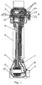
- fig. 1 shows a combined instrument transformer in longitudinal section
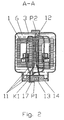
- fig. 2 - a fragment of the instrument transformer from fig. 1 including the instrument transformer head in cross-section along line A-A
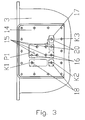
- fig. 3 the front view of the bushing
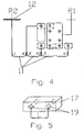
- fig. 4 the wiring diagram of the primary current path of the current instrument transformer
- fig. 5 the cramp in a perspective view.
- the head-type combined instrument transformer comprises a current part in the form of a current instrument transformer 1 and a voltage part in the form of a voltage instrument transformer 2.
- the current instrument transformer 1 is placed in a metal enclosure 3 situated in the upper part of the combined instrument transformer.
- the enclosure 3 is a cast aluminum top tank which is the head of the combined instrument transformer.
- the voltage instrument transformer 2 is situated in the bottom part of the combined instrument transformer, in a cast-aluminum bottom tank 4.
- the metal enclosure 3 is electrically separated from the bottom tank 4 by means of a high-voltage insulator 5 made of porcelain or silicone.
- the inside of the enclosure 3 and of the bottom tank 4 as well as of the insulator 5 is filled with insulating and cooling liquid 6.
- the output leads of the secondary winding 7 of the current instrument transformer 1 and of the secondary winding 8 of the voltage instrument transformer 2 are brought to the terminals of a terminal box 9 connected to the outer part of the bottom tank 4.
- One end of the primary winding of the voltage instrument transformer 2 is directly connected to the wall of the metal enclosure 3, whereas the other end of the primary winding of this instrument transformer is connected through a terminal box 9 to an earth electrode terminal 10 connected to the bottom tank 4.
- the current path 11 of the current instrument transformer 1 is formed by primary windings interconnected in series, and the beginning of the current path 11 is connected with an external current supply terminal P1, and the end is connected with an external current outgoing terminal P2 externally connected to the conducting wall of the enclosure 3 to which, on the inside of the tank, an internal terminal 12 is attached.
- the internal terminal 12 is electrically connected through the enclosure 3 with the external current outgoing terminal P2, to which the external feeder is connected.
- the current supply terminal P1 is a metal plate which is situated in a hollow 13 of a bushing 14 made of resin and tightly fixed in the wall of the upper tank 2.
- the metal plate of the terminal P1 is sealed in the bushing 14 and it has seven threaded holes of which four holes 15 are centrally arranged on the plate of the terminal P1 and they are used to attach the external feeder.
- the other threaded holes 16 are used to connect a single cramp 17, used to change the current range, to one of the external terminals K1, K2 and K3.
- the external terminals K1, K2 and K3 are metal elements with a threaded hole 18.
- the external terminals K1, K2, K3 can be made, for example, as aluminum quadratic prisms or cylinders containing the threaded hole 18. These terminals can be made as threaded segments of metal pipes and they can also have other shapes, which is not shown in the drawing.
- the external terminals K1, K2 and K3 are placed port-like in the bushing 14 in such way that none of these elements touch themselves or the metal plate terminal P1, so that there is no electric contact between these elements.
- the distance between the holes 18 of the terminals K1, K2, K3 and the holes 16 of the terminal plate P1 is identical for each terminal pair K1-P1, K2-P2 and K3-P1.
- the cramp 17 is a metal plate with two holes 19 which are arranged on the face of the plate at a distance "L" corresponding to the distances of the holes of each pair of terminals K1-P1, K2-P2 i K3-P1.
- the instrument transformer according to the invention is suitable for operation within three ranges of rated current whose value is in an interrelation of 1 : 2 : 4. Marking for each terminal K1, K2 and K3 its output as L1, L2 and L3 respectively, the following current paths are obtained:
- Changing the measuring range of the instrument transformer is done in a simple way by unscrewing two fixing bolts 20, switching the cramp 17 to a different position and re-screwing the two fixing bolts, which does not require disconnecting the external feeder.
Landscapes
- Engineering & Computer Science (AREA)
- Power Engineering (AREA)
- Transformers For Measuring Instruments (AREA)
Claims (7)
- Ein Mehrbereichsstrommesswandler für Hochspannungsanwendung, der einen Strompfad (11) enthält, welcher in einem Metallgehäuse (3) untergebracht ist und aus mindestens zwei miteinander elektrisch verbundenen Stromkreisen gebildet wird, die mit einer externen Stromversorgungsklemme (P1) und einer externen Stromausgangsklemme (P2) verbunden sind, wobei die externe Stromversorgungsklemme (P1) eine Metallplatte ist, mit der irgendeine der Klemmen des Strompfades (11) verbunden ist, dadurch gekennzeichnet, dass irgendeine der Klemmen des Strompfades (11) - jeweils nur einem externen Anker (17) einzeln angeschlossen ist und diese in einem Durchführungsisolator (14) angeordnet ist, der fest an der Wand des Metallgehäuses (3) angebracht ist, wobei in dem Durchführungsisolator (14) wenigstens zwei Metallelemente in Form von externen Klemmen (K1, K2 ... Kn) untergebracht sind, die dazu dienen, ein Ende des Strompfades (11) mit der externen Stromversorgungsklemme (P1) mittels nur eines externen Ankers (17) zu verbinden, und das andere Ende des Strompfades (11) dauerhaft mit einer internen Klemme (12) verbunden ist, wobei die interne Klemme (12) eine Kontaktverbindung mit der externen Stromausgangsklemme (P2) und dem einzelnen externen Anker (17) zur Verbindung der Stromversorgungsklemme (P1) mit irgendeiner der Klemmen (K1, K2 ... Kn) auf der äußeren Seite des Durchführungsisolators (14) auf der Außenwand des Metallgehäuses (3) angeordnet ist und die interne Klemme (12) an der Wand des Metallgehäuses innerhalb des Messwandlers befestigt ist und die Stromausgangsklemme (P2) ein integraler Bestandteil des Gehäuses (3) des Messwandlers ist.
- Ein Messwandler gemäß Anspruch 1, dadurch gekennzeichnet, dass die Stromversorgungsklemme (P1) eine rechteckige Metallplatte ist und die externen Klemmen (K1) und (K2) im Durchführungsisolator (14) in der Nähe eines äußeren Randes der Metallplatte der Stromversorgungsklemme (P1) innerhalb des Bereiches des Abstandes der Bolzen, mit denen der Anker (17) befestigt ist, angeordnet sind.
- Ein Messwandler gemäß Anspruch 1, dadurch gekennzeichnet, dass die Stromversorgungsklemme (P1) eine rechteckige Metallplatte ist und die externen Klemmen (K1) und (K2) im Durchführungsisolator (14) in der Nähe eines äußeren Randes der Metallplatte der Stromversorgungsklemme (P1) innerhalb des Bereiches des Abstandes der Bolzen, mit denen der Anker (17) befestigt ist, angeordnet sind und eine Klemme (K3) im Durchführungsisolator (15) in der Nähe eines anderen äußeren Randes der Metallplatte der Stromversorgungsklemme (P1) innerhalb des Bereiches des Abstandes der Bolzen, mit denen der Anker (17) befestigt ist, angeordnet ist.
- Ein Messwandler gemäß Anspruch 1, dadurch gekennzeichnet, dass der Anker (17) die Form eines Quaders hat.
- Ein Messwandler gemäß irgendeinem der vorigen Ansprüche, dadurch gekennzeichnet, dass der Anker (17) mit Bolzen an den externen Klemmen (K1 ... Kn) befestigt ist.
- Ein Messwandler gemäß Anspruch 1 - 4, dadurch gekennzeichnet, dass der Anker (17) mit Schrauben an den externen Klemmen (K1 ... Kn) befestigt ist.
- Ein Messwandler gemäß Anspruch 1, dadurch gekennzeichnet, dass die interne Klemme (12) an der Wand des Gehäuses (3) auf der dem Durchführungsisolator (14) gegenüber liegenden Seite befestigt ist.
Priority Applications (2)
| Application Number | Priority Date | Filing Date | Title |
|---|---|---|---|
| EP10713564A EP2417612B1 (de) | 2009-04-06 | 2010-03-22 | Mehrbereichsstrommesswandler |
| PL10713564T PL2417612T3 (pl) | 2009-04-06 | 2010-03-22 | Wielozakresowy przekładnik prądowy do zastosowań wysokonapięciowych |
Applications Claiming Priority (3)
| Application Number | Priority Date | Filing Date | Title |
|---|---|---|---|
| EP09460015A EP2239744A1 (de) | 2009-04-06 | 2009-04-06 | Mehrbereichsstrommesswandler |
| PCT/EP2010/001894 WO2010115522A1 (en) | 2009-04-06 | 2010-03-22 | Multirange current instrument transformer for high voltage application |
| EP10713564A EP2417612B1 (de) | 2009-04-06 | 2010-03-22 | Mehrbereichsstrommesswandler |
Publications (2)
| Publication Number | Publication Date |
|---|---|
| EP2417612A1 EP2417612A1 (de) | 2012-02-15 |
| EP2417612B1 true EP2417612B1 (de) | 2013-03-06 |
Family
ID=40999903
Family Applications (2)
| Application Number | Title | Priority Date | Filing Date |
|---|---|---|---|
| EP09460015A Withdrawn EP2239744A1 (de) | 2009-04-06 | 2009-04-06 | Mehrbereichsstrommesswandler |
| EP10713564A Not-in-force EP2417612B1 (de) | 2009-04-06 | 2010-03-22 | Mehrbereichsstrommesswandler |
Family Applications Before (1)
| Application Number | Title | Priority Date | Filing Date |
|---|---|---|---|
| EP09460015A Withdrawn EP2239744A1 (de) | 2009-04-06 | 2009-04-06 | Mehrbereichsstrommesswandler |
Country Status (5)
| Country | Link |
|---|---|
| EP (2) | EP2239744A1 (de) |
| CN (1) | CN102379014B (de) |
| ES (1) | ES2406813T3 (de) |
| PL (1) | PL2417612T3 (de) |
| WO (1) | WO2010115522A1 (de) |
Families Citing this family (7)
| Publication number | Priority date | Publication date | Assignee | Title |
|---|---|---|---|---|
| PL66897Y1 (pl) * | 2011-08-31 | 2013-12-31 | Abb Spolka Z Ograniczona Odpowiedzialnoscia | Cewka pradowa wysokiego napiecia |
| EP2565884B1 (de) * | 2011-08-31 | 2014-05-14 | ABB Technology AG | Hochspannungsspule |
| CN104701003A (zh) * | 2015-03-24 | 2015-06-10 | 山东钢铁股份有限公司 | 一种电流互感器的电气接线回路 |
| CN105390261B (zh) * | 2015-10-19 | 2017-05-24 | 长沙润智电子科技有限公司 | 抗干扰电流互感器 |
| EP3208816A1 (de) * | 2016-02-17 | 2017-08-23 | General Electric Technology GmbH | Stromwandler mit sekundären transformationskomponenten in seiner basis |
| CN111933395B (zh) * | 2020-07-30 | 2024-07-09 | 河南许继仪表有限公司 | 一种开启式取电电流互感器及其制作方法 |
| CN116057652A (zh) * | 2020-08-13 | 2023-05-02 | 西门子能源全球有限两合公司 | 电流变换器 |
Family Cites Families (4)
| Publication number | Priority date | Publication date | Assignee | Title |
|---|---|---|---|---|
| GB183480A (en) * | 1921-07-22 | 1923-05-24 | Landis & Gyr Ag | Multiple range electric current transformer |
| CA1051103A (en) * | 1976-05-31 | 1979-03-20 | Westinghouse Canada Limited | Fluid filled transformer |
| JPH08115836A (ja) * | 1994-10-14 | 1996-05-07 | Nissin Electric Co Ltd | 三重比変流器 |
| CN2751421Y (zh) * | 2004-07-14 | 2006-01-11 | 保定天威互感器有限公司 | 一种微油高压电流互感器 |
-
2009
- 2009-04-06 EP EP09460015A patent/EP2239744A1/de not_active Withdrawn
-
2010
- 2010-03-22 WO PCT/EP2010/001894 patent/WO2010115522A1/en not_active Ceased
- 2010-03-22 CN CN201080015235.8A patent/CN102379014B/zh not_active Expired - Fee Related
- 2010-03-22 EP EP10713564A patent/EP2417612B1/de not_active Not-in-force
- 2010-03-22 ES ES10713564T patent/ES2406813T3/es active Active
- 2010-03-22 PL PL10713564T patent/PL2417612T3/pl unknown
Also Published As
| Publication number | Publication date |
|---|---|
| PL2417612T3 (pl) | 2013-05-31 |
| WO2010115522A1 (en) | 2010-10-14 |
| EP2417612A1 (de) | 2012-02-15 |
| CN102379014A (zh) | 2012-03-14 |
| CN102379014B (zh) | 2014-08-20 |
| ES2406813T3 (es) | 2013-06-10 |
| EP2239744A1 (de) | 2010-10-13 |
Similar Documents
| Publication | Publication Date | Title |
|---|---|---|
| EP2417612B1 (de) | Mehrbereichsstrommesswandler | |
| US9714957B2 (en) | High voltage divider | |
| BR102016026326B1 (pt) | Sensor de corrente, aparelho para medir potência ou energia elétrica, comutador de proteção elétrica e dispositivo de comutação | |
| EP2909641A1 (de) | Strom- und/oder spannungserfassungsvorrichtung zur integrativen verwendung | |
| EP3559963B1 (de) | Kombiinstrumenttransformator für hv-anwendungen | |
| US8963670B2 (en) | Tap changer | |
| US20080048814A1 (en) | High voltage transformer | |
| US9058926B2 (en) | Fluid insulated high voltage coil | |
| TWI582436B (zh) | 電量計用端子裝置及電量計 | |
| KR101468254B1 (ko) | 가스절연 개폐장치의 변류기 | |
| US687141A (en) | Current-transformer. | |
| CN107037355A (zh) | 用于高压开关的测量装置 | |
| CN211788475U (zh) | 一种便于自由拆分组合的电流互感器 | |
| EP3964842A1 (de) | Anordnung und schaltvorrichtung mit kontaktloser strommessfähigkeit | |
| CN102435791A (zh) | 计量仪器用变量器装置 | |
| US12405292B2 (en) | Voltage sampler and solid-state transformer | |
| EP3329502B1 (de) | Stromwandler mit leitfähigem stab mit mehrfachdrehung | |
| US1665854A (en) | Alternating-current device | |
| EP3208814B1 (de) | Basiselement zum tragen einer isolierenden säule und eines kopfes eines stromwandlers | |
| EP4538719A1 (de) | Stromdetektor für elektrische installationen | |
| RU202764U1 (ru) | Трансформатор тока с газовой изоляцией | |
| EP3208816A1 (de) | Stromwandler mit sekundären transformationskomponenten in seiner basis | |
| RU2017248C1 (ru) | Трансформатор тока | |
| JP2599806B2 (ja) | 計器用変圧変流器 | |
| RU130131U1 (ru) | Трансформатор тока |
Legal Events
| Date | Code | Title | Description |
|---|---|---|---|
| PUAI | Public reference made under article 153(3) epc to a published international application that has entered the european phase |
Free format text: ORIGINAL CODE: 0009012 |
|
| 17P | Request for examination filed |
Effective date: 20111004 |
|
| AK | Designated contracting states |
Kind code of ref document: A1 Designated state(s): AT BE BG CH CY CZ DE DK EE ES FI FR GB GR HR HU IE IS IT LI LT LU LV MC MK MT NL NO PL PT RO SE SI SK SM TR |
|
| DAX | Request for extension of the european patent (deleted) | ||
| REG | Reference to a national code |
Ref country code: DE Ref legal event code: R079 Ref document number: 602010005301 Country of ref document: DE Free format text: PREVIOUS MAIN CLASS: H01F0027040000 Ipc: H01F0038320000 |
|
| GRAP | Despatch of communication of intention to grant a patent |
Free format text: ORIGINAL CODE: EPIDOSNIGR1 |
|
| RIC1 | Information provided on ipc code assigned before grant |
Ipc: H01F 27/04 20060101ALI20120907BHEP Ipc: H01F 38/28 20060101ALI20120907BHEP Ipc: H01F 38/32 20060101AFI20120907BHEP |
|
| RIN1 | Information on inventor provided before grant (corrected) |
Inventor name: DEBSKI, PAWEL Inventor name: DUZDOWSKI, JAROSLAW Inventor name: LEWANDOWSKI, BOGUSZ Inventor name: WESOLOWSKI, ZBIGNIEW |
|
| GRAP | Despatch of communication of intention to grant a patent |
Free format text: ORIGINAL CODE: EPIDOSNIGR1 |
|
| GRAS | Grant fee paid |
Free format text: ORIGINAL CODE: EPIDOSNIGR3 |
|
| GRAA | (expected) grant |
Free format text: ORIGINAL CODE: 0009210 |
|
| AK | Designated contracting states |
Kind code of ref document: B1 Designated state(s): AT BE BG CH CY CZ DE DK EE ES FI FR GB GR HR HU IE IS IT LI LT LU LV MC MK MT NL NO PL PT RO SE SI SK SM TR |
|
| REG | Reference to a national code |
Ref country code: GB Ref legal event code: FG4D |
|
| REG | Reference to a national code |
Ref country code: CH Ref legal event code: EP Ref country code: AT Ref legal event code: REF Ref document number: 600036 Country of ref document: AT Kind code of ref document: T Effective date: 20130315 |
|
| REG | Reference to a national code |
Ref country code: IE Ref legal event code: FG4D |
|
| REG | Reference to a national code |
Ref country code: DE Ref legal event code: R096 Ref document number: 602010005301 Country of ref document: DE Effective date: 20130502 |
|
| REG | Reference to a national code |
Ref country code: PL Ref legal event code: T3 |
|
| REG | Reference to a national code |
Ref country code: ES Ref legal event code: FG2A Ref document number: 2406813 Country of ref document: ES Kind code of ref document: T3 Effective date: 20130610 |
|
| REG | Reference to a national code |
Ref country code: AT Ref legal event code: MK05 Ref document number: 600036 Country of ref document: AT Kind code of ref document: T Effective date: 20130306 |
|
| PG25 | Lapsed in a contracting state [announced via postgrant information from national office to epo] |
Ref country code: LT Free format text: LAPSE BECAUSE OF FAILURE TO SUBMIT A TRANSLATION OF THE DESCRIPTION OR TO PAY THE FEE WITHIN THE PRESCRIBED TIME-LIMIT Effective date: 20130306 Ref country code: NO Free format text: LAPSE BECAUSE OF FAILURE TO SUBMIT A TRANSLATION OF THE DESCRIPTION OR TO PAY THE FEE WITHIN THE PRESCRIBED TIME-LIMIT Effective date: 20130606 Ref country code: BG Free format text: LAPSE BECAUSE OF FAILURE TO SUBMIT A TRANSLATION OF THE DESCRIPTION OR TO PAY THE FEE WITHIN THE PRESCRIBED TIME-LIMIT Effective date: 20130606 Ref country code: AT Free format text: LAPSE BECAUSE OF FAILURE TO SUBMIT A TRANSLATION OF THE DESCRIPTION OR TO PAY THE FEE WITHIN THE PRESCRIBED TIME-LIMIT Effective date: 20130306 Ref country code: SE Free format text: LAPSE BECAUSE OF FAILURE TO SUBMIT A TRANSLATION OF THE DESCRIPTION OR TO PAY THE FEE WITHIN THE PRESCRIBED TIME-LIMIT Effective date: 20130306 |
|
| REG | Reference to a national code |
Ref country code: NL Ref legal event code: VDEP Effective date: 20130306 |
|
| REG | Reference to a national code |
Ref country code: LT Ref legal event code: MG4D |
|
| PG25 | Lapsed in a contracting state [announced via postgrant information from national office to epo] |
Ref country code: LV Free format text: LAPSE BECAUSE OF FAILURE TO SUBMIT A TRANSLATION OF THE DESCRIPTION OR TO PAY THE FEE WITHIN THE PRESCRIBED TIME-LIMIT Effective date: 20130306 Ref country code: GR Free format text: LAPSE BECAUSE OF FAILURE TO SUBMIT A TRANSLATION OF THE DESCRIPTION OR TO PAY THE FEE WITHIN THE PRESCRIBED TIME-LIMIT Effective date: 20130607 Ref country code: SI Free format text: LAPSE BECAUSE OF FAILURE TO SUBMIT A TRANSLATION OF THE DESCRIPTION OR TO PAY THE FEE WITHIN THE PRESCRIBED TIME-LIMIT Effective date: 20130306 Ref country code: FI Free format text: LAPSE BECAUSE OF FAILURE TO SUBMIT A TRANSLATION OF THE DESCRIPTION OR TO PAY THE FEE WITHIN THE PRESCRIBED TIME-LIMIT Effective date: 20130306 |
|
| PG25 | Lapsed in a contracting state [announced via postgrant information from national office to epo] |
Ref country code: BE Free format text: LAPSE BECAUSE OF FAILURE TO SUBMIT A TRANSLATION OF THE DESCRIPTION OR TO PAY THE FEE WITHIN THE PRESCRIBED TIME-LIMIT Effective date: 20130306 Ref country code: HR Free format text: LAPSE BECAUSE OF FAILURE TO SUBMIT A TRANSLATION OF THE DESCRIPTION OR TO PAY THE FEE WITHIN THE PRESCRIBED TIME-LIMIT Effective date: 20130306 |
|
| PG25 | Lapsed in a contracting state [announced via postgrant information from national office to epo] |
Ref country code: SK Free format text: LAPSE BECAUSE OF FAILURE TO SUBMIT A TRANSLATION OF THE DESCRIPTION OR TO PAY THE FEE WITHIN THE PRESCRIBED TIME-LIMIT Effective date: 20130306 Ref country code: PT Free format text: LAPSE BECAUSE OF FAILURE TO SUBMIT A TRANSLATION OF THE DESCRIPTION OR TO PAY THE FEE WITHIN THE PRESCRIBED TIME-LIMIT Effective date: 20130708 Ref country code: IS Free format text: LAPSE BECAUSE OF FAILURE TO SUBMIT A TRANSLATION OF THE DESCRIPTION OR TO PAY THE FEE WITHIN THE PRESCRIBED TIME-LIMIT Effective date: 20130706 Ref country code: MC Free format text: LAPSE BECAUSE OF NON-PAYMENT OF DUE FEES Effective date: 20130331 Ref country code: NL Free format text: LAPSE BECAUSE OF FAILURE TO SUBMIT A TRANSLATION OF THE DESCRIPTION OR TO PAY THE FEE WITHIN THE PRESCRIBED TIME-LIMIT Effective date: 20130306 Ref country code: CZ Free format text: LAPSE BECAUSE OF FAILURE TO SUBMIT A TRANSLATION OF THE DESCRIPTION OR TO PAY THE FEE WITHIN THE PRESCRIBED TIME-LIMIT Effective date: 20130306 Ref country code: EE Free format text: LAPSE BECAUSE OF FAILURE TO SUBMIT A TRANSLATION OF THE DESCRIPTION OR TO PAY THE FEE WITHIN THE PRESCRIBED TIME-LIMIT Effective date: 20130306 Ref country code: RO Free format text: LAPSE BECAUSE OF FAILURE TO SUBMIT A TRANSLATION OF THE DESCRIPTION OR TO PAY THE FEE WITHIN THE PRESCRIBED TIME-LIMIT Effective date: 20130306 |
|
| REG | Reference to a national code |
Ref country code: IE Ref legal event code: MM4A |
|
| PLBE | No opposition filed within time limit |
Free format text: ORIGINAL CODE: 0009261 |
|
| STAA | Information on the status of an ep patent application or granted ep patent |
Free format text: STATUS: NO OPPOSITION FILED WITHIN TIME LIMIT |
|
| PG25 | Lapsed in a contracting state [announced via postgrant information from national office to epo] |
Ref country code: DK Free format text: LAPSE BECAUSE OF FAILURE TO SUBMIT A TRANSLATION OF THE DESCRIPTION OR TO PAY THE FEE WITHIN THE PRESCRIBED TIME-LIMIT Effective date: 20130306 Ref country code: IE Free format text: LAPSE BECAUSE OF NON-PAYMENT OF DUE FEES Effective date: 20130322 |
|
| 26N | No opposition filed |
Effective date: 20131209 |
|
| PG25 | Lapsed in a contracting state [announced via postgrant information from national office to epo] |
Ref country code: IT Free format text: LAPSE BECAUSE OF FAILURE TO SUBMIT A TRANSLATION OF THE DESCRIPTION OR TO PAY THE FEE WITHIN THE PRESCRIBED TIME-LIMIT Effective date: 20130306 |
|
| REG | Reference to a national code |
Ref country code: DE Ref legal event code: R097 Ref document number: 602010005301 Country of ref document: DE Effective date: 20131209 |
|
| PG25 | Lapsed in a contracting state [announced via postgrant information from national office to epo] |
Ref country code: MT Free format text: LAPSE BECAUSE OF FAILURE TO SUBMIT A TRANSLATION OF THE DESCRIPTION OR TO PAY THE FEE WITHIN THE PRESCRIBED TIME-LIMIT Effective date: 20130306 |
|
| GBPC | Gb: european patent ceased through non-payment of renewal fee |
Effective date: 20140322 |
|
| PG25 | Lapsed in a contracting state [announced via postgrant information from national office to epo] |
Ref country code: GB Free format text: LAPSE BECAUSE OF NON-PAYMENT OF DUE FEES Effective date: 20140322 |
|
| PG25 | Lapsed in a contracting state [announced via postgrant information from national office to epo] |
Ref country code: SM Free format text: LAPSE BECAUSE OF FAILURE TO SUBMIT A TRANSLATION OF THE DESCRIPTION OR TO PAY THE FEE WITHIN THE PRESCRIBED TIME-LIMIT Effective date: 20130306 |
|
| PG25 | Lapsed in a contracting state [announced via postgrant information from national office to epo] |
Ref country code: TR Free format text: LAPSE BECAUSE OF FAILURE TO SUBMIT A TRANSLATION OF THE DESCRIPTION OR TO PAY THE FEE WITHIN THE PRESCRIBED TIME-LIMIT Effective date: 20130306 Ref country code: CY Free format text: LAPSE BECAUSE OF FAILURE TO SUBMIT A TRANSLATION OF THE DESCRIPTION OR TO PAY THE FEE WITHIN THE PRESCRIBED TIME-LIMIT Effective date: 20130306 |
|
| PG25 | Lapsed in a contracting state [announced via postgrant information from national office to epo] |
Ref country code: MK Free format text: LAPSE BECAUSE OF FAILURE TO SUBMIT A TRANSLATION OF THE DESCRIPTION OR TO PAY THE FEE WITHIN THE PRESCRIBED TIME-LIMIT Effective date: 20130306 Ref country code: LU Free format text: LAPSE BECAUSE OF NON-PAYMENT OF DUE FEES Effective date: 20130322 Ref country code: HU Free format text: LAPSE BECAUSE OF FAILURE TO SUBMIT A TRANSLATION OF THE DESCRIPTION OR TO PAY THE FEE WITHIN THE PRESCRIBED TIME-LIMIT; INVALID AB INITIO Effective date: 20100322 |
|
| REG | Reference to a national code |
Ref country code: FR Ref legal event code: PLFP Year of fee payment: 7 |
|
| REG | Reference to a national code |
Ref country code: FR Ref legal event code: PLFP Year of fee payment: 8 |
|
| PGFP | Annual fee paid to national office [announced via postgrant information from national office to epo] |
Ref country code: CH Payment date: 20170322 Year of fee payment: 8 Ref country code: DE Payment date: 20170322 Year of fee payment: 8 Ref country code: FR Payment date: 20170322 Year of fee payment: 8 |
|
| PGFP | Annual fee paid to national office [announced via postgrant information from national office to epo] |
Ref country code: PL Payment date: 20170207 Year of fee payment: 8 |
|
| REG | Reference to a national code |
Ref country code: DE Ref legal event code: R081 Ref document number: 602010005301 Country of ref document: DE Owner name: ABB SCHWEIZ AG, CH Free format text: FORMER OWNER: ABB TECHNOLOGY AG, ZUERICH, CH |
|
| PGFP | Annual fee paid to national office [announced via postgrant information from national office to epo] |
Ref country code: ES Payment date: 20170315 Year of fee payment: 8 |
|
| REG | Reference to a national code |
Ref country code: ES Ref legal event code: PC2A Owner name: ABB SCHWEIZ AG Effective date: 20171213 |
|
| REG | Reference to a national code |
Ref country code: CH Ref legal event code: PFUS Owner name: ABB SCHWEIZ AG, CH Free format text: FORMER OWNER: ABB TECHNOLOGY AG, CH |
|
| REG | Reference to a national code |
Ref country code: DE Ref legal event code: R119 Ref document number: 602010005301 Country of ref document: DE |
|
| REG | Reference to a national code |
Ref country code: FR Ref legal event code: TP Owner name: ABB SCHWEIZ AG, CH Effective date: 20180912 |
|
| REG | Reference to a national code |
Ref country code: CH Ref legal event code: PL |
|
| PG25 | Lapsed in a contracting state [announced via postgrant information from national office to epo] |
Ref country code: DE Free format text: LAPSE BECAUSE OF NON-PAYMENT OF DUE FEES Effective date: 20181002 |
|
| PG25 | Lapsed in a contracting state [announced via postgrant information from national office to epo] |
Ref country code: CH Free format text: LAPSE BECAUSE OF NON-PAYMENT OF DUE FEES Effective date: 20180331 Ref country code: LI Free format text: LAPSE BECAUSE OF NON-PAYMENT OF DUE FEES Effective date: 20180331 |
|
| PG25 | Lapsed in a contracting state [announced via postgrant information from national office to epo] |
Ref country code: FR Free format text: LAPSE BECAUSE OF NON-PAYMENT OF DUE FEES Effective date: 20180331 |
|
| REG | Reference to a national code |
Ref country code: ES Ref legal event code: FD2A Effective date: 20190911 |
|
| PG25 | Lapsed in a contracting state [announced via postgrant information from national office to epo] |
Ref country code: ES Free format text: LAPSE BECAUSE OF NON-PAYMENT OF DUE FEES Effective date: 20180323 |
|
| PG25 | Lapsed in a contracting state [announced via postgrant information from national office to epo] |
Ref country code: PL Free format text: LAPSE BECAUSE OF NON-PAYMENT OF DUE FEES Effective date: 20180322 |