EP3559963B1 - Kombiinstrumenttransformator für hv-anwendungen - Google Patents
Kombiinstrumenttransformator für hv-anwendungen Download PDFInfo
- Publication number
- EP3559963B1 EP3559963B1 EP16826323.4A EP16826323A EP3559963B1 EP 3559963 B1 EP3559963 B1 EP 3559963B1 EP 16826323 A EP16826323 A EP 16826323A EP 3559963 B1 EP3559963 B1 EP 3559963B1
- Authority
- EP
- European Patent Office
- Prior art keywords
- transformer
- instrument transformer
- combined instrument
- voltage
- insulator
- Prior art date
- Legal status (The legal status is an assumption and is not a legal conclusion. Google has not performed a legal analysis and makes no representation as to the accuracy of the status listed.)
- Active
Links
Images


Classifications
-
- H—ELECTRICITY
- H01—ELECTRIC ELEMENTS
- H01F—MAGNETS; INDUCTANCES; TRANSFORMERS; SELECTION OF MATERIALS FOR THEIR MAGNETIC PROPERTIES
- H01F38/00—Adaptations of transformers or inductances for specific applications or functions
- H01F38/20—Instruments transformers
- H01F38/22—Instruments transformers for single phase AC
- H01F38/34—Combined voltage and current transformers
- H01F38/36—Constructions
-
- H—ELECTRICITY
- H01—ELECTRIC ELEMENTS
- H01F—MAGNETS; INDUCTANCES; TRANSFORMERS; SELECTION OF MATERIALS FOR THEIR MAGNETIC PROPERTIES
- H01F27/00—Details of transformers or inductances, in general
- H01F27/02—Casings
-
- H—ELECTRICITY
- H01—ELECTRIC ELEMENTS
- H01F—MAGNETS; INDUCTANCES; TRANSFORMERS; SELECTION OF MATERIALS FOR THEIR MAGNETIC PROPERTIES
- H01F27/00—Details of transformers or inductances, in general
- H01F27/06—Mounting, supporting or suspending transformers, reactors or choke coils not being of the signal type
-
- H—ELECTRICITY
- H01—ELECTRIC ELEMENTS
- H01F—MAGNETS; INDUCTANCES; TRANSFORMERS; SELECTION OF MATERIALS FOR THEIR MAGNETIC PROPERTIES
- H01F27/00—Details of transformers or inductances, in general
- H01F27/24—Magnetic cores
- H01F27/26—Fastening parts of the core together; Fastening or mounting the core on casing or support
Definitions
- the present invention relates to a combined instrument transformer for high voltage (HV) applications.
- the present invention relates to combined instrument transformer for high voltage applications having a greatly simplified structure with respect to the existing instrument transformer.
- the term "combined instrument transformer” designates a measurement instrument for high voltage (HV) applications combining a Current Transformer module and a Voltage (or Potential) Transformer module in one and the same instrument unit.
- HV high voltage
- the term high voltage (HV) is referred to applications above 1kV.
- Instrument transformers - which include Voltage (Potential) Transformers VT (normally of inductive or capacitive type), Current Transformers CT and Combined Instrument Transformers CIT - are well-known types of equipment in high voltage applications, and are typically used for, e.g., metering, monitoring, protection and control of the high voltage system.
- Voltage (Potential) Transformers VT normally of inductive or capacitive type
- Current Transformers CT and Combined Instrument Transformers CIT - are well-known types of equipment in high voltage applications, and are typically used for, e.g., metering, monitoring, protection and control of the high voltage system.
- the combined instrument transformers are measurement instruments which combine in one and the same instrument unit a voltage transformer and a current transformer.
- the current transformer and the voltage transformer are accommodated in a single unit - it is possible to optimize the use of the space in the substation and achieve some cost savings with respect to solutions with two separated measurement units.
- the combined instrument transformers are normally used in the electrical power industry when the space in the substation is limited
- the combined instrument transformers of the known type comprise a dedicated enclosure for each instrument, with one insulating support being sometimes used in between them.
- the typical design of the combined instrument transformer comprises a basement housing one of the instrument transformer, an insulating support vertically protruding from the basement and supporting a dedicated enclosure for the other instrument transformer.
- dielectric systems such as oil or SF6 or other gases with dielectric properties, are normally used.
- the combined instrument transformer design - with the current transformer and the voltage transformer modules in the same measurement unit - gives additional considerable cost savings, since the number of supporting structures and connections is lower, and since the transportation and installation costs are also lower.
- the resulting structure can be bulky since incorporates two enclosures (each housing the CT or the VT) with possibly an intermediate insulator in between said enclosures.
- each enclosure must be provided with one or more sealing to separate one enclosure form the other and/or from the intermediate insulator, with consequent increase of equipment costs as well as increase of manufacturing time and costs.
- the present disclosure is aimed at providing a combined instrument transformer for HV applications which allows overcoming at least some of the above mentioned shortcomings.
- the present disclosure is aimed at providing a combined instrument transformer for HV applications in which the overall dimensions are reduced with respect to the existing solutions.
- the present disclosure is aimed at providing a combined instrument transformer for HV applications in which the sealing, and in general the number of components, can be reduced thereby reducing the equipment costs and simplifying the assembly process.
- the present invention relates to a combined instrument transformer for HV applications, which comprises a current instrument transformer CT, having a current transformer core and a current transformer primary duct fitted into said current transformer core, and a voltage instrument transformer VT, having a voltage transformer core and voltage transformer windings fitted around at least a portion of said voltage transformer core, said current instrument transformer and said voltage instrument transformer being housed in a common internal volume of an enclosure with lateral walls and a top cover.
- Such combined instrument transformers are known from DE3908107 and EP0236974 .
- the internal volume is further delimited by a single base disk insulator, reducing the number of components required for the sealing and, thereby, the equipment costs are reduced and the assembly is simplified. Additional advantageous embodiments are defined by the dependent claims.
- said enclosure housing the current transformer and the voltage transformer typically can comprise first and second primary terminals for connection to a HV line and electrically connected to said current transformer primary duct.
- the enclosure housing the current transformer and the voltage transformer is vertically mounted on a hollow core insulator - or a ceramic insulator in case of oil insulation - and a basement.
- said support device which is a base disk insulator, can separate said internal volume from said hollow core insulator or said ceramic insulator.
- said voltage instrument transformer VT comprise VT secondary wires connected to said voltage transformer windings and said current instrument transformer CT comprises CT secondary wires connected to said current transformer core.
- said current transformer core is shielded into a metallic plate shell.
- said VT secondary wires can be conveniently fitted into another metallic plate shell.
- said current transformer core is preferably supported from below by said base disk insulator.
- said voltage transformer core is preferably supported from the above by said top cover.
- said voltage transformer windings can be preferably supported from the above by said top cover.
- said hollow core insulator or said ceramic insulator comprises a secondary duct running inside said hollow core insulator or said ceramic insulator from said base disk insulator to said basement, said VT secondary wires and said CT secondary wires running inside said secondary duct.
- a combined instrument transformer for HV applications according to the present invention - designated with the reference numeral 1 - in its more general definition comprises a current instrument transformer CT 2 and a voltage instrument transformer VT 3.
- the current instrument transformer CT 2 comprises a current transformer core 21 and a current transformer primary duct 22 which is fitted into said current transformer core 21.
- the a voltage instrument transformer VT 3 comprises a voltage transformer core 31 and voltage transformer windings 32 which are fitted around at least a portion of said voltage transformer core 31
- One of the characterizing features of the combined instrument transformer 1 for HV applications of the present invention is given by the fact that said current instrument transformer CT 2 and said voltage instrument transformer VT 3 are conveniently housed in a common internal volume 41 of a single enclosure 4.
- said common internal volume 41 is delimited by a lateral wall 42, a base disk insulator 43 and a substantially planar cover 44.
- the overall space of the single enclosure 4 is much less than the space and volume normally occupied by the two enclosures normally needed in the combined instrument transformer for separately housing the current instrument transformer CT and the voltage instrument transformer VT.
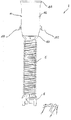
- the combined instrument transformer 1 for HV applications of the present invention is vertically mounted on a hollow core insulator 5 and a basement 6 as shown in the attached figures.
- figure 1 shows an overview of an embodiment of the combined instrument transformer 1 according to the present invention.
- the combined instrument transformer 1 is based on top core design, meaning that the magnetic cores of the current instrument transformer CT 2 and voltage instrument transformer VT 3 are located at the top, where they are fit into the single enclosure 4, and are connected to the HV line through the first 411 and second 412 primary terminals.
- the top portion is supported by a hollow core insulator 5.
- the basement 6 at the bottom of the equipment provides fixation points for a support structure, as well as connection of instrumentation and outlet and terminals for secondary cables.
- the voltage instrument transformer VT 3 conveniently comprise VT secondary wires 35 which are connected to said voltage transformer windings 32.
- the current instrument transformer CT 2 conveniently comprises CT secondary wires 25 which are connected to said current transformer core 21.
- said current transformer core 21 is shielded into a metallic plate shell 28 and is supported from below by said base disk insulator 43.
- said VT secondary wires 35 can be conveniently fitted into said metallic plate shell 28.
- said voltage transformer core 31 is supported form the above by said substantially planar cover 44.
- the voltage transformer windings 32 can be conveniently supported form the above by the substantially planar cover 44.
- the hollow core insulator 5 comprises a secondary duct 55 running inside said hollow core insulator 5 from said base disk insulator 43 to said basement 6, said VT secondary wires 35 and said CT secondary wires 25 running inside said secondary duct 55.
- the voltage transformer core 31 and the voltage transformer windings 32 are positioned into the said single enclosure 4, together with the current instrument transformer CT 2.
- the current transformer primary duct 22 is connected to the enclosure 4 and the first 411 and second 412 primary terminals and is fitted into the current transformer core 21, with one or more turns.
- the VT secondary wires 35 and the CT secondary wires 25 are fitted together into the secondary duct 55, running through the hollow core insulator 5, down to the basement 6.
- the voltage transformer core 31 and the voltage transformer windings 32 are supported from the above by the substantially planar cover 44 which is mounted on the top of the single enclosure 4, while the current transformer core 21 is supported from below by said base disk insulator 43 which separates the internal volume 41 of the enclosure 4 from said hollow core insulator 5.
- the current transformer core 21 is shielded into a metallic plate shell 28.
- the VT secondary wires 35 of the voltage instrument transformer, which are connected to the voltage transformer windings 32, are also fitted into the said Current Transformer metallic plate shell 28, in order to reach the secondary duct 55, passing through the base disk insulator 43 together with the CT secondary wires 25 of the Current Transformer.
- some of the components can have a double function, e.g.: the substantially planar cover 44 closes the internal space 41 of the enclosure 4 from the top and at the same time supports from the above the voltage transformer core 31 and the voltage transformer windings 32; similarly, the base disk insulator 43 separates the internal space 41 of the enclosure 4 from the hollow insulator 5 and at the same time support the current transformer core 21 from below.
- the substantially planar cover 44 closes the internal space 41 of the enclosure 4 from the top and at the same time supports from the above the voltage transformer core 31 and the voltage transformer windings 32; similarly, the base disk insulator 43 separates the internal space 41 of the enclosure 4 from the hollow insulator 5 and at the same time support the current transformer core 21 from below.
Landscapes
- Engineering & Computer Science (AREA)
- Power Engineering (AREA)
- Transformers For Measuring Instruments (AREA)
- Measuring Instrument Details And Bridges, And Automatic Balancing Devices (AREA)
Claims (10)
- Kombinierter Strom- und Spannungswandler (1) für Hochspannungsanwendungen, der einen Stromwandler CT (2), der einen Stromwandlerkern (21) und einen Stromwandler-Primärdurchgang (22), der in den Stromwandlerkern (21) eingesetzt ist, aufweist, und einen Spannungswandler VT (3), der einen Spannungswandlerkern (31) und Spannungswandlerwicklungen (32), die um wenigstens einen Abschnitt des Spannungswandlerkerns (31) eingepasst sind, aufweist, umfasst, wobei der Stromwandler CT (2) und der Spannungswandler VT (3) in einem gemeinsamen Innenvolumen (41) eines einzigen Gehäuses (4) des kombinierten Strom- und Spannungswandlers aufgenommen sind,
wobei das gemeinsame Innenvolumen (41) durch eine seitliche Wand (42), eine Haltevorrichtung (43) und eine obere Abdeckung (44) begrenzt ist, wobei das Gehäuse (4) an einem Hohlkernisolator des kombinierten Strom- und Spannungswandlers oder an einem keramischen Isolator (5) des kombinierten Strom- und Spannungswandlers und an einer Basis (6) des kombinierten Strom- und Spannungswandlers vertikal montiert ist und dadurch gekennzeichnet ist, dass die Haltevorrichtung ein Basisplattenisolator (43) ist. - Kombinierter Strom- und Spannungswandler (1) für Hochspannungsanwendungen nach Anspruch 1, wobei das Gehäuse (4) einen ersten (411) und einen zweiten (412) Primäranschluss zum Verbinden mit einer Hochspannungsleitung umfasst und mit dem Stromwandler-Primärdurchgang (22) elektrisch verbunden ist.
- Kombinierter Strom- und Spannungswandler für Hochspannungsanwendungen nach Anspruch 1 oder 2, wobei der Basisplattenisolator das Innenvolumen vom Hohlkernisolator oder vom keramischen Isolator trennt.
- Kombinierter Strom- und Spannungswandler (1) für Hochspannungsanwendungen nach einem oder mehreren der vorhergehenden Ansprüche, wobei der Spannungswandler VT (3) VT-Sekundärkabel (35) umfasst, die mit den Spannungswandlerwicklungen (32) verbunden sind, und wobei der Stromwandler CT (2) CT-Sekundärkabel (25) umfasst, die mit dem Stromwandlerkern (21) verbunden sind.
- Kombinierter Strom- und Spannungswandler (1) für Hochspannungsanwendungen nach einem oder mehreren der vorhergehenden Ansprüche, wobei der Stromwandlerkern (21) in einer Hülle (28) aus Metallplatten abgeschirmt ist.
- Kombinierter Strom- und Spannungswandler (1) für Hochspannungsanwendungen nach einem oder mehreren der vorhergehenden Ansprüche, wobei der Stromwandlerkern (21) durch den Basisplattenisolator (43) von unten gehalten wird.
- Kombinierter Strom- und Spannungswandler (1) für Hochspannungsanwendungen nach einem oder mehreren der vorhergehenden Ansprüche, wobei der Spannungswandlerkern (31) durch die obere Abdeckung (44) von oben gehalten wird.
- Kombinierter Strom- und Spannungswandler (1) für Hochspannungsanwendungen nach einem oder mehreren der vorhergehenden Ansprüche, wobei die Spannungswandlerwicklungen (32) durch die obere Abdeckung (44) von oben gehalten werden.
- Kombinierter Strom- und Spannungswandler (1) für Hochspannungsanwendungen nach Anspruch 4 oder einem oder mehreren der vorgehenden Ansprüche, wenn sie von Anspruch 4 abhängen, wobei der Hohlkernisolator oder der keramische Isolator (5) einen Sekundärdurchgang (55) aufweist, der vom Basisplattenisolator (43) im Inneren des Hohlkernisolators oder des keramischen Isolators (5) zur Basis (6) verläuft, wobei die VT-Sekundärkabel (35) und die CT-Sekundärkabel (25) im Inneren des Sekundärdurchgangs (55) verlaufen.
- Kombinierter Strom- und Spannungswandler (1) für Hochspannungsanwendungen nach Anspruch 5, wenn er von Anspruch 4 abhängt, oder nach einem oder mehreren der vorhergehenden Ansprüche, wenn sie von Anspruch 5 in Abhängigkeit von Anspruch 4 abhängen, wobei die VT-Sekundärkabel (35) in die Hülle (28) aus Metallplatten eingesetzt sind.
Priority Applications (1)
| Application Number | Priority Date | Filing Date | Title |
|---|---|---|---|
| PL16826323T PL3559963T3 (pl) | 2016-12-21 | 2016-12-21 | Zespolony transformator miernikowy prądowy i napięciowy do zastosowań wysokiego napięcia |
Applications Claiming Priority (1)
| Application Number | Priority Date | Filing Date | Title |
|---|---|---|---|
| PCT/EP2016/082189 WO2018113954A1 (en) | 2016-12-21 | 2016-12-21 | Combined instrument transformer for hv applications. |
Publications (2)
| Publication Number | Publication Date |
|---|---|
| EP3559963A1 EP3559963A1 (de) | 2019-10-30 |
| EP3559963B1 true EP3559963B1 (de) | 2021-09-15 |
Family
ID=57799677
Family Applications (1)
| Application Number | Title | Priority Date | Filing Date |
|---|---|---|---|
| EP16826323.4A Active EP3559963B1 (de) | 2016-12-21 | 2016-12-21 | Kombiinstrumenttransformator für hv-anwendungen |
Country Status (5)
| Country | Link |
|---|---|
| US (1) | US11328863B2 (de) |
| EP (1) | EP3559963B1 (de) |
| CN (1) | CN110088859B (de) |
| PL (1) | PL3559963T3 (de) |
| WO (1) | WO2018113954A1 (de) |
Families Citing this family (6)
| Publication number | Priority date | Publication date | Assignee | Title |
|---|---|---|---|---|
| US10794934B2 (en) | 2017-12-30 | 2020-10-06 | Abb Schweiz Ag | Instrument transformer for measuring at least one electricity property in a conductor of a power grid |
| EP3764378A1 (de) * | 2019-07-12 | 2021-01-13 | Siemens Aktiengesellschaft | Instrumententransformator und verfahren zur isolierung von teilen |
| DE102019214006A1 (de) | 2019-09-13 | 2021-03-18 | Siemens Energy Global GmbH & Co. KG | Deckeleinheit für einen Wandlerkopf einer Hochspannungs-Wandlereinrichtung, Wandlerkopf und Hochspannungs-Wandlereinrichtung |
| DE102019214368B4 (de) * | 2019-09-20 | 2023-02-02 | Siemens Energy Global GmbH & Co. KG | Messwandleranordnung mit einem Spannungswandler und einem Stromwandler |
| EP4060696A1 (de) * | 2021-03-17 | 2022-09-21 | Hitachi Energy Switzerland AG | Hochspannungssäulenstromwandler |
| CN116994867A (zh) * | 2023-08-15 | 2023-11-03 | 特变电工康嘉(沈阳)互感器有限责任公司 | 一种用于超高压电力系统的油浸式绝缘组合互感器 |
Family Cites Families (10)
| Publication number | Priority date | Publication date | Assignee | Title |
|---|---|---|---|---|
| EP0063636B2 (de) * | 1981-04-28 | 1992-12-30 | Sprecher + Schuh AG | Ringkernstromwandler zum Einbau in eine metallgekapselte Hochspannungsschaltanlage |
| BR8700893A (pt) * | 1986-03-13 | 1987-12-22 | Messwandler Bau Ag | Transformador combinado de alta tensao e de corrente de alta tensao |
| DE3737989C1 (de) * | 1987-11-09 | 1989-05-11 | Messwandler Bau Ag | Hochspannungsspannungswandler |
| DE3908107A1 (de) * | 1989-03-13 | 1990-09-20 | Raupach Peter Dipl Volksw | Gasisolierter kombinierter strom- und spannungswandler |
| CN2244246Y (zh) * | 1995-04-14 | 1997-01-01 | 上海Mwb互感器有限公司 | 一种独立式六氟化硫互感器 |
| US8749226B2 (en) * | 2010-05-17 | 2014-06-10 | Abb Technology Ag | Line-powered instrument transformer |
| CN201918255U (zh) * | 2010-11-26 | 2011-08-03 | 江苏思源赫兹互感器有限公司 | 一种组合式电子互感器 |
| CN201936734U (zh) * | 2010-11-30 | 2011-08-17 | 平高集团有限公司 | 一种电子式电流互感器 |
| CN202384165U (zh) * | 2011-10-31 | 2012-08-15 | 许继集团有限公司 | 立式同轴电容结构支柱电子式电流电压组合互感器 |
| CN103208359B (zh) * | 2013-03-21 | 2016-04-20 | 许继集团有限公司 | 一种支柱式气体绝缘电子式电流电压组合互感器 |
-
2016
- 2016-12-21 WO PCT/EP2016/082189 patent/WO2018113954A1/en not_active Ceased
- 2016-12-21 US US16/472,446 patent/US11328863B2/en active Active
- 2016-12-21 EP EP16826323.4A patent/EP3559963B1/de active Active
- 2016-12-21 CN CN201680091738.0A patent/CN110088859B/zh active Active
- 2016-12-21 PL PL16826323T patent/PL3559963T3/pl unknown
Also Published As
| Publication number | Publication date |
|---|---|
| PL3559963T3 (pl) | 2022-02-07 |
| CN110088859A (zh) | 2019-08-02 |
| WO2018113954A1 (en) | 2018-06-28 |
| CN110088859B (zh) | 2021-11-16 |
| US20200388437A1 (en) | 2020-12-10 |
| US11328863B2 (en) | 2022-05-10 |
| EP3559963A1 (de) | 2019-10-30 |
Similar Documents
| Publication | Publication Date | Title |
|---|---|---|
| EP3559963B1 (de) | Kombiinstrumenttransformator für hv-anwendungen | |
| US4808910A (en) | High voltage measurement transformer for suspension from a high voltage switching apparatus | |
| CN104813175B (zh) | 用于综合用途的电流和/或电压感测装置 | |
| NO338301B1 (no) | Transformator med elektrisk avskjerming | |
| US10165695B2 (en) | Apparatus for installing high and low voltage conversion circuit, high and low voltage conversion system and power source | |
| US6680665B2 (en) | Three-phase current transformer | |
| US20150301087A1 (en) | Differential current measuring module | |
| US3942099A (en) | Measuring transformer with a capacitor bushing | |
| US10727757B2 (en) | High voltage high frequency power converter | |
| JP6945657B2 (ja) | 新型の屋内高圧スマート真空ブレーカー | |
| CN202206288U (zh) | 用于总线兼容的安装设备的换流器模块及总线兼容的安装设备 | |
| CN105518813B (zh) | 至少四个电导体的连接 | |
| KR101161863B1 (ko) | 3상 변류기 및 이러한 3상 변류기가 구비된 발전소 | |
| RU162265U1 (ru) | Комплект для оконечных кабельных устройств, для цели присоединения распределительного устройства к высоковольтному кабелю | |
| CN106328363A (zh) | 外置式电流互感器组件及具有其的气体绝缘开关设备 | |
| EP2850624B1 (de) | Transformator mit buchsenfach | |
| KR102841907B1 (ko) | 가스절연개폐기용 전압감지 장치 | |
| JP3203676U (ja) | ガス絶縁スイッチギヤ | |
| US12405292B2 (en) | Voltage sampler and solid-state transformer | |
| EP2117014B1 (de) | Hochspannungsbuchsenkontakt, Hochspannungsbuchse mit einem derartigen Kontakt und Hochspannungsvorrichtung mit einer Buchse mit einem derartigen Kontakt | |
| CN102435791A (zh) | 计量仪器用变量器装置 | |
| RU2540687C1 (ru) | Силовой трансформатор | |
| UA144522U (uk) | Пристрій зв'язку вимірювальних блоків системи телеметрії | |
| JPH08203759A (ja) | ガス絶縁計器用変圧器 | |
| JPH0646608B2 (ja) | 油入電気機器設備 |
Legal Events
| Date | Code | Title | Description |
|---|---|---|---|
| STAA | Information on the status of an ep patent application or granted ep patent |
Free format text: STATUS: UNKNOWN |
|
| STAA | Information on the status of an ep patent application or granted ep patent |
Free format text: STATUS: THE INTERNATIONAL PUBLICATION HAS BEEN MADE |
|
| PUAI | Public reference made under article 153(3) epc to a published international application that has entered the european phase |
Free format text: ORIGINAL CODE: 0009012 |
|
| STAA | Information on the status of an ep patent application or granted ep patent |
Free format text: STATUS: REQUEST FOR EXAMINATION WAS MADE |
|
| 17P | Request for examination filed |
Effective date: 20190702 |
|
| AK | Designated contracting states |
Kind code of ref document: A1 Designated state(s): AL AT BE BG CH CY CZ DE DK EE ES FI FR GB GR HR HU IE IS IT LI LT LU LV MC MK MT NL NO PL PT RO RS SE SI SK SM TR |
|
| AX | Request for extension of the european patent |
Extension state: BA ME |
|
| DAV | Request for validation of the european patent (deleted) | ||
| DAX | Request for extension of the european patent (deleted) | ||
| RAP1 | Party data changed (applicant data changed or rights of an application transferred) |
Owner name: ABB POWER GRIDS SWITZERLAND AG |
|
| GRAP | Despatch of communication of intention to grant a patent |
Free format text: ORIGINAL CODE: EPIDOSNIGR1 |
|
| STAA | Information on the status of an ep patent application or granted ep patent |
Free format text: STATUS: GRANT OF PATENT IS INTENDED |
|
| INTG | Intention to grant announced |
Effective date: 20210316 |
|
| GRAS | Grant fee paid |
Free format text: ORIGINAL CODE: EPIDOSNIGR3 |
|
| GRAA | (expected) grant |
Free format text: ORIGINAL CODE: 0009210 |
|
| STAA | Information on the status of an ep patent application or granted ep patent |
Free format text: STATUS: THE PATENT HAS BEEN GRANTED |
|
| AK | Designated contracting states |
Kind code of ref document: B1 Designated state(s): AL AT BE BG CH CY CZ DE DK EE ES FI FR GB GR HR HU IE IS IT LI LT LU LV MC MK MT NL NO PL PT RO RS SE SI SK SM TR |
|
| REG | Reference to a national code |
Ref country code: CH Ref legal event code: EP |
|
| REG | Reference to a national code |
Ref country code: DE Ref legal event code: R096 Ref document number: 602016063811 Country of ref document: DE |
|
| REG | Reference to a national code |
Ref country code: IE Ref legal event code: FG4D |
|
| REG | Reference to a national code |
Ref country code: AT Ref legal event code: REF Ref document number: 1431164 Country of ref document: AT Kind code of ref document: T Effective date: 20211015 |
|
| REG | Reference to a national code |
Ref country code: CH Ref legal event code: PK Free format text: BERICHTIGUNGEN |
|
| RIN2 | Information on inventor provided after grant (corrected) |
Inventor name: ERRICO, ENNIO Inventor name: MOTTA, ALESSANDRO Inventor name: CALAMARI, MATTEO |
|
| RAP4 | Party data changed (patent owner data changed or rights of a patent transferred) |
Owner name: HITACHI ENERGY SWITZERLAND AG |
|
| REG | Reference to a national code |
Ref country code: LT Ref legal event code: MG9D |
|
| REG | Reference to a national code |
Ref country code: NL Ref legal event code: MP Effective date: 20210915 |
|
| PG25 | Lapsed in a contracting state [announced via postgrant information from national office to epo] |
Ref country code: LT Free format text: LAPSE BECAUSE OF FAILURE TO SUBMIT A TRANSLATION OF THE DESCRIPTION OR TO PAY THE FEE WITHIN THE PRESCRIBED TIME-LIMIT Effective date: 20210915 Ref country code: BG Free format text: LAPSE BECAUSE OF FAILURE TO SUBMIT A TRANSLATION OF THE DESCRIPTION OR TO PAY THE FEE WITHIN THE PRESCRIBED TIME-LIMIT Effective date: 20211215 Ref country code: NO Free format text: LAPSE BECAUSE OF FAILURE TO SUBMIT A TRANSLATION OF THE DESCRIPTION OR TO PAY THE FEE WITHIN THE PRESCRIBED TIME-LIMIT Effective date: 20211215 Ref country code: HR Free format text: LAPSE BECAUSE OF FAILURE TO SUBMIT A TRANSLATION OF THE DESCRIPTION OR TO PAY THE FEE WITHIN THE PRESCRIBED TIME-LIMIT Effective date: 20210915 Ref country code: FI Free format text: LAPSE BECAUSE OF FAILURE TO SUBMIT A TRANSLATION OF THE DESCRIPTION OR TO PAY THE FEE WITHIN THE PRESCRIBED TIME-LIMIT Effective date: 20210915 Ref country code: RS Free format text: LAPSE BECAUSE OF FAILURE TO SUBMIT A TRANSLATION OF THE DESCRIPTION OR TO PAY THE FEE WITHIN THE PRESCRIBED TIME-LIMIT Effective date: 20210915 Ref country code: SE Free format text: LAPSE BECAUSE OF FAILURE TO SUBMIT A TRANSLATION OF THE DESCRIPTION OR TO PAY THE FEE WITHIN THE PRESCRIBED TIME-LIMIT Effective date: 20210915 |
|
| REG | Reference to a national code |
Ref country code: AT Ref legal event code: MK05 Ref document number: 1431164 Country of ref document: AT Kind code of ref document: T Effective date: 20210915 |
|
| PG25 | Lapsed in a contracting state [announced via postgrant information from national office to epo] |
Ref country code: LV Free format text: LAPSE BECAUSE OF FAILURE TO SUBMIT A TRANSLATION OF THE DESCRIPTION OR TO PAY THE FEE WITHIN THE PRESCRIBED TIME-LIMIT Effective date: 20210915 Ref country code: GR Free format text: LAPSE BECAUSE OF FAILURE TO SUBMIT A TRANSLATION OF THE DESCRIPTION OR TO PAY THE FEE WITHIN THE PRESCRIBED TIME-LIMIT Effective date: 20211216 |
|
| PG25 | Lapsed in a contracting state [announced via postgrant information from national office to epo] |
Ref country code: AT Free format text: LAPSE BECAUSE OF FAILURE TO SUBMIT A TRANSLATION OF THE DESCRIPTION OR TO PAY THE FEE WITHIN THE PRESCRIBED TIME-LIMIT Effective date: 20210915 |
|
| PG25 | Lapsed in a contracting state [announced via postgrant information from national office to epo] |
Ref country code: IS Free format text: LAPSE BECAUSE OF FAILURE TO SUBMIT A TRANSLATION OF THE DESCRIPTION OR TO PAY THE FEE WITHIN THE PRESCRIBED TIME-LIMIT Effective date: 20220115 Ref country code: SM Free format text: LAPSE BECAUSE OF FAILURE TO SUBMIT A TRANSLATION OF THE DESCRIPTION OR TO PAY THE FEE WITHIN THE PRESCRIBED TIME-LIMIT Effective date: 20210915 Ref country code: SK Free format text: LAPSE BECAUSE OF FAILURE TO SUBMIT A TRANSLATION OF THE DESCRIPTION OR TO PAY THE FEE WITHIN THE PRESCRIBED TIME-LIMIT Effective date: 20210915 Ref country code: RO Free format text: LAPSE BECAUSE OF FAILURE TO SUBMIT A TRANSLATION OF THE DESCRIPTION OR TO PAY THE FEE WITHIN THE PRESCRIBED TIME-LIMIT Effective date: 20210915 Ref country code: PT Free format text: LAPSE BECAUSE OF FAILURE TO SUBMIT A TRANSLATION OF THE DESCRIPTION OR TO PAY THE FEE WITHIN THE PRESCRIBED TIME-LIMIT Effective date: 20220117 Ref country code: NL Free format text: LAPSE BECAUSE OF FAILURE TO SUBMIT A TRANSLATION OF THE DESCRIPTION OR TO PAY THE FEE WITHIN THE PRESCRIBED TIME-LIMIT Effective date: 20210915 Ref country code: ES Free format text: LAPSE BECAUSE OF FAILURE TO SUBMIT A TRANSLATION OF THE DESCRIPTION OR TO PAY THE FEE WITHIN THE PRESCRIBED TIME-LIMIT Effective date: 20210915 Ref country code: EE Free format text: LAPSE BECAUSE OF FAILURE TO SUBMIT A TRANSLATION OF THE DESCRIPTION OR TO PAY THE FEE WITHIN THE PRESCRIBED TIME-LIMIT Effective date: 20210915 Ref country code: CZ Free format text: LAPSE BECAUSE OF FAILURE TO SUBMIT A TRANSLATION OF THE DESCRIPTION OR TO PAY THE FEE WITHIN THE PRESCRIBED TIME-LIMIT Effective date: 20210915 Ref country code: AL Free format text: LAPSE BECAUSE OF FAILURE TO SUBMIT A TRANSLATION OF THE DESCRIPTION OR TO PAY THE FEE WITHIN THE PRESCRIBED TIME-LIMIT Effective date: 20210915 |
|
| REG | Reference to a national code |
Ref country code: DE Ref legal event code: R097 Ref document number: 602016063811 Country of ref document: DE |
|
| PLBE | No opposition filed within time limit |
Free format text: ORIGINAL CODE: 0009261 |
|
| STAA | Information on the status of an ep patent application or granted ep patent |
Free format text: STATUS: NO OPPOSITION FILED WITHIN TIME LIMIT |
|
| PG25 | Lapsed in a contracting state [announced via postgrant information from national office to epo] |
Ref country code: MC Free format text: LAPSE BECAUSE OF FAILURE TO SUBMIT A TRANSLATION OF THE DESCRIPTION OR TO PAY THE FEE WITHIN THE PRESCRIBED TIME-LIMIT Effective date: 20210915 Ref country code: DK Free format text: LAPSE BECAUSE OF FAILURE TO SUBMIT A TRANSLATION OF THE DESCRIPTION OR TO PAY THE FEE WITHIN THE PRESCRIBED TIME-LIMIT Effective date: 20210915 |
|
| REG | Reference to a national code |
Ref country code: CH Ref legal event code: PL |
|
| 26N | No opposition filed |
Effective date: 20220616 |
|
| GBPC | Gb: european patent ceased through non-payment of renewal fee |
Effective date: 20211221 |
|
| PG25 | Lapsed in a contracting state [announced via postgrant information from national office to epo] |
Ref country code: SI Free format text: LAPSE BECAUSE OF FAILURE TO SUBMIT A TRANSLATION OF THE DESCRIPTION OR TO PAY THE FEE WITHIN THE PRESCRIBED TIME-LIMIT Effective date: 20210915 |
|
| REG | Reference to a national code |
Ref country code: BE Ref legal event code: MM Effective date: 20211231 |
|
| PG25 | Lapsed in a contracting state [announced via postgrant information from national office to epo] |
Ref country code: LU Free format text: LAPSE BECAUSE OF NON-PAYMENT OF DUE FEES Effective date: 20211221 Ref country code: IE Free format text: LAPSE BECAUSE OF NON-PAYMENT OF DUE FEES Effective date: 20211221 Ref country code: GB Free format text: LAPSE BECAUSE OF NON-PAYMENT OF DUE FEES Effective date: 20211221 |
|
| PG25 | Lapsed in a contracting state [announced via postgrant information from national office to epo] |
Ref country code: FR Free format text: LAPSE BECAUSE OF NON-PAYMENT OF DUE FEES Effective date: 20211231 Ref country code: BE Free format text: LAPSE BECAUSE OF NON-PAYMENT OF DUE FEES Effective date: 20211231 |
|
| PG25 | Lapsed in a contracting state [announced via postgrant information from national office to epo] |
Ref country code: LI Free format text: LAPSE BECAUSE OF NON-PAYMENT OF DUE FEES Effective date: 20211231 Ref country code: CH Free format text: LAPSE BECAUSE OF NON-PAYMENT OF DUE FEES Effective date: 20211231 |
|
| PG25 | Lapsed in a contracting state [announced via postgrant information from national office to epo] |
Ref country code: CY Free format text: LAPSE BECAUSE OF FAILURE TO SUBMIT A TRANSLATION OF THE DESCRIPTION OR TO PAY THE FEE WITHIN THE PRESCRIBED TIME-LIMIT Effective date: 20210915 |
|
| P01 | Opt-out of the competence of the unified patent court (upc) registered |
Effective date: 20230527 |
|
| PG25 | Lapsed in a contracting state [announced via postgrant information from national office to epo] |
Ref country code: HU Free format text: LAPSE BECAUSE OF FAILURE TO SUBMIT A TRANSLATION OF THE DESCRIPTION OR TO PAY THE FEE WITHIN THE PRESCRIBED TIME-LIMIT; INVALID AB INITIO Effective date: 20161221 |
|
| PG25 | Lapsed in a contracting state [announced via postgrant information from national office to epo] |
Ref country code: MK Free format text: LAPSE BECAUSE OF FAILURE TO SUBMIT A TRANSLATION OF THE DESCRIPTION OR TO PAY THE FEE WITHIN THE PRESCRIBED TIME-LIMIT Effective date: 20210915 |
|
| REG | Reference to a national code |
Ref country code: DE Ref legal event code: R081 Ref document number: 602016063811 Country of ref document: DE Owner name: HITACHI ENERGY LTD, CH Free format text: FORMER OWNER: ABB POWER GRIDS SWITZERLAND AG, BADEN, CH |
|
| PG25 | Lapsed in a contracting state [announced via postgrant information from national office to epo] |
Ref country code: MT Free format text: LAPSE BECAUSE OF FAILURE TO SUBMIT A TRANSLATION OF THE DESCRIPTION OR TO PAY THE FEE WITHIN THE PRESCRIBED TIME-LIMIT Effective date: 20210915 |
|
| PG25 | Lapsed in a contracting state [announced via postgrant information from national office to epo] |
Ref country code: TR Free format text: LAPSE BECAUSE OF FAILURE TO SUBMIT A TRANSLATION OF THE DESCRIPTION OR TO PAY THE FEE WITHIN THE PRESCRIBED TIME-LIMIT Effective date: 20210915 |
|
| PGFP | Annual fee paid to national office [announced via postgrant information from national office to epo] |
Ref country code: DE Payment date: 20251211 Year of fee payment: 10 |
|
| PGFP | Annual fee paid to national office [announced via postgrant information from national office to epo] |
Ref country code: IT Payment date: 20251223 Year of fee payment: 10 |
|
| PGFP | Annual fee paid to national office [announced via postgrant information from national office to epo] |
Ref country code: PL Payment date: 20251212 Year of fee payment: 10 |