EP2417384B1 - An article, an intermediate product, and a method of making an article - Google Patents
An article, an intermediate product, and a method of making an article Download PDFInfo
- Publication number
- EP2417384B1 EP2417384B1 EP10714657.3A EP10714657A EP2417384B1 EP 2417384 B1 EP2417384 B1 EP 2417384B1 EP 10714657 A EP10714657 A EP 10714657A EP 2417384 B1 EP2417384 B1 EP 2417384B1
- Authority
- EP
- European Patent Office
- Prior art keywords
- layer
- article
- gaps
- substrate
- pockets
- Prior art date
- Legal status (The legal status is an assumption and is not a legal conclusion. Google has not performed a legal analysis and makes no representation as to the accuracy of the status listed.)
- Active
Links
Images




Classifications
-
- C—CHEMISTRY; METALLURGY
- C23—COATING METALLIC MATERIAL; COATING MATERIAL WITH METALLIC MATERIAL; CHEMICAL SURFACE TREATMENT; DIFFUSION TREATMENT OF METALLIC MATERIAL; COATING BY VACUUM EVAPORATION, BY SPUTTERING, BY ION IMPLANTATION OR BY CHEMICAL VAPOUR DEPOSITION, IN GENERAL; INHIBITING CORROSION OF METALLIC MATERIAL OR INCRUSTATION IN GENERAL
- C23C—COATING METALLIC MATERIAL; COATING MATERIAL WITH METALLIC MATERIAL; SURFACE TREATMENT OF METALLIC MATERIAL BY DIFFUSION INTO THE SURFACE, BY CHEMICAL CONVERSION OR SUBSTITUTION; COATING BY VACUUM EVAPORATION, BY SPUTTERING, BY ION IMPLANTATION OR BY CHEMICAL VAPOUR DEPOSITION, IN GENERAL
- C23C4/00—Coating by spraying the coating material in the molten state, e.g. by flame, plasma or electric discharge
- C23C4/02—Pretreatment of the material to be coated, e.g. for coating on selected surface areas
-
- C—CHEMISTRY; METALLURGY
- C23—COATING METALLIC MATERIAL; COATING MATERIAL WITH METALLIC MATERIAL; CHEMICAL SURFACE TREATMENT; DIFFUSION TREATMENT OF METALLIC MATERIAL; COATING BY VACUUM EVAPORATION, BY SPUTTERING, BY ION IMPLANTATION OR BY CHEMICAL VAPOUR DEPOSITION, IN GENERAL; INHIBITING CORROSION OF METALLIC MATERIAL OR INCRUSTATION IN GENERAL
- C23C—COATING METALLIC MATERIAL; COATING MATERIAL WITH METALLIC MATERIAL; SURFACE TREATMENT OF METALLIC MATERIAL BY DIFFUSION INTO THE SURFACE, BY CHEMICAL CONVERSION OR SUBSTITUTION; COATING BY VACUUM EVAPORATION, BY SPUTTERING, BY ION IMPLANTATION OR BY CHEMICAL VAPOUR DEPOSITION, IN GENERAL
- C23C4/00—Coating by spraying the coating material in the molten state, e.g. by flame, plasma or electric discharge
- C23C4/04—Coating by spraying the coating material in the molten state, e.g. by flame, plasma or electric discharge characterised by the coating material
- C23C4/10—Oxides, borides, carbides, nitrides or silicides; Mixtures thereof
- C23C4/11—Oxides
-
- C—CHEMISTRY; METALLURGY
- C23—COATING METALLIC MATERIAL; COATING MATERIAL WITH METALLIC MATERIAL; CHEMICAL SURFACE TREATMENT; DIFFUSION TREATMENT OF METALLIC MATERIAL; COATING BY VACUUM EVAPORATION, BY SPUTTERING, BY ION IMPLANTATION OR BY CHEMICAL VAPOUR DEPOSITION, IN GENERAL; INHIBITING CORROSION OF METALLIC MATERIAL OR INCRUSTATION IN GENERAL
- C23C—COATING METALLIC MATERIAL; COATING MATERIAL WITH METALLIC MATERIAL; SURFACE TREATMENT OF METALLIC MATERIAL BY DIFFUSION INTO THE SURFACE, BY CHEMICAL CONVERSION OR SUBSTITUTION; COATING BY VACUUM EVAPORATION, BY SPUTTERING, BY ION IMPLANTATION OR BY CHEMICAL VAPOUR DEPOSITION, IN GENERAL
- C23C4/00—Coating by spraying the coating material in the molten state, e.g. by flame, plasma or electric discharge
- C23C4/18—After-treatment
-
- F—MECHANICAL ENGINEERING; LIGHTING; HEATING; WEAPONS; BLASTING
- F16—ENGINEERING ELEMENTS AND UNITS; GENERAL MEASURES FOR PRODUCING AND MAINTAINING EFFECTIVE FUNCTIONING OF MACHINES OR INSTALLATIONS; THERMAL INSULATION IN GENERAL
- F16L—PIPES; JOINTS OR FITTINGS FOR PIPES; SUPPORTS FOR PIPES, CABLES OR PROTECTIVE TUBING; MEANS FOR THERMAL INSULATION IN GENERAL
- F16L59/00—Thermal insulation in general
- F16L59/02—Shape or form of insulating materials, with or without coverings integral with the insulating materials
- F16L59/026—Mattresses, mats, blankets or the like
-
- F—MECHANICAL ENGINEERING; LIGHTING; HEATING; WEAPONS; BLASTING
- F16—ENGINEERING ELEMENTS AND UNITS; GENERAL MEASURES FOR PRODUCING AND MAINTAINING EFFECTIVE FUNCTIONING OF MACHINES OR INSTALLATIONS; THERMAL INSULATION IN GENERAL
- F16L—PIPES; JOINTS OR FITTINGS FOR PIPES; SUPPORTS FOR PIPES, CABLES OR PROTECTIVE TUBING; MEANS FOR THERMAL INSULATION IN GENERAL
- F16L59/00—Thermal insulation in general
- F16L59/02—Shape or form of insulating materials, with or without coverings integral with the insulating materials
- F16L59/027—Bands, cords, strips or the like for helically winding around a cylindrical object
-
- F—MECHANICAL ENGINEERING; LIGHTING; HEATING; WEAPONS; BLASTING
- F16—ENGINEERING ELEMENTS AND UNITS; GENERAL MEASURES FOR PRODUCING AND MAINTAINING EFFECTIVE FUNCTIONING OF MACHINES OR INSTALLATIONS; THERMAL INSULATION IN GENERAL
- F16L—PIPES; JOINTS OR FITTINGS FOR PIPES; SUPPORTS FOR PIPES, CABLES OR PROTECTIVE TUBING; MEANS FOR THERMAL INSULATION IN GENERAL
- F16L59/00—Thermal insulation in general
- F16L59/02—Shape or form of insulating materials, with or without coverings integral with the insulating materials
- F16L59/028—Compositions for or methods of fixing a thermally insulating material
-
- F—MECHANICAL ENGINEERING; LIGHTING; HEATING; WEAPONS; BLASTING
- F16—ENGINEERING ELEMENTS AND UNITS; GENERAL MEASURES FOR PRODUCING AND MAINTAINING EFFECTIVE FUNCTIONING OF MACHINES OR INSTALLATIONS; THERMAL INSULATION IN GENERAL
- F16L—PIPES; JOINTS OR FITTINGS FOR PIPES; SUPPORTS FOR PIPES, CABLES OR PROTECTIVE TUBING; MEANS FOR THERMAL INSULATION IN GENERAL
- F16L59/00—Thermal insulation in general
- F16L59/02—Shape or form of insulating materials, with or without coverings integral with the insulating materials
- F16L59/029—Shape or form of insulating materials, with or without coverings integral with the insulating materials layered
-
- F—MECHANICAL ENGINEERING; LIGHTING; HEATING; WEAPONS; BLASTING
- F16—ENGINEERING ELEMENTS AND UNITS; GENERAL MEASURES FOR PRODUCING AND MAINTAINING EFFECTIVE FUNCTIONING OF MACHINES OR INSTALLATIONS; THERMAL INSULATION IN GENERAL
- F16L—PIPES; JOINTS OR FITTINGS FOR PIPES; SUPPORTS FOR PIPES, CABLES OR PROTECTIVE TUBING; MEANS FOR THERMAL INSULATION IN GENERAL
- F16L59/00—Thermal insulation in general
- F16L59/06—Arrangements using an air layer or vacuum
- F16L59/07—Arrangements using an air layer or vacuum the air layer being enclosed by one or more layers of insulation
-
- F—MECHANICAL ENGINEERING; LIGHTING; HEATING; WEAPONS; BLASTING
- F16—ENGINEERING ELEMENTS AND UNITS; GENERAL MEASURES FOR PRODUCING AND MAINTAINING EFFECTIVE FUNCTIONING OF MACHINES OR INSTALLATIONS; THERMAL INSULATION IN GENERAL
- F16L—PIPES; JOINTS OR FITTINGS FOR PIPES; SUPPORTS FOR PIPES, CABLES OR PROTECTIVE TUBING; MEANS FOR THERMAL INSULATION IN GENERAL
- F16L59/00—Thermal insulation in general
- F16L59/08—Means for preventing radiation, e.g. with metal foil
-
- Y—GENERAL TAGGING OF NEW TECHNOLOGICAL DEVELOPMENTS; GENERAL TAGGING OF CROSS-SECTIONAL TECHNOLOGIES SPANNING OVER SEVERAL SECTIONS OF THE IPC; TECHNICAL SUBJECTS COVERED BY FORMER USPC CROSS-REFERENCE ART COLLECTIONS [XRACs] AND DIGESTS
- Y10—TECHNICAL SUBJECTS COVERED BY FORMER USPC
- Y10T—TECHNICAL SUBJECTS COVERED BY FORMER US CLASSIFICATION
- Y10T428/00—Stock material or miscellaneous articles
- Y10T428/24—Structurally defined web or sheet [e.g., overall dimension, etc.]
- Y10T428/24802—Discontinuous or differential coating, impregnation or bond [e.g., artwork, printing, retouched photograph, etc.]
-
- Y—GENERAL TAGGING OF NEW TECHNOLOGICAL DEVELOPMENTS; GENERAL TAGGING OF CROSS-SECTIONAL TECHNOLOGIES SPANNING OVER SEVERAL SECTIONS OF THE IPC; TECHNICAL SUBJECTS COVERED BY FORMER USPC CROSS-REFERENCE ART COLLECTIONS [XRACs] AND DIGESTS
- Y10—TECHNICAL SUBJECTS COVERED BY FORMER USPC
- Y10T—TECHNICAL SUBJECTS COVERED BY FORMER US CLASSIFICATION
- Y10T428/00—Stock material or miscellaneous articles
- Y10T428/24—Structurally defined web or sheet [e.g., overall dimension, etc.]
- Y10T428/24802—Discontinuous or differential coating, impregnation or bond [e.g., artwork, printing, retouched photograph, etc.]
- Y10T428/24851—Intermediate layer is discontinuous or differential
-
- Y—GENERAL TAGGING OF NEW TECHNOLOGICAL DEVELOPMENTS; GENERAL TAGGING OF CROSS-SECTIONAL TECHNOLOGIES SPANNING OVER SEVERAL SECTIONS OF THE IPC; TECHNICAL SUBJECTS COVERED BY FORMER USPC CROSS-REFERENCE ART COLLECTIONS [XRACs] AND DIGESTS
- Y10—TECHNICAL SUBJECTS COVERED BY FORMER USPC
- Y10T—TECHNICAL SUBJECTS COVERED BY FORMER US CLASSIFICATION
- Y10T428/00—Stock material or miscellaneous articles
- Y10T428/24—Structurally defined web or sheet [e.g., overall dimension, etc.]
- Y10T428/24802—Discontinuous or differential coating, impregnation or bond [e.g., artwork, printing, retouched photograph, etc.]
- Y10T428/24917—Discontinuous or differential coating, impregnation or bond [e.g., artwork, printing, retouched photograph, etc.] including metal layer
Definitions
- the invention relates to an article, an intermediate product, and a method of making an article.
- an article comprising a flexible substrate and a thermally sprayed working layer thereon, the working layer including pockets or gaps in which air can collect, wherein the substrate is a metal foil or a composite material including a matrix made of plastics material.
- the article can be wrapped around or moulded onto components or surfaces.
- the flexible substrate is preferably aluminium foil.
- a plurality of the gaps are preferably aligned to form straight, open grooves. This enables the article to be folded at the grooves.
- the elements may be rectangular and may be square. This allows the article to be more flexible in particular directions, for example, for rolling up.
- the article may comprise at least one further flexible substrate over the layer.
- the article includes a further layer on the further flexible substrate, the layer comprising an array of insulating elements, the insulating elements being separated by gaps.
- the further layer is a thermally sprayed layer.
- the thermally sprayed working layer in the article or final product can have increased thermal barrier properties compared to standard thermally sprayed layers as the air pockets or gaps in the layer increase the thermal insulation effect of the layer. Furthermore, as the thermal barrier effect of the layer is increased, a thinner layer is needed to achieve the same thermal barrier effect, and so weight savings can also be realised.
- an article in the form of an intermediate product comprising a flexible substrate with a thermally sprayed working layer thereon, the layer including pockets of a sacrificial material to be removed to form the final product, wherein the substrate is a metal foil or a composite material including a matrix made of plastics material.
- the pockets or gaps may be at least 0.1 mm in diameter, preferably more than 0.5 mm in diameter.
- the pockets or gaps are preferably no more than 5 mm in diameter.
- the pockets or gaps may be at the boundary with the substrate, or may be at the surface of the working layer and open to atmosphere, or may be within the body of the working layer.
- the article preferably has a proportion of the surface which does not have the thermally sprayed layer directly bonded to it being between 10% and 80%, more preferably between 20% and 40%, and most preferably between 25% and 35%.
- thermal barrier properties increase with increasing area of debond, although not in direct proportion.
- the layer is more weakly adhered to the substrate, and so an intermediate level of debond may be preferred.
- the percentage by volume of pockets or gaps in the layer is between 15% and 45%, more preferably between 20% and 40%, and most preferably between 25% and 35%.
- the substrate of the article may be made of or contain an organic material.
- the organic material may be any suitable organic material and may be plastics material or a composite material including a matrix made of plastics material.
- the substrate may be made of glass reinforced plastic composite material or the like, and in a preferred embodiment the surface is made of carbon fibre composite material. Carbon fibre composite materials are popular in a range of industries primarily because of their high strength and low weight.
- the working layer is made of ceramic or metal or ceramic and metal. Where the working layer is made of metal, the working layer may be designed to achieve desired electrical or electromagnetic properties. Where the working layer is made from ceramic, the thermally sprayed layer may be designed to achieve desired thermal barrier or mechanical damage resistance properties.
- the article may include at least one additional layer on the thermally sprayed layer.
- the or each additional layer may also be a thermally sprayed layer or may be deposited in another suitable way such as by electroless deposition, physical vapour deposition (PVD), chemical vapour deposition (CVD) or as a paint or by printing or moulding thereon.
- the or each additional layer may be made of any suitable material and may be made of ceramic or metal or ceramic and metal.
- the or each additional layer may be a thermally sprayed layer, the layer including pockets or gaps in which air can collect.
- the or each additional layer may be a thermally sprayed layer, the layer including pockets of a sacrificial material to be removed to form the final product.
- the total thickness of the layers may be such as to provide increased local mechanical strength.
- the total thickness may be as high as several hundred micrometres.
- the article may include a bonding layer underneath the thermally sprayed layer.
- the bonding layer may be of a material with a lower melting point than the material of the thermally sprayed layer. In this way, a high melting point material can be provided as a layer on a substrate of or containing an organic material in a manner which would not previously have been possible without deleterious melting or degassing or other heat damage to the organic material.
- the layer of bonding material may be of higher melting point than the organic material.
- the bonding material has a melting temperature of no more than 1200 °C, more preferably under 700 °C.
- the layer of bonding material is preferably a metal material, but in another embodiment it may be a ceramic material such as a zirconate ceramic material.
- the bonding material is a metal material it may include one or more of tin, copper, aluminium, silver, gold, lead and zinc. In preferred embodiments the bonding material is copper or aluminium or a copper aluminium alloy.
- the layer of bonding material may be of any desired thickness and may for example be from 2 to 500 micrometres in thickness.
- the layer of bonding material may cover the whole of the said surface of the article or may cover only a selected part of the surface. This may be to achieve a particular technical result, such as electrical conductivity, electromagnetic shielding or electromagnetic transmission or heat resistance, for example, in selected areas or may alternatively or in addition be for decorative purposes.
- the substrate may take any suitable form.
- the substrate is flexible, and may be made from a metal foil. This enables the flexible substrate to wrap around or be moulded onto components or surfaces.
- the article may include a sheet over the layer in order to close the pockets or gaps, so that they are not open to atmosphere.
- the article may include a further layer thereon, the layer including pockets or gaps in which air can collect.
- the further layer may be a thermally sprayed layer.
- a further sheet may be provided thereon.
- the article may include a strengthening layer thereon. Particularly where the percentage by volume of pockets or gaps in the layer is high, this additional layer may be useful in providing extra strength.
- the strengthening layer may be a layer without pockets or gaps and may be a thermally sprayed layer.
- the article may include a further layer thereon, the layer including pockets or gaps in which air can collect.
- the further layer may be a thermally sprayed layer.
- a further strengthening layer may be provided thereon. This provides a suitable balance between thermal barrier properties and strength.
- the pocket or gap creation means may be removed in any suitable way.
- the pocket or gap creation means is soluble and is preferably removed by dissolving.
- the pocket or gap creation means may be suitable for removing by heating and preferably removed by heating.
- the pocket or gap creation means is preferably introduced before or during the step of thermally spraying the surface.
- the step of introducing the pocket or gap creation means may comprise applying a liquid, such as a solution or suspension, to part of the surface of the substrate and then allowing the solution or suspension to dry, creating areas of solid material on the surface.
- a liquid such as a solution or suspension
- the solution may be a salt solution.
- the gap creation means may be a liquid such as a paint or adhesive or other hardenable liquid material applied to part of the surface of the substrate.
- the liquid may be applied through a mesh, or in any other suitable way to achieve an array of areas of debonding material on the substrate.
- the pocket or gap creation means may be applied by thermal spraying, preferably during spraying of the thermally sprayed layer.
- the pocket or gap creation means may be a powder, the pocket or gap creation means powder being mixed with the powder for the thermally sprayed layer and thermally sprayed at the same time as the thermally sprayed layer, preferably by plasma spraying.
- the pocket or gap creation means may be a mesh or other partial barrier, through which the coating is thermally sprayed.
- the step of removing the pocket or gap creation means may be carried out in any suitable way and may comprise mechanically removing the pocket or gap creation means, or dissolving the pocket or gap creation means, or alternatively heating to burn out the pocket or gap creation means, or chemically reacting the pocket or gap creation means.
- thermal spraying technique such as wire spraying
- the step of thermally spraying the substrate with a layer of material comprises plasma spraying the layer onto the substrate.
- Any suitable gas may be used for the plasma spraying and in a preferred embodiment the gas is nitrogen.
- the layer is made of ceramic or metal or ceramic and metal. Where the layer is made of metal, the layer may be designed to achieve desired electrical or electromagnetic properties. Where the layer is made from ceramic, the layer may be designed to achieve desired mechanical damage resistance properties.
- the total thickness of the deposited layers may be such as to provide increased local mechanical strength.
- the total thickness may be as high as several hundred micrometres.
- the method may include roughening the substrate surface prior to thermal spraying thereon.
- the roughening may be effected by mechanical abrasion, for example by grit blasting.
- a bonding layer may be applied by thermal spraying before the step of applying the working layer.
- the bonding layer may be of a higher melting point than the organic material.
- the bonding layer is preferably a metal material, but in another embodiment it may be a silicate material.
- the bonding layer material is a metal material it may include one or more of tin, copper, aluminium, silver, gold, lead and zinc. In preferred embodiments the bonding layer material is copper or aluminium or a copper aluminium alloy.
- the bonding layer may be applied to any desired thickness and may for example be from 2 to 100 micrometres in thickness.
- the bonding layer material may be any suitable material and may be made of a material with a lower melting point than the thermally sprayed layer material. In this way, a high melting point material can be provided as a layer on a surface made of or containing organic material in a manner which would not previously have been possible without deleterious melting or degassing of the organic material.
- the method may include depositing at least one additional bonding layer.
- the or each additional bonding layer may also be deposited by thermal spraying such as plasma spraying or may be deposited in another suitable way such as by electroless deposition, physical vapour deposition (PVD), chemical vapour depostion (CVD) or as a paint or by printing or by moulding.
- the or each additional bonding layer may be made of any suitable material and may be made of ceramic or metal or ceramic and metal.
- the method may include introducing pocket or gap creation means before or concurrently with the step of depositing the or each additional layer to the or each first layer.
- a mild steel plate 10 of dimensions 150 mm x 150 mm by 1.5 mm thick was carefully cleaned, using acetone, then wiped with tissue to remove any liquid.
- the clean plate 10 was then grit blasted on one side using a siphon type grit blast system at 40psi, with grit between 0.4 mm and 0.6 mm in size.
- the plate 10 was blown with dry air to remove any debris and wiped with an acetone damp tissue.
- the plate 10 was then mounted onto a turntable in a plasma spray booth, containing a robot manipulation system.
- the plate 10 was heated up to 200°C using a torch and a steel mesh with 32% open area was placed in front of the plate.
- a sacrificial, pocket creation material in the form of a saturated sodium chloride solution, was sprayed through the mesh to provide an array of sodium chloride solution patches on the surface of the plate 10.
- the sodium chloride solution was allowed to dry, leaving an array of salt patches 12 on the plate 10.
- the spray system was set to work in nitrogen and aluminium powder feed set to spray at 30gm/min. Nitrogen flow was preset to 50litres/min, and current to 300A.
- the robot was programmed to operate a ladder type spray pattern, at a stand off distance of 100 mm from the plate 10, while the plate 10 was rotated. These parameters were used to apply two layers of aluminium to produce an aluminium bond coat of 50 ⁇ m thickness.
- magnesium zirconate was plasma sprayed onto the aluminium coating on the plate 10 at 40-50 gm/min. Four coats gave a layer 16 with a thickness of ⁇ 95-105 ⁇ m..
- the plate was then immersed in water for a few minutes to dissolve the sodium chloride.
- the plate was then washed and immersed in dilute phosphoric acid to pacify the steel.
- Ceramic layers provide good thermal resistance.
- the salt solution acts as a pocket creation means, and an article is formed which has air pockets 18 in the thermally sprayed aluminium bond coat 14 at the positions of the salt patches before the sample is immersed in water. Air is a very good thermal barrier and so the air pockets 18 in the aluminium bond coat 14 improve the thermal resistance of the layer 14,16 as a whole.
- the plate 10 had an increase in thermal barrier properties from both the front and the back, as measured by thermocouples, of approximately 30% compared to a plate with standard ceramic coating, so that the coating, although only 125 ⁇ m thick, outperformed an equivalent coating 300 ⁇ m thick formed without pockets.
- any suitable material which can be applied and subsequently removed can be used, particularly, but not exclusively, those which can be applied by plasma spraying, for example, paint or water soluble tape.
- the pocket creation means may be removed by burning off.
- a coupon 50 of carbon fibre reinforced plastics material of dimensions 150 mm x 150 mm by 2 mm thick was carefully cleaned, using acetone, then wiped with tissue to remove any liquid.
- the clean coupon 50 was then grit blasted on one side using a siphon type grit blast system at 40psi, with grit of between 0.4 and 0.6 mm size.
- the coupon 50 was blown with dry air to remove any debris and wiped with an acetone damp tissue.
- the coupon 50 was then mounted onto a turntable in a plasma spray booth, containing a robot manipulation system.
- the spray system was set to work in nitrogen and the sodium chloride feed set to spray at 30 gm/min.
- the sodium chloride was sieved, in preparation for plasma spraying, to a particle size of below 120 ⁇ m diameter.
- Nitrogen flow was preset to 50 litres/min, hydrogen to 5 litres/min and current to 400 A.
- the robot was programmed to operate a ladder type spray pattern, at a stand off distance of 100mm from the coupon, while the coupon 50 was rotated.
- the sodium chloride was sprayed through the mesh, to create salt dots 52 on the surface of the coupon 50.
- the bond coat had a thickness of approximately 25 ⁇ m.
- a second coat was then applied in the same way to provide a layer 54 with a total coating thickness of 50 ⁇ m.
- magnesium zirconate was plasma sprayed onto the aluminium coating on the coupon 50 at 44gm/min. Five coats gave a layer 56 with a thickness of 150 ⁇ m. This was rubbed down using fine emery paper to give a smooth, shiny surface.
- the coupon 50 was then immersed in water for about 15mins to dissolve the salt pockets and dried.
- the resulting coating contained air pockets 58 where the salt had been.
- the surface of the coating had quite obvious raised dots, where the air pockets were located.
- Carbon fibre reinforced plastics material is naturally relatively soft and susceptible to abrasion.
- the use of an aluminium bond layer 12 in this example allows a layer 14 of ceramic in the form of magnesium zirconate to be applied.
- Carbon fibre reinforced plastic is often used in applications where minimisation of weight is desirable, and especially in applications which need high strength but low weight.
- the ceramic coating produced has above has improved thermal barrier properties over a standard ceramic coating without air pockets. Therefore, for a desired level of thermal resistance, it is possible for the resulting article to be even lighter in relation to its strength, than articles with a standard coating.
- a coupon 100 of mild steel of dimensions 150 mm x 150 mm by 1.5 mm thick was prepared as in embodiment 1 and then mounted onto a turntable in a plasma spray booth, containing a robot manipulation system.
- a Ni-Al bond coat 102 was plasma sprayed onto the coupon 100, using the same parameters as for the bond coat in embodiment 1.
- the coupon was then immersed in water for a few minutes to dissolve the sodium chloride, thus leaving air pockets 110 in the thermal barrier layer 106.
- the first layer was 33% porous. This provides very good thermal barrier characteristics but relatively low strength.
- the addition of a conventionally thermal sprayed layer without a pocket creation material provides improved strength.
- a steel plate 150 which had not been grit blasted was prepared by applying small dots of tape 152 of dimensions 6 mm x 6 mm. to the surface of the plate 150, so that approximately 46% of the surface area of the plate 150 was covered. The plate 150 was then grit-blasted as in embodiment 1.
- the plate 150 was then mounted onto a turntable in a plasma spray booth, containing a robot manipulation system. Two layers of aluminium, each 25 ⁇ m thick, were applied in the same manner as in embodiment 1.to create a bond coat 154.
- the tape 152 was then removed by hand, and the whole surface of the plate 150 was sprayed with a sodium chloride solution, in the same manner as in embodiment 1 (although a mesh was not used). The surface was then rubbed down with a hard grinding block so that the sodium chloride was removed from the bond-coated areas but remained as pockets 156 in the wells where the tape previously was. Further bond coat 158 was then applied over the whole surface in the same manner as the previous layer 154. A layer of magnesium zirconate 160 was plasma sprayed onto the aluminium coating 158 on the plate 150, in the same manner as in embodiment 1.
- the plate was then immersed in water for a few minutes to dissolve the sodium chloride resulting in air pockets 162 in the layer 154.
- the plate was then washed and immersed in dilute phosphoric acid to pacify the steel.
- the percentage of the surface area masked with tape, and subsequently covered with salt solution was 46% in this embodiment, and therefore the debonded area in the final article was 46%, any desired area could be masked so that it is debonded in the final article. In another embodiment 70% debonded area was achieved.
- This embodiment is similar to the first embodiment and only the differences from that embodiment will be described.
- the plate 10 is mounted onto the turntable in the plasma spray booth again, with the aluminium coated side facing the robot.
- the plate 10 is again heated up to 200 °C using a torch and a steel mesh with 32% open area is placed in front of the plate 10.
- Saturated sodium chloride solution is sprayed through the mesh to provide an array of sodium chloride solution patches 12 on the surface of the aluminium layer 14 on the plate 10.
- the sodium chloride solution is allowed to dry, leaving an array of salt patches 12.
- a further aluminium layer 15 is then sprayed over the first aluminium layer 14.
- a magnesium zirconate layer 16 is then plasma sprayed onto the plate 10 as in the first embodiment.
- the plate 10 is then immersed in a bath through which unheated mains cold water flows for 15 minutes to dissolve and thereby remove the salt 12.
- the resulting article has two layers of pockets 18. Thus more air is trapped than would be possible in a single layer structure without risk of the entire layer debonding. This technique therefore allows greater thermal insulation to be achieved using substantially the same manufacturing method.
- substrates in the form of a flat plate have been described, substrates in other shapes could be used, and in that case, the mesh need not be flat but might be shaped to follow the contour of the substrate.
- the substrate for this embodiment was a strip of aluminium foil 200 60 mm wide and 260 mm long, and with a thickness of 0.1 mm.
- the foil 200 was thoroughly cleaned with acetone before use.
- the coupon foil was then mounted onto a turntable in a plasma spray booth, containing a robot manipulation system.
- the spray system was set to work in nitrogen and with an aluminium-bronze feed. Nitrogen flow was preset to 50 litres/min, hydrogen to 3 litres/min and current to 400 A.
- the robot was programmed to operate a ladder type spray pattern, at a stand off distance of 120mm from the foil, while the foil 200 was rotated.
- a 3 mm x 3 mm mesh 202 was attached to the foil 200.
- the foil was thermally sprayed, through the mesh, with an Al-bronze bond coat 204
- a magnesium zirconate layer 206 was then sprayed onto the bond coat 202, through the mesh 202, using the same spraying parameters as for the bond coat, at a stand off distance of 75 mm.
- the mesh 202 was then removed manually.
- the resulting coating on the foil 200 comprised an array of square elements with dimensions of about 2 mm x 2 mm, each comprising an Al-bronze layer 204 and a magnesium zirconate layer 206
- the ceramic has very fine discontinuities in which convective movement of air is restricted, and in which heat transfer by conduction dominates.
- this technique provides a ceramic layer with improved thermal barrier properties, and also a significant weight reduction.
- the underlying foil can remain relatively flexible if the direction of bending is aligned with the air gaps in the ceramic layer. Therefore, the foil of this embodiment can be used to wrap around or be moulded onto components or surfaces which it is not possible or not practical to thermally spray with ceramic directly. Indeed, the article so produced can be rolled up, so that it can be conveniently transported or stored in roll form. This method can also be seen to be useful for other substrates which require flexibility, for example for tubes.
- Multiple layers of foil may be stacked together to trap air in the overall structure.
- gaps which are open to the air are created in the ceramic layer by spraying through a mesh
- sacrificial inclusions for example, tape or salt solution laid down using tape as in embodiment 4
- the air gaps are through the entire thickness of the bond coat and ceramic layers.
Landscapes
- Engineering & Computer Science (AREA)
- General Engineering & Computer Science (AREA)
- Chemical & Material Sciences (AREA)
- Mechanical Engineering (AREA)
- Physics & Mathematics (AREA)
- Plasma & Fusion (AREA)
- Chemical Kinetics & Catalysis (AREA)
- Materials Engineering (AREA)
- Metallurgy (AREA)
- Organic Chemistry (AREA)
- Coating By Spraying Or Casting (AREA)
- Laminated Bodies (AREA)
Description
- The invention relates to an article, an intermediate product, and a method of making an article.
- It is known to coat metal parts, for example engine parts, by plasma spraying with a layer of ceramic or metal material, or to wrap them with a flexible insulating product, as described in documents
WO2008/038013 A2 andUS 4 136 222 . - According to one aspect of the present invention, there is provided an article comprising a flexible substrate and a thermally sprayed working layer thereon, the working layer including pockets or gaps in which air can collect, wherein the substrate is a metal foil or a composite material including a matrix made of plastics material.
- As the substrate is flexible, the article can be wrapped around or moulded onto components or surfaces.
- The flexible substrate is preferably aluminium foil. A plurality of the gaps are preferably aligned to form straight, open grooves. This enables the article to be folded at the grooves. The elements may be rectangular and may be square. This allows the article to be more flexible in particular directions, for example, for rolling up. The article may comprise at least one further flexible substrate over the layer. Preferably the article includes a further layer on the further flexible substrate, the layer comprising an array of insulating elements, the insulating elements being separated by gaps.
- Preferably the further layer is a thermally sprayed layer.
- The thermally sprayed working layer in the article or final product can have increased thermal barrier properties compared to standard thermally sprayed layers as the air pockets or gaps in the layer increase the thermal insulation effect of the layer. Furthermore, as the thermal barrier effect of the layer is increased, a thinner layer is needed to achieve the same thermal barrier effect, and so weight savings can also be realised.
- According to a further aspect of the present invention, there is provided an article in the form of an intermediate product comprising a flexible substrate with a thermally sprayed working layer thereon, the layer including pockets of a sacrificial material to be removed to form the final product, wherein the substrate is a metal foil or a composite material including a matrix made of plastics material.
- The pockets or gaps may be at least 0.1 mm in diameter, preferably more than 0.5 mm in diameter. The pockets or gaps are preferably no more than 5 mm in diameter.
- The pockets or gaps may be at the boundary with the substrate, or may be at the surface of the working layer and open to atmosphere, or may be within the body of the working layer.
- Where the working layer includes pockets or gaps which are open to the substrate, the article preferably has a proportion of the surface which does not have the thermally sprayed layer directly bonded to it being between 10% and 80%, more preferably between 20% and 40%, and most preferably between 25% and 35%.
- The thermal barrier properties increase with increasing area of debond, although not in direct proportion. In addition, in articles with a higher debond proportion, the layer is more weakly adhered to the substrate, and so an intermediate level of debond may be preferred.
- Preferably the percentage by volume of pockets or gaps in the layer is between 15% and 45%, more preferably between 20% and 40%, and most preferably between 25% and 35%.
- The substrate of the article may be made of or contain an organic material. The organic material may be any suitable organic material and may be plastics material or a composite material including a matrix made of plastics material. The substrate may be made of glass reinforced plastic composite material or the like, and in a preferred embodiment the surface is made of carbon fibre composite material. Carbon fibre composite materials are popular in a range of industries primarily because of their high strength and low weight.
- In preferred embodiments the working layer is made of ceramic or metal or ceramic and metal. Where the working layer is made of metal, the working layer may be designed to achieve desired electrical or electromagnetic properties. Where the working layer is made from ceramic, the thermally sprayed layer may be designed to achieve desired thermal barrier or mechanical damage resistance properties.
- The article may include at least one additional layer on the thermally sprayed layer. The or each additional layer may also be a thermally sprayed layer or may be deposited in another suitable way such as by electroless deposition, physical vapour deposition (PVD), chemical vapour deposition (CVD) or as a paint or by printing or moulding thereon. The or each additional layer may be made of any suitable material and may be made of ceramic or metal or ceramic and metal.
- The or each additional layer may be a thermally sprayed layer, the layer including pockets or gaps in which air can collect. Where the article is in the form of an intermediate product, the or each additional layer may be a thermally sprayed layer, the layer including pockets of a sacrificial material to be removed to form the final product.
- The total thickness of the layers may be such as to provide increased local mechanical strength. The total thickness may be as high as several hundred micrometres.
- The article may include a bonding layer underneath the thermally sprayed layer. The bonding layer may be of a material with a lower melting point than the material of the thermally sprayed layer. In this way, a high melting point material can be provided as a layer on a substrate of or containing an organic material in a manner which would not previously have been possible without deleterious melting or degassing or other heat damage to the organic material.
- The layer of bonding material may be of higher melting point than the organic material. Preferably the bonding material has a melting temperature of no more than 1200 °C, more preferably under 700 °C. The layer of bonding material is preferably a metal material, but in another embodiment it may be a ceramic material such as a zirconate ceramic material. Where the bonding material is a metal material it may include one or more of tin, copper, aluminium, silver, gold, lead and zinc. In preferred embodiments the bonding material is copper or aluminium or a copper aluminium alloy.
- The layer of bonding material may be of any desired thickness and may for example be from 2 to 500 micrometres in thickness.
- The layer of bonding material may cover the whole of the said surface of the article or may cover only a selected part of the surface. This may be to achieve a particular technical result, such as electrical conductivity, electromagnetic shielding or electromagnetic transmission or heat resistance, for example, in selected areas or may alternatively or in addition be for decorative purposes.
- The substrate may take any suitable form. The substrate is flexible, and may be made from a metal foil. This enables the flexible substrate to wrap around or be moulded onto components or surfaces.
- Where the pockets or gaps are at the surface of the layer, the article may include a sheet over the layer in order to close the pockets or gaps, so that they are not open to atmosphere. The article may include a further layer thereon, the layer including pockets or gaps in which air can collect. The further layer may be a thermally sprayed layer. A further sheet may be provided thereon.
- Where the pockets or gaps are within the body of the layer, the article may include a strengthening layer thereon. Particularly where the percentage by volume of pockets or gaps in the layer is high, this additional layer may be useful in providing extra strength. The strengthening layer may be a layer without pockets or gaps and may be a thermally sprayed layer. The article may include a further layer thereon, the layer including pockets or gaps in which air can collect. The further layer may be a thermally sprayed layer. A further strengthening layer may be provided thereon. This provides a suitable balance between thermal barrier properties and strength.
- According to another aspect of the invention there is provided a method of making an article, the method comprising the steps of:
- thermally spraying a flexible substrate with a layer of material;
- before, during, or after the step of thermally spraying, introducing pocket or gap creation means; and then
- removing the pocket or gap creation means to achieve a layer with pockets or gaps,
- The pocket or gap creation means may be removed in any suitable way. In one embodiment the pocket or gap creation means is soluble and is preferably removed by dissolving. Alternatively, the pocket or gap creation means may be suitable for removing by heating and preferably removed by heating. In such cases, the pocket or gap creation means is preferably introduced before or during the step of thermally spraying the surface.
- The step of introducing the pocket or gap creation means may comprise applying a liquid, such as a solution or suspension, to part of the surface of the substrate and then allowing the solution or suspension to dry, creating areas of solid material on the surface. In the case of a solution, the solution may be a salt solution. Alternatively, the gap creation means may be a liquid such as a paint or adhesive or other hardenable liquid material applied to part of the surface of the substrate. The liquid may be applied through a mesh, or in any other suitable way to achieve an array of areas of debonding material on the substrate.
- The pocket or gap creation means may be applied by thermal spraying, preferably during spraying of the thermally sprayed layer. The pocket or gap creation means may be a powder, the pocket or gap creation means powder being mixed with the powder for the thermally sprayed layer and thermally sprayed at the same time as the thermally sprayed layer, preferably by plasma spraying.
- The pocket or gap creation means may be a mesh or other partial barrier, through which the coating is thermally sprayed.
- The step of removing the pocket or gap creation means may be carried out in any suitable way and may comprise mechanically removing the pocket or gap creation means, or dissolving the pocket or gap creation means, or alternatively heating to burn out the pocket or gap creation means, or chemically reacting the pocket or gap creation means.
- Any suitable thermal spraying technique may be used, such as wire spraying, and in a preferred embodiment, the step of thermally spraying the substrate with a layer of material comprises plasma spraying the layer onto the substrate. Any suitable gas may be used for the plasma spraying and in a preferred embodiment the gas is nitrogen.
- In preferred embodiments the layer is made of ceramic or metal or ceramic and metal. Where the layer is made of metal, the layer may be designed to achieve desired electrical or electromagnetic properties. Where the layer is made from ceramic, the layer may be designed to achieve desired mechanical damage resistance properties.
- The total thickness of the deposited layers may be such as to provide increased local mechanical strength. The total thickness may be as high as several hundred micrometres.
- The method may include roughening the substrate surface prior to thermal spraying thereon. The roughening may be effected by mechanical abrasion, for example by grit blasting.
- A bonding layer may be applied by thermal spraying before the step of applying the working layer. Where the substrate is made of or contains an organic material, the bonding layer may be of a higher melting point than the organic material. The bonding layer is preferably a metal material, but in another embodiment it may be a silicate material. Where the bonding layer material is a metal material it may include one or more of tin, copper, aluminium, silver, gold, lead and zinc. In preferred embodiments the bonding layer material is copper or aluminium or a copper aluminium alloy.
- The bonding layer may be applied to any desired thickness and may for example be from 2 to 100 micrometres in thickness.
- The bonding layer material may be any suitable material and may be made of a material with a lower melting point than the thermally sprayed layer material. In this way, a high melting point material can be provided as a layer on a surface made of or containing organic material in a manner which would not previously have been possible without deleterious melting or degassing of the organic material.
- The method may include depositing at least one additional bonding layer. The or each additional bonding layer may also be deposited by thermal spraying such as plasma spraying or may be deposited in another suitable way such as by electroless deposition, physical vapour deposition (PVD), chemical vapour depostion (CVD) or as a paint or by printing or by moulding. The or each additional bonding layer may be made of any suitable material and may be made of ceramic or metal or ceramic and metal.
- The method may include introducing pocket or gap creation means before or concurrently with the step of depositing the or each additional layer to the or each first layer.
- Embodiments of this invention will now be descried by way of example and with reference to the accompanying drawings, in which:
-
Fig. 1 is cross sectional views of the first embodiment of the present invention a) before immersing in water to dissolve the salt; and b) after immersing in water so that the salt has dissolved. -
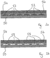
Fig. 2 is cross sectional views of the second embodiment of the present invention a) before immersing in water to dissolve the salt; and b) after immersing in water so that the salt has dissolved. -
Fig. 3 is cross section al views of the third embodiment of the present invention a) before immersing in water to dissolve the salt; and b) after immersing in water so that the salt has dissolved. -
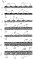
Fig. 4 is cross sectional views of fourth embodiment of the present invention a) with tape on the steel plate; b) with a first bond layer applied; c) with the tape removed; d) with a salt layer applied; e) with the salt layer rubbed down; f) with a second bond layer applied; and g) with a ceramic layer applied. -
Fig. 5 is cross sectional views of the fifth embodiment of the present invention a) before immersing in water to dissolve the salt, and with a first layer of ceramic; b) before immersing in water to dissolve the salt, and with a second layer of ceramic; and c) after immersing in water so that the salt has dissolved. -
Fig. 6 a) is a cross sectional view of the sixth embodiment of the present invention, with a mesh on the foil; b) is a cross sectional view with a bond layer, with the mesh still present; c) is a cross sectional view with a bond layer and a ceramic layer, with the mesh still present; d) is a corss sectional view with a bond layer and a ceramic layer, with the mesh removed; e) is a plan view of the mesh on the substrate; f) is a plan view once the bond layer and ceramic layer have been sprayed, and the mesh has been removed; and g) is a cross section of several layers of foil with air gaps. - A
mild steel plate 10 ofdimensions 150 mm x 150 mm by 1.5 mm thick was carefully cleaned, using acetone, then wiped with tissue to remove any liquid. Theclean plate 10 was then grit blasted on one side using a siphon type grit blast system at 40psi, with grit between 0.4 mm and 0.6 mm in size. Theplate 10 was blown with dry air to remove any debris and wiped with an acetone damp tissue. - The
plate 10 was then mounted onto a turntable in a plasma spray booth, containing a robot manipulation system. Theplate 10 was heated up to 200°C using a torch and a steel mesh with 32% open area was placed in front of the plate. A sacrificial, pocket creation material, in the form of a saturated sodium chloride solution, was sprayed through the mesh to provide an array of sodium chloride solution patches on the surface of theplate 10. The sodium chloride solution was allowed to dry, leaving an array ofsalt patches 12 on theplate 10. - The spray system was set to work in nitrogen and aluminium powder feed set to spray at 30gm/min. Nitrogen flow was preset to 50litres/min, and current to 300A. The robot was programmed to operate a ladder type spray pattern, at a stand off distance of 100 mm from the
plate 10, while theplate 10 was rotated. These parameters were used to apply two layers of aluminium to produce an aluminium bond coat of 50 µm thickness. - Using the same type of spray program at 75mm spray distance, using standard nitrogen plasma parameters, magnesium zirconate was plasma sprayed onto the aluminium coating on the
plate 10 at 40-50 gm/min. Four coats gave alayer 16 with a thickness of ∼95-105 µm.. - The plate was then immersed in water for a few minutes to dissolve the sodium chloride. The plate was then washed and immersed in dilute phosphoric acid to pacify the steel.
- Ceramic layers provide good thermal resistance. Using the above method, the salt solution acts as a pocket creation means, and an article is formed which has
air pockets 18 in the thermally sprayedaluminium bond coat 14 at the positions of the salt patches before the sample is immersed in water. Air is a very good thermal barrier and so theair pockets 18 in thealuminium bond coat 14 improve the thermal resistance of thelayer plate 10 had an increase in thermal barrier properties from both the front and the back, as measured by thermocouples, of approximately 30% compared to a plate with standard ceramic coating, so that the coating, although only 125 µm thick, outperformed an equivalent coating 300 µm thick formed without pockets. - Although in this example salt solution was used, any suitable material which can be applied and subsequently removed can be used, particularly, but not exclusively, those which can be applied by plasma spraying, for example, paint or water soluble tape. In addition, the pocket creation means may be removed by burning off.
- A
coupon 50 of carbon fibre reinforced plastics material ofdimensions 150 mm x 150 mm by 2 mm thick was carefully cleaned, using acetone, then wiped with tissue to remove any liquid. - The
clean coupon 50 was then grit blasted on one side using a siphon type grit blast system at 40psi, with grit of between 0.4 and 0.6 mm size. Thecoupon 50 was blown with dry air to remove any debris and wiped with an acetone damp tissue. - The
coupon 50 was then mounted onto a turntable in a plasma spray booth, containing a robot manipulation system. The spray system was set to work in nitrogen and the sodium chloride feed set to spray at 30 gm/min. The sodium chloride was sieved, in preparation for plasma spraying, to a particle size of below 120 µm diameter. Nitrogen flow was preset to 50 litres/min, hydrogen to 5 litres/min and current to 400 A. The robot was programmed to operate a ladder type spray pattern, at a stand off distance of 100mm from the coupon, while thecoupon 50 was rotated. A fine aluminium mesh, with 1.5 mm diameter holes and 22% open area, was clamped to thecoupon 50. The sodium chloride was sprayed through the mesh, to createsalt dots 52 on the surface of thecoupon 50. - An aluminium bond coat was then thermally sprayed using the same parameters as above. The bond coat had a thickness of approximately 25 µm. A second coat was then applied in the same way to provide a
layer 54 with a total coating thickness of 50 µm. - Using the same type of spray program at 75mm spray distance, using standard nitrogen plasma parameters, magnesium zirconate was plasma sprayed onto the aluminium coating on the
coupon 50 at 44gm/min. Five coats gave alayer 56 with a thickness of 150 µm. This was rubbed down using fine emery paper to give a smooth, shiny surface. - Repeating the aluminium spray program, but only applying one coat on top of the magnesium zirconate coating, gave a thin 25
µm metal layer 16. - The
coupon 50 was then immersed in water for about 15mins to dissolve the salt pockets and dried. The resulting coating containedair pockets 58 where the salt had been. The surface of the coating had quite obvious raised dots, where the air pockets were located. - Carbon fibre reinforced plastics material is naturally relatively soft and susceptible to abrasion. The use of an
aluminium bond layer 12 in this example allows alayer 14 of ceramic in the form of magnesium zirconate to be applied. Carbon fibre reinforced plastic is often used in applications where minimisation of weight is desirable, and especially in applications which need high strength but low weight. The ceramic coating produced has above has improved thermal barrier properties over a standard ceramic coating without air pockets. Therefore, for a desired level of thermal resistance, it is possible for the resulting article to be even lighter in relation to its strength, than articles with a standard coating. - A
coupon 100 of mild steel ofdimensions 150 mm x 150 mm by 1.5 mm thick was prepared as in embodiment 1 and then mounted onto a turntable in a plasma spray booth, containing a robot manipulation system. A Ni-Al bond coat 102 was plasma sprayed onto thecoupon 100, using the same parameters as for the bond coat in embodiment 1. - Sodium chloride powder, sieved so that the maximum particle diameter was <120 µm was mixed with magnesium zirconate powder to a volume of 50%. This was sprayed using the same spray parameters as in embodiment 1 to produce a layer with
salt 104 dispersed inthermal barrier material 106. A furtherceramic coating 108, without salt, was then applied, in the same manner. - The coupon was then immersed in water for a few minutes to dissolve the sodium chloride, thus leaving
air pockets 110 in thethermal barrier layer 106. - The first layer was 33% porous. This provides very good thermal barrier characteristics but relatively low strength. The addition of a conventionally thermal sprayed layer without a pocket creation material provides improved strength.
- A
steel plate 150 which had not been grit blasted was prepared by applying small dots oftape 152 of dimensions 6 mm x 6 mm. to the surface of theplate 150, so that approximately 46% of the surface area of theplate 150 was covered. Theplate 150 was then grit-blasted as in embodiment 1. - The
plate 150 was then mounted onto a turntable in a plasma spray booth, containing a robot manipulation system. Two layers of aluminium, each 25 µm thick, were applied in the same manner as in embodiment 1.to create abond coat 154. - The
tape 152 was then removed by hand, and the whole surface of theplate 150 was sprayed with a sodium chloride solution, in the same manner as in embodiment 1 (although a mesh was not used). The surface was then rubbed down with a hard grinding block so that the sodium chloride was removed from the bond-coated areas but remained aspockets 156 in the wells where the tape previously was.Further bond coat 158 was then applied over the whole surface in the same manner as theprevious layer 154. A layer ofmagnesium zirconate 160 was plasma sprayed onto thealuminium coating 158 on theplate 150, in the same manner as in embodiment 1. - The plate was then immersed in water for a few minutes to dissolve the sodium chloride resulting in
air pockets 162 in thelayer 154. The plate was then washed and immersed in dilute phosphoric acid to pacify the steel. - Although the percentage of the surface area masked with tape, and subsequently covered with salt solution was 46% in this embodiment, and therefore the debonded area in the final article was 46%, any desired area could be masked so that it is debonded in the final article. In another embodiment 70% debonded area was achieved.
- This embodiment is similar to the first embodiment and only the differences from that embodiment will be described. In this embodiment, after the
aluminium layer 14 has been sprayed, theplate 10 is mounted onto the turntable in the plasma spray booth again, with the aluminium coated side facing the robot. Theplate 10 is again heated up to 200 °C using a torch and a steel mesh with 32% open area is placed in front of theplate 10. Saturated sodium chloride solution, is sprayed through the mesh to provide an array of sodiumchloride solution patches 12 on the surface of thealuminium layer 14 on theplate 10. The sodium chloride solution is allowed to dry, leaving an array ofsalt patches 12. Afurther aluminium layer 15 is then sprayed over thefirst aluminium layer 14. Amagnesium zirconate layer 16 is then plasma sprayed onto theplate 10 as in the first embodiment. Theplate 10 is then immersed in a bath through which unheated mains cold water flows for 15 minutes to dissolve and thereby remove thesalt 12. - The resulting article has two layers of
pockets 18. Thus more air is trapped than would be possible in a single layer structure without risk of the entire layer debonding. This technique therefore allows greater thermal insulation to be achieved using substantially the same manufacturing method. - An alternative would be to spray salt patches on the surface of the
second aluminium layer 15, and then spray themagnesium zirconate layer 16, to create an arrangement in which themagnesium zirconate 16 layer also hasair pockets 18. - Although a substrate in the form of a flat plate has been described, substrates in other shapes could be used, and in that case, the mesh need not be flat but might be shaped to follow the contour of the substrate.
- The substrate for this embodiment was a strip of
aluminium foil 200 60 mm wide and 260 mm long, and with a thickness of 0.1 mm. Thefoil 200 was thoroughly cleaned with acetone before use. The coupon foil was then mounted onto a turntable in a plasma spray booth, containing a robot manipulation system. The spray system was set to work in nitrogen and with an aluminium-bronze feed. Nitrogen flow was preset to 50 litres/min, hydrogen to 3 litres/min and current to 400 A. The robot was programmed to operate a ladder type spray pattern, at a stand off distance of 120mm from the foil, while thefoil 200 was rotated. A 3 mm x 3mm mesh 202 was attached to thefoil 200. The foil was thermally sprayed, through the mesh, with an Al-bronze bond coat 204 - A
magnesium zirconate layer 206 was then sprayed onto thebond coat 202, through themesh 202, using the same spraying parameters as for the bond coat, at a stand off distance of 75 mm. Themesh 202 was then removed manually. The resulting coating on thefoil 200 comprised an array of square elements with dimensions of about 2 mm x 2 mm, each comprising an Al-bronze layer 204 and amagnesium zirconate layer 206 - Thus the ceramic has very fine discontinuities in which convective movement of air is restricted, and in which heat transfer by conduction dominates. Thus by utilising the low thermal conductivity of air, this technique provides a ceramic layer with improved thermal barrier properties, and also a significant weight reduction. Further, the underlying foil can remain relatively flexible if the direction of bending is aligned with the air gaps in the ceramic layer. Therefore, the foil of this embodiment can be used to wrap around or be moulded onto components or surfaces which it is not possible or not practical to thermally spray with ceramic directly. Indeed, the article so produced can be rolled up, so that it can be conveniently transported or stored in roll form. This method can also be seen to be useful for other substrates which require flexibility, for example for tubes.
- Multiple layers of foil may be stacked together to trap air in the overall structure.
- Although in this embodiment gaps which are open to the air are created in the ceramic layer by spraying through a mesh, sacrificial inclusions, for example, tape or salt solution laid down using tape as in embodiment 4, could be used to create a mesh-like pattern to produce a similar effect in the final ceramic layer once the sacrificial inclusions are removed, for example by dissolving or burning out.
- In addition, in the above embodiment, the air gaps are through the entire thickness of the bond coat and ceramic layers. However, it should be seen that it would also be possible to create an arrangement in which the air gaps do not extend the entire depth of the bond layer and ceramic layer for example by using a different mesh; by applying the bond coat to the whole of the foil surface, and then masking the bond coat in suitable way, and spraying only the ceramic layer through the mask: or by applying one coat of ceramic, masking the coat in a suitable way, and then applying another coat of ceramic.
Claims (15)
- An article comprising a flexible substrate and a thermally sprayed working layer thereon, the working layer including pockets or gaps in which air can collect, wherein the substrate is a metal foil or a composite material including a matrix made of plastics material.
- An article as claimed in claim 1, wherein the article is an article for insulation, the working layer comprising an array of insulating elements, the insulating elements being separated by gaps so that the article is flexible.
- An article as claimed in claim 2, wherein a plurality of the gaps are aligned to form straight, open grooves and optionally the elements are rectangular and may be square.
- An article according to claim 1, 2 or 3, wherein the article comprises at least one further flexible substrate over the working layer.
- An article as claimed in claim 4, wherein the article includes a further working layer on the further flexible substrate, the further working layer optionally comprising an array of insulating elements, the insulating elements being separated by gaps.
- An article according to claim 5, wherein the further working layer is a thermally sprayed layer.
- An article in the form of an intermediate product comprising a flexible substrate with a thermally sprayed working layer thereon, the working layer including pockets of a sacrificial material to be removed to form the final product, wherein the substrate is a metal foil or a composite material including a matrix made of plastics material.
- An article according to any preceding claim, wherein the working layer is made of ceramic.
- An article according to any preceding claim, wherein the substrate is aluminium foil.
- An article according to any preceding claim, wherein the pockets or gaps are more than 0.5 mm in size and/or wherein the pockets or gaps are no more than 5 mm in size.
- An article according to any preceding claim, wherein the percentage by volume of pockets or gaps in the layer is between 15% and 45 % and may be between 20% and 40% and may be between 25% and 35%.
- A method of making an article, the method comprising the steps of: thermally spraying a flexible substrate with a layer of material; before, during, or after the step of thermally spraying, introducing pocket or gap creation means; and then removing the pocket or gap creation means to achieve a layer with pockets or gaps, wherein the substrate is a metal foil or a composite material including a matrix made of plastics material.
- A method according to claim 12 , wherein the pocket or gap creation means is a liquid such as a paint or adhesive or other hardenable liquid material applied to part of the surface of the substrate and optionally the liquid is applied through a mesh, or in any other suitable way, to achieve an array of areas of debonding material on the substrate.
- A method according to claim 12 or claim 13, wherein the pocket or gap creation means is a mesh or other partial barrier, through which the coating is thermally sprayed and optionally the step of removing the pocket or gap creation means comprises mechanically removing the pocket or gap creation means.
- A method according to any of claims 12, 13 and 14, wherein the thermally sprayed layer of material is an insulating material.
Priority Applications (1)
| Application Number | Priority Date | Filing Date | Title |
|---|---|---|---|
| PL10714657T PL2417384T3 (en) | 2009-04-09 | 2010-04-09 | An article, an intermediate product, and a method of making an article |
Applications Claiming Priority (2)
| Application Number | Priority Date | Filing Date | Title |
|---|---|---|---|
| GBGB0906312.4A GB0906312D0 (en) | 2009-04-09 | 2009-04-09 | An article, an intermediate product and a method of making an article |
| PCT/GB2010/000744 WO2010116159A1 (en) | 2009-04-09 | 2010-04-09 | An article, an intermediate product, and a method of making an article |
Publications (2)
| Publication Number | Publication Date |
|---|---|
| EP2417384A1 EP2417384A1 (en) | 2012-02-15 |
| EP2417384B1 true EP2417384B1 (en) | 2020-07-08 |
Family
ID=40750489
Family Applications (1)
| Application Number | Title | Priority Date | Filing Date |
|---|---|---|---|
| EP10714657.3A Active EP2417384B1 (en) | 2009-04-09 | 2010-04-09 | An article, an intermediate product, and a method of making an article |
Country Status (6)
| Country | Link |
|---|---|
| US (1) | US10047427B2 (en) |
| EP (1) | EP2417384B1 (en) |
| ES (1) | ES2809239T3 (en) |
| GB (1) | GB0906312D0 (en) |
| PL (1) | PL2417384T3 (en) |
| WO (1) | WO2010116159A1 (en) |
Families Citing this family (2)
| Publication number | Priority date | Publication date | Assignee | Title |
|---|---|---|---|---|
| EP2554708A1 (en) * | 2011-08-02 | 2013-02-06 | Neue Materialien Bayreuth GmbH | Method for producing a metallic workpiece with at least one cavity |
| KR102108360B1 (en) * | 2013-06-19 | 2020-05-11 | 삼성디스플레이 주식회사 | Method for processing substrate and flexible display apparatus manufactured by using the method |
Citations (2)
| Publication number | Priority date | Publication date | Assignee | Title |
|---|---|---|---|---|
| US4136222A (en) * | 1977-04-18 | 1979-01-23 | Minnesota Mining And Manufacturing Company | Thermally insulating sheet material |
| WO2008038013A2 (en) * | 2006-09-29 | 2008-04-03 | Specialist Insulation Limited | Insulated ductwork products |
Family Cites Families (1)
| Publication number | Priority date | Publication date | Assignee | Title |
|---|---|---|---|---|
| US7198860B2 (en) * | 2003-04-25 | 2007-04-03 | Siemens Power Generation, Inc. | Ceramic tile insulation for gas turbine component |
-
2009
- 2009-04-09 GB GBGB0906312.4A patent/GB0906312D0/en not_active Ceased
-
2010
- 2010-04-09 US US13/138,844 patent/US10047427B2/en active Active
- 2010-04-09 EP EP10714657.3A patent/EP2417384B1/en active Active
- 2010-04-09 ES ES10714657T patent/ES2809239T3/en active Active
- 2010-04-09 PL PL10714657T patent/PL2417384T3/en unknown
- 2010-04-09 WO PCT/GB2010/000744 patent/WO2010116159A1/en not_active Ceased
Patent Citations (2)
| Publication number | Priority date | Publication date | Assignee | Title |
|---|---|---|---|---|
| US4136222A (en) * | 1977-04-18 | 1979-01-23 | Minnesota Mining And Manufacturing Company | Thermally insulating sheet material |
| WO2008038013A2 (en) * | 2006-09-29 | 2008-04-03 | Specialist Insulation Limited | Insulated ductwork products |
Also Published As
| Publication number | Publication date |
|---|---|
| US20120114915A1 (en) | 2012-05-10 |
| EP2417384A1 (en) | 2012-02-15 |
| WO2010116159A1 (en) | 2010-10-14 |
| PL2417384T3 (en) | 2021-05-04 |
| GB0906312D0 (en) | 2009-05-20 |
| ES2809239T3 (en) | 2021-03-03 |
| US10047427B2 (en) | 2018-08-14 |
Similar Documents
| Publication | Publication Date | Title |
|---|---|---|
| AU2006254135B2 (en) | Porous metal foam body | |
| EP3327167A1 (en) | A wheel comprising an organic material, at least a surface and a thermally sprayed layer thereon, and a method of making the wheel | |
| KR100432075B1 (en) | A method of coating a non-wetting fluid material on a substrate, a method of manufacturing a ceramic metal structure, a method of bonding a plurality of ceramic bodies, and a layered structure formed by such a method | |
| EP1295964A3 (en) | Dual microstructure thermal barrier coating | |
| EP0455419B1 (en) | Coating steel articles | |
| US20080149322A1 (en) | Metal Coated Graphite Sheet | |
| KR101579239B1 (en) | Lamination and method for manufacturing lamination | |
| SE0203223D0 (en) | Method of making structured ceramic coatings and coated devices prepared with the method | |
| EP2371986B1 (en) | Metallic coating for non-line of sight areas | |
| EP0988898A3 (en) | Thermal spray application of polymeric material | |
| WO2011038406A3 (en) | Highly electrically conductive surfaces for electrochemical applications and methods to produce same | |
| JP2008542540A5 (en) | ||
| WO2007005832A3 (en) | Reliant thermal barrier coating system and related methods and apparatus of making the same | |
| US9764351B2 (en) | Method of coating a substrate | |
| CN108368617A (en) | The plating method of steel plate and the metal coated steel plates manufactured using it | |
| JPH1054395A5 (en) | ||
| US10047427B2 (en) | Article, an intermediate product, and a method of making an article | |
| WO2006110409A1 (en) | Metal sprayed composite part | |
| ES2283312T3 (en) | NANO-STRUCTURAL COATINGS. | |
| JP2006516681A (en) | Pre-plating surface treatment to increase electrical corrosion resistance | |
| JP2001164379A (en) | Surface treating method and joining method | |
| US20240084457A1 (en) | Expansive coatings for anchoring to composite substrates | |
| US7700162B2 (en) | Method for coating graphite foil | |
| KR100797827B1 (en) | Coating method on carbon fiber-epoxy composite | |
| KR100856662B1 (en) | Metal film formation method on plastic substrate |
Legal Events
| Date | Code | Title | Description |
|---|---|---|---|
| PUAI | Public reference made under article 153(3) epc to a published international application that has entered the european phase |
Free format text: ORIGINAL CODE: 0009012 |
|
| 17P | Request for examination filed |
Effective date: 20111004 |
|
| AK | Designated contracting states |
Kind code of ref document: A1 Designated state(s): AT BE BG CH CY CZ DE DK EE ES FI FR GB GR HR HU IE IS IT LI LT LU LV MC MK MT NL NO PL PT RO SE SI SK SM TR |
|
| DAX | Request for extension of the european patent (deleted) | ||
| RAP1 | Party data changed (applicant data changed or rights of an application transferred) |
Owner name: ZIRCOTEC IP LIMITED |
|
| STAA | Information on the status of an ep patent application or granted ep patent |
Free format text: STATUS: REQUEST FOR EXAMINATION WAS MADE |
|
| STAA | Information on the status of an ep patent application or granted ep patent |
Free format text: STATUS: EXAMINATION IS IN PROGRESS |
|
| 17Q | First examination report despatched |
Effective date: 20181207 |
|
| GRAP | Despatch of communication of intention to grant a patent |
Free format text: ORIGINAL CODE: EPIDOSNIGR1 |
|
| STAA | Information on the status of an ep patent application or granted ep patent |
Free format text: STATUS: GRANT OF PATENT IS INTENDED |
|
| INTG | Intention to grant announced |
Effective date: 20191127 |
|
| GRAS | Grant fee paid |
Free format text: ORIGINAL CODE: EPIDOSNIGR3 |
|
| GRAA | (expected) grant |
Free format text: ORIGINAL CODE: 0009210 |
|
| STAA | Information on the status of an ep patent application or granted ep patent |
Free format text: STATUS: THE PATENT HAS BEEN GRANTED |
|
| AK | Designated contracting states |
Kind code of ref document: B1 Designated state(s): AT BE BG CH CY CZ DE DK EE ES FI FR GB GR HR HU IE IS IT LI LT LU LV MC MK MT NL NO PL PT RO SE SI SK SM TR |
|
| REG | Reference to a national code |
Ref country code: GB Ref legal event code: FG4D |
|
| REG | Reference to a national code |
Ref country code: CH Ref legal event code: EP Ref country code: AT Ref legal event code: REF Ref document number: 1288837 Country of ref document: AT Kind code of ref document: T Effective date: 20200715 |
|
| REG | Reference to a national code |
Ref country code: DE Ref legal event code: R096 Ref document number: 602010064848 Country of ref document: DE |
|
| REG | Reference to a national code |
Ref country code: IE Ref legal event code: FG4D |
|
| REG | Reference to a national code |
Ref country code: SE Ref legal event code: TRGR |
|
| REG | Reference to a national code |
Ref country code: NL Ref legal event code: FP |
|
| REG | Reference to a national code |
Ref country code: CH Ref legal event code: NV Representative=s name: AMMANN PATENTANWAELTE AG BERN, CH |
|
| REG | Reference to a national code |
Ref country code: LT Ref legal event code: MG4D |
|
| REG | Reference to a national code |
Ref country code: AT Ref legal event code: MK05 Ref document number: 1288837 Country of ref document: AT Kind code of ref document: T Effective date: 20200708 |
|
| PG25 | Lapsed in a contracting state [announced via postgrant information from national office to epo] |
Ref country code: HR Free format text: LAPSE BECAUSE OF FAILURE TO SUBMIT A TRANSLATION OF THE DESCRIPTION OR TO PAY THE FEE WITHIN THE PRESCRIBED TIME-LIMIT Effective date: 20200708 Ref country code: LT Free format text: LAPSE BECAUSE OF FAILURE TO SUBMIT A TRANSLATION OF THE DESCRIPTION OR TO PAY THE FEE WITHIN THE PRESCRIBED TIME-LIMIT Effective date: 20200708 Ref country code: AT Free format text: LAPSE BECAUSE OF FAILURE TO SUBMIT A TRANSLATION OF THE DESCRIPTION OR TO PAY THE FEE WITHIN THE PRESCRIBED TIME-LIMIT Effective date: 20200708 Ref country code: BG Free format text: LAPSE BECAUSE OF FAILURE TO SUBMIT A TRANSLATION OF THE DESCRIPTION OR TO PAY THE FEE WITHIN THE PRESCRIBED TIME-LIMIT Effective date: 20201008 Ref country code: PT Free format text: LAPSE BECAUSE OF FAILURE TO SUBMIT A TRANSLATION OF THE DESCRIPTION OR TO PAY THE FEE WITHIN THE PRESCRIBED TIME-LIMIT Effective date: 20201109 Ref country code: NO Free format text: LAPSE BECAUSE OF FAILURE TO SUBMIT A TRANSLATION OF THE DESCRIPTION OR TO PAY THE FEE WITHIN THE PRESCRIBED TIME-LIMIT Effective date: 20201008 Ref country code: FI Free format text: LAPSE BECAUSE OF FAILURE TO SUBMIT A TRANSLATION OF THE DESCRIPTION OR TO PAY THE FEE WITHIN THE PRESCRIBED TIME-LIMIT Effective date: 20200708 Ref country code: GR Free format text: LAPSE BECAUSE OF FAILURE TO SUBMIT A TRANSLATION OF THE DESCRIPTION OR TO PAY THE FEE WITHIN THE PRESCRIBED TIME-LIMIT Effective date: 20201009 |
|
| PG25 | Lapsed in a contracting state [announced via postgrant information from national office to epo] |
Ref country code: LV Free format text: LAPSE BECAUSE OF FAILURE TO SUBMIT A TRANSLATION OF THE DESCRIPTION OR TO PAY THE FEE WITHIN THE PRESCRIBED TIME-LIMIT Effective date: 20200708 Ref country code: IS Free format text: LAPSE BECAUSE OF FAILURE TO SUBMIT A TRANSLATION OF THE DESCRIPTION OR TO PAY THE FEE WITHIN THE PRESCRIBED TIME-LIMIT Effective date: 20201108 |
|
| REG | Reference to a national code |
Ref country code: ES Ref legal event code: FG2A Ref document number: 2809239 Country of ref document: ES Kind code of ref document: T3 Effective date: 20210303 |
|
| REG | Reference to a national code |
Ref country code: DE Ref legal event code: R097 Ref document number: 602010064848 Country of ref document: DE |
|
| PG25 | Lapsed in a contracting state [announced via postgrant information from national office to epo] |
Ref country code: EE Free format text: LAPSE BECAUSE OF FAILURE TO SUBMIT A TRANSLATION OF THE DESCRIPTION OR TO PAY THE FEE WITHIN THE PRESCRIBED TIME-LIMIT Effective date: 20200708 Ref country code: DK Free format text: LAPSE BECAUSE OF FAILURE TO SUBMIT A TRANSLATION OF THE DESCRIPTION OR TO PAY THE FEE WITHIN THE PRESCRIBED TIME-LIMIT Effective date: 20200708 Ref country code: SM Free format text: LAPSE BECAUSE OF FAILURE TO SUBMIT A TRANSLATION OF THE DESCRIPTION OR TO PAY THE FEE WITHIN THE PRESCRIBED TIME-LIMIT Effective date: 20200708 Ref country code: RO Free format text: LAPSE BECAUSE OF FAILURE TO SUBMIT A TRANSLATION OF THE DESCRIPTION OR TO PAY THE FEE WITHIN THE PRESCRIBED TIME-LIMIT Effective date: 20200708 |
|
| PLBE | No opposition filed within time limit |
Free format text: ORIGINAL CODE: 0009261 |
|
| STAA | Information on the status of an ep patent application or granted ep patent |
Free format text: STATUS: NO OPPOSITION FILED WITHIN TIME LIMIT |
|
| 26N | No opposition filed |
Effective date: 20210409 |
|
| PG25 | Lapsed in a contracting state [announced via postgrant information from national office to epo] |
Ref country code: SK Free format text: LAPSE BECAUSE OF FAILURE TO SUBMIT A TRANSLATION OF THE DESCRIPTION OR TO PAY THE FEE WITHIN THE PRESCRIBED TIME-LIMIT Effective date: 20200708 |
|
| PG25 | Lapsed in a contracting state [announced via postgrant information from national office to epo] |
Ref country code: SI Free format text: LAPSE BECAUSE OF FAILURE TO SUBMIT A TRANSLATION OF THE DESCRIPTION OR TO PAY THE FEE WITHIN THE PRESCRIBED TIME-LIMIT Effective date: 20200708 |
|
| PG25 | Lapsed in a contracting state [announced via postgrant information from national office to epo] |
Ref country code: MC Free format text: LAPSE BECAUSE OF FAILURE TO SUBMIT A TRANSLATION OF THE DESCRIPTION OR TO PAY THE FEE WITHIN THE PRESCRIBED TIME-LIMIT Effective date: 20200708 |
|
| PG25 | Lapsed in a contracting state [announced via postgrant information from national office to epo] |
Ref country code: LU Free format text: LAPSE BECAUSE OF NON-PAYMENT OF DUE FEES Effective date: 20210409 |
|
| PG25 | Lapsed in a contracting state [announced via postgrant information from national office to epo] |
Ref country code: IS Free format text: LAPSE BECAUSE OF FAILURE TO SUBMIT A TRANSLATION OF THE DESCRIPTION OR TO PAY THE FEE WITHIN THE PRESCRIBED TIME-LIMIT Effective date: 20201108 |
|
| PGFP | Annual fee paid to national office [announced via postgrant information from national office to epo] |
Ref country code: IE Payment date: 20220617 Year of fee payment: 13 Ref country code: CZ Payment date: 20220628 Year of fee payment: 13 |
|
| PGFP | Annual fee paid to national office [announced via postgrant information from national office to epo] |
Ref country code: CH Payment date: 20220630 Year of fee payment: 13 |
|
| PG25 | Lapsed in a contracting state [announced via postgrant information from national office to epo] |
Ref country code: HU Free format text: LAPSE BECAUSE OF FAILURE TO SUBMIT A TRANSLATION OF THE DESCRIPTION OR TO PAY THE FEE WITHIN THE PRESCRIBED TIME-LIMIT; INVALID AB INITIO Effective date: 20100409 Ref country code: CY Free format text: LAPSE BECAUSE OF FAILURE TO SUBMIT A TRANSLATION OF THE DESCRIPTION OR TO PAY THE FEE WITHIN THE PRESCRIBED TIME-LIMIT Effective date: 20200708 |
|
| REG | Reference to a national code |
Ref country code: CH Ref legal event code: PL |
|
| PG25 | Lapsed in a contracting state [announced via postgrant information from national office to epo] |
Ref country code: LI Free format text: LAPSE BECAUSE OF NON-PAYMENT OF DUE FEES Effective date: 20230430 Ref country code: CZ Free format text: LAPSE BECAUSE OF NON-PAYMENT OF DUE FEES Effective date: 20230409 Ref country code: CH Free format text: LAPSE BECAUSE OF NON-PAYMENT OF DUE FEES Effective date: 20230430 |
|
| REG | Reference to a national code |
Ref country code: IE Ref legal event code: MM4A |
|
| PG25 | Lapsed in a contracting state [announced via postgrant information from national office to epo] |
Ref country code: IE Free format text: LAPSE BECAUSE OF NON-PAYMENT OF DUE FEES Effective date: 20230409 |
|
| PG25 | Lapsed in a contracting state [announced via postgrant information from national office to epo] |
Ref country code: MK Free format text: LAPSE BECAUSE OF FAILURE TO SUBMIT A TRANSLATION OF THE DESCRIPTION OR TO PAY THE FEE WITHIN THE PRESCRIBED TIME-LIMIT Effective date: 20200708 Ref country code: IE Free format text: LAPSE BECAUSE OF NON-PAYMENT OF DUE FEES Effective date: 20230409 |
|
| PG25 | Lapsed in a contracting state [announced via postgrant information from national office to epo] |
Ref country code: TR Free format text: LAPSE BECAUSE OF FAILURE TO SUBMIT A TRANSLATION OF THE DESCRIPTION OR TO PAY THE FEE WITHIN THE PRESCRIBED TIME-LIMIT Effective date: 20200708 |
|
| PG25 | Lapsed in a contracting state [announced via postgrant information from national office to epo] |
Ref country code: MT Free format text: LAPSE BECAUSE OF FAILURE TO SUBMIT A TRANSLATION OF THE DESCRIPTION OR TO PAY THE FEE WITHIN THE PRESCRIBED TIME-LIMIT Effective date: 20200708 |
|
| REG | Reference to a national code |
Ref country code: DE Ref legal event code: R082 Ref document number: 602010064848 Country of ref document: DE |
|
| PGFP | Annual fee paid to national office [announced via postgrant information from national office to epo] |
Ref country code: PL Payment date: 20250923 Year of fee payment: 16 |
|
| PGFP | Annual fee paid to national office [announced via postgrant information from national office to epo] |
Ref country code: NL Payment date: 20251020 Year of fee payment: 16 |
|
| PGFP | Annual fee paid to national office [announced via postgrant information from national office to epo] |
Ref country code: DE Payment date: 20251020 Year of fee payment: 16 |
|
| PGFP | Annual fee paid to national office [announced via postgrant information from national office to epo] |
Ref country code: GB Payment date: 20251017 Year of fee payment: 16 |
|
| PGFP | Annual fee paid to national office [announced via postgrant information from national office to epo] |
Ref country code: IT Payment date: 20251020 Year of fee payment: 16 |
|
| PGFP | Annual fee paid to national office [announced via postgrant information from national office to epo] |
Ref country code: FR Payment date: 20251027 Year of fee payment: 16 |
|
| PGFP | Annual fee paid to national office [announced via postgrant information from national office to epo] |
Ref country code: BE Payment date: 20251020 Year of fee payment: 16 |
|
| PGFP | Annual fee paid to national office [announced via postgrant information from national office to epo] |
Ref country code: SE Payment date: 20251020 Year of fee payment: 16 |
|
| PGFP | Annual fee paid to national office [announced via postgrant information from national office to epo] |
Ref country code: ES Payment date: 20251021 Year of fee payment: 16 |