EP2417056B1 - Composition for scavenging oxygen, container, package and closure containing said composition - Google Patents
Composition for scavenging oxygen, container, package and closure containing said composition Download PDFInfo
- Publication number
- EP2417056B1 EP2417056B1 EP10714465.1A EP10714465A EP2417056B1 EP 2417056 B1 EP2417056 B1 EP 2417056B1 EP 10714465 A EP10714465 A EP 10714465A EP 2417056 B1 EP2417056 B1 EP 2417056B1
- Authority
- EP
- European Patent Office
- Prior art keywords
- hydrogen
- container
- calcium hydride
- composition
- composition according
- Prior art date
- Legal status (The legal status is an assumption and is not a legal conclusion. Google has not performed a legal analysis and makes no representation as to the accuracy of the status listed.)
- Active
Links
- 239000000203 mixture Substances 0.000 title claims description 79
- QVGXLLKOCUKJST-UHFFFAOYSA-N atomic oxygen Chemical compound [O] QVGXLLKOCUKJST-UHFFFAOYSA-N 0.000 title description 42
- 239000001301 oxygen Substances 0.000 title description 42
- 229910052760 oxygen Inorganic materials 0.000 title description 42
- 230000002000 scavenging effect Effects 0.000 title description 15
- UFHFLCQGNIYNRP-UHFFFAOYSA-N Hydrogen Chemical compound [H][H] UFHFLCQGNIYNRP-UHFFFAOYSA-N 0.000 claims description 127
- 239000001257 hydrogen Substances 0.000 claims description 105
- 229910052739 hydrogen Inorganic materials 0.000 claims description 105
- CSDQQAQKBAQLLE-UHFFFAOYSA-N 4-(4-chlorophenyl)-4,5,6,7-tetrahydrothieno[3,2-c]pyridine Chemical compound C1=CC(Cl)=CC=C1C1C(C=CS2)=C2CCN1 CSDQQAQKBAQLLE-UHFFFAOYSA-N 0.000 claims description 53
- 239000011159 matrix material Substances 0.000 claims description 50
- 229920000642 polymer Polymers 0.000 claims description 35
- 239000002245 particle Substances 0.000 claims description 29
- XLYOFNOQVPJJNP-UHFFFAOYSA-N water Substances O XLYOFNOQVPJJNP-UHFFFAOYSA-N 0.000 claims description 28
- -1 polyethylene Polymers 0.000 claims description 26
- 239000013543 active substance Substances 0.000 claims description 22
- 238000000034 method Methods 0.000 claims description 18
- 229920001577 copolymer Polymers 0.000 claims description 12
- 230000035699 permeability Effects 0.000 claims description 9
- 239000005038 ethylene vinyl acetate Substances 0.000 claims description 8
- 229920001200 poly(ethylene-vinyl acetate) Polymers 0.000 claims description 8
- 239000004698 Polyethylene Substances 0.000 claims description 7
- 229920000573 polyethylene Polymers 0.000 claims description 7
- 229920000728 polyester Polymers 0.000 claims description 6
- 238000004519 manufacturing process Methods 0.000 claims description 5
- 229920000098 polyolefin Polymers 0.000 claims description 5
- 239000004743 Polypropylene Substances 0.000 claims description 4
- PPBRXRYQALVLMV-UHFFFAOYSA-N Styrene Chemical compound C=CC1=CC=CC=C1 PPBRXRYQALVLMV-UHFFFAOYSA-N 0.000 claims description 4
- 229920000620 organic polymer Polymers 0.000 claims description 4
- 229920002292 Nylon 6 Polymers 0.000 claims description 3
- 239000004793 Polystyrene Substances 0.000 claims description 3
- 229920001519 homopolymer Polymers 0.000 claims description 3
- 238000002156 mixing Methods 0.000 claims description 3
- 229920001155 polypropylene Polymers 0.000 claims description 3
- 229920002223 polystyrene Polymers 0.000 claims description 3
- 229920002635 polyurethane Polymers 0.000 claims description 3
- 239000004814 polyurethane Substances 0.000 claims description 3
- DQXBYHZEEUGOBF-UHFFFAOYSA-N but-3-enoic acid;ethene Chemical compound C=C.OC(=O)CC=C DQXBYHZEEUGOBF-UHFFFAOYSA-N 0.000 claims description 2
- 229920001038 ethylene copolymer Polymers 0.000 claims description 2
- 239000000843 powder Substances 0.000 claims description 2
- QQONPFPTGQHPMA-UHFFFAOYSA-N propylene Natural products CC=C QQONPFPTGQHPMA-UHFFFAOYSA-N 0.000 claims description 2
- 239000003054 catalyst Substances 0.000 description 55
- 235000013361 beverage Nutrition 0.000 description 32
- 229910000033 sodium borohydride Inorganic materials 0.000 description 30
- 239000012279 sodium borohydride Substances 0.000 description 30
- 239000000463 material Substances 0.000 description 29
- IKHGUXGNUITLKF-UHFFFAOYSA-N Acetaldehyde Chemical compound CC=O IKHGUXGNUITLKF-UHFFFAOYSA-N 0.000 description 22
- 239000010410 layer Substances 0.000 description 22
- 238000006243 chemical reaction Methods 0.000 description 20
- 150000001875 compounds Chemical class 0.000 description 19
- 235000013305 food Nutrition 0.000 description 17
- 150000004678 hydrides Chemical class 0.000 description 13
- IJGRMHOSHXDMSA-UHFFFAOYSA-N Atomic nitrogen Chemical compound N#N IJGRMHOSHXDMSA-UHFFFAOYSA-N 0.000 description 12
- 229910052751 metal Inorganic materials 0.000 description 11
- 239000002184 metal Substances 0.000 description 11
- 229920001684 low density polyethylene Polymers 0.000 description 10
- 239000004702 low-density polyethylene Substances 0.000 description 10
- 229920000139 polyethylene terephthalate Polymers 0.000 description 10
- 239000005020 polyethylene terephthalate Substances 0.000 description 10
- 239000002270 dispersing agent Substances 0.000 description 9
- 239000000796 flavoring agent Substances 0.000 description 9
- 235000019634 flavors Nutrition 0.000 description 9
- 238000002347 injection Methods 0.000 description 9
- 239000007924 injection Substances 0.000 description 9
- 229920001935 styrene-ethylene-butadiene-styrene Polymers 0.000 description 9
- CIWBSHSKHKDKBQ-JLAZNSOCSA-N Ascorbic acid Chemical compound OC[C@H](O)[C@H]1OC(=O)C(O)=C1O CIWBSHSKHKDKBQ-JLAZNSOCSA-N 0.000 description 8
- 239000000047 product Substances 0.000 description 8
- MYMOFIZGZYHOMD-UHFFFAOYSA-N Dioxygen Chemical compound O=O MYMOFIZGZYHOMD-UHFFFAOYSA-N 0.000 description 7
- 239000011149 active material Substances 0.000 description 7
- 238000013329 compounding Methods 0.000 description 7
- 229910001882 dioxygen Inorganic materials 0.000 description 7
- 238000009826 distribution Methods 0.000 description 7
- 238000004806 packaging method and process Methods 0.000 description 7
- 238000003860 storage Methods 0.000 description 7
- 229910052757 nitrogen Inorganic materials 0.000 description 6
- 239000012299 nitrogen atmosphere Substances 0.000 description 6
- KDLHZDBZIXYQEI-UHFFFAOYSA-N Palladium Chemical compound [Pd] KDLHZDBZIXYQEI-UHFFFAOYSA-N 0.000 description 5
- 238000010276 construction Methods 0.000 description 5
- 239000011521 glass Substances 0.000 description 5
- 229920003023 plastic Polymers 0.000 description 5
- 239000004014 plasticizer Substances 0.000 description 5
- ZZZCUOFIHGPKAK-UHFFFAOYSA-N D-erythro-ascorbic acid Natural products OCC1OC(=O)C(O)=C1O ZZZCUOFIHGPKAK-UHFFFAOYSA-N 0.000 description 4
- 229940123973 Oxygen scavenger Drugs 0.000 description 4
- 239000002202 Polyethylene glycol Substances 0.000 description 4
- 229930003268 Vitamin C Natural products 0.000 description 4
- 230000004888 barrier function Effects 0.000 description 4
- 239000006227 byproduct Substances 0.000 description 4
- 230000001276 controlling effect Effects 0.000 description 4
- 239000006185 dispersion Substances 0.000 description 4
- 238000005516 engineering process Methods 0.000 description 4
- 230000003647 oxidation Effects 0.000 description 4
- 238000007254 oxidation reaction Methods 0.000 description 4
- 239000008188 pellet Substances 0.000 description 4
- 239000012466 permeate Substances 0.000 description 4
- 239000004033 plastic Substances 0.000 description 4
- 229920001223 polyethylene glycol Polymers 0.000 description 4
- 239000000126 substance Substances 0.000 description 4
- 235000019154 vitamin C Nutrition 0.000 description 4
- 239000011718 vitamin C Substances 0.000 description 4
- 229920003345 Elvax® Polymers 0.000 description 3
- 230000008901 benefit Effects 0.000 description 3
- 230000015572 biosynthetic process Effects 0.000 description 3
- 150000001639 boron compounds Chemical class 0.000 description 3
- 238000011049 filling Methods 0.000 description 3
- 125000002485 formyl group Chemical class [H]C(*)=O 0.000 description 3
- 235000015203 fruit juice Nutrition 0.000 description 3
- 235000011389 fruit/vegetable juice Nutrition 0.000 description 3
- 239000007789 gas Substances 0.000 description 3
- 238000010348 incorporation Methods 0.000 description 3
- 230000000977 initiatory effect Effects 0.000 description 3
- 150000002739 metals Chemical class 0.000 description 3
- 229920001451 polypropylene glycol Polymers 0.000 description 3
- GVNWZKBFMFUVNX-UHFFFAOYSA-N Adipamide Chemical compound NC(=O)CCCCC(N)=O GVNWZKBFMFUVNX-UHFFFAOYSA-N 0.000 description 2
- XEEYBQQBJWHFJM-UHFFFAOYSA-N Iron Chemical compound [Fe] XEEYBQQBJWHFJM-UHFFFAOYSA-N 0.000 description 2
- 239000004594 Masterbatch (MB) Substances 0.000 description 2
- KEAYESYHFKHZAL-UHFFFAOYSA-N Sodium Chemical compound [Na] KEAYESYHFKHZAL-UHFFFAOYSA-N 0.000 description 2
- FDLQZKYLHJJBHD-UHFFFAOYSA-N [3-(aminomethyl)phenyl]methanamine Chemical compound NCC1=CC=CC(CN)=C1 FDLQZKYLHJJBHD-UHFFFAOYSA-N 0.000 description 2
- 239000000654 additive Substances 0.000 description 2
- 239000000853 adhesive Substances 0.000 description 2
- 230000001070 adhesive effect Effects 0.000 description 2
- 125000000217 alkyl group Chemical group 0.000 description 2
- 229910052782 aluminium Inorganic materials 0.000 description 2
- XAGFODPZIPBFFR-UHFFFAOYSA-N aluminium Chemical compound [Al] XAGFODPZIPBFFR-UHFFFAOYSA-N 0.000 description 2
- PNEYBMLMFCGWSK-UHFFFAOYSA-N aluminium oxide Inorganic materials [O-2].[O-2].[O-2].[Al+3].[Al+3] PNEYBMLMFCGWSK-UHFFFAOYSA-N 0.000 description 2
- 229920001400 block copolymer Polymers 0.000 description 2
- 235000014171 carbonated beverage Nutrition 0.000 description 2
- 238000006555 catalytic reaction Methods 0.000 description 2
- 230000007797 corrosion Effects 0.000 description 2
- 238000005260 corrosion Methods 0.000 description 2
- 239000003814 drug Substances 0.000 description 2
- 230000007717 exclusion Effects 0.000 description 2
- 238000002474 experimental method Methods 0.000 description 2
- 239000011888 foil Substances 0.000 description 2
- 238000009472 formulation Methods 0.000 description 2
- 239000002638 heterogeneous catalyst Substances 0.000 description 2
- 150000002431 hydrogen Chemical class 0.000 description 2
- 239000011261 inert gas Substances 0.000 description 2
- 238000001746 injection moulding Methods 0.000 description 2
- 238000010128 melt processing Methods 0.000 description 2
- 229910052763 palladium Inorganic materials 0.000 description 2
- 239000013618 particulate matter Substances 0.000 description 2
- BASFCYQUMIYNBI-UHFFFAOYSA-N platinum Chemical compound [Pt] BASFCYQUMIYNBI-UHFFFAOYSA-N 0.000 description 2
- 238000002360 preparation method Methods 0.000 description 2
- 230000008569 process Effects 0.000 description 2
- 230000005855 radiation Effects 0.000 description 2
- 229920005604 random copolymer Polymers 0.000 description 2
- 238000009790 rate-determining step (RDS) Methods 0.000 description 2
- 238000004064 recycling Methods 0.000 description 2
- 230000009467 reduction Effects 0.000 description 2
- 230000001105 regulatory effect Effects 0.000 description 2
- 239000002356 single layer Substances 0.000 description 2
- 150000003384 small molecules Chemical class 0.000 description 2
- 239000000243 solution Substances 0.000 description 2
- 229910052723 transition metal Inorganic materials 0.000 description 2
- 229920002554 vinyl polymer Polymers 0.000 description 2
- SMZOUWXMTYCWNB-UHFFFAOYSA-N 2-(2-methoxy-5-methylphenyl)ethanamine Chemical compound COC1=CC=C(C)C=C1CCN SMZOUWXMTYCWNB-UHFFFAOYSA-N 0.000 description 1
- NIXOWILDQLNWCW-UHFFFAOYSA-N 2-Propenoic acid Natural products OC(=O)C=C NIXOWILDQLNWCW-UHFFFAOYSA-N 0.000 description 1
- 206010067484 Adverse reaction Diseases 0.000 description 1
- OKTJSMMVPCPJKN-UHFFFAOYSA-N Carbon Chemical compound [C] OKTJSMMVPCPJKN-UHFFFAOYSA-N 0.000 description 1
- 239000004215 Carbon black (E152) Substances 0.000 description 1
- 229920000219 Ethylene vinyl alcohol Polymers 0.000 description 1
- WHXSMMKQMYFTQS-UHFFFAOYSA-N Lithium Chemical compound [Li] WHXSMMKQMYFTQS-UHFFFAOYSA-N 0.000 description 1
- 239000004677 Nylon Substances 0.000 description 1
- 239000004962 Polyamide-imide Substances 0.000 description 1
- 229920000954 Polyglycolide Polymers 0.000 description 1
- 239000004642 Polyimide Substances 0.000 description 1
- 239000004721 Polyphenylene oxide Substances 0.000 description 1
- 229920002396 Polyurea Polymers 0.000 description 1
- ZLMJMSJWJFRBEC-UHFFFAOYSA-N Potassium Chemical compound [K] ZLMJMSJWJFRBEC-UHFFFAOYSA-N 0.000 description 1
- BLRPTPMANUNPDV-UHFFFAOYSA-N Silane Chemical compound [SiH4] BLRPTPMANUNPDV-UHFFFAOYSA-N 0.000 description 1
- VYPSYNLAJGMNEJ-UHFFFAOYSA-N Silicium dioxide Chemical compound O=[Si]=O VYPSYNLAJGMNEJ-UHFFFAOYSA-N 0.000 description 1
- CDBYLPFSWZWCQE-UHFFFAOYSA-L Sodium Carbonate Chemical compound [Na+].[Na+].[O-]C([O-])=O CDBYLPFSWZWCQE-UHFFFAOYSA-L 0.000 description 1
- DWAQJAXMDSEUJJ-UHFFFAOYSA-M Sodium bisulfite Chemical compound [Na+].OS([O-])=O DWAQJAXMDSEUJJ-UHFFFAOYSA-M 0.000 description 1
- KKEYFWRCBNTPAC-UHFFFAOYSA-N Terephthalic acid Chemical class OC(=O)C1=CC=C(C(O)=O)C=C1 KKEYFWRCBNTPAC-UHFFFAOYSA-N 0.000 description 1
- 241001122767 Theaceae Species 0.000 description 1
- NRTOMJZYCJJWKI-UHFFFAOYSA-N Titanium nitride Chemical compound [Ti]#N NRTOMJZYCJJWKI-UHFFFAOYSA-N 0.000 description 1
- XTXRWKRVRITETP-UHFFFAOYSA-N Vinyl acetate Chemical compound CC(=O)OC=C XTXRWKRVRITETP-UHFFFAOYSA-N 0.000 description 1
- WNLRTRBMVRJNCN-UHFFFAOYSA-L adipate(2-) Chemical compound [O-]C(=O)CCCCC([O-])=O WNLRTRBMVRJNCN-UHFFFAOYSA-L 0.000 description 1
- 230000002411 adverse Effects 0.000 description 1
- 230000006838 adverse reaction Effects 0.000 description 1
- 229910003481 amorphous carbon Inorganic materials 0.000 description 1
- 238000013459 approach Methods 0.000 description 1
- 239000012298 atmosphere Substances 0.000 description 1
- 235000013405 beer Nutrition 0.000 description 1
- 150000001558 benzoic acid derivatives Chemical class 0.000 description 1
- 238000009835 boiling Methods 0.000 description 1
- QDWJUBJKEHXSMT-UHFFFAOYSA-N boranylidynenickel Chemical compound [Ni]#B QDWJUBJKEHXSMT-UHFFFAOYSA-N 0.000 description 1
- 229910052799 carbon Inorganic materials 0.000 description 1
- 125000002843 carboxylic acid group Chemical group 0.000 description 1
- 239000000969 carrier Substances 0.000 description 1
- 230000015556 catabolic process Effects 0.000 description 1
- 230000008859 change Effects 0.000 description 1
- 125000003636 chemical group Chemical group 0.000 description 1
- 238000000576 coating method Methods 0.000 description 1
- 239000003086 colorant Substances 0.000 description 1
- 238000007906 compression Methods 0.000 description 1
- 230000006835 compression Effects 0.000 description 1
- 230000008602 contraction Effects 0.000 description 1
- 229910052593 corundum Inorganic materials 0.000 description 1
- 230000007423 decrease Effects 0.000 description 1
- 238000006731 degradation reaction Methods 0.000 description 1
- 239000002274 desiccant Substances 0.000 description 1
- 230000001627 detrimental effect Effects 0.000 description 1
- 235000014113 dietary fatty acids Nutrition 0.000 description 1
- 238000009792 diffusion process Methods 0.000 description 1
- 238000002845 discoloration Methods 0.000 description 1
- 229940079593 drug Drugs 0.000 description 1
- 238000001035 drying Methods 0.000 description 1
- 239000000975 dye Substances 0.000 description 1
- 230000000694 effects Effects 0.000 description 1
- 239000003822 epoxy resin Substances 0.000 description 1
- 150000002148 esters Chemical class 0.000 description 1
- UFRKOOWSQGXVKV-UHFFFAOYSA-N ethene;ethenol Chemical compound C=C.OC=C UFRKOOWSQGXVKV-UHFFFAOYSA-N 0.000 description 1
- 239000004715 ethylene vinyl alcohol Substances 0.000 description 1
- 238000001125 extrusion Methods 0.000 description 1
- 239000000194 fatty acid Substances 0.000 description 1
- 229930195729 fatty acid Natural products 0.000 description 1
- 230000006870 function Effects 0.000 description 1
- 150000002334 glycols Chemical class 0.000 description 1
- 239000008187 granular material Substances 0.000 description 1
- LNEPOXFFQSENCJ-UHFFFAOYSA-N haloperidol Chemical compound C1CC(O)(C=2C=CC(Cl)=CC=2)CCN1CCCC(=O)C1=CC=C(F)C=C1 LNEPOXFFQSENCJ-UHFFFAOYSA-N 0.000 description 1
- 238000010438 heat treatment Methods 0.000 description 1
- 239000001307 helium Substances 0.000 description 1
- 229910052734 helium Inorganic materials 0.000 description 1
- SWQJXJOGLNCZEY-UHFFFAOYSA-N helium atom Chemical group [He] SWQJXJOGLNCZEY-UHFFFAOYSA-N 0.000 description 1
- 229920001903 high density polyethylene Polymers 0.000 description 1
- 239000004700 high-density polyethylene Substances 0.000 description 1
- 239000002815 homogeneous catalyst Substances 0.000 description 1
- 229930195733 hydrocarbon Natural products 0.000 description 1
- 150000002430 hydrocarbons Chemical class 0.000 description 1
- 239000000017 hydrogel Substances 0.000 description 1
- 239000012051 hydrophobic carrier Substances 0.000 description 1
- 239000004615 ingredient Substances 0.000 description 1
- 239000011256 inorganic filler Substances 0.000 description 1
- 229910003475 inorganic filler Inorganic materials 0.000 description 1
- 229910052742 iron Inorganic materials 0.000 description 1
- 239000007788 liquid Substances 0.000 description 1
- 229910052744 lithium Inorganic materials 0.000 description 1
- 239000012280 lithium aluminium hydride Substances 0.000 description 1
- 229910000103 lithium hydride Inorganic materials 0.000 description 1
- 231100000053 low toxicity Toxicity 0.000 description 1
- 239000000314 lubricant Substances 0.000 description 1
- 229910012375 magnesium hydride Inorganic materials 0.000 description 1
- RSHAOIXHUHAZPM-UHFFFAOYSA-N magnesium hydride Chemical compound [MgH2] RSHAOIXHUHAZPM-UHFFFAOYSA-N 0.000 description 1
- 150000002688 maleic acid derivatives Chemical class 0.000 description 1
- 238000005259 measurement Methods 0.000 description 1
- 239000002609 medium Substances 0.000 description 1
- 239000000155 melt Substances 0.000 description 1
- 150000001247 metal acetylides Chemical class 0.000 description 1
- 229910052987 metal hydride Inorganic materials 0.000 description 1
- 150000004681 metal hydrides Chemical class 0.000 description 1
- 230000005012 migration Effects 0.000 description 1
- 238000013508 migration Methods 0.000 description 1
- 239000002480 mineral oil Substances 0.000 description 1
- 239000000178 monomer Substances 0.000 description 1
- 238000000465 moulding Methods 0.000 description 1
- 150000004767 nitrides Chemical class 0.000 description 1
- 239000012457 nonaqueous media Substances 0.000 description 1
- 229920001778 nylon Polymers 0.000 description 1
- 239000003921 oil Substances 0.000 description 1
- 235000019198 oils Nutrition 0.000 description 1
- 239000005022 packaging material Substances 0.000 description 1
- 150000002941 palladium compounds Chemical class 0.000 description 1
- 229920006287 phenoxy resin Polymers 0.000 description 1
- 239000013034 phenoxy resin Substances 0.000 description 1
- XNGIFLGASWRNHJ-UHFFFAOYSA-L phthalate(2-) Chemical compound [O-]C(=O)C1=CC=CC=C1C([O-])=O XNGIFLGASWRNHJ-UHFFFAOYSA-L 0.000 description 1
- 230000000704 physical effect Effects 0.000 description 1
- 239000000049 pigment Substances 0.000 description 1
- 229910052697 platinum Inorganic materials 0.000 description 1
- 229920000058 polyacrylate Polymers 0.000 description 1
- 229920002312 polyamide-imide Polymers 0.000 description 1
- 229920001083 polybutene Polymers 0.000 description 1
- 229920001707 polybutylene terephthalate Polymers 0.000 description 1
- 229920000647 polyepoxide Polymers 0.000 description 1
- 229920006149 polyester-amide block copolymer Polymers 0.000 description 1
- 229920001721 polyimide Polymers 0.000 description 1
- 239000002952 polymeric resin Substances 0.000 description 1
- 238000006116 polymerization reaction Methods 0.000 description 1
- 229920006380 polyphenylene oxide Polymers 0.000 description 1
- 229920001296 polysiloxane Polymers 0.000 description 1
- 229920000915 polyvinyl chloride Polymers 0.000 description 1
- 229910000105 potassium hydride Inorganic materials 0.000 description 1
- NTTOTNSKUYCDAV-UHFFFAOYSA-N potassium hydride Chemical compound [KH] NTTOTNSKUYCDAV-UHFFFAOYSA-N 0.000 description 1
- 239000011164 primary particle Substances 0.000 description 1
- 238000010926 purge Methods 0.000 description 1
- 230000009257 reactivity Effects 0.000 description 1
- 230000004044 response Effects 0.000 description 1
- 150000003839 salts Chemical class 0.000 description 1
- 229920006395 saturated elastomer Polymers 0.000 description 1
- 238000004626 scanning electron microscopy Methods 0.000 description 1
- 238000001350 scanning transmission electron microscopy Methods 0.000 description 1
- 229910052990 silicon hydride Inorganic materials 0.000 description 1
- 229910052814 silicon oxide Inorganic materials 0.000 description 1
- 239000012748 slip agent Substances 0.000 description 1
- 239000002002 slurry Substances 0.000 description 1
- 229910000104 sodium hydride Inorganic materials 0.000 description 1
- 239000012312 sodium hydride Substances 0.000 description 1
- 235000010267 sodium hydrogen sulphite Nutrition 0.000 description 1
- 239000011343 solid material Substances 0.000 description 1
- 238000005507 spraying Methods 0.000 description 1
- 239000003381 stabilizer Substances 0.000 description 1
- 229920006132 styrene block copolymer Polymers 0.000 description 1
- 239000004094 surface-active agent Substances 0.000 description 1
- 239000000725 suspension Substances 0.000 description 1
- 229920003002 synthetic resin Polymers 0.000 description 1
- 235000013616 tea Nutrition 0.000 description 1
- 238000012360 testing method Methods 0.000 description 1
- 229920001169 thermoplastic Polymers 0.000 description 1
- 239000004416 thermosoftening plastic Substances 0.000 description 1
- 150000003624 transition metals Chemical class 0.000 description 1
- 125000005591 trimellitate group Chemical group 0.000 description 1
- MTPVUVINMAGMJL-UHFFFAOYSA-N trimethyl(1,1,2,2,2-pentafluoroethyl)silane Chemical compound C[Si](C)(C)C(F)(F)C(F)(F)F MTPVUVINMAGMJL-UHFFFAOYSA-N 0.000 description 1
- 238000002604 ultrasonography Methods 0.000 description 1
- 235000015112 vegetable and seed oil Nutrition 0.000 description 1
- 239000008158 vegetable oil Substances 0.000 description 1
- 229940117958 vinyl acetate Drugs 0.000 description 1
- 235000014101 wine Nutrition 0.000 description 1
- 229910001845 yogo sapphire Inorganic materials 0.000 description 1
Images

Classifications
-
- C—CHEMISTRY; METALLURGY
- C01—INORGANIC CHEMISTRY
- C01B—NON-METALLIC ELEMENTS; COMPOUNDS THEREOF; METALLOIDS OR COMPOUNDS THEREOF NOT COVERED BY SUBCLASS C01C
- C01B3/00—Hydrogen; Gaseous mixtures containing hydrogen; Separation of hydrogen from mixtures containing it; Purification of hydrogen
- C01B3/02—Production of hydrogen or of gaseous mixtures containing a substantial proportion of hydrogen
- C01B3/06—Production of hydrogen or of gaseous mixtures containing a substantial proportion of hydrogen by reaction of inorganic compounds containing electro-positively bound hydrogen, e.g. water, acids, bases, ammonia, with inorganic reducing agents
- C01B3/065—Production of hydrogen or of gaseous mixtures containing a substantial proportion of hydrogen by reaction of inorganic compounds containing electro-positively bound hydrogen, e.g. water, acids, bases, ammonia, with inorganic reducing agents from a hydride
-
- A—HUMAN NECESSITIES
- A23—FOODS OR FOODSTUFFS; TREATMENT THEREOF, NOT COVERED BY OTHER CLASSES
- A23L—FOODS, FOODSTUFFS, OR NON-ALCOHOLIC BEVERAGES, NOT COVERED BY SUBCLASSES A21D OR A23B-A23J; THEIR PREPARATION OR TREATMENT, e.g. COOKING, MODIFICATION OF NUTRITIVE QUALITIES, PHYSICAL TREATMENT; PRESERVATION OF FOODS OR FOODSTUFFS, IN GENERAL
- A23L2/00—Non-alcoholic beverages; Dry compositions or concentrates therefor; Their preparation
- A23L2/42—Preservation of non-alcoholic beverages
-
- A—HUMAN NECESSITIES
- A23—FOODS OR FOODSTUFFS; TREATMENT THEREOF, NOT COVERED BY OTHER CLASSES
- A23L—FOODS, FOODSTUFFS, OR NON-ALCOHOLIC BEVERAGES, NOT COVERED BY SUBCLASSES A21D OR A23B-A23J; THEIR PREPARATION OR TREATMENT, e.g. COOKING, MODIFICATION OF NUTRITIVE QUALITIES, PHYSICAL TREATMENT; PRESERVATION OF FOODS OR FOODSTUFFS, IN GENERAL
- A23L3/00—Preservation of foods or foodstuffs, in general, e.g. pasteurising, sterilising, specially adapted for foods or foodstuffs
- A23L3/34—Preservation of foods or foodstuffs, in general, e.g. pasteurising, sterilising, specially adapted for foods or foodstuffs by treatment with chemicals
- A23L3/3409—Preservation of foods or foodstuffs, in general, e.g. pasteurising, sterilising, specially adapted for foods or foodstuffs by treatment with chemicals in the form of gases, e.g. fumigation; Compositions or apparatus therefor
- A23L3/3418—Preservation of foods or foodstuffs, in general, e.g. pasteurising, sterilising, specially adapted for foods or foodstuffs by treatment with chemicals in the form of gases, e.g. fumigation; Compositions or apparatus therefor in a controlled atmosphere, e.g. partial vacuum, comprising only CO2, N2, O2 or H2O
- A23L3/3427—Preservation of foods or foodstuffs, in general, e.g. pasteurising, sterilising, specially adapted for foods or foodstuffs by treatment with chemicals in the form of gases, e.g. fumigation; Compositions or apparatus therefor in a controlled atmosphere, e.g. partial vacuum, comprising only CO2, N2, O2 or H2O in which an absorbent is placed or used
- A23L3/3436—Oxygen absorbent
-
- C—CHEMISTRY; METALLURGY
- C08—ORGANIC MACROMOLECULAR COMPOUNDS; THEIR PREPARATION OR CHEMICAL WORKING-UP; COMPOSITIONS BASED THEREON
- C08K—Use of inorganic or non-macromolecular organic substances as compounding ingredients
- C08K3/00—Use of inorganic substances as compounding ingredients
- C08K3/10—Metal compounds
- C08K3/12—Hydrides
-
- A—HUMAN NECESSITIES
- A23—FOODS OR FOODSTUFFS; TREATMENT THEREOF, NOT COVERED BY OTHER CLASSES
- A23V—INDEXING SCHEME RELATING TO FOODS, FOODSTUFFS OR NON-ALCOHOLIC BEVERAGES AND LACTIC OR PROPIONIC ACID BACTERIA USED IN FOODSTUFFS OR FOOD PREPARATION
- A23V2002/00—Food compositions, function of food ingredients or processes for food or foodstuffs
-
- Y—GENERAL TAGGING OF NEW TECHNOLOGICAL DEVELOPMENTS; GENERAL TAGGING OF CROSS-SECTIONAL TECHNOLOGIES SPANNING OVER SEVERAL SECTIONS OF THE IPC; TECHNICAL SUBJECTS COVERED BY FORMER USPC CROSS-REFERENCE ART COLLECTIONS [XRACs] AND DIGESTS
- Y02—TECHNOLOGIES OR APPLICATIONS FOR MITIGATION OR ADAPTATION AGAINST CLIMATE CHANGE
- Y02E—REDUCTION OF GREENHOUSE GAS [GHG] EMISSIONS, RELATED TO ENERGY GENERATION, TRANSMISSION OR DISTRIBUTION
- Y02E60/00—Enabling technologies; Technologies with a potential or indirect contribution to GHG emissions mitigation
- Y02E60/30—Hydrogen technology
- Y02E60/36—Hydrogen production from non-carbon containing sources, e.g. by water electrolysis
Definitions
- This invention relates to the scavenging of oxygen and particularly, although not exclusively, relates to the scavenging of oxygen in containers, for example food or beverage containers.
- Polymers such as poly(ethylene terephthalate) (PET) are versatile materials that enjoy widespread use for fibres, films and three-dimensional structures.
- a particularly important application for polymers is for containers, especially for food and beverages. This application has seen enormous growth over the last 20 years, and continues to enjoy increasing popularity.
- polymers have some fundamental limitations that restrict their applicability.
- One such limitation is that all polymers exhibit some degree of permeability to oxygen.
- the ability of oxygen to permeate through polymers such as PET into the interior of the container is a significant issue, particularly for foods and beverages that are degraded by the presence of even small amounts of oxygen.
- permeable means diffusion of small molecules through a polymeric matrix by migrating past individual polymer chains, and is distinct from leakage, which is transport through macroscopic or microscopic holes in a container structure.
- oxygen-sensitive products include many drugs and pharmaceuticals, as well as a number of chemicals and even electronics.
- brand owners have historically relied on the use of glass or metal packaging. More recently, brand owners have begun to package their products in plastic packages which incorporate passive barriers to oxygen and/or oxygen scavengers.
- oxygen scavenging materials heretofore have suffered from a number of issues.
- oxygen scavengers utilized to date rely on the incorporation of an oxidizable solid material into the package.
- oxidation of iron incorporated either in sachets or in the container sidewall
- oxidation of sodium bisulfite or oxidation of an oxidizable polymer (particularly poly(butadiene) or m-xylylenediamine adipamide).
- All of these technologies suffer from slow rates of reaction, limited capacity, limited ability to trigger the scavenging reaction at the time of filling the container, haze formation in the package sidewall, and/or discoloration of the packaging material.
- oxygen scavengers in general, and are especially significant for transparent plastic packaging (such as PET) and/or where recycling of the plastic is considered important.
- Co-pending publication number WO2008/090354A1 discloses a container comprising an active substance which is incorporated in the container and is arranged to react with moisture in the container to release molecular hydrogen.
- the document describes a wide range of potential active substances including metals and/or hydrides. Potential hydrides are stated to be inorganic for example comprising a metal hydride or borohydride or they may be organic.
- the active substance could comprise a polymeric matrix, for example a polymeric silicon hydride.
- the document also states that the active material may be embedded in a polymeric matrix at a preferred level of 4-8wt% of active substance. The specific examples in the document focus on use of sodium borohydride as the active material.
- One problem associated with use of sodium borohydride is that its initial rate of production of hydrogen can be quite low. This may be disadvantageous since it would be preferable for initial hydrogen production to be at an enhanced rate thereby to scavenge headspace oxygen present in a container after initial filling of the container. The rate may then fall off and be sufficient to scavenge oxygen passing through walls of the container.
- active substances described in WO2008/090354A can react with aldehydes which are important flavour components of foods and beverages.
- An increased loss of these flavour components by reaction with the active substance may have a detrimental effect on the flavour of the food or beverage - i.e. the flavour is scalped and such scalping may get worse over time.
- boron compounds unless suitably restrained, may migrate into foods or beverages. Such migration needs to be monitored in order to ensure compliance with any applicable regulatory limits applicable to boron compounds.
- a hydrogen-generating composition comprising calcium hydride associated with a matrix material, as defined in claim 1.
- Said calcium hydride may be embedded or preferably dispersed in said matrix material.
- Said matrix material may comprise a polymeric matrix material, selected based on the solubility of moisture in the bulk polymer and which is suitably chemically inert to the calcium hydride. Suitable matrix materials have a water vapour permeability of greater than 0.2 g.mm/m 2 .day, suitably greater than 0.4 g.mm/m 2 .day, preferably greater than 0.6 g.mm/m 2 .day, more preferably greater than 0.8 g.mm/m 2 .day, and especially greater than 1.0 g.mm/m 2 .day.
- Said matrix material may comprise a blend comprising at least two polymeric materials.
- the water vapour permeability of a matrix material in said composition may be less than 5 g.mm/m 2 .day, less than 4 g.mm/m 2 .day or less than 3 g.mm/m 2 .day.
- the matrix material in said composition preferably comprises an organic polymer. It may comprise a blend of more than one polymer. It preferably comprises, more preferably consists essentially of, a thermoplastic polymeric material.
- water permeability described herein is measured using (American Society for Testing Materials Annual Book of Standards) ASTM procedure E96 Procedure E at 38°C and relative humidity of 90%.
- Suitable polymeric matrix materials include but are not limited to polyolefin homopolymers, random or block copolymers such as polyethylene and ethylene copolymers, polypropylene and propylene copolymers, butylene copolymers, ethylene vinyl acetate polymers and copolymers, styrene-ethylene-butylene-styrene copolymers, polystyrene and styrene polymers and copolymers, polyesters, for example terephthalates such as polybutylene terephthalate, polyurethanes, (meth)acrylic ester copolymers and nylon 6.
- polyolefin homopolymers random or block copolymers such as polyethylene and ethylene copolymers, polypropylene and propylene copolymers, butylene copolymers, ethylene vinyl acetate polymers and copolymers, styrene-ethylene-butylene-styrene copolymers, polyst
- particle size and particle size distribution described herein may be measured by methods such as those described in Size Measurement of Particles entry of Kirk-Othmer Encyclopedia of Chemical Technology, Vol. 22, 4th ed., (1997) pp. 256-278 , incorporated herein by reference.
- particle size and particle size distributions may be determined using a Fisher Subsieve Sizer or a Microtrac Particle-Size Analyzer manufactured by Leeds and Northrop Company, or by microscope techniques, such as scanning electron microscopy or transmission electron microscopy.
- Calcium hydride of said composition may be in the form of a finely divided powder, preferably with a median particle size from about 0.5 ⁇ m to 500 ⁇ m, more preferably from about 1 ⁇ m to 300 ⁇ m and especially from about 3 ⁇ m to 200 ⁇ m.
- a d 50 particle size is the median diameter, where 50% of the volume is composed of particles larger than the stated d 50 , and 50% of the volume is composed of particles smaller than the stated d 50 value.
- the median particle size is the same as the d 50 particle size.
- a range of particle size distributions may be useful.
- Particle size distributions of calcium hydride particles in which the span is less than 10, or less than 5 or less than 2 for example may be used.
- the particle size distribution (S) may range even broader, such as less than 15, less than 25 or less than 50.
- Said calcium hydride is one active substance in said composition which is arranged to release molecular hydrogen as a result of contact with water.
- Said hydrogen generating composition may include calcium hydride and an additional active substance arranged to release molecular hydrogen as a result of contact with water.
- a said additional active substance may a metal or a hydride. It may be selected from sodium metal, lithium metal, potassium metal, sodium hydride, lithium hydride, potassium hydride, magnesium hydride, sodium borohydride and lithium aluminum hydride.
- Calcium hydride suitably makes up at least 50wt%, at least 60wt%, at least 70wt%, at least 80wt% or at least 90wt% of the total active substance(s) in said hydrogen-generating composition which are arranged to release molecular hydrogen as a result of contact with water.
- calcium hydride represents more than 95wt% or more than 98wt% of the active substance(s) in said composition which are arranged to release molecular hydrogen as a result of contact with water.
- calcium hydride is the only active substance in said composition which is arranged to release molecular hydrogen as a result of contact with water.
- the composition may include less than 70wt% of said active substances.
- the sum of the amount(s) of active substance(s) in said hydrogen composition which are arranged to release molecular hydrogen on contact with water is more than 17wt%.
- the sum of the amount(s) is preferably less than 50wt%, less than 40wt%, less than 30wt% or less than 25wt%.
- said hydrogen-generating composition includes more than 16wt% or more than 17wt% of calcium hydride.
- Said composition may include more than 17 - 40 wt.% suitably more than 17 to 30wt%, preferably more than 17 to 25wt% of calcium hydride.
- Said hydrogen-generating composition may include at least 60wt%, suitably at least 70wt%, preferably at least 75wt% of matrix material, wherein the matrix material may comprise one or more organic polymers as described.
- Said composition may include less than 98wt%, less than 95wt%, less than 90wt% or 83.5wt% or less of matrix material.
- the sum of the amounts of matrix material and active substance(s) which are arranged to release molecular hydrogen on contact with water is suitably at least 85wt%, preferably at least 90wt%, more preferably at least 95wt%, especially at least 98wt%.
- the balance of material in the hydrogen generating composition may comprise additives to aid the compounding and effective dispersion of the calcium hydride in the matrix material, such as dispersants, surfactants, stabilizers and plasticizers.
- additives such as colorants (pigments and dyes), lubricants, and slip agents may be included in the hydrogen-generating composition to modify the physical and performance properties of the composition.
- the sum of the amounts of matrix material and calcium hydride in said composition is suitably at least 85wt%, preferably at least 90wt%, more preferably at least 95wt%, especially at least 98wt%.
- a first ratio defined as the sum of the wt% of matrix material divided by the sum of the wt% of active substance(s) which is/are arranged to generate molecular hydrogen on contact with water is preferably at least 2, more preferably at least 3, especially at least 4. Said first ratio may be less than 20. Said first ratio may be in the range 2-16, preferably 3-12, more preferably 3-8, especially 3-6.
- a second ratio defined as the sum of the wt% of matrix material divided by the wt% of calcium hydride is preferably at least 2, more preferably at least 3, especially at least 4. Said second ratio may be less than 20. Said second ratio may be in the range 2-16, preferably 3-12, more preferably 3-8, especially 3-6.
- said hydrogen generating composition comprises more than 17 - 30 wt.% of calcium hydride and 70 - less than 83 wt.% of matrix material.
- said hydrogen-generating compositions may include a catalyst to facilitate a reaction between molecular hydrogen and molecular oxygen as hereinafter described.
- the catalyst may be incorporated in the matrix material
- the composition of the first aspect may be in the form of pellets or granules for use in making hydrogen-generating components.
- the composition may be in sheet form.
- the composition may be in the form of a component having a volume in the range 0.1 to 5cm 3 , suitably in the range 0.1 to 3cm 3 , preferably in the range 0.2 to 2cm 3 .
- a method of making a composition according to the first aspect comprising contacting calcium hydride and matrix material.
- Calcium hydride could be pre-dispersed into a carrier medium prior to mixing with the matrix material to improve the dispersion of the particulate matter in the composition.
- a further advantage of incorporating the hydride into an inert carrier is that its reactivity decreases significantly. This is because the reactive particulates are surrounded by a hydrophobic carrier phase which slows down reaction with water (via atmospheric exposure or otherwise).
- Suitable carriers include dry non-aqueous media that do not react with the hydride to release hydrogen and are liquid at room temperature. Examples include dried hydrocarbon-based mineral oils, silicone based oils, and alkyl terminated glycols (e.g. alkyl terminated PEG, PPG, THF).
- the carrier is preferably fully compatible with the final polymer matrix in order to fully disperse the hydride.
- the carrier may have a boiling point such that it can be removed during the compounding stage so as not to affect the properties of the final compound.
- the carrier may be a polymerisable monomer or oligomer which during the compounding stage undergoes polymerization and defines the polymeric matrix at least in part.
- Suitable dispersants should be effectively free of moisture and should not chemically react with calcium hydride to release hydrogen during the compounding process.
- the dispersant molecule should contain a moiety capable of interacting or absorbing onto the calcium hydride particle surface and a moiety that is soluble in the polymer matrix.
- the dispersant molecule suitably does not include chemical groups that can react with calcium hydride to form hydrogen during compounding, for example, dispersants free of reactive carboxylic acid groups or reactive O-H bonds are preferred.
- suitable dispersants include, fatty acid esters of polyethylene glycol (PEG), polypropylene glycol (PPG), and dialkyl terminated PEG.
- the dispersant can be present at a concentration of 0 - 10 wt% in a formulation compounded to produce the hydrogen-generating composition.
- the dispersant is suitably added to the carrier/particulate mix under high shear to ensure that primary particles are obtained.
- the method may comprise incorporating the catalyst into the matrix material.
- the large amount of inorganic particulate matter added to the matrix may alter the physical properties of the matrix.
- the inorganic filler may reinforce the matrix, making it stiffer, which may adversely impact on the ability of the material to form flexible sheet material. Therefore, a plasticizer may be added to the formulation compounded to produce the hydrogen-generating composition in order to improve the flexibility of the hydrogen-generating composition produced.
- a plasticizer is suitably non-reactive and contains no groups with OH bonds. Examples of common plasticizer that may be used include: adipate, phthalate, sebecate, maleates, benzoates, trimellitate. Epoxidised vegetable oils, polybutene, or other polymeric plasticizers may be used to prevent adverse reactions with hydride.
- the method may comprise extruding or moulding the composition into a shape which can be incorporated into a packaging container.
- the composition may be molded (e.g. compression molded), stamped or laminated to another component of a packaging container, for example a closure device.
- a package containing a hydrogen-generating composition according to the first aspect wherein the package is arranged to restrict passage of moisture to the calcium hydride in the composition.
- the package may include an inert gas or a mixture of an inert gas and hydrogen gas.
- the package may comprise essentially a vacuum in which the composition is arranged.
- a container comprising a hydrogen generating means which comprises a hydrogen-generating composition according to the first aspect.
- the hydrogen generating means may be arranged to slowly release molecular hydrogen inside the container over an extended period of time.
- the molecular hydrogen will react with any oxygen present in the interior of the container or in the container wall.
- the rate of hydrogen release is tailored to match the rate of oxygen ingress into the container.
- substantial release of hydrogen reliably begins only when the package is filled.
- the substance releasing hydrogen does not adulterate the contents of the container.
- the container suitably includes a catalyst for catalyzing a reaction between said molecular hydrogen and molecular oxygen.
- a catalyst for catalyzing a reaction between said molecular hydrogen and molecular oxygen for example which passes into said container through a wall thereof, may be scavenged, with water as a byproduct.
- a container includes any package that surrounds a product and that contains no intentional microscopic or macroscopic holes that provide for transport of small molecules between the interior and the exterior of the package.
- Said container optionally comprises a closure.
- a catalyst includes any substance that catalyzes or promotes a reaction between molecular hydrogen and molecular oxygen.
- the container may include a sidewall constructed from a composition that includes a polymer resin first component and a second component comprising a catalyst capable of catalyzing a reaction between molecular hydrogen and molecular oxygen.
- the hydrogen generating means is preferably located within the container or near an interior surface of the container.
- the hydrogen generating means is preferably located in or on a closure of said container.
- the hydrogen generating means may be associated with a container in a variety of ways. Where a container includes a removable part, for example a closure, it may conveniently be associated with the closure.
- a closure may be releasably securable to a container body so that it can be removed and replaced, for example by being screw-threaded; or may be arranged to be removed but not replaced, for example by comprising a film which is adhered to a container body. In the latter case, the closure may comprise a film comprising a flexible "lidding" material as described hereinafter.
- a container may include both a film closure which may provide an aseptic seal for the container and a releasably securable closure, both of which may independently include hydrogen generating means. After initial removal of both the releasably securable closure and the film closure, the releasably securable closure may be replaced and may generate hydrogen and therefore improve the storage life of the contents of the container.
- initiation of substantial hydrogen generation will occur only when the hydrogen generator is placed in a moisture-containing environment such as that found in most oxygen-sensitive foods and beverages.
- initiation of hydrogen generation generally will coincide with the filling of the container and/or placement of the hydrogen generator into or near the interior of the container.
- exclusion of moisture is readily achieved by a number of methods, including but not limited to packaging the hydrogen generator and/or the structures containing the hydrogen generator in metal foil, metalized plastic, or polyolefin bags.
- the source of moisture in the container for initiating hydrogen generation is a food or beverage contained within the container; other sources of moisture are contemplated.
- a moisture generating means separate from the food or beverage may be associated with the container.
- Such a moisture generating means suitably comprises a high level of moisture. It may comprise a hydrogel which is associated with and/or is part of the container or another component within the container (e.g. a hydrated salt) which releases moisture on drying or in response to another stimulus, heating, exposure to visible or UV radiation, pressure change, microwave radiation, pH, electrical, magnetic field, ultrasound, etc.
- the location of the hydrogen generating means within the container is not critical. In general, however, it is desirable to locate the hydrogen generating means within the interior of the container in order to maximize the amount of hydrogen that is available for oxygen scavenging and minimize the amount of hydrogen generator required to obtain the desired degree of oxygen scavenging.
- the hydrogen generating means may be incorporated in a film which is part of a container and is arranged to be removed (and suitably not replaced) to allow access to the contents of the container.
- the film may comprise a laminate. It may include a layer which is substantially impermeable to oxygen for example a metal layer such as an aluminum layer.
- the film may include a hydrogen generating layer which includes a said hydrogen generating means. The distance between the hydrogen generating layer and the contents of the container is preferably less than the distance between a said impermeable layer of the film and the contents of the container.
- the film may include a layer which defines a said control means, wherein the distance between the layer which defines a said control means and the contents of the container is less than the distance between the hydrogen generating layer and the contents of the container.
- the film may be a lidding foil which is adhered to a container body to define a container.
- the amount of hydrogen present within the container at any time is minimal. Moreover, the faster hydrogen is generated the faster it will permeate; hence significant increases in the rate of hydrogen generation (from, for example, increased container storage temperatures) will result in only modest increases in the concentration of hydrogen within the container. Because the permeability of hydrogen through a polymer is much greater than the permeability of oxygen, the amount of hydrogen in the headspace of the container may not need to exceed 4 volume percent, which is below the flammability limit for hydrogen in air. Furthermore, the solubility of hydrogen in food or beverages is low; hence at any time most of the hydrogen in the container will be in the headspace of the container. Hence, the amount of hydrogen that may be present within a container may be very small.
- the rate of H 2 generation would need to be only about 0.1-0.2 cc/day in order for enough hydrogen to be generated on an ongoing basis to react with most or all of the ingressing oxygen.
- a catalyst In order to facilitate the reaction between molecular hydrogen with molecular oxygen, a catalyst is desired.
- catalysts are known to catalyze the reaction of hydrogen with oxygen, including many transition metals, metal borides (such as nickel boride), metal carbides (such as titanium carbide), metal nitrides (such as titanium nitride), and transition metal salts and complexes.
- Group VIII metals are particularly efficacious.
- palladium and platinum are especially preferred because of their low toxicity and extreme efficiency in catalyzing the conversion of hydrogen and oxygen to water with little or no byproduct formation.
- the catalyst is preferably a redox catalyst.
- catalyst In order to maximize the efficiency of the oxygen scavenging reaction, it is preferable to locate the catalyst where reaction with oxygen is desired. For example, if the application requires that oxygen be scavenged before it reaches the interior of the container, incorporation of the catalyst in the package sidewall is desirable. Conversely, if scavenging of oxygen already present in the container is desired, it is generally preferable to locate the catalyst near or in the interior of the container. Finally, if both functions are desired, catalyst may be located both in the interior of the container and in the container walls. While the catalyst may be directly dispersed into the food or beverage, it is generally preferable that the catalyst be dispersed into a polymeric matrix.
- Dispersion of the catalyst into a polymeric matrix provides several benefits, including but not limited to minimization of food or beverage adulteration, minimization of catalyzed reaction between molecular hydrogen and food or beverage ingredients, and ease of removal and/or recycling of the catalyst from the food or beverage container.
- a particular advantage of the present invention is that because of the extremely high reaction rates obtainable with a number of catalysts, very small amounts of catalyst may be required.
- a container may include 0.01 ppm to 1000ppm, suitably 0.01ppm to 100ppm, preferably 0.1ppm to 10ppm, more preferably at least 0.5ppm of catalyst relative to the weight of said container (excluding any contents thereof). In preferred embodiments, 5ppm or less of catalyst is included. Unless otherwise stated reference to "ppm" refer to parts per million parts by weight.
- the small amount of catalyst needed allows even expensive catalysts to be economical. Moreover, because very small amounts are required to be effective, there can be minimal impact on other package properties, such as color, haze, and recyclability. For example, when palladium is utilized as the catalyst, concentrations less than about 5 ppm of finely dispersed Pd may be sufficient to achieve acceptable rates of oxygen scavenging. In general, the amount of catalyst required will depend on and can be determined from the intrinsic rate of catalysis, the particle size of the catalyst, the thickness of the container walls, the rates of oxygen and hydrogen permeation, and the degree of oxygen scavenging required.
- the catalyst be well dispersed.
- the catalyst can be either homogenous or heterogeneous.
- the catalysts be dissolved in a polymer matrix at a molecular level.
- the average catalyst particle size be less than 1 micron, more preferred that average catalyst particle size be less than 100 nanometers, and especially preferred than the average catalyst particle size be less than 10 nanometers.
- the catalyst particles may be free-standing, or be dispersed onto a support material such as carbon, alumina, or other like materials.
- the method of incorporation of the catalyst is not critical. Preferred techniques result in a well dispersed, active catalyst.
- the catalyst can be incorporated into the container at any time prior to, during, or after the introduction of the hydrogen source.
- the catalyst can be incorporated into a polymeric matrix during polymer formation or during subsequent melt-processing of the polymer. It can be incorporated by spraying a slurry or solution of the catalyst onto polymer pellets prior to melt processing. It can be incorporated by injection of a melt, solution, or suspension of the catalyst into pre-melted polymer. It may also be incorporated by making a masterbatch of the catalyst with polymer and then mixing the masterbatch pellets with polymer pellets at the desired level before injection molding or extrusion. In containers wherein the catalyst is located in the interior of the container, the catalyst may be co-mingled with the active substance in the matrix of the hydrogen generator.
- the catalyst is incorporated into a wall of the container. It is preferably associated with, for example dispersed in, a polymer which defines at least part of the wall of the container. In a preferred embodiment, the catalyst is associated with material which defines at least 50%, preferably at least 75%, more preferably at least 90% of the area of the internal wall of the container.
- the catalyst is distributed substantially throughout the entire wall area of a container, optionally excluding a closure thereof.
- the containers contemplated in the present invention may be either of a monolayer or a multilayer construction.
- one or more of the layers may be a barrier layer.
- a non-limiting example of materials which may be included in the composition of the barrier layer are polyethylene co-vinyl alcohols (EVOH), poly(glycolic acid), and poly(metaxylylenediamine adipamide).
- polyester including but not limited to PET
- polyetheresters include polyesteramides, polyurethanes, polyimides, polyureas, polyamideimides, polyphenyleneoxide, phenoxy resins, epoxy resins, polyolefins (including but not limited to polypropylene and polyethylene), polyacrylates, polystyrene, polyvinyls (including but not limited to poly(vinyl chloride)) and combinations thereof.
- glassy interior and/or exterior coatings SiO x , aluminum, Al 2 O 3 or amorphous carbon
- All of the aforementioned polymers may be in any desired combination thereof. Any and all of these materials may also comprise the container closure. In some cases, a container may comprise glass.
- the container includes walls defined by polyester, for example PET and preferably catalyst is dispersed within the polyester.
- the shape, construction, or application of the containers used in the present invention is not critical. In general, there is no limit to the size or shape of the containers.
- the containers may be smaller than 1 milliliter or greater than 1000 liter capacity.
- the container preferably has a volume in the range 20ml to 100 liter, more preferably 100ml to 5 liter.
- the containers include but are not limited to sachets, bottles, jars, bags, pouches, trays, pails, tubs, barrels, blister packs, or other like containers.
- the container may be located in the interior of another container, or have one of more containers located in the interior of the container.
- the container may be any sealable container (plastic, glass, metal or hybrid construction) and may include sealable single and multilayer tray constructions (injection moulded or thermoformed), multi layer bags or pouches.
- Said container may be arranged to protect an article from corrosion by scavenging oxygen within a container which contains an article susceptible to corrosion.
- the container may be used to protect sensitive electronic components or devices.
- Said container may include a permeable wall comprising of one or more polymers that have in the absence of any oxygen scavenging a permeability between about 6.5x10 -7 cm 3 -cm/(m 2 -atm-day) and about 1x10 4 cm 3 -cm/(m 2 -atm-day).
- the length of time hydrogen will be released from the hydrogen generator to be similar to or greater than the desired shelf-life of the product that is to be protected from oxygen ingress. Tailoring the length of time hydrogen will be released can be done by adjusting properties of the control means and/or polymeric matrix. It is also desirable to tailor the rate of hydrogen generation to be equal to or somewhat greater than two times the rate of oxygen ingress, since the overall reaction is 2 H 2 + O 2 ⁇ 2 H 2 O.
- the hydrogen generating means is suitably arranged to generate hydrogen for an extended period of time, for example at least 100 days, preferably at least 180 days, more preferably at least 270 days, especially at least 365 days.
- the aforementioned periods may be assessed after storage at room temperature (22°C) and ambient pressure.
- scavenge oxygen that is initially present in the container or the food or beverage.
- the hydrogen generator initially release hydrogen at an enhanced rate.
- a catalyst be located in or near the interior of the container.
- the container may include a product, which suitably includes a source of moisture.
- the product may be for human consumption; it may be a food or beverage, the latter being especially preferred.
- the container may include a control means for controlling passage of moisture from the container to the hydrogen generating means.
- Said control means is preferably arranged to control passage of moisture suitably so as to reduce the rate of hydrogen generation by said hydrogen generating means compared to the rate in the absence of said control means.
- the control means suitably defines the rate determining step for passage of moisture to the active material of the hydrogen generating means, rather than the rate determining step being defined by other features of the hydrogen generating means, for example the properties of a matrix material hereinafter described with which the active material may be associated.
- Providing a control means as described introduces substantial flexibility which allows control of the rate of production of hydrogen by the hydrogen generating means and tailoring of the time over which hydrogen is generated, which determines the shelf-life of the container. For example, to achieve a long shelf-life a relatively large amount of active material may be associated with a matrix and by controlling passage of moisture to the hydrogen generating means, the rate of hydrogen generation is controlled as is the rate of consumption of the active material. In contrast, in the absence of the control means, the relatively large amount of active material would produce hydrogen at a quicker rate and would be consumed quicker meaning the shelf-life of the container would be less.
- Said control means may comprise a layer of material, for example polymeric material, having a water vapour permeability of less than 2.0 g.mm/m 2 .day, suitably less than 1.5 g.mm/m 2 .day, preferably less than 0.8 g.mm/m 2 .day, more preferably less than 0.4 g.mm/m 2 .day.
- Said control means may comprise a layer or multiple layers of polymeric material selected from polyolefin homopolymers, random or block copolymers (e.g. HDPE, PP, LDPE,) PET, EVA, SEBS and Nylon (e.g. Nylon-6).
- Said control means may comprise one or more layers of material, for example polymeric material, having a total thickness of at least 0.010mm, preferably at least 0.025mm, more preferably at least 0.045mm.
- the thickness may be less than 0.5mm, 0.2mm or 0.1mm.
- control means for controlling passage of moisture.
- said control means may comprise a layer of material (e.g. sheet material) which is suitably positioned between said hydrogen generating means and a source of moisture in the container.
- Said layer of material suitably comprises a polymeric material, as aforesaid. The layer may be adhered to the hydrogen-generating means or may contact it directly, for example by virtue of being co-extruded therewith.
- the control means may have a thickness of at least 0.010mm, preferably at least 0.025mm, more preferably at least 0.045mm.
- the thickness may be less than 0.5mm, 0.2mm or 0.1mm.
- the material, for example polymeric material of the control means is suitably permeable to hydrogen and water vapour. Preferably, it is impermeable to by-products of the hydrogen generating means which could migrate into the container.
- a closure for a container comprising a hydrogen-generating composition according to the first aspect.
- the closure may include a control means as described herein.
- a sixth aspect of the invention provided the use of calcium hydride for generating a rapid initial hydrogen generation rate in a container in which a hydrogen-generating composition of the first aspect is incorporated.
- Ethylene vinyl acetate copolymer (15% vinylacetate content) - Elvax 550 supplied by DuPont.
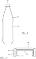
- a preform 10 illustrated in figure 1 can be blow molded to form a container 22 illustrated in figure 2 .
- the container 22 comprises a shell 24 comprising a threaded neck finish 26 defining a mouth 28, a capping flange 30 below the threaded neck finish, a tapered section 32 extending from the capping flange, a body section 34 extending below the tapered section, and a base 36 at the bottom of the container.
- the container 10 is suitably used to make a packaged beverage 38, as illustrated in figure 3 .
- the packaged beverage 38 includes a beverage.
- the beverage may be a carbonated beverage or non-carbonated beverage. Examples of suitable beverages include soda, beer, wine, fruit juices, tea and water. In one particular embodiment, the beverage is an oxygen sensitive beverage.
- the beverage is a vitamin C containing beverage such as a vitamin C containing fruit juice, a beverage which has been fortified with vitamin C, or a combination of juices in which at least one of the juices includes vitamin C.
- the beverage is disposed in the container 22 and a closure 40 seals the mouth 28 of container 22.
- a circular cross-section closure 40 includes a body 42 with a screw-threaded portion 44 for screw-threadedly engaging the closure with threaded neck finish 26.
- a liner 46 comprising a hydrogen generating device which incorporates calcium hydride.
- the liner 46 is disc-shaped and is a friction fit within the body 42 of the closure which has a corresponding circular cross-section.
- the liner 46 is superimposed upon the circular cross-section, and its entire periphery extends to and contacts the circumferential wall of an inner part of the body 42 so that it effectively fills the inner part.
- the liner may be an inference fit within the body 42 and/or may be secured by adhesive or other means. If an adhesive is used, then there is no requirement for the liner to fill the inner part of the body 42.
- the shell 24 of the container includes a catalyst.
- the catalyst may be dispersed in the polymer matrix, for example PET, which defines the shell 24 by injection molding polymeric matrix material and catalyst, for example a palladium compound, to define a preform 10 which is subsequently blow molded to define the container 22.
- the headspace in the container will be saturated with water vapor.
- This vapor passes into liner 46 and contacts the calcium hydride associated with the liner.
- the calcium hydride produces molecular hydrogen which migrates into the polymer matrix of shell 24 and combines with oxygen which may have entered the container through its permeable walls.
- a reaction between the hydrogen and oxygen takes place, catalyzed by the catalyst, and water is produced.
- oxygen which may ingress the container is scavenged and the contents of the container are protected from oxidation.
- the scavenging effect may be maintained for as long as hydrogen is produced in the container and such time may be controlled by inter alia varying the amount of hydride in the liner.
- Examples 1 to 6 describe the compounding of polymeric materials with hydrides;
- Example 7 describes preparation of plaques from compositions prepared;
- Example 8 describes an experiment to compare potential for flavour (e.g. acetaldehyde) scalping of compositions containing sodium borohydride or calcium hydride; and
- Example 9 describes experiments to compare hydrogen generating characteristics of compositions containing sodium borohydride or calcium hydride.
- the respective amounts of sodium borohydride and calcium hydride are selected so that compositions containing them are arranged to deliver the same molar quantities of hydrogen having regard to the molecular weights and formulae of the hydrides.
- 2kg of sodium borohydride was compounded with 23kg of Elvax 550 on a 24mm Prism TSE 24HC twin screw extruder fitted with a die-face cutter.
- the feed zone of the extruder was kept under a nitrogen blanket.
- the feed zone temperature was set at 50°C and the other 10 zones of the extruder were set at 130°C.
- the compound was pelletised and stored in a dry nitrogen atmosphere.
- 3mm thick plaques (6x4cm) were moulded from the sodium borohydride compound using a Boy 22M injection moulder machine at 190°C.
- 2kg of sodium borohydride was compounded with 23kg of Versaflex HCMT555 on a 24mm Prism TSE 24HC twin screw extruder fitted with a die-face cutter.
- the feed zone of the extruder was kept under a nitrogen blanket.
- the feed zone temperature was set at 50°C and the other 10 zones of the extruder were set at 130°C.
- the compound was pelletised and stored in a dry nitrogen atmosphere.
- 3mm thick plaques (6x4cm) were moulded from the sodium borohydride compound using a Boy 22M injection moulder machine at 200°C.
- 2kg of sodium borohydride was compounded with 23kg of LDPE (ExxonMobile LD605BA) on a 24mm Prism TSE 24HC twin screw extruder fitted with a die-face cutter.
- the feed zone of the extruder was kept under a nitrogen blanket.
- the feed zone temperature was set at 50°C and the other 10 zones of the extruder were set at 140°C.
- the compound was pelletised and stored in a dry nitrogen atmosphere.
- 3mm thick plaques (6x4cm) were moulded from the sodium borohydride compound using a Boy 22M injection moulder machine at 190°C.
- 3mm thick plaques were moulded from SEBS (Versaflex HCMT555) using a Boy 22M injection moulder machine at 200°C.
- 26mm discs were cut from moulded plaques prepared in examples 2, 3, 5, 6 and 7. Each disc was placed in a separate 200ml glass bottle. Each bottle was sealed and the atmosphere within the bottle replaced with helium containing 25ppm acetaldehyde (AA) by purging. A 2ml sample of the gas from each bottle was removed and analysed by CG after 12 days and 21 days storage at room temperature. The remaining AA concentration express as percentage of the starting concentration for each example is shown in table 1.
- Rectangular strips (approximately 5cm x 1.5cm) were cut from the moulded plaques prepared in Examples 1 to 6. Each sample was accurately weighed in grams to 2 decimal places. Each sample was wedged into the bottom of a 100 ml graduated, glass gas-burette which was inverted and placed into a water-filled one litre beaker. The burette was filled with water to just below the sample by inserting a 3mm flexible polyethylene tube to the top of the burette and removing the air with a syringe attached to the other end of the polyethylene tube. The hydrogen produced was measured by noting the amount of water displaced from each tube over time.
- example 2 NaBH 4 /SEBS
- example 5 changing the hydride in SEBS from NaBH 4 to CaH 2
- example 6 show that switching to a CaH 2 /LDPE compound retards the loss of AA further - after 21 days storage the lower limit of AA has increased further to 43%.
- acetaldehyde present in a container will be reacted away relatively quickly by sodium borohydride - containing compositions. If the product in the container is for example a fruit juice which generates significant quantities of head space aldehyde-based flavour components, such flavour components may be gradually removed by reaction with sodium borohydride which may detrimentally affect the flavour of the juice. This potential flavour scalping effect is much less likely when calcium hydride containing compositions are used instead of sodium borohydride.
- the CaH 2 /EVA compound (example 2) generated 105 ml/g of hydrogen within 10 days
- the analogous NaBH 4 /EVA compound (example 1) only generated 26ml/g hydrogen after 10 days.
- the appropriate selection of the calcium hydride compound can significantly extend the scope for controlling the rate of hydrogen generation.
- calcium hydride can be used to generate a very rapid initial hydrogen generation rate which can be used to rapidly scavenge the oxygen in the head space of a sealed container and hence stop the degradation of oxygen sensitive materials immediately.
- sodium borohydride can react with some polymers, for example polymers with ester linkage, meaning that compositions of such polymers (e.g. acrylic acid or polyester polymers) cannot be used as hydrogen generating polymer compositions.
- boron compounds that may be present as a result of the hydrogen generation reaction using sodium borohydride may need to be prevented from contacting a beverage in a container with which the borohydride is associated, due to regulatory limitations on consumer exposure to such compounds, whereas such limitations on by-products from calcium hydride are likely to be less restrictive.
Description
- This invention relates to the scavenging of oxygen and particularly, although not exclusively, relates to the scavenging of oxygen in containers, for example food or beverage containers.
- Polymers such as poly(ethylene terephthalate) (PET) are versatile materials that enjoy widespread use for fibres, films and three-dimensional structures. A particularly important application for polymers is for containers, especially for food and beverages. This application has seen enormous growth over the last 20 years, and continues to enjoy increasing popularity. Despite this growth, polymers have some fundamental limitations that restrict their applicability. One such limitation is that all polymers exhibit some degree of permeability to oxygen. The ability of oxygen to permeate through polymers such as PET into the interior of the container is a significant issue, particularly for foods and beverages that are degraded by the presence of even small amounts of oxygen. For the purpose of this disclosure, permeable means diffusion of small molecules through a polymeric matrix by migrating past individual polymer chains, and is distinct from leakage, which is transport through macroscopic or microscopic holes in a container structure.
- Besides food and beverages, other products affected by oxygen include many drugs and pharmaceuticals, as well as a number of chemicals and even electronics. In order to package these oxygen-sensitive products, brand owners have historically relied on the use of glass or metal packaging. More recently, brand owners have begun to package their products in plastic packages which incorporate passive barriers to oxygen and/or oxygen scavengers. Generally, greater success has been achieved utilizing oxygen scavengers; however, oxygen scavenging materials heretofore have suffered from a number of issues. In particular, oxygen scavengers utilized to date rely on the incorporation of an oxidizable solid material into the package. Technologies utilized include oxidation of iron (incorporated either in sachets or in the container sidewall), oxidation of sodium bisulfite, or oxidation of an oxidizable polymer (particularly poly(butadiene) or m-xylylenediamine adipamide). All of these technologies suffer from slow rates of reaction, limited capacity, limited ability to trigger the scavenging reaction at the time of filling the container, haze formation in the package sidewall, and/or discoloration of the packaging material. These problems have limited the use of oxygen scavengers in general, and are especially significant for transparent plastic packaging (such as PET) and/or where recycling of the plastic is considered important.
- Co-pending publication number
WO2008/090354A1 discloses a container comprising an active substance which is incorporated in the container and is arranged to react with moisture in the container to release molecular hydrogen. The document describes a wide range of potential active substances including metals and/or hydrides. Potential hydrides are stated to be inorganic for example comprising a metal hydride or borohydride or they may be organic. In addition, the active substance could comprise a polymeric matrix, for example a polymeric silicon hydride. The document also states that the active material may be embedded in a polymeric matrix at a preferred level of 4-8wt% of active substance. The specific examples in the document focus on use of sodium borohydride as the active material. - One problem associated with use of sodium borohydride is that its initial rate of production of hydrogen can be quite low. This may be disadvantageous since it would be preferable for initial hydrogen production to be at an enhanced rate thereby to scavenge headspace oxygen present in a container after initial filling of the container. The rate may then fall off and be sufficient to scavenge oxygen passing through walls of the container.
- It has also been found that active substances described in
WO2008/090354A , especially sodium borohydride, can react with aldehydes which are important flavour components of foods and beverages. An increased loss of these flavour components by reaction with the active substance may have a detrimental effect on the flavour of the food or beverage - i.e. the flavour is scalped and such scalping may get worse over time. In addition, boron compounds, unless suitably restrained, may migrate into foods or beverages. Such migration needs to be monitored in order to ensure compliance with any applicable regulatory limits applicable to boron compounds. Furthermore, it has been found that it may be difficult to incorporate some active substances such as sodium borohydride with certain polymers due to a reaction between the borohydride and the polymer. - It is an object of the present invention to address the above described problems.
- According to a first aspect of the invention, there is provided a hydrogen-generating composition comprising calcium hydride associated with a matrix material, as defined in claim 1.
- Said calcium hydride may be embedded or preferably dispersed in said matrix material. Said matrix material may comprise a polymeric matrix material, selected based on the solubility of moisture in the bulk polymer and which is suitably chemically inert to the calcium hydride. Suitable matrix materials have a water vapour permeability of greater than 0.2 g.mm/m2.day, suitably greater than 0.4 g.mm/m2.day, preferably greater than 0.6 g.mm/m2.day, more preferably greater than 0.8 g.mm/m2.day, and especially greater than 1.0 g.mm/m2.day. Said matrix material may comprise a blend comprising at least two polymeric materials.
- The water vapour permeability of a matrix material in said composition may be less than 5 g.mm/m2.day, less than 4 g.mm/m2.day or less than 3 g.mm/m2.day.
- The matrix material in said composition preferably comprises an organic polymer. It may comprise a blend of more than one polymer. It preferably comprises, more preferably consists essentially of, a thermoplastic polymeric material.
- Unless otherwise stated, water permeability described herein is measured using (American Society for Testing Materials Annual Book of Standards) ASTM procedure E96 Procedure E at 38°C and relative humidity of 90%.
- Suitable polymeric matrix materials include but are not limited to polyolefin homopolymers, random or block copolymers such as polyethylene and ethylene copolymers, polypropylene and propylene copolymers, butylene copolymers, ethylene vinyl acetate polymers and copolymers, styrene-ethylene-butylene-styrene copolymers, polystyrene and styrene polymers and copolymers, polyesters, for example terephthalates such as polybutylene terephthalate, polyurethanes, (meth)acrylic ester copolymers and nylon 6.
- The particle size and particle size distribution described herein may be measured by methods such as those described in Size Measurement of Particles entry of Kirk-Othmer Encyclopedia of Chemical Technology, Vol. 22, 4th ed., (1997) pp. 256-278, incorporated herein by reference. For example, particle size and particle size distributions may be determined using a Fisher Subsieve Sizer or a Microtrac Particle-Size Analyzer manufactured by Leeds and Northrop Company, or by microscope techniques, such as scanning electron microscopy or transmission electron microscopy.
- Calcium hydride of said composition may be in the form of a finely divided powder, preferably with a median particle size from about 0.5µm to 500µm, more preferably from about 1µm to 300µm and especially from about 3µm to 200µm. [As used herein, a d50 particle size is the median diameter, where 50% of the volume is composed of particles larger than the stated d50, and 50% of the volume is composed of particles smaller than the stated d50 value. As used herein, the median particle size is the same as the d50 particle size.]
- To exercise additional control on the rate and release of hydrogen from the calcium hydride of said composition, it may be useful control to the particle size distribution of the calcium hydride particles.
- A range of particle size distributions may be useful. The particle size distribution, as used herein, may be expressed by the "span (S)," where S is calculated by the following equation:

- Particle size distributions of calcium hydride particles in which the span is less than 10, or less than 5 or less than 2 for example may be used. Alternatively, the particle size distribution (S) may range even broader, such as less than 15, less than 25 or less than 50.
- Said calcium hydride is one active substance in said composition which is arranged to release molecular hydrogen as a result of contact with water. Said hydrogen generating composition may include calcium hydride and an additional active substance arranged to release molecular hydrogen as a result of contact with water. A said additional active substance may a metal or a hydride. It may be selected from sodium metal, lithium metal, potassium metal, sodium hydride, lithium hydride, potassium hydride, magnesium hydride, sodium borohydride and lithium aluminum hydride.
- Calcium hydride suitably makes up at least 50wt%, at least 60wt%, at least 70wt%, at least 80wt% or at least 90wt% of the total active substance(s) in said hydrogen-generating composition which are arranged to release molecular hydrogen as a result of contact with water. Preferably, calcium hydride represents more than 95wt% or more than 98wt% of the active substance(s) in said composition which are arranged to release molecular hydrogen as a result of contact with water. Preferably, calcium hydride is the only active substance in said composition which is arranged to release molecular hydrogen as a result of contact with water.
- The composition may include less than 70wt% of said active substances.
- In a preferred embodiment, the sum of the amount(s) of active substance(s) in said hydrogen composition which are arranged to release molecular hydrogen on contact with water is more than 17wt%. The sum of the amount(s) is preferably less than 50wt%, less than 40wt%, less than 30wt% or less than 25wt%.
- In a preferred embodiment, said hydrogen-generating composition includes more than 16wt% or more than 17wt% of calcium hydride. Said composition may include more than 17 - 40 wt.% suitably more than 17 to 30wt%, preferably more than 17 to 25wt% of calcium hydride.
- Said hydrogen-generating composition may include at least 60wt%, suitably at least 70wt%, preferably at least 75wt% of matrix material, wherein the matrix material may comprise one or more organic polymers as described. Said composition may include less than 98wt%, less than 95wt%, less than 90wt% or 83.5wt% or less of matrix material.
- In said composition, the sum of the amounts of matrix material and active substance(s) which are arranged to release molecular hydrogen on contact with water is suitably at least 85wt%, preferably at least 90wt%, more preferably at least 95wt%, especially at least 98wt%. The balance of material in the hydrogen generating composition may comprise additives to aid the compounding and effective dispersion of the calcium hydride in the matrix material, such as dispersants, surfactants, stabilizers and plasticizers. In addition, other conventional additives such as colorants (pigments and dyes), lubricants, and slip agents may be included in the hydrogen-generating composition to modify the physical and performance properties of the composition.
- The sum of the amounts of matrix material and calcium hydride in said composition is suitably at least 85wt%, preferably at least 90wt%, more preferably at least 95wt%, especially at least 98wt%.
- In said hydrogen-generating composition, a first ratio defined as the sum of the wt% of matrix material divided by the sum of the wt% of active substance(s) which is/are arranged to generate molecular hydrogen on contact with water is preferably at least 2, more preferably at least 3, especially at least 4. Said first ratio may be less than 20. Said first ratio may be in the range 2-16, preferably 3-12, more preferably 3-8, especially 3-6.
- In said hydrogen generating composition, a second ratio defined as the sum of the wt% of matrix material divided by the wt% of calcium hydride is preferably at least 2, more preferably at least 3, especially at least 4. Said second ratio may be less than 20. Said second ratio may be in the range 2-16, preferably 3-12, more preferably 3-8, especially 3-6.
- In a preferred embodiment, said hydrogen generating composition comprises more than 17 - 30 wt.% of calcium hydride and 70 - less than 83 wt.% of matrix material.
- In some cases, said hydrogen-generating compositions may include a catalyst to facilitate a reaction between molecular hydrogen and molecular oxygen as hereinafter described. The catalyst may be incorporated in the matrix material
- The composition of the first aspect may be in the form of pellets or granules for use in making hydrogen-generating components. The composition may be in sheet form. The composition may be in the form of a component having a volume in the range 0.1 to 5cm3, suitably in the range 0.1 to 3cm3, preferably in the range 0.2 to 2cm3.
- According to a second aspect of the invention, there is provided a method of making a composition according to the first aspect, the method comprising contacting calcium hydride and matrix material.
- Calcium hydride could be pre-dispersed into a carrier medium prior to mixing with the matrix material to improve the dispersion of the particulate matter in the composition. A further advantage of incorporating the hydride into an inert carrier is that its reactivity decreases significantly. This is because the reactive particulates are surrounded by a hydrophobic carrier phase which slows down reaction with water (via atmospheric exposure or otherwise).
- Suitable carriers include dry non-aqueous media that do not react with the hydride to release hydrogen and are liquid at room temperature. Examples include dried hydrocarbon-based mineral oils, silicone based oils, and alkyl terminated glycols (e.g. alkyl terminated PEG, PPG, THF). The carrier is preferably fully compatible with the final polymer matrix in order to fully disperse the hydride. The carrier may have a boiling point such that it can be removed during the compounding stage so as not to affect the properties of the final compound. The carrier may be a polymerisable monomer or oligomer which during the compounding stage undergoes polymerization and defines the polymeric matrix at least in part.
- To improve the dispersion of calcium hydride throughout the matrix during compounding, it can be advantageous to use a suitable dispersant. Suitable dispersants should be effectively free of moisture and should not chemically react with calcium hydride to release hydrogen during the compounding process. Ideally, the dispersant molecule should contain a moiety capable of interacting or absorbing onto the calcium hydride particle surface and a moiety that is soluble in the polymer matrix. The dispersant molecule suitably does not include chemical groups that can react with calcium hydride to form hydrogen during compounding, for example, dispersants free of reactive carboxylic acid groups or reactive O-H bonds are preferred. Examples of suitable dispersants include, fatty acid esters of polyethylene glycol (PEG), polypropylene glycol (PPG), and dialkyl terminated PEG.
- The dispersant can be present at a concentration of 0 - 10 wt% in a formulation compounded to produce the hydrogen-generating composition. The dispersant is suitably added to the carrier/particulate mix under high shear to ensure that primary particles are obtained.
- When the hydrogen-generating composition includes a catalyst, the method may comprise incorporating the catalyst into the matrix material.
- The large amount of inorganic particulate matter added to the matrix may alter the physical properties of the matrix. The inorganic filler may reinforce the matrix, making it stiffer, which may adversely impact on the ability of the material to form flexible sheet material. Therefore, a plasticizer may be added to the formulation compounded to produce the hydrogen-generating composition in order to improve the flexibility of the hydrogen-generating composition produced. A plasticizer is suitably non-reactive and contains no groups with OH bonds. Examples of common plasticizer that may be used include: adipate, phthalate, sebecate, maleates, benzoates, trimellitate. Epoxidised vegetable oils, polybutene, or other polymeric plasticizers may be used to prevent adverse reactions with hydride.
- The method may comprise extruding or moulding the composition into a shape which can be incorporated into a packaging container. The composition may be molded (e.g. compression molded), stamped or laminated to another component of a packaging container, for example a closure device.
- Prior to use in making a component for incorporating in a container, it is preferred to store the hydrogen-generating composition of the first aspect in an environment wherein moisture is restricted from reacting prematurely with the calcium hydride. Thus, in a third aspect, there is provided a package containing a hydrogen-generating composition according to the first aspect, wherein the package is arranged to restrict passage of moisture to the calcium hydride in the composition.
- The package may include an inert gas or a mixture of an inert gas and hydrogen gas. Alternatively, the package may comprise essentially a vacuum in which the composition is arranged.
- According to a fourth aspect of the invention, there is provided a container comprising a hydrogen generating means which comprises a hydrogen-generating composition according to the first aspect.
- The hydrogen generating means may be arranged to slowly release molecular hydrogen inside the container over an extended period of time. In the presence of a suitable catalyst, the molecular hydrogen will react with any oxygen present in the interior of the container or in the container wall. Preferably, the rate of hydrogen release is tailored to match the rate of oxygen ingress into the container. In addition, it is preferable for there to be an initial relatively rapid release of hydrogen, followed by a slow continual release over a period of months or even years. Furthermore, it is preferred that substantial release of hydrogen reliably begins only when the package is filled. Finally, it is preferable that the substance releasing hydrogen does not adulterate the contents of the container.
- The container suitably includes a catalyst for catalyzing a reaction between said molecular hydrogen and molecular oxygen. As a result, molecular oxygen in said container, for example which passes into said container through a wall thereof, may be scavenged, with water as a byproduct.
- For purposes of this disclosure, a container includes any package that surrounds a product and that contains no intentional microscopic or macroscopic holes that provide for transport of small molecules between the interior and the exterior of the package. Said container optionally comprises a closure. For purposes of this disclosure, a catalyst includes any substance that catalyzes or promotes a reaction between molecular hydrogen and molecular oxygen.
- The container may include a sidewall constructed from a composition that includes a polymer resin first component and a second component comprising a catalyst capable of catalyzing a reaction between molecular hydrogen and molecular oxygen. The hydrogen generating means is preferably located within the container or near an interior surface of the container. The hydrogen generating means is preferably located in or on a closure of said container.
- The hydrogen generating means may be associated with a container in a variety of ways. Where a container includes a removable part, for example a closure, it may conveniently be associated with the closure. A closure may be releasably securable to a container body so that it can be removed and replaced, for example by being screw-threaded; or may be arranged to be removed but not replaced, for example by comprising a film which is adhered to a container body. In the latter case, the closure may comprise a film comprising a flexible "lidding" material as described hereinafter. In one embodiment, a container may include both a film closure which may provide an aseptic seal for the container and a releasably securable closure, both of which may independently include hydrogen generating means. After initial removal of both the releasably securable closure and the film closure, the releasably securable closure may be replaced and may generate hydrogen and therefore improve the storage life of the contents of the container.
- When hydrogen generation occurs by reaction of the active substance with water, initiation of substantial hydrogen generation will occur only when the hydrogen generator is placed in a moisture-containing environment such as that found in most oxygen-sensitive foods and beverages. Thus initiation of hydrogen generation generally will coincide with the filling of the container and/or placement of the hydrogen generator into or near the interior of the container. In order to prevent or minimize hydrogen generation before this time, it is sufficient to minimize contact of the hydrogen generator with moisture. Unlike exclusion of molecular oxygen, exclusion of moisture is readily achieved by a number of methods, including but not limited to packaging the hydrogen generator and/or the structures containing the hydrogen generator in metal foil, metalized plastic, or polyolefin bags. For example, bulk packaging of closures containing hydrogen generating means in sealed polyethylene bags is an expedient way of limiting hydrogen generation prior to placement of the individual closures onto containers. Another method to limit contact of the hydrogen generator with moisture prior to placement of the individual closures onto containers is to place one or more desiccants inside the packaging with the closures.
- Whilst in preferred embodiments, the source of moisture in the container for initiating hydrogen generation is a food or beverage contained within the container; other sources of moisture are contemplated. For example, a moisture generating means separate from the food or beverage may be associated with the container. Such a moisture generating means suitably comprises a high level of moisture. It may comprise a hydrogel which is associated with and/or is part of the container or another component within the container (e.g. a hydrated salt) which releases moisture on drying or in response to another stimulus, heating, exposure to visible or UV radiation, pressure change, microwave radiation, pH, electrical, magnetic field, ultrasound, etc.
- Because once released the molecular hydrogen will rapidly disperse throughout the interior of the container and permeate through all permeable portions of the container walls, the location of the hydrogen generating means within the container is not critical. In general, however, it is desirable to locate the hydrogen generating means within the interior of the container in order to maximize the amount of hydrogen that is available for oxygen scavenging and minimize the amount of hydrogen generator required to obtain the desired degree of oxygen scavenging. Within the container, it is generally preferred to locate the hydrogen generating means in an opaque portion of the container. For example, in a beverage container made of transparent PET, location of the hydrogen generating means within the container closure is preferred. It is also generally preferred to locate the hydrogen generator behind a control means of a type described hereinafter.
- In one embodiment, the hydrogen generating means may be incorporated in a film which is part of a container and is arranged to be removed (and suitably not replaced) to allow access to the contents of the container. The film may comprise a laminate. It may include a layer which is substantially impermeable to oxygen for example a metal layer such as an aluminum layer. The film may include a hydrogen generating layer which includes a said hydrogen generating means. The distance between the hydrogen generating layer and the contents of the container is preferably less than the distance between a said impermeable layer of the film and the contents of the container. The film may include a layer which defines a said control means, wherein the distance between the layer which defines a said control means and the contents of the container is less than the distance between the hydrogen generating layer and the contents of the container. The film may be a lidding foil which is adhered to a container body to define a container.
- Because the generated hydrogen will permeate through the container walls, the amount of hydrogen present within the container at any time is minimal. Moreover, the faster hydrogen is generated the faster it will permeate; hence significant increases in the rate of hydrogen generation (from, for example, increased container storage temperatures) will result in only modest increases in the concentration of hydrogen within the container. Because the permeability of hydrogen through a polymer is much greater than the permeability of oxygen, the amount of hydrogen in the headspace of the container may not need to exceed 4 volume percent, which is below the flammability limit for hydrogen in air. Furthermore, the solubility of hydrogen in food or beverages is low; hence at any time most of the hydrogen in the container will be in the headspace of the container. Hence, the amount of hydrogen that may be present within a container may be very small. For example, for a 500 ml PET beverage container with a 30 milliliter headspace volume and a 0.05 cc/package-day O2 ingress rate, less than about 1 cc of hydrogen is needed within the container in order for the rate of H2 permeation to be greater than the rate of oxygen ingress. In addition, the rate of H2 generation would need to be only about 0.1-0.2 cc/day in order for enough hydrogen to be generated on an ongoing basis to react with most or all of the ingressing oxygen.
- Because only small amounts of hydrogen need to be present inside the container in order to achieve high levels of oxygen scavenging, expansion and contraction of the container over time from the presence (or loss) of hydrogen is minimal. Consequently this technology is readily applicable to both rigid and flexible containers.
- In order to facilitate the reaction between molecular hydrogen with molecular oxygen, a catalyst is desired. A large number of catalysts are known to catalyze the reaction of hydrogen with oxygen, including many transition metals, metal borides (such as nickel boride), metal carbides (such as titanium carbide), metal nitrides (such as titanium nitride), and transition metal salts and complexes. Of these, Group VIII metals are particularly efficacious. Of the Group VIII metals, palladium and platinum are especially preferred because of their low toxicity and extreme efficiency in catalyzing the conversion of hydrogen and oxygen to water with little or no byproduct formation. The catalyst is preferably a redox catalyst.
- In order to maximize the efficiency of the oxygen scavenging reaction, it is preferable to locate the catalyst where reaction with oxygen is desired. For example, if the application requires that oxygen be scavenged before it reaches the interior of the container, incorporation of the catalyst in the package sidewall is desirable. Conversely, if scavenging of oxygen already present in the container is desired, it is generally preferable to locate the catalyst near or in the interior of the container. Finally, if both functions are desired, catalyst may be located both in the interior of the container and in the container walls. While the catalyst may be directly dispersed into the food or beverage, it is generally preferable that the catalyst be dispersed into a polymeric matrix. Dispersion of the catalyst into a polymeric matrix provides several benefits, including but not limited to minimization of food or beverage adulteration, minimization of catalyzed reaction between molecular hydrogen and food or beverage ingredients, and ease of removal and/or recycling of the catalyst from the food or beverage container.
- A particular advantage of the present invention is that because of the extremely high reaction rates obtainable with a number of catalysts, very small amounts of catalyst may be required. A container may include 0.01 ppm to 1000ppm, suitably 0.01ppm to 100ppm, preferably 0.1ppm to 10ppm, more preferably at least 0.5ppm of catalyst relative to the weight of said container (excluding any contents thereof). In preferred embodiments, 5ppm or less of catalyst is included. Unless otherwise stated reference to "ppm" refer to parts per million parts by weight.
- The small amount of catalyst needed allows even expensive catalysts to be economical. Moreover, because very small amounts are required to be effective, there can be minimal impact on other package properties, such as color, haze, and recyclability. For example, when palladium is utilized as the catalyst, concentrations less than about 5 ppm of finely dispersed Pd may be sufficient to achieve acceptable rates of oxygen scavenging. In general, the amount of catalyst required will depend on and can be determined from the intrinsic rate of catalysis, the particle size of the catalyst, the thickness of the container walls, the rates of oxygen and hydrogen permeation, and the degree of oxygen scavenging required.
- In order to maximize the efficacy of the catalyst, it is preferred that the catalyst be well dispersed. The catalyst can be either homogenous or heterogeneous. For homogeneous catalysts it is preferred that the catalysts be dissolved in a polymer matrix at a molecular level. For heterogeneous catalysts, it is preferred that the average catalyst particle size be less than 1 micron, more preferred that average catalyst particle size be less than 100 nanometers, and especially preferred than the average catalyst particle size be less than 10 nanometers. For heterogeneous catalysts, the catalyst particles may be free-standing, or be dispersed onto a support material such as carbon, alumina, or other like materials.
- The method of incorporation of the catalyst is not critical. Preferred techniques result in a well dispersed, active catalyst. The catalyst can be incorporated into the container at any time prior to, during, or after the introduction of the hydrogen source. The catalyst can be incorporated into a polymeric matrix during polymer formation or during subsequent melt-processing of the polymer. It can be incorporated by spraying a slurry or solution of the catalyst onto polymer pellets prior to melt processing. It can be incorporated by injection of a melt, solution, or suspension of the catalyst into pre-melted polymer. It may also be incorporated by making a masterbatch of the catalyst with polymer and then mixing the masterbatch pellets with polymer pellets at the desired level before injection molding or extrusion. In containers wherein the catalyst is located in the interior of the container, the catalyst may be co-mingled with the active substance in the matrix of the hydrogen generator.
- In a preferred embodiment, the catalyst is incorporated into a wall of the container. It is preferably associated with, for example dispersed in, a polymer which defines at least part of the wall of the container. In a preferred embodiment, the catalyst is associated with material which defines at least 50%, preferably at least 75%, more preferably at least 90% of the area of the internal wall of the container.
- In a preferred embodiment, the catalyst is distributed substantially throughout the entire wall area of a container, optionally excluding a closure thereof.
- The containers contemplated in the present invention may be either of a monolayer or a multilayer construction. In a multi-layered construction, optionally one or more of the layers may be a barrier layer. A non-limiting example of materials which may be included in the composition of the barrier layer are polyethylene co-vinyl alcohols (EVOH), poly(glycolic acid), and poly(metaxylylenediamine adipamide). Other suitable materials which may be used as a layer or part of one or more layers in either monolayer or multilayer containers include polyester (including but not limited to PET), polyetheresters, polyesteramides, polyurethanes, polyimides, polyureas, polyamideimides, polyphenyleneoxide, phenoxy resins, epoxy resins, polyolefins (including but not limited to polypropylene and polyethylene), polyacrylates, polystyrene, polyvinyls (including but not limited to poly(vinyl chloride)) and combinations thereof. Furthermore glassy interior and/or exterior coatings (SiOx, aluminum, Al2O3 or amorphous carbon) are explicitly contemplated as barrier layers. All of the aforementioned polymers may be in any desired combination thereof. Any and all of these materials may also comprise the container closure. In some cases, a container may comprise glass.
- In a preferred embodiment, the container includes walls defined by polyester, for example PET and preferably catalyst is dispersed within the polyester.
- The shape, construction, or application of the containers used in the present invention is not critical. In general, there is no limit to the size or shape of the containers. For example, the containers may be smaller than 1 milliliter or greater than 1000 liter capacity. The container preferably has a volume in the range 20ml to 100 liter, more preferably 100ml to 5 liter. Similarly, there is no particular limit to the thickness of the walls of the containers, the flexibility (or rigidity) of the containers, or the intended application of the containers. It is expressly contemplated that the containers include but are not limited to sachets, bottles, jars, bags, pouches, trays, pails, tubs, barrels, blister packs, or other like containers. Furthermore, the container may be located in the interior of another container, or have one of more containers located in the interior of the container. In preferred embodiments, the container may be any sealable container (plastic, glass, metal or hybrid construction) and may include sealable single and multilayer tray constructions (injection moulded or thermoformed), multi layer bags or pouches.
- Said container may be arranged to protect an article from corrosion by scavenging oxygen within a container which contains an article susceptible to corrosion. The container may be used to protect sensitive electronic components or devices.
- Said container may include a permeable wall comprising of one or more polymers that have in the absence of any oxygen scavenging a permeability between about 6.5x10⁻⁷ cm3-cm/(m2-atm-day) and about 1x104cm3-cm/(m2-atm-day).
- It is generally desirable to tailor the length of time hydrogen will be released from the hydrogen generator to be similar to or greater than the desired shelf-life of the product that is to be protected from oxygen ingress. Tailoring the length of time hydrogen will be released can be done by adjusting properties of the control means and/or polymeric matrix. It is also desirable to tailor the rate of hydrogen generation to be equal to or somewhat greater than two times the rate of oxygen ingress, since the overall reaction is 2 H2 + O2 → 2 H2O.
- The hydrogen generating means is suitably arranged to generate hydrogen for an extended period of time, for example at least 100 days, preferably at least 180 days, more preferably at least 270 days, especially at least 365 days. The aforementioned periods may be assessed after storage at room temperature (22°C) and ambient pressure.
- It may also be preferred to scavenge oxygen that is initially present in the container or the food or beverage. To do so it is preferred that the hydrogen generator initially release hydrogen at an enhanced rate. In these instances, it is also preferred that a catalyst be located in or near the interior of the container.
- The container may include a product, which suitably includes a source of moisture. The product may be for human consumption; it may be a food or beverage, the latter being especially preferred.
- As referred to above, the container may include a control means for controlling passage of moisture from the container to the hydrogen generating means.
- Said control means is preferably arranged to control passage of moisture suitably so as to reduce the rate of hydrogen generation by said hydrogen generating means compared to the rate in the absence of said control means. In this case, the control means suitably defines the rate determining step for passage of moisture to the active material of the hydrogen generating means, rather than the rate determining step being defined by other features of the hydrogen generating means, for example the properties of a matrix material hereinafter described with which the active material may be associated.
- Providing a control means as described introduces substantial flexibility which allows control of the rate of production of hydrogen by the hydrogen generating means and tailoring of the time over which hydrogen is generated, which determines the shelf-life of the container. For example, to achieve a long shelf-life a relatively large amount of active material may be associated with a matrix and by controlling passage of moisture to the hydrogen generating means, the rate of hydrogen generation is controlled as is the rate of consumption of the active material. In contrast, in the absence of the control means, the relatively large amount of active material would produce hydrogen at a quicker rate and would be consumed quicker meaning the shelf-life of the container would be less.
- Said control means may comprise a layer of material, for example polymeric material, having a water vapour permeability of less than 2.0 g.mm/m2.day, suitably less than 1.5 g.mm/m2.day, preferably less than 0.8 g.mm/m2.day, more preferably less than 0.4 g.mm/m2.day.
- Said control means may comprise a layer or multiple layers of polymeric material selected from polyolefin homopolymers, random or block copolymers (e.g. HDPE, PP, LDPE,) PET, EVA, SEBS and Nylon (e.g. Nylon-6).
- Said control means may comprise one or more layers of material, for example polymeric material, having a total thickness of at least 0.010mm, preferably at least 0.025mm, more preferably at least 0.045mm. The thickness may be less than 0.5mm, 0.2mm or 0.1mm.
- Various means may be used to define control means for controlling passage of moisture. In one embodiment, said control means may comprise a layer of material (e.g. sheet material) which is suitably positioned between said hydrogen generating means and a source of moisture in the container. Said layer of material suitably comprises a polymeric material, as aforesaid. The layer may be adhered to the hydrogen-generating means or may contact it directly, for example by virtue of being co-extruded therewith.
- The control means may have a thickness of at least 0.010mm, preferably at least 0.025mm, more preferably at least 0.045mm. The thickness may be less than 0.5mm, 0.2mm or 0.1mm.
- The material, for example polymeric material of the control means is suitably permeable to hydrogen and water vapour. Preferably, it is impermeable to by-products of the hydrogen generating means which could migrate into the container.
- According to a fifth aspect of the invention, there is provided a closure for a container, said closure comprising a hydrogen-generating composition according to the first aspect. The closure may include a control means as described herein.
- According to a sixth aspect of the invention, provided the use of calcium hydride for generating a rapid initial hydrogen generation rate in a container in which a hydrogen-generating composition of the first aspect is incorporated.
- Any feature of any aspect of any invention or embodiment described herein may be combined with any feature of any aspect of any other invention or embodiment described herein mutatis mutandis.
- Specific embodiments of the invention will now be described, by way of example, with reference to the accompanying drawings, in which:
-
Figure 1 is a cross-section through a preform; -
Figure 2 is a cross-section through a bottle; -
Figure 3 is a side elevation of a bottle including a closure; -
Figure 4 is a closure, partly in cross-section. - The following materials are referred to hereinafter.
- Ethylene vinyl acetate copolymer (15% vinylacetate content) - Elvax 550 supplied by DuPont. Low density polyethylene (LDPE) - LD605BA supplied by ExxonMobil. Styrene-ethylene-butylene-styrene block copolymer - Versaflex HCMT555 supplied by GLS Corporation.
Sodium Borohydride (Venpure SF) from Rohm & Hass.
Calcium hydride (purity 99%) from Sigma-Aldrich. - A
preform 10 illustrated infigure 1 can be blow molded to form acontainer 22 illustrated infigure 2 . Thecontainer 22 comprises ashell 24 comprising a threadedneck finish 26 defining amouth 28, a cappingflange 30 below the threaded neck finish, a taperedsection 32 extending from the capping flange, abody section 34 extending below the tapered section, and a base 36 at the bottom of the container. Thecontainer 10 is suitably used to make a packagedbeverage 38, as illustrated infigure 3 . The packagedbeverage 38 includes a beverage. The beverage may be a carbonated beverage or non-carbonated beverage. Examples of suitable beverages include soda, beer, wine, fruit juices, tea and water. In one particular embodiment, the beverage is an oxygen sensitive beverage. In another embodiment, the beverage is a vitamin C containing beverage such as a vitamin C containing fruit juice, a beverage which has been fortified with vitamin C, or a combination of juices in which at least one of the juices includes vitamin C. In this embodiment, the beverage is disposed in thecontainer 22 and aclosure 40 seals themouth 28 ofcontainer 22. - Referring to
figure 4 , acircular cross-section closure 40 includes abody 42 with a screw-threadedportion 44 for screw-threadedly engaging the closure with threadedneck finish 26. Inwards of theportion 44 is aliner 46 comprising a hydrogen generating device which incorporates calcium hydride. Theliner 46 is disc-shaped and is a friction fit within thebody 42 of the closure which has a corresponding circular cross-section. Thus, theliner 46 is superimposed upon the circular cross-section, and its entire periphery extends to and contacts the circumferential wall of an inner part of thebody 42 so that it effectively fills the inner part. - As an alternative to it being a friction fit, the liner may be an inference fit within the
body 42 and/or may be secured by adhesive or other means. If an adhesive is used, then there is no requirement for the liner to fill the inner part of thebody 42. - The
shell 24 of the container includes a catalyst. The catalyst may be dispersed in the polymer matrix, for example PET, which defines theshell 24 by injection molding polymeric matrix material and catalyst, for example a palladium compound, to define apreform 10 which is subsequently blow molded to define thecontainer 22. - In use, with
container 22 including a beverage andclosure 40 in position, the headspace in the container will be saturated with water vapor. This vapor passes intoliner 46 and contacts the calcium hydride associated with the liner. As a result, the calcium hydride produces molecular hydrogen which migrates into the polymer matrix ofshell 24 and combines with oxygen which may have entered the container through its permeable walls. A reaction between the hydrogen and oxygen takes place, catalyzed by the catalyst, and water is produced. Thus, oxygen which may ingress the container is scavenged and the contents of the container are protected from oxidation. The scavenging effect may be maintained for as long as hydrogen is produced in the container and such time may be controlled by inter alia varying the amount of hydride in the liner. - As described above calcium hydride is used in the hydrogen generating device described herein. The examples hereinafter describe the preparation of compositions containing hydrides and compare features of calcium hydride with sodium borohydride (which is the focus of
WO2008/090354 ). - Examples 1 to 6 describe the compounding of polymeric materials with hydrides; Example 7 describes preparation of plaques from compositions prepared; Example 8 describes an experiment to compare potential for flavour (e.g. acetaldehyde) scalping of compositions containing sodium borohydride or calcium hydride; and Example 9 describes experiments to compare hydrogen generating characteristics of compositions containing sodium borohydride or calcium hydride.
- In the examples, the respective amounts of sodium borohydride and calcium hydride are selected so that compositions containing them are arranged to deliver the same molar quantities of hydrogen having regard to the molecular weights and formulae of the hydrides.
- 2kg of sodium borohydride was compounded with 23kg of Elvax 550 on a 24mm Prism TSE 24HC twin screw extruder fitted with a die-face cutter. The feed zone of the extruder was kept under a nitrogen blanket. The feed zone temperature was set at 50°C and the other 10 zones of the extruder were set at 130°C. The compound was pelletised and stored in a dry nitrogen atmosphere. 3mm thick plaques (6x4cm) were moulded from the sodium borohydride compound using a Boy 22M injection moulder machine at 190°C.
- 2kg of sodium borohydride was compounded with 23kg of Versaflex HCMT555 on a 24mm Prism TSE 24HC twin screw extruder fitted with a die-face cutter. The feed zone of the extruder was kept under a nitrogen blanket. The feed zone temperature was set at 50°C and the other 10 zones of the extruder were set at 130°C. The compound was pelletised and stored in a dry nitrogen atmosphere. 3mm thick plaques (6x4cm) were moulded from the sodium borohydride compound using a Boy 22M injection moulder machine at 200°C.
- 2kg of sodium borohydride was compounded with 23kg of LDPE (ExxonMobile LD605BA) on a 24mm Prism TSE 24HC twin screw extruder fitted with a die-face cutter. The feed zone of the extruder was kept under a nitrogen blanket. The feed zone temperature was set at 50°C and the other 10 zones of the extruder were set at 140°C. The compound was pelletised and stored in a dry nitrogen atmosphere. 3mm thick plaques (6x4cm) were moulded from the sodium borohydride compound using a Boy 22M injection moulder machine at 190°C.
- 2kg of calcium hydride was compounded with 9.1kg of Elvax 550 on a 24mm Prism TSE 24HC twin screw extruder fitted with a die-face cutter. The feed zone of the extruder was kept under a nitrogen blanket. The feed zone temperature was set at 50°C and the other 10 zones of the extruder were set at 130°C. The compound was pelletised and stored in a dry nitrogen atmosphere. 3mm thick plaques (6x4 cm) were moulded from the calcium hydride compound using a Boy 22M injection moulder machine at 190°C.
- 2kg of calcium hydride was compounded with 9.1kg of Versaflex HCMT555 on a 24mm Prism TSE 24HC twin screw extruder fitted with a die-face cutter. The feed zone of the extruder was kept under a nitrogen blanket. The feed zone temperature was set at 50°C and the other 10 zones of the extruder were set at 130°C. The compound was pelletised and stored in a dry nitrogen atmosphere. 3mm thick plaques (6x4 cm) were moulded from the calcium hydride compound using a Boy 22M injection moulder machine at 200°C.
- 2kg of calcium hydride was compounded with 9.1kg of LDPE (ExxonMobile LD605BA) on a 24mm Prism TSE 24HC twin screw extruder fitted with a die-face cutter. The feed zone of the extruder was kept under a nitrogen blanket. The feed zone temperature was set at 50°C and the other 10 zones of the extruder were set at 190°C. The compound was pelletised and stored in a dry nitrogen atmosphere. 3mm thick plaques (6x6cm) were moulded from the calcium hydride compound using a Boy 22M injection moulder machine at 190°C.
- 3mm thick plaques were moulded from SEBS (Versaflex HCMT555) using a Boy 22M injection moulder machine at 200°C.
- 26mm discs were cut from moulded plaques prepared in examples 2, 3, 5, 6 and 7. Each disc was placed in a separate 200ml glass bottle. Each bottle was sealed and the atmosphere within the bottle replaced with helium containing 25ppm acetaldehyde (AA) by purging. A 2ml sample of the gas from each bottle was removed and analysed by CG after 12 days and 21 days storage at room temperature. The remaining AA concentration express as percentage of the starting concentration for each example is shown in table 1.
Table 1 Example Compound Hydride content (wt%) Acetaldehyde (wt%) remaining after 12 day 21 days 7 (control) SEBS 0 91 91 2 NaBH4/SEBS 8 0 0 5 CaH2/ SEBS 18 18 14 3 NaBH4/LDPE 8 27 8 6 CaH2/ LDPE 18 55 43 - Rectangular strips (approximately 5cm x 1.5cm) were cut from the moulded plaques prepared in Examples 1 to 6. Each sample was accurately weighed in grams to 2 decimal places. Each sample was wedged into the bottom of a 100 ml graduated, glass gas-burette which was inverted and placed into a water-filled one litre beaker. The burette was filled with water to just below the sample by inserting a 3mm flexible polyethylene tube to the top of the burette and removing the air with a syringe attached to the other end of the polyethylene tube. The hydrogen produced was measured by noting the amount of water displaced from each tube over time. The hydrogen gas evolution results for examples 1 to 6, expressed as ml of gas per gram of sample (ml/g) are shown in table 2.
Table 2 Example Compound H2 gas generation (ml/g) after x days 5 10 20 30 40 50 60 70 1 NaBH4(8%)/EVA 17 26 44 63 73 82 92 99 2 NaBH4(8%)/SEBS 17 25 40 59 57 63 72 77 3 NaBH4(8% )/LDPE 9 15 25 35 39 44 49 51 4 CaH2(18%)/EVA 75 105 146 175 196 210 221 221 5 CaH2(18%)/SEBS 65 100 150 183 209 225 232 232 6 CaH2(18%)/LDPE 25 37 50 62 69 75 84 88 - Referring to table 1, it should be noted that the example 2 (NaBH4/SEBS) compound reduces the AA concentration within the bottle to zero after less than 10 days storage, whereas, changing the hydride in SEBS from NaBH4 to CaH2 (example 5) significantly retards the reduction in AA consumption - after 21 days storage the reduction in AA level approaches a lower limit of 14%. Example 6 show that switching to a CaH2/LDPE compound retards the loss of AA further - after 21 days storage the lower limit of AA has increased further to 43%. These results illustrate that there is a very significant risk that any head space aldehydes (e.g. acetaldehyde) present in a container will be reacted away relatively quickly by sodium borohydride - containing compositions. If the product in the container is for example a fruit juice which generates significant quantities of head space aldehyde-based flavour components, such flavour components may be gradually removed by reaction with sodium borohydride which may detrimentally affect the flavour of the juice. This potential flavour scalping effect is much less likely when calcium hydride containing compositions are used instead of sodium borohydride.
- Referring to table 2, the results clearly show hydrogen generation rates for the CaH2 compounds are significantly higher than the analogous NaBH4 compounds. For example, the CaH2/EVA compound (example 2) generated 105 ml/g of hydrogen within 10 days, whereas the analogous NaBH4/EVA compound (example 1) only generated 26ml/g hydrogen after 10 days. Overall, these results show that the appropriate selection of the calcium hydride compound can significantly extend the scope for controlling the rate of hydrogen generation. For example, calcium hydride can be used to generate a very rapid initial hydrogen generation rate which can be used to rapidly scavenge the oxygen in the head space of a sealed container and hence stop the degradation of oxygen sensitive materials immediately.
- It has also been found that sodium borohydride can react with some polymers, for example polymers with ester linkage, meaning that compositions of such polymers (e.g. acrylic acid or polyester polymers) cannot be used as hydrogen generating polymer compositions. In addition boron compounds that may be present as a result of the hydrogen generation reaction using sodium borohydride may need to be prevented from contacting a beverage in a container with which the borohydride is associated, due to regulatory limitations on consumer exposure to such compounds, whereas such limitations on by-products from calcium hydride are likely to be less restrictive.
- The invention is not restricted to the details of the foregoing embodiment(s). The invention extends to any novel one, or any novel combination, of the features disclosed in this specification (including any accompanying claims, abstract and drawings), or to any novel one, or any novel combination, of the steps of any method or process so disclosed.
Claims (14)
- A hydrogen-generating composition comprising calcium hydride associated with a matrix material, wherein said calcium hydride makes up at least 50 wt% of the total active substances in said hydrogen-generating composition which are arranged to release molecular hydrogen as a result of contact with water, wherein said hydrogen-generating composition includes more than 17 wt% calcium hydride.
- A composition according to claim 1, wherein said calcium hydride is dispersed in said matrix material and said matrix material has a water vapour permeability of greater than 0.2 g.mm/m2.day, as measured by ASTM procedure E96 Procedure E at 38°C and relative humidity of 90%.
- A composition according to claim 1 or claim 2, wherein said calcium hydride comprises a powder with a median particle size from about 0.5µm to 500µm.
- A composition according to any preceding claim, wherein the ratio defined as the sum of the wt% of the matrix material divided by the wt% of calcium hydride is at least 2.
- A composition according to any preceding claim, which includes at least 60 wt% of organic polymers.
- A composition according to any preceding claim, wherein said matrix material is an organic polymer selected from polyolefin homopolymers, polyethylene and ethylene copolymers, polypropylene and propylene copolymers, butylene copolymers, ethylene vinyl acetate polymers and copolymers, styrene-ethylene-butylene-styrene copolymers, polystyrene and styrene polymers and copolymers, polyesters, polyurethanes, (meth)acrylic ester copolymers and nylon 6.
- A composition according to claim 1, wherein said calcium hydride makes up at least 90 wt% of the total active substances in said hydrogen-generating composition which are arranged to release molecular hydrogen as a result of contact with water.
- A composition according to claim 1, wherein said calcium hydride represents more than 98 wt% of the active substance(s) in said composition which are arranged to release molecular hydrogen as a result of contact with water.
- A method of making a composition according to any preceding claim, the method comprising contacting calcium hydride and matrix material.
- A method according to claim 9, wherein calcium hydride is pre-dispersed into a carrier medium prior to mixing with the matrix material.
- A package containing a hydrogen-generating composition according to any of claims 1 to 8, wherein the package is arranged to restrict passage of moisture to the calcium hydride in the composition.
- A container comprising a hydrogen-generating composition according to any of claims 1 to 8.
- A container according to claim 12, which includes a control means for controlling passage of moisture to the hydrogen-generating means, wherein said control means is arranged to control passage of moisture so as to reduce the rate of hydrogen generation by said hydrogen-generating means compared to the rate in the absence of said control means.
- A closure for a container, said closure comprising a hydrogen-generating composition according to any of claims 1 to 8.
Priority Applications (1)
| Application Number | Priority Date | Filing Date | Title |
|---|---|---|---|
| PL10714465T PL2417056T3 (en) | 2009-04-09 | 2010-04-08 | Composition for scavenging oxygen, container, package and closure containing said composition |
Applications Claiming Priority (4)
| Application Number | Priority Date | Filing Date | Title |
|---|---|---|---|
| US16791909P | 2009-04-09 | 2009-04-09 | |
| US16792309P | 2009-04-09 | 2009-04-09 | |
| US22214309P | 2009-07-01 | 2009-07-01 | |
| PCT/GB2010/050607 WO2010116192A1 (en) | 2009-04-09 | 2010-04-08 | Composition for scavenging oxygen, container, package and closure containing said composition |
Publications (2)
| Publication Number | Publication Date |
|---|---|
| EP2417056A1 EP2417056A1 (en) | 2012-02-15 |
| EP2417056B1 true EP2417056B1 (en) | 2018-01-24 |
Family
ID=42236328
Family Applications (1)
| Application Number | Title | Priority Date | Filing Date |
|---|---|---|---|
| EP10714465.1A Active EP2417056B1 (en) | 2009-04-09 | 2010-04-08 | Composition for scavenging oxygen, container, package and closure containing said composition |
Country Status (10)
| Country | Link |
|---|---|
| US (1) | US8790543B2 (en) |
| EP (1) | EP2417056B1 (en) |
| JP (1) | JP5671002B2 (en) |
| CN (1) | CN102361815B (en) |
| AR (1) | AR076241A1 (en) |
| BR (1) | BRPI1014934A2 (en) |
| ES (1) | ES2670094T3 (en) |
| PL (1) | PL2417056T3 (en) |
| RU (1) | RU2531170C2 (en) |
| WO (1) | WO2010116192A1 (en) |
Families Citing this family (13)
| Publication number | Priority date | Publication date | Assignee | Title |
|---|---|---|---|---|
| CN102387986B (en) * | 2009-04-22 | 2015-09-09 | 罗姆股份有限公司 | Hydrogen production agent encapsulant, its manufacture method and hydrogen production process |
| US8551419B2 (en) | 2010-03-12 | 2013-10-08 | Amcor Limited | Container having an oxygen scavenging indication system |
| US8524157B2 (en) | 2010-03-12 | 2013-09-03 | Amcor Limited | Container having an oxygen scavenging activation system |
| US8496885B2 (en) | 2010-03-12 | 2013-07-30 | Amcor Limited | Container having oxygen scavenging system |
| MX335966B (en) | 2010-06-25 | 2016-01-06 | Amcor Ltd | Oxygen scavenging system for a container. |
| PL2747588T3 (en) | 2011-08-25 | 2022-03-21 | Colormatrix Holdings, Inc. | Scavenging oxygen |
| JP5973193B2 (en) * | 2012-03-12 | 2016-08-23 | クラシエホームプロダクツ株式会社 | Hydrogen generating material |
| ES2434825B1 (en) * | 2012-06-11 | 2014-11-07 | Nanobiomatters Research & Development, S.L. | Cerium-based active materials with catalytic capacity and procedure for obtaining |
| US9428292B2 (en) | 2013-03-13 | 2016-08-30 | Silgan White Cap LLC | Fluid injection system and method for supporting container walls |
| JP5474242B1 (en) | 2013-08-05 | 2014-04-16 | ナチュラン・インターナショナル有限会社 | Pouch container storing drinks and exterior sheet material thereof |
| JP6345952B2 (en) * | 2014-03-13 | 2018-06-20 | ナチュラン・インターナショナル有限会社 | Medical container |
| US10518243B2 (en) | 2016-12-15 | 2019-12-31 | Altria Client Services Llc | Portion of an electronic vaping device formed of an oxygen sequestering agent |
| WO2022137059A1 (en) | 2020-12-23 | 2022-06-30 | Colormatrix Holdings, Inc. | Scavenging oxygen |
Family Cites Families (28)
| Publication number | Priority date | Publication date | Assignee | Title |
|---|---|---|---|---|
| US2999831A (en) * | 1957-06-26 | 1961-09-12 | Stewart Dev Company | Vulcanized rubber product containing a metal hydride as an antioxidant |
| GB1005651A (en) | 1963-01-11 | 1965-09-22 | Catalytic Gas Pack Ltd | Improvements in or relating to the hermetic packing of products in containers |
| CH434104A (en) | 1964-05-01 | 1967-04-15 | Schuepbach Ag | Conditioning packaging material |
| US3419400A (en) * | 1965-10-22 | 1968-12-31 | Swift & Co | Packaging foods-production of oxygen-free packages |
| GB1188170A (en) | 1967-12-22 | 1970-04-15 | American Can Co | De-Oxygenated Packages and Sheet Material for Forming same |
| US3712848A (en) | 1969-09-04 | 1973-01-23 | American Can Co | Deoxygenated package |
| US4279350A (en) | 1979-10-11 | 1981-07-21 | Ethyl Corporation | Closure with oxygen scavenging system |
| US4419451A (en) | 1981-05-21 | 1983-12-06 | Becton Dickinson And Company | Oxygen scavenging system for anaerobiosis |
| GB8803062D0 (en) | 1988-02-10 | 1988-03-09 | Grace W R & Co | Sealed containers & sealing compositions for them |
| CA2062083C (en) * | 1991-04-02 | 2002-03-26 | Drew Ve Speer | Compositions, articles and methods for scavenging oxygen |
| US5330687A (en) * | 1991-08-01 | 1994-07-19 | Board Of Regents Of The University Of Nebraska | Preparation of functionalized polymers utilizing a soluble highly reactive form of calcium |
| US6274210B1 (en) | 1995-12-15 | 2001-08-14 | W. R. Grace & Co. -Conn | Oxygen scavenging compositions with low migration |
| US5806681A (en) | 1996-10-09 | 1998-09-15 | Tetra Laval Holdings & Finance, S.A. | Article for scavenging oxygen from a container |
| WO1999005922A1 (en) | 1997-07-30 | 1999-02-11 | Johnson Matthey Public Limited Company | Catalytic process for removing oxygen from sealed packages |
| CN1178320C (en) * | 2000-09-11 | 2004-12-01 | 北京世纪富原燃料电池有限公司 | Hydrogen generator for miniature fuel battery |
| US7041350B1 (en) | 2002-08-30 | 2006-05-09 | The Coca-Cola Company | Polyester composition and articles with reduced acetaldehyde content and method using hydrogenation catalyst |
| EP1506718A1 (en) * | 2003-08-14 | 2005-02-16 | COBARR S.p.A. | Oxygen-scavenging compositions and the application thereof in packaging and containers |
| US7901816B2 (en) * | 2005-11-09 | 2011-03-08 | Honeywell International Inc. | Water reclamation in a micropower generator |
| US8057939B2 (en) * | 2005-12-06 | 2011-11-15 | Honeywell International Inc. | Electrical power generator |
| KR100757333B1 (en) * | 2006-10-12 | 2007-09-11 | 삼성전자주식회사 | Method of manufacturing a non-volatile memory device |
| BRPI0806434A2 (en) | 2007-01-24 | 2011-09-06 | Colormatrix Holdings Inc | container, material for use in molecular hydrogen generation, method of purifying oxygen in a container, closure for a container, preform for a container, or container per se, method for assembling a packed container, food or beverage, and method for recycling a container |
| JP5201394B2 (en) * | 2008-01-21 | 2013-06-05 | アクアフェアリー株式会社 | Porous material for hydrogen generation, method for producing the same, and method for generating hydrogen |
| TWI371427B (en) * | 2009-03-13 | 2012-09-01 | Ind Tech Res Inst | Solid state hydrogen fuel with polymer matrix and fabrication methods thereof |
| RU2011143622A (en) * | 2009-04-09 | 2013-05-20 | Колорматрикс Холдингс, Инк | OXYGEN ABSORPTION |
| WO2010116194A1 (en) * | 2009-04-09 | 2010-10-14 | Colormatrix Holdings, Inc. | Scavenging oxygen |
| CN102387986B (en) * | 2009-04-22 | 2015-09-09 | 罗姆股份有限公司 | Hydrogen production agent encapsulant, its manufacture method and hydrogen production process |
| US20110142754A1 (en) * | 2009-12-10 | 2011-06-16 | Jie-Ren Ku | One-off and adjustment method of hydrogen releasing from chemical hydride |
| US20110143240A1 (en) * | 2009-12-10 | 2011-06-16 | Industrial Technology Research Institute | Hydrogen Generation System, Method for Generating Hydrogen Using Solid Hydrogen Fuel and Method for Providing Hydrogen for Fuel Cell Using the Same |
-
2010
- 2010-04-08 CN CN201080013112.0A patent/CN102361815B/en active Active
- 2010-04-08 EP EP10714465.1A patent/EP2417056B1/en active Active
- 2010-04-08 RU RU2011143621/05A patent/RU2531170C2/en not_active IP Right Cessation
- 2010-04-08 PL PL10714465T patent/PL2417056T3/en unknown
- 2010-04-08 ES ES10714465.1T patent/ES2670094T3/en active Active
- 2010-04-08 BR BRPI1014934A patent/BRPI1014934A2/en not_active IP Right Cessation
- 2010-04-08 WO PCT/GB2010/050607 patent/WO2010116192A1/en active Application Filing
- 2010-04-08 JP JP2012504087A patent/JP5671002B2/en active Active
- 2010-04-08 AR ARP100101188A patent/AR076241A1/en unknown
- 2010-04-08 US US13/263,820 patent/US8790543B2/en active Active
Also Published As
| Publication number | Publication date |
|---|---|
| CN102361815B (en) | 2014-08-13 |
| US20120111757A1 (en) | 2012-05-10 |
| JP5671002B2 (en) | 2015-02-18 |
| RU2531170C2 (en) | 2014-10-20 |
| ES2670094T3 (en) | 2018-05-29 |
| RU2011143621A (en) | 2013-05-20 |
| AR076241A1 (en) | 2011-05-26 |
| JP2012523362A (en) | 2012-10-04 |
| EP2417056A1 (en) | 2012-02-15 |
| US8790543B2 (en) | 2014-07-29 |
| BRPI1014934A2 (en) | 2016-04-26 |
| CN102361815A (en) | 2012-02-22 |
| WO2010116192A1 (en) | 2010-10-14 |
| PL2417056T3 (en) | 2018-06-29 |
Similar Documents
| Publication | Publication Date | Title |
|---|---|---|
| EP2417056B1 (en) | Composition for scavenging oxygen, container, package and closure containing said composition | |
| KR101539439B1 (en) | A Container Comprising Hydrogen Generating Means | |
| US9511909B2 (en) | Scavenging oxygen | |
| US10405566B2 (en) | Scavenging oxygen | |
| CN101641264B (en) | Container, material for producing molecule hydrogen and method for eliminating oxygen in container |
Legal Events
| Date | Code | Title | Description |
|---|---|---|---|
| PUAI | Public reference made under article 153(3) epc to a published international application that has entered the european phase |
Free format text: ORIGINAL CODE: 0009012 |
|
| 17P | Request for examination filed |
Effective date: 20111101 |
|
| AK | Designated contracting states |
Kind code of ref document: A1 Designated state(s): AT BE BG CH CY CZ DE DK EE ES FI FR GB GR HR HU IE IS IT LI LT LU LV MC MK MT NL NO PL PT RO SE SI SK SM TR |
|
| DAX | Request for extension of the european patent (deleted) | ||
| 17Q | First examination report despatched |
Effective date: 20120830 |
|
| GRAP | Despatch of communication of intention to grant a patent |
Free format text: ORIGINAL CODE: EPIDOSNIGR1 |
|
| INTG | Intention to grant announced |
Effective date: 20171103 |
|
| GRAS | Grant fee paid |
Free format text: ORIGINAL CODE: EPIDOSNIGR3 |
|
| GRAA | (expected) grant |
Free format text: ORIGINAL CODE: 0009210 |
|
| AK | Designated contracting states |
Kind code of ref document: B1 Designated state(s): AT BE BG CH CY CZ DE DK EE ES FI FR GB GR HR HU IE IS IT LI LT LU LV MC MK MT NL NO PL PT RO SE SI SK SM TR |
|
| REG | Reference to a national code |
Ref country code: GB Ref legal event code: FG4D |
|
| REG | Reference to a national code |
Ref country code: CH Ref legal event code: EP |
|
| REG | Reference to a national code |
Ref country code: AT Ref legal event code: REF Ref document number: 965649 Country of ref document: AT Kind code of ref document: T Effective date: 20180215 |
|
| REG | Reference to a national code |
Ref country code: IE Ref legal event code: FG4D |
|
| REG | Reference to a national code |
Ref country code: DE Ref legal event code: R096 Ref document number: 602010048222 Country of ref document: DE |
|
| REG | Reference to a national code |
Ref country code: FR Ref legal event code: PLFP Year of fee payment: 9 |
|
| REG | Reference to a national code |
Ref country code: NL Ref legal event code: FP |
|
| REG | Reference to a national code |
Ref country code: ES Ref legal event code: FG2A Ref document number: 2670094 Country of ref document: ES Kind code of ref document: T3 Effective date: 20180529 |
|
| REG | Reference to a national code |
Ref country code: LT Ref legal event code: MG4D |
|
| REG | Reference to a national code |
Ref country code: AT Ref legal event code: MK05 Ref document number: 965649 Country of ref document: AT Kind code of ref document: T Effective date: 20180124 |
|
| PG25 | Lapsed in a contracting state [announced via postgrant information from national office to epo] |
Ref country code: CY Free format text: LAPSE BECAUSE OF FAILURE TO SUBMIT A TRANSLATION OF THE DESCRIPTION OR TO PAY THE FEE WITHIN THE PRESCRIBED TIME-LIMIT Effective date: 20180124 Ref country code: NO Free format text: LAPSE BECAUSE OF FAILURE TO SUBMIT A TRANSLATION OF THE DESCRIPTION OR TO PAY THE FEE WITHIN THE PRESCRIBED TIME-LIMIT Effective date: 20180424 Ref country code: LT Free format text: LAPSE BECAUSE OF FAILURE TO SUBMIT A TRANSLATION OF THE DESCRIPTION OR TO PAY THE FEE WITHIN THE PRESCRIBED TIME-LIMIT Effective date: 20180124 Ref country code: FI Free format text: LAPSE BECAUSE OF FAILURE TO SUBMIT A TRANSLATION OF THE DESCRIPTION OR TO PAY THE FEE WITHIN THE PRESCRIBED TIME-LIMIT Effective date: 20180124 Ref country code: HR Free format text: LAPSE BECAUSE OF FAILURE TO SUBMIT A TRANSLATION OF THE DESCRIPTION OR TO PAY THE FEE WITHIN THE PRESCRIBED TIME-LIMIT Effective date: 20180124 |
|
| PG25 | Lapsed in a contracting state [announced via postgrant information from national office to epo] |
Ref country code: BG Free format text: LAPSE BECAUSE OF FAILURE TO SUBMIT A TRANSLATION OF THE DESCRIPTION OR TO PAY THE FEE WITHIN THE PRESCRIBED TIME-LIMIT Effective date: 20180424 Ref country code: AT Free format text: LAPSE BECAUSE OF FAILURE TO SUBMIT A TRANSLATION OF THE DESCRIPTION OR TO PAY THE FEE WITHIN THE PRESCRIBED TIME-LIMIT Effective date: 20180124 Ref country code: SE Free format text: LAPSE BECAUSE OF FAILURE TO SUBMIT A TRANSLATION OF THE DESCRIPTION OR TO PAY THE FEE WITHIN THE PRESCRIBED TIME-LIMIT Effective date: 20180124 Ref country code: IS Free format text: LAPSE BECAUSE OF FAILURE TO SUBMIT A TRANSLATION OF THE DESCRIPTION OR TO PAY THE FEE WITHIN THE PRESCRIBED TIME-LIMIT Effective date: 20180524 Ref country code: LV Free format text: LAPSE BECAUSE OF FAILURE TO SUBMIT A TRANSLATION OF THE DESCRIPTION OR TO PAY THE FEE WITHIN THE PRESCRIBED TIME-LIMIT Effective date: 20180124 Ref country code: GR Free format text: LAPSE BECAUSE OF FAILURE TO SUBMIT A TRANSLATION OF THE DESCRIPTION OR TO PAY THE FEE WITHIN THE PRESCRIBED TIME-LIMIT Effective date: 20180425 |
|
| REG | Reference to a national code |
Ref country code: DE Ref legal event code: R097 Ref document number: 602010048222 Country of ref document: DE |
|
| PG25 | Lapsed in a contracting state [announced via postgrant information from national office to epo] |
Ref country code: RO Free format text: LAPSE BECAUSE OF FAILURE TO SUBMIT A TRANSLATION OF THE DESCRIPTION OR TO PAY THE FEE WITHIN THE PRESCRIBED TIME-LIMIT Effective date: 20180124 Ref country code: EE Free format text: LAPSE BECAUSE OF FAILURE TO SUBMIT A TRANSLATION OF THE DESCRIPTION OR TO PAY THE FEE WITHIN THE PRESCRIBED TIME-LIMIT Effective date: 20180124 |
|
| PG25 | Lapsed in a contracting state [announced via postgrant information from national office to epo] |
Ref country code: DK Free format text: LAPSE BECAUSE OF FAILURE TO SUBMIT A TRANSLATION OF THE DESCRIPTION OR TO PAY THE FEE WITHIN THE PRESCRIBED TIME-LIMIT Effective date: 20180124 Ref country code: MC Free format text: LAPSE BECAUSE OF FAILURE TO SUBMIT A TRANSLATION OF THE DESCRIPTION OR TO PAY THE FEE WITHIN THE PRESCRIBED TIME-LIMIT Effective date: 20180124 Ref country code: SM Free format text: LAPSE BECAUSE OF FAILURE TO SUBMIT A TRANSLATION OF THE DESCRIPTION OR TO PAY THE FEE WITHIN THE PRESCRIBED TIME-LIMIT Effective date: 20180124 Ref country code: CZ Free format text: LAPSE BECAUSE OF FAILURE TO SUBMIT A TRANSLATION OF THE DESCRIPTION OR TO PAY THE FEE WITHIN THE PRESCRIBED TIME-LIMIT Effective date: 20180124 Ref country code: SK Free format text: LAPSE BECAUSE OF FAILURE TO SUBMIT A TRANSLATION OF THE DESCRIPTION OR TO PAY THE FEE WITHIN THE PRESCRIBED TIME-LIMIT Effective date: 20180124 |
|
| PLBE | No opposition filed within time limit |
Free format text: ORIGINAL CODE: 0009261 |
|
| REG | Reference to a national code |
Ref country code: CH Ref legal event code: PL |
|
| STAA | Information on the status of an ep patent application or granted ep patent |
Free format text: STATUS: NO OPPOSITION FILED WITHIN TIME LIMIT |
|
| REG | Reference to a national code |
Ref country code: BE Ref legal event code: MM Effective date: 20180430 |
|
| 26N | No opposition filed |
Effective date: 20181025 |
|
| REG | Reference to a national code |
Ref country code: IE Ref legal event code: MM4A |
|
| PG25 | Lapsed in a contracting state [announced via postgrant information from national office to epo] |
Ref country code: LU Free format text: LAPSE BECAUSE OF NON-PAYMENT OF DUE FEES Effective date: 20180408 |
|
| PG25 | Lapsed in a contracting state [announced via postgrant information from national office to epo] |
Ref country code: BE Free format text: LAPSE BECAUSE OF NON-PAYMENT OF DUE FEES Effective date: 20180430 Ref country code: SI Free format text: LAPSE BECAUSE OF FAILURE TO SUBMIT A TRANSLATION OF THE DESCRIPTION OR TO PAY THE FEE WITHIN THE PRESCRIBED TIME-LIMIT Effective date: 20180124 Ref country code: LI Free format text: LAPSE BECAUSE OF NON-PAYMENT OF DUE FEES Effective date: 20180430 Ref country code: CH Free format text: LAPSE BECAUSE OF NON-PAYMENT OF DUE FEES Effective date: 20180430 |
|
| PG25 | Lapsed in a contracting state [announced via postgrant information from national office to epo] |
Ref country code: IE Free format text: LAPSE BECAUSE OF NON-PAYMENT OF DUE FEES Effective date: 20180408 |
|
| PG25 | Lapsed in a contracting state [announced via postgrant information from national office to epo] |
Ref country code: MT Free format text: LAPSE BECAUSE OF NON-PAYMENT OF DUE FEES Effective date: 20180408 |
|
| PG25 | Lapsed in a contracting state [announced via postgrant information from national office to epo] |
Ref country code: PT Free format text: LAPSE BECAUSE OF FAILURE TO SUBMIT A TRANSLATION OF THE DESCRIPTION OR TO PAY THE FEE WITHIN THE PRESCRIBED TIME-LIMIT Effective date: 20180124 Ref country code: HU Free format text: LAPSE BECAUSE OF FAILURE TO SUBMIT A TRANSLATION OF THE DESCRIPTION OR TO PAY THE FEE WITHIN THE PRESCRIBED TIME-LIMIT; INVALID AB INITIO Effective date: 20100408 |
|
| PG25 | Lapsed in a contracting state [announced via postgrant information from national office to epo] |
Ref country code: MK Free format text: LAPSE BECAUSE OF NON-PAYMENT OF DUE FEES Effective date: 20180124 |
|
| PGFP | Annual fee paid to national office [announced via postgrant information from national office to epo] |
Ref country code: FR Payment date: 20230309 Year of fee payment: 14 |
|
| PGFP | Annual fee paid to national office [announced via postgrant information from national office to epo] |
Ref country code: PL Payment date: 20230314 Year of fee payment: 14 Ref country code: IT Payment date: 20230310 Year of fee payment: 14 Ref country code: GB Payment date: 20230302 Year of fee payment: 14 |
|
| P01 | Opt-out of the competence of the unified patent court (upc) registered |
Effective date: 20230523 |
|
| PGFP | Annual fee paid to national office [announced via postgrant information from national office to epo] |
Ref country code: NL Payment date: 20230314 Year of fee payment: 14 |
|
| PGFP | Annual fee paid to national office [announced via postgrant information from national office to epo] |
Ref country code: ES Payment date: 20230512 Year of fee payment: 14 Ref country code: DE Payment date: 20230228 Year of fee payment: 14 |
|
| PGFP | Annual fee paid to national office [announced via postgrant information from national office to epo] |
Ref country code: TR Payment date: 20230412 Year of fee payment: 14 |