EP2416636A2 - Tragbare Speichervorrichtung und Herstellungsverfahren dafür - Google Patents
Tragbare Speichervorrichtung und Herstellungsverfahren dafür Download PDFInfo
- Publication number
- EP2416636A2 EP2416636A2 EP10192795A EP10192795A EP2416636A2 EP 2416636 A2 EP2416636 A2 EP 2416636A2 EP 10192795 A EP10192795 A EP 10192795A EP 10192795 A EP10192795 A EP 10192795A EP 2416636 A2 EP2416636 A2 EP 2416636A2
- Authority
- EP
- European Patent Office
- Prior art keywords
- chip carrier
- plastic body
- accommodating groove
- metal lid
- portable storage
- Prior art date
- Legal status (The legal status is an assumption and is not a legal conclusion. Google has not performed a legal analysis and makes no representation as to the accuracy of the status listed.)
- Withdrawn
Links
- 238000003860 storage Methods 0.000 title claims abstract description 47
- 238000004519 manufacturing process Methods 0.000 title claims abstract description 10
- 229910052751 metal Inorganic materials 0.000 claims abstract description 66
- 239000002184 metal Substances 0.000 claims abstract description 66
- 239000004033 plastic Substances 0.000 claims abstract description 61
- 229920003023 plastic Polymers 0.000 claims abstract description 61
- 238000000034 method Methods 0.000 claims description 15
- 239000002390 adhesive tape Substances 0.000 claims description 6
- 238000004026 adhesive bonding Methods 0.000 claims description 4
- 238000003825 pressing Methods 0.000 claims description 4
- 230000000717 retained effect Effects 0.000 claims description 4
- 238000002788 crimping Methods 0.000 claims description 2
- 230000006870 function Effects 0.000 abstract description 2
- 239000010410 layer Substances 0.000 description 15
- 239000003086 colorant Substances 0.000 description 2
- 238000005034 decoration Methods 0.000 description 2
- 239000000428 dust Substances 0.000 description 2
- 239000000463 material Substances 0.000 description 2
- XLYOFNOQVPJJNP-UHFFFAOYSA-N water Substances O XLYOFNOQVPJJNP-UHFFFAOYSA-N 0.000 description 2
- 229910000838 Al alloy Inorganic materials 0.000 description 1
- 229910000831 Steel Inorganic materials 0.000 description 1
- 238000013500 data storage Methods 0.000 description 1
- 230000000694 effects Effects 0.000 description 1
- 238000005516 engineering process Methods 0.000 description 1
- 230000001788 irregular Effects 0.000 description 1
- 238000007650 screen-printing Methods 0.000 description 1
- 239000010959 steel Substances 0.000 description 1
- 239000002344 surface layer Substances 0.000 description 1
Images

Classifications
-
- H—ELECTRICITY
- H05—ELECTRIC TECHNIQUES NOT OTHERWISE PROVIDED FOR
- H05K—PRINTED CIRCUITS; CASINGS OR CONSTRUCTIONAL DETAILS OF ELECTRIC APPARATUS; MANUFACTURE OF ASSEMBLAGES OF ELECTRICAL COMPONENTS
- H05K5/00—Casings, cabinets or drawers for electric apparatus
- H05K5/02—Details
- H05K5/0217—Mechanical details of casings
- H05K5/0243—Mechanical details of casings for decorative purposes
-
- H—ELECTRICITY
- H05—ELECTRIC TECHNIQUES NOT OTHERWISE PROVIDED FOR
- H05K—PRINTED CIRCUITS; CASINGS OR CONSTRUCTIONAL DETAILS OF ELECTRIC APPARATUS; MANUFACTURE OF ASSEMBLAGES OF ELECTRICAL COMPONENTS
- H05K5/00—Casings, cabinets or drawers for electric apparatus
- H05K5/02—Details
- H05K5/0256—Details of interchangeable modules or receptacles therefor, e.g. cartridge mechanisms
- H05K5/026—Details of interchangeable modules or receptacles therefor, e.g. cartridge mechanisms having standardized interfaces
- H05K5/0278—Details of interchangeable modules or receptacles therefor, e.g. cartridge mechanisms having standardized interfaces of USB type
Definitions
- the invention relates to the field of data storage technology, in particular to a portable storage device and manufacturing method thereof.
- Portable storage devices are convenient tools for storing and moving data in daily life or work.
- Known portable storage devices generally include chip shells of flash memory chip and fixed chip.
- most portable storage devices also have accommodating chip shells and outer shells made of plastic material.
- some portable storage devices are also provided with detachable closed outer shells that cover the chip interface for preventing intrusion of water and dust.
- the surface of the outer shell of a number of movable storage devices is arranged with decorative patterns with all sorts of styles.
- decorative patterns are printed on the surface of the outer shell by the way of silk screen printing, patterns and styles are fixed and it's difficult for the users to replace the patterns.
- a portable storage device comprising an outer shell and a chip carrier carrying at least one memory chip, wherein the outer shell comprises a plastic body to which the chip carrier is connected, and a decorative layer comprising a metal lid, a decorative sheet and a transparent film, the decorative sheet and the transparent film being crimped on the metal lid, which is retained on the plastic body.
- the present invention aims to achieve the flexibility of replacing decorative patterns of the surface layer of the outer shell and improve the flexibility of the decoration of the existing portable storage devices.
- the front side of the plastic body is provided with an accommodating groove confroming to the outline of the chip shell, the front end of which is pivoted with that of the chip shell, while the back side thereof is arranged with a convex edge by which the metal lid is secured.
- the side face of the back end of the accommodating groove is arranged with an embossment holding the chip shell, whose both sides are provided with depressions corresponding to the embossment, the back side of the chip shell being flush with the end face of the outer shell after it is clamped in the accommodating groove by the embossment and the depressions.
- the periphery of the plastic body is provided with a lug extending outwards, on which a punch-hole is arranged, in the direction corresponding to the accommodating groove.
- the back end of the accommodating groove is arranged with a recess for assiting engagement of the chip shell.
- the or each memory chip is glued to the chip shell by a double-faced adhesive tape.
- a hinge pin passes through the chip shell and is inserted into the front end of the accommodating groove so that the chip shell is pivoted with respect to the accommodating groove.
- the front end of the accommodating groove is provided with a cylindrical projection, the front end of the chip shell having a hole which is a clearance fit with the cylindrical projection so that the chip shell is pivoted with the outer shell by the cylindrical projection and the hole.
- the outline of the plastic body is round or polygonal.
- Another aspect of the present invention provides a manufacturing method for portable storage devices comprising an outer shell and a chip carrier carrying at least one memory chip, characterized in that the method includes:
- the method further includes:
- the transparent film and the decorative sheet in turn are crimped on the metal lid by the mould so as to form the decorative layer, by:
- the metal lid is fastened in the outer shell so as to be fixed on the plastic body of the chip shell, by:
- the front end of the chip shell is pivoted with that of the accommodating groove which is arranged on the front side of the plastic body and whose outline is adapted to the chip shell, by:
- the front end of the chip shell is pivoted with that of the accommodating groove which is arranged on the front side of the plastic body and whose outline is adapted to the chip shell, by:
- the mobile storage device or the manufacturing method of the invention can be used to obtain a decorative layer consisting of a transparent film, a decorative sheet and a metal lid, which means when the users want to replace the decorative patterns, the metal lid is detached from the plastic body to replace the decorative sheet, and then the metal layer is fastened on the plastic body.
- the invention greatly improves the flexibility of the portable storage devices replacing decorative patterns and provides more convenience for the users, while the stored functions thereof are achieved. Owing to the provision of the metal lid, the impact resistance of the portable storage device is greatly improved.
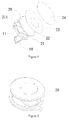
- the portable storage device comprises a chip shell or carrier 10 and an outer shell 20.Memory chips 11 are secured to the chip carrier 10.
- the outer shell 20 comprises a plastic body 21 to which the chip carrier 10 is connected, and a decorative layer consisting of a metal lid 22, a decorative sheet, for example paper, 23 and a transparent film 24.
- the decorative sheet 23 and the transparent film 24 in turn are crimped by means of a mould onto the metal lid 22 fastened on the plastic body 21.
- the plastic body 21 comprises a convex edge 211 or raised rim that bulges outward to be fastened with the metal lid 22.
- the patterns or colours on the decorative sheet 23 can be freely set so as to meet the uses' needs.
- the metal lid 22 is detached from the plastic body 21 to enable replacement of the original decorative sheet 23 with a new one, and then the transparent film 24 and the decorative sheet 23 are crimped on the metal lid 22 by the mould, which is convenient and simple.
- the overall dimensions of the decorative sheet 23 and the transparent film 24 are larger than those of the metal lid 22 so that they can wrap over the edges of the metal lid 22.
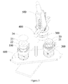
- the decorative layer can be formed by stamping equipment with a simple structure (see figure 3 ).
- the stamping equipment comprises a first lower die 100, a second lower die 200, an upper die 300, a die-set 400, a handle 500 and a lower die plate 600.
- the lower die plate 600 can rotate so that the first lower die 100 and the second lower die 200 are moved to the position corresponding to the upper die 300.
- the overall dimensions of the decorative sheet 23 and the transparent film 24 are basically the same as each other and larger than those of the metal lid 22, so that they can wrap over the edges of the metal lid 22.
- the dimension of the die cavity of the first lower die 100 is slightly larger than the overall dimensions of the decorative sheet 23 and the transparent film 24.
- the die core of the upper die 300 is provided with an inclined plane which presses the decorative sheet 23 and the transparent film 24 against the metal lid 22 when the upper die 300 presses downward.
- the base of the first lower die 100 is arranged with a spring, which causes the die sleeve of the first lower die 100 to float when the upper die 300 is contact with the first lower die 100, while the die core has relative movement so as to push against the inner cavity of the metal lid 22, thereby wrapping the inner surface of the metal lid 22 with the decorative sheet 23 and the transparent film 24 and obtaining the decorative layer.
- the plastic body 21, with its back side up is placed in the die cavity of the second lower die 200 and the decorative layer 20 is placed on the back side of the plastic body 21, then the lower die plate 600 is rotated so that the position of the second lower die 200 is corresponding with the upper die 300 and the handle 500 is pressed downwards so that the metal lid 22 wrapped with the decorative sheet 23 and the transparent film 24 undergoes inward deformations and is fastened on the convex edge 211 of the plastic body 21, thereby forming the outer shell 20.
- the metal lid 22 can be made of steel, aluminium alloy etc.
- the transparent film 23 is arranged outside of the decorative sheet 24 to completely wrap the surface of the metal lid 22.
- Such structure plays the role of preventing intrusion of water and dust and the users can randomly replace the colors or patterns so as to meet the different needs of users.
- the impact resistance of metal is comparatively higher than that of plastics materials. Therefore, due to the assembly of the metal lid 22 in the portable storage device of the invention, when it is subjected to external impacts, the metal lid 22 can better protect internal portable storage chips from being damaged so as to improve the impact resistance of the portable storage device and prolong the service life thereof.
- the memory chips 11 are fixed to the chip carrier 10, for example, by means of a double-faced adhesive tape. Other fixing techniques may be used.
- the memory chips 11 can be connected with the chip carrier 10 by gluing, in a very convenient manufacturing process.
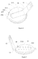
- the front side of the plastic body 21 is provided with an accommodating groove 212 conforming to the outline of the chip carrier 10.
- the length, width and depth of the accommodating groove 212 are basically the same as those of the chip carrier 10 so that the chip carrier 10 can be completely accommodated in the accommodating groove 212.
- the front end of the chip carrier 10 is pivotably connected to the body 21 at the front end of the accommodating groove 212 , while the side face of the back end of the accommodating groove 212 is arranged with an embossment 213 for retaining the chip carrier 10 within the accommodating groove 212.
- the embossment 213 can have the structure of bar-type or circular point type or a combination of bar-type and circular point type to retain the chip carrier 10.
- both sides of the chip carrier 10 are provided with depressions 12 corresponding to the embossment 213; the back side of the chip carrier 10 is flush with the end face of the outer shell 20 after it is clamped in the accommodating groove 212 by the embossment 213 and the depressions 12.
- the users can perceive whether the holding of the chip carrier 10 is in place, thereby improving the users' experience.
- the chip carrier 10 is held in the accommodating groove 212 of the outer shell 20 when the portable storage device of the implementation is not in use , and the chip carrier 10 is pivoted away from the plastic body 24 when the portable storage device is in use.
- the portable storage device of the implementation forms an integrated shape which can be carried as an ornament, thereby greatly improving the decoration of the portable storage device.
- the periphery of the above plastic body 21 is provided with a lug 215 extending outwards, provided with a punch-hole 216, extending in the direction corresponding to the depth of the accommodating groove 212.
- the punch-hole 216 can receive a cord or buckle, so the portable storage device of the invention can be carried by the users.
- the punch-hole 216 can receive a cord, through which the portable storage device of the invention can be carried by the users as an ornament; alternatively, the punch-hole 216 can receive a key ring so that the portable storage device of the invention can be carried as a key ring ornament.
- the back end of the accommodating groove 212 in the outer shell 20 may comprise a recess 214 that can be used to draw the chip carrier 10 from the groove by the user's finger.
- a recess 214 that can be used to draw the chip carrier 10 from the groove by the user's finger.
- the back end thereof is contact with that of the accommodating groove 212; however, if the gap between the chip carrier and the plastic body 21 is small because of the overall design, it can be inconvenient for the chip carrier 10 to be reversed about its pivot.
- the recess 214 at the back end of the accommodating groove 212, the user's fingers can reach the accommodating groove 212 to reverse the chip carrier 10.
- the front end of the accommodating groove 212 is provided with a cylindrical projection 2121
- the front end of the chip carrier 10 is provided with a hole 13 which receives the projection 2121 as a clearance fit so that the chip carrier 10 is pivoted with the outer shell 20.
- the chip carrier 10 is pivotably connected to the plastic body 21 by means of a hinge pin 30.
- the hinge pin 30 passes through a lateral passage 14 arranged on the front end of the chip carrier 10.
- Connecting holes 2122 are provided at the front end of the accommodating groove 212.
- the hinge pin 30 passes through the lateral passage 14 and is retained within the connecting holes 2122 so that the chip carrier 10 is pivoted with the outer shell 20.
- the outline of the above plastic body 21 can be selected according to the needs of the users.
- it can be circular as shown in the drawings, polygonal, elliptical or may have an irregular shape.
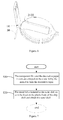
- the invention further provides a manufacturing method for the above portable storage device, as shown in fig. 7 , which includes the steps of:
- step S10 can specifically include:
- step S20 can specifically include:
- the die cavity of the second lower die 200 moves downwards and the edges of the metal lid 22 cover the convex edge 211; however, if the upper die 300 continues to be pressed downwards, the beveled edge of the second lower die 200 will cause the edges of the metal lid 22 to undergo inward flexural deformations so that the metal lid 22 is fastened with the convex edge 211, thereby obtaining the outer shell 20.
- the above method also includes the steps of gluing the memory chips to the chip carrier by a double-faced adhesive tape and pivotably connecting together the front ends of the chip carrier and the accommodating groove which is arranged on the front side of the plastic body and whose outline conforms to that of the chip carrier.
- the plastic body 21 can have a variety of shapes and structures. With reference to fig. 4 , in one embodiment of the invention, the plastic body 21 is provided with an accommodating groove 212 to accommodate the chip carrier. There are many connection methods between the memory chips 11 and the chip carrier 10, which are fixed by a glued joint in the described embodiment, which has the advantages of convenience, simplicity and low cost. After making the glued joint, the chip carrier 10 is pivotably connected to the accommodating groove 212, thereby basically accomplishing the manufacturing process of the storage device of the invention.
- the above step S21 can include: passing the hinge pin through the chip carrier and inserting it into the front end of the accommodating groove so that the chip carrier is pivoted with the accommodating groove; or butting a cylindrical projection that is arranged on the front end of the accommodating groove into a hole that is arranged on the front end of the chip carrier and has a clearance fit with the projection.
Landscapes
- Engineering & Computer Science (AREA)
- Microelectronics & Electronic Packaging (AREA)
- Packages (AREA)
- Toys (AREA)
Applications Claiming Priority (1)
| Application Number | Priority Date | Filing Date | Title |
|---|---|---|---|
| CN2010202789688U CN201838325U (zh) | 2010-08-02 | 2010-08-02 | 移动存储装置 |
Publications (1)
| Publication Number | Publication Date |
|---|---|
| EP2416636A2 true EP2416636A2 (de) | 2012-02-08 |
Family
ID=44008428
Family Applications (1)
| Application Number | Title | Priority Date | Filing Date |
|---|---|---|---|
| EP10192795A Withdrawn EP2416636A2 (de) | 2010-08-02 | 2010-11-26 | Tragbare Speichervorrichtung und Herstellungsverfahren dafür |
Country Status (2)
| Country | Link |
|---|---|
| EP (1) | EP2416636A2 (de) |
| CN (1) | CN201838325U (de) |
-
2010
- 2010-08-02 CN CN2010202789688U patent/CN201838325U/zh not_active Expired - Fee Related
- 2010-11-26 EP EP10192795A patent/EP2416636A2/de not_active Withdrawn
Non-Patent Citations (1)
| Title |
|---|
| None |
Also Published As
| Publication number | Publication date |
|---|---|
| CN201838325U (zh) | 2011-05-18 |
Similar Documents
| Publication | Publication Date | Title |
|---|---|---|
| US8081483B2 (en) | USB flash disk | |
| US7066089B1 (en) | Automatically re-inked stamp | |
| EP2416636A2 (de) | Tragbare Speichervorrichtung und Herstellungsverfahren dafür | |
| KR20130007175U (ko) | 모바일 단말기의 휴대용 고리 | |
| CN202206947U (zh) | 一种智能手机保护套 | |
| KR200462821Y1 (ko) | 캐릭터 형상의 휴대 전자기기 보호 케이스 | |
| CN109016481B (zh) | 一种手机膜贴膜方法 | |
| CN1090088C (zh) | 印模坯料、印模坯料安装支架及印模组件 | |
| JP2013150355A (ja) | 携帯電子機器 | |
| CN202004937U (zh) | 一种短款耳机座 | |
| JP3124111U (ja) | ソケット識別構造 | |
| CN202798826U (zh) | 一种手机套 | |
| CN215752080U (zh) | 一种卡夹可伸缩的杯托结构 | |
| CN210867822U (zh) | 一种手机单手架 | |
| CN213990739U (zh) | 一种嵌设皮质边条的手机保护套 | |
| US7216586B1 (en) | Portable stamp assembly | |
| KR100790166B1 (ko) | 도금 방법 | |
| JP3138760U (ja) | ゴムパッドの改良構造 | |
| CN210823444U (zh) | 一种环保的红酒包装结构 | |
| CN214205639U (zh) | 一种防摔的手机壳 | |
| CN209898440U (zh) | 一种具有耳机收纳功能的钥匙链 | |
| CN216033484U (zh) | 一种环境艺术用透写台 | |
| CN211684480U (zh) | 一种易撕型绘画本 | |
| CN216186940U (zh) | 一种瓶子 | |
| CN214317692U (zh) | 一种防尘便携记录饮水水杯 |
Legal Events
| Date | Code | Title | Description |
|---|---|---|---|
| AK | Designated contracting states |
Kind code of ref document: A2 Designated state(s): AL AT BE BG CH CY CZ DE DK EE ES FI FR GB GR HR HU IE IS IT LI LT LU LV MC MK MT NL NO PL PT RO RS SE SI SK SM TR |
|
| AX | Request for extension of the european patent |
Extension state: BA ME |
|
| PUAI | Public reference made under article 153(3) epc to a published international application that has entered the european phase |
Free format text: ORIGINAL CODE: 0009012 |
|
| RAP1 | Party data changed (applicant data changed or rights of an application transferred) |
Owner name: SHENZHEN XINJINGCAI TECHNOLOGY CO., LTD. |
|
| STAA | Information on the status of an ep patent application or granted ep patent |
Free format text: STATUS: THE APPLICATION HAS BEEN WITHDRAWN |
|
| 18W | Application withdrawn |
Effective date: 20150107 |