EP2416464A2 - Autonomes Modul zur Herstellung, Überwachung, Speicherung, Welligkeitssteuerung und Verteilung von Solarstrom, Verfahren zur Übermittlung und Steuerungsverwaltung zwischen Modulen bei Inselbetrieb - Google Patents
Autonomes Modul zur Herstellung, Überwachung, Speicherung, Welligkeitssteuerung und Verteilung von Solarstrom, Verfahren zur Übermittlung und Steuerungsverwaltung zwischen Modulen bei Inselbetrieb Download PDFInfo
- Publication number
- EP2416464A2 EP2416464A2 EP11005544A EP11005544A EP2416464A2 EP 2416464 A2 EP2416464 A2 EP 2416464A2 EP 11005544 A EP11005544 A EP 11005544A EP 11005544 A EP11005544 A EP 11005544A EP 2416464 A2 EP2416464 A2 EP 2416464A2
- Authority
- EP
- European Patent Office
- Prior art keywords
- mapef
- module
- grid
- master
- slave
- Prior art date
- Legal status (The legal status is an assumption and is not a legal conclusion. Google has not performed a legal analysis and makes no representation as to the accuracy of the status listed.)
- Withdrawn
Links
Images


Classifications
-
- H—ELECTRICITY
- H02—GENERATION; CONVERSION OR DISTRIBUTION OF ELECTRIC POWER
- H02J—CIRCUIT ARRANGEMENTS OR SYSTEMS FOR SUPPLYING OR DISTRIBUTING ELECTRIC POWER; SYSTEMS FOR STORING ELECTRIC ENERGY
- H02J3/00—Circuit arrangements for ac mains or ac distribution networks
- H02J3/28—Arrangements for balancing of the load in a network by storage of energy
- H02J3/32—Arrangements for balancing of the load in a network by storage of energy using batteries with converting means
-
- H—ELECTRICITY
- H02—GENERATION; CONVERSION OR DISTRIBUTION OF ELECTRIC POWER
- H02J—CIRCUIT ARRANGEMENTS OR SYSTEMS FOR SUPPLYING OR DISTRIBUTING ELECTRIC POWER; SYSTEMS FOR STORING ELECTRIC ENERGY
- H02J13/00—Circuit arrangements for providing remote indication of network conditions, e.g. an instantaneous record of the open or closed condition of each circuitbreaker in the network; Circuit arrangements for providing remote control of switching means in a power distribution network, e.g. switching in and out of current consumers by using a pulse code signal carried by the network
- H02J13/00004—Circuit arrangements for providing remote indication of network conditions, e.g. an instantaneous record of the open or closed condition of each circuitbreaker in the network; Circuit arrangements for providing remote control of switching means in a power distribution network, e.g. switching in and out of current consumers by using a pulse code signal carried by the network characterised by the power network being locally controlled
-
- H—ELECTRICITY
- H02—GENERATION; CONVERSION OR DISTRIBUTION OF ELECTRIC POWER
- H02J—CIRCUIT ARRANGEMENTS OR SYSTEMS FOR SUPPLYING OR DISTRIBUTING ELECTRIC POWER; SYSTEMS FOR STORING ELECTRIC ENERGY
- H02J3/00—Circuit arrangements for ac mains or ac distribution networks
- H02J3/38—Arrangements for parallely feeding a single network by two or more generators, converters or transformers
- H02J3/381—Dispersed generators
-
- H—ELECTRICITY
- H02—GENERATION; CONVERSION OR DISTRIBUTION OF ELECTRIC POWER
- H02J—CIRCUIT ARRANGEMENTS OR SYSTEMS FOR SUPPLYING OR DISTRIBUTING ELECTRIC POWER; SYSTEMS FOR STORING ELECTRIC ENERGY
- H02J3/00—Circuit arrangements for ac mains or ac distribution networks
- H02J3/38—Arrangements for parallely feeding a single network by two or more generators, converters or transformers
- H02J3/388—Islanding, i.e. disconnection of local power supply from the network
-
- H—ELECTRICITY
- H02—GENERATION; CONVERSION OR DISTRIBUTION OF ELECTRIC POWER
- H02J—CIRCUIT ARRANGEMENTS OR SYSTEMS FOR SUPPLYING OR DISTRIBUTING ELECTRIC POWER; SYSTEMS FOR STORING ELECTRIC ENERGY
- H02J7/00—Circuit arrangements for charging or depolarising batteries or for supplying loads from batteries
- H02J7/34—Parallel operation in networks using both storage and other dc sources, e.g. providing buffering
- H02J7/35—Parallel operation in networks using both storage and other dc sources, e.g. providing buffering with light sensitive cells
-
- H—ELECTRICITY
- H02—GENERATION; CONVERSION OR DISTRIBUTION OF ELECTRIC POWER
- H02J—CIRCUIT ARRANGEMENTS OR SYSTEMS FOR SUPPLYING OR DISTRIBUTING ELECTRIC POWER; SYSTEMS FOR STORING ELECTRIC ENERGY
- H02J2300/00—Systems for supplying or distributing electric power characterised by decentralized, dispersed, or local generation
- H02J2300/20—The dispersed energy generation being of renewable origin
- H02J2300/22—The renewable source being solar energy
- H02J2300/24—The renewable source being solar energy of photovoltaic origin
-
- H—ELECTRICITY
- H02—GENERATION; CONVERSION OR DISTRIBUTION OF ELECTRIC POWER
- H02J—CIRCUIT ARRANGEMENTS OR SYSTEMS FOR SUPPLYING OR DISTRIBUTING ELECTRIC POWER; SYSTEMS FOR STORING ELECTRIC ENERGY
- H02J2310/00—The network for supplying or distributing electric power characterised by its spatial reach or by the load
- H02J2310/10—The network having a local or delimited stationary reach
- H02J2310/12—The local stationary network supplying a household or a building
-
- Y—GENERAL TAGGING OF NEW TECHNOLOGICAL DEVELOPMENTS; GENERAL TAGGING OF CROSS-SECTIONAL TECHNOLOGIES SPANNING OVER SEVERAL SECTIONS OF THE IPC; TECHNICAL SUBJECTS COVERED BY FORMER USPC CROSS-REFERENCE ART COLLECTIONS [XRACs] AND DIGESTS
- Y02—TECHNOLOGIES OR APPLICATIONS FOR MITIGATION OR ADAPTATION AGAINST CLIMATE CHANGE
- Y02E—REDUCTION OF GREENHOUSE GAS [GHG] EMISSIONS, RELATED TO ENERGY GENERATION, TRANSMISSION OR DISTRIBUTION
- Y02E10/00—Energy generation through renewable energy sources
- Y02E10/50—Photovoltaic [PV] energy
- Y02E10/56—Power conversion systems, e.g. maximum power point trackers
-
- Y—GENERAL TAGGING OF NEW TECHNOLOGICAL DEVELOPMENTS; GENERAL TAGGING OF CROSS-SECTIONAL TECHNOLOGIES SPANNING OVER SEVERAL SECTIONS OF THE IPC; TECHNICAL SUBJECTS COVERED BY FORMER USPC CROSS-REFERENCE ART COLLECTIONS [XRACs] AND DIGESTS
- Y02—TECHNOLOGIES OR APPLICATIONS FOR MITIGATION OR ADAPTATION AGAINST CLIMATE CHANGE
- Y02E—REDUCTION OF GREENHOUSE GAS [GHG] EMISSIONS, RELATED TO ENERGY GENERATION, TRANSMISSION OR DISTRIBUTION
- Y02E40/00—Technologies for an efficient electrical power generation, transmission or distribution
- Y02E40/70—Smart grids as climate change mitigation technology in the energy generation sector
-
- Y—GENERAL TAGGING OF NEW TECHNOLOGICAL DEVELOPMENTS; GENERAL TAGGING OF CROSS-SECTIONAL TECHNOLOGIES SPANNING OVER SEVERAL SECTIONS OF THE IPC; TECHNICAL SUBJECTS COVERED BY FORMER USPC CROSS-REFERENCE ART COLLECTIONS [XRACs] AND DIGESTS
- Y02—TECHNOLOGIES OR APPLICATIONS FOR MITIGATION OR ADAPTATION AGAINST CLIMATE CHANGE
- Y02E—REDUCTION OF GREENHOUSE GAS [GHG] EMISSIONS, RELATED TO ENERGY GENERATION, TRANSMISSION OR DISTRIBUTION
- Y02E70/00—Other energy conversion or management systems reducing GHG emissions
- Y02E70/30—Systems combining energy storage with energy generation of non-fossil origin
Definitions
- the following invention consists of a photovoltaic electric power production module, its monitoring, storage, ripple, distribution and its method of communication control and management between modules as each module, being equipped with a communication system, can communicate with other modules belonging to the same grid.
- the aim of this invention is the production of photovoltaic energy, its monitoring, its storage, its ripple, its transformation and its distribution, to one or more households or other facilities, ensuring supply autonomy even in periods when production is not possible through this production method (at night or adverse weather conditions) in which each module which is equipped with a communication system where it can communicate with the others that are integrated in the same grid.
- This will report the system about the existing needs at every moment, making it possible to better manage the energy distribution depending on the storage capacity accumulated in the batteries of each module.
- the following invention aims at the implementation of the photovoltaic electric power production module (hereafter designated as MAPEF), its monitoring, its storage, its ripple, its distribution and its method of communication control and between modules, having a metallic supporting structure attached to the soil, on which the photovoltaic panels are to be installed, incorporating a technical cabinet in which is housed all the necessary equipment to monitor, store, ripple and raise the voltage and distribute electric power through individual or collective systems.
- MAPEF photovoltaic electric power production module
- Each MAPEF having the ability to communicate with other MAPEFs (1) on the same grid, allows the existence of an intelligent monitoring over the loads in the distribution grid. This way, all the receivers can be fed for the longest time possible, depending solely on individual consumption and the amount of energy stored in the batteries of each MAPEF.
- the WO 2008/124144 document refers to a modular system based on a principle of photovoltaic panels usage with incorporated inverters that allow their association in order to increase the power available in an installation. Additionally, this invention makes it possible the incorporation of storage batteries.
- a communication system to manage the input/output of the photovoltaic panels is indicated, regarding the grid impedance. To sum up, it consists of a photovoltaic panel, comprising the generating function of the panel, the DC-AC inverter, small storage batteries and a control circuit to turn on/off the photovoltaic panel, all included in the package.
- the module of this invention in which the photovoltaic panel is used for current commercialization, which does not incorporate any inverter or communications device.
- this system differs from the present invention because, among other things, it manages the available power on AC depending on the in/out working of the photovoltaic panels (DC). It is a system that is not designed for grid- integrated use.
- the module of the present invention performs the power management on the grid based on the available loads of the storage batteries of each module, allowing efficient management of the loads to be provided into the utility grid.
- each of these units has a voltage/current control of the distribution grid, as well as transformation to the voltages of normal use of the public distribution utilities, and protection on their outputs, unlike the WO 2008/124144 invention.
- the WO 2005/027300 document refers itself to an invention that optimizes and maximizes the security of the interconnection between solar panels and increases the efficiency of a set of interconnected photovoltaic panels. For that, it uses two power grids (a DC - direct current - and the other an AC - alternating current) in which the DC level of the grid is expected to increase the voltage in order to reduce the losses of energy.
- This invention unlike the present application, does not include the use of storage batteries, to provide power in a distribution grid.
- this invention takes into account that communication exists for the detection of photovoltaic panels malfunctions, as well as their in/out control command of the panels which transmits to the "master" inverter the results so that certain procedures can be adopted. Due to a greater or lesser number of PV panels connected to the grid, so there will be more or less energy in the AC grid. There is neither management of the stored loads nor the system is designed for grid operating, thus becoming adapted to installations that operate in isolation, which is not the scope of the invention of this patent application.
- Each MAPEF is characterized by being a production, storage and low voltage electric power distribution product (400 VAC, three- phase, 230 VAC or 110 VAC, single phase, 50Hz/60Hz frequency), from solar energy, with the ability to communicate with the other MAPEFs (1) existent on the same grid.
- 400 VAC three- phase, 230 VAC or 110 VAC, single phase, 50Hz/60Hz frequency
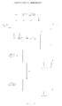
- Each MAPEF (1) shown in the operating scheme of Picture 6, consists of six distinct blocks, associated in a single metal structure: Generator (photovoltaic panels) (8), Load Regulator (DC/DC converter) (12), Storage Batteries (13), Inverter (Inverter DC/AC) (14), Transformer (29) and a Distribution Module made up by the inverter control (15), by the available communications (16), in case the MAPEFs (1) are installed in a grid system, by the Voltage/current control (17) and by the distribution grid (18).
- the generating function is performed by solar panels (8), arranged in suitable structure; the load regulator (12) ensures the correct loading of the storage batteries (13); the storage batteries (13) store the power produced by the generating element (8); the inverter (14) transforms the energy stored in the storage batteries (13) (continuous current) into electric power (alternate current), whose voltage will be increased by the transformer (29), to be used by daily use receptors(household appliances, lighting, etc..); the distribution (18)ensures that the power circuits in low voltage (alternating current), are properly protected to prevent accidents that could jeopardize the safety of people and equipment.
- the upper part of the MAPEF (1) is made up of a set of photovoltaic panels (8) arranged side by side (array) and connected in a way that the voltage that is generated at its terminals can be suitable for charging the storage batteries (13).
- This structure of photovoltaic panels (8) is sized to withstand the stresses resulting from the wind to an exposed surface up to 20 m 2 .
- the angle of inclination of the collectors (photovoltaic panels 8) which is a function of the geographic latitude of the installation, is set at installation time, through a system of rulers with the inclination marking of the angles.
- the system of base production and storage is designed for a 6 kWh power, constant throughout the year, so for this level of consumption it was decided to use batteries with a nominal rated capacity for a 48 V DC voltage; having in mind the following premises, the connection of photovoltaic panels should be such that in their terminals the voltage exceeds 48 V to allow recharging.
- the power may be modified by changing the capacity of the generator (photovoltaic panels), ensuring that the maximum voltage available is not less than 48 VDC.
- the manufacturers of photovoltaic panels indicate the amount of the produced current in the CTS reference conditions which seldom occur, thus for the overall calculation of the type of panels to be used the conditions of the nominal operating temperature of the cell module are taken into account.
- the global sizing of the number of photovoltaic panels to be installed in the structure will vary depending on the characteristics of the consumption to be achieved, taking into account the physical limitation of the 20 m 2 area. With this knowledge, you can get the number of panels depending on nominal power.
- photovoltaic panels (8) placed on the upper structure they are interconnected and connected to a 30 diodes bus whose function is to prevent photovoltaic panels (8) to behave as loads causing consumption of accumulated energy during night time and thus act as locking devices.
- the load regulator (12) is connected to this bus, whose function is to monitor and command the loading of the storage batteries (13) that will accumulate the energy produced by photovoltaic panels (8).
- photovoltaic panels (8), load regulators (12), storage batteries (13) and inverters (14), may be changed depending on the loads that are intended to be fed, the intended autonomy and the characteristics of the distribution grid.
- the number of transformers (29) may vary between one and three, depending on the MAPEF (1), if it is prepared to feed a single phase or three-phase loads.
- This modular system allows each MAPEF (1) to work in an individual way, not sharing loads that are not fed directly by itself (directly loads are all those that are protected by the distribution system itself, integrated into the equipment) or in the grid, sharing loads that are not fed directly by itself.
- Microcontroller 3 performs the function of the internal management of the module, as among other tasks, it keeps the grid inner status table updated based on the information received from the grid through microcontroller 1.
- Microcontroller 2 shall be responsible for acquiring signals from the grid and the module itself, and command the inverter.
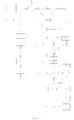
- the control inverter (15) consists of three operating stages: the Power Stage, the Command Stage and the Communication Stage.
- the Power Stage is developed by a structure based on full bridge of IGBT transistors, led by two independent" drivers" for IGBTs with neither additional control circuits nor in dead time.
- a microcontroller is used to command two independent "drivers" for IGBTs.
- the control will be the result of voltage and current measurements that will be taken out of each MAPEF (1), as well as on the distribution grid (18).
- the voltage and current measurements will be taken by AC 27 transistors, whose resulting greatness will be converted by a A/D (analog-to-digital) converter in order to be interpreted by the microcontroller.
- the control of the inverter (15) will be controlled through the "drivers" associated with each IGBT transistor.
- the predicted communication system is a system based on microcontrollers.
- the control of the inverter (15) has got a microcontroller dedicated to control itself, and the system that performs the interface between the inverter control (15).
- the grid will also be ensured by another microcontroller with different characteristics from the one used to control the inverter (15).
- This series communication is internal within the same MAPEF (1), and can be applied to isolated operation and grid connected.
- MAPEFs (1) In addition, and valid only for the grid connected, in the communication between MAPEFs (1) (outdoor) it is used the CANbus system (26) (ECAN protocol) for transmission times up to 4 ⁇ s (250 kbps), allowing distances between MAPEFs (1) up to 250 m. It uses a high traffic system (high number of messages sent and received on MAPEFs (1)), with a high amount of information.
- CANbus system 266
- Each MAPEF (1) has got two communication systems: a serial-type system that uses the UART system of communication of microcontrollers, which allows the "dialogue” between the microcontroller that integrates the control command of the inverter (15) ( ⁇ C2) and a second microcontroller integrating the communications interface ( ⁇ C1); a CANbus communication system (26) between different MAPEFs (1), in which a microcontroller is used which integrates the communication interface.
- the aim of the first communication system is to allow communication of the values of voltages and currents in the DC bus (voltage/current battery supply) and AC (voltage/current inverter output) in order to maintain an updated table in the last one and receive in the microcontroller that integrates the inverter control (14) the start and stop commands that are generated in the microcontroller of the communication interface.
- the microcontroller that integrates the inverter control (14) sends 4 bytes (each one referring to a magnitude of a total of 256 possible values) and receives one byte (start, stop commands, or null).
- the transmission speed serial is 19,200 bps.
- the communication strategy follows the following methodology:
- the basic principle for assigning the "master” function is given by the identifier that the operator sets up in an initial grid configuration.
- the identifier or ID is a word with 5 bits, resulting from the value "read” by ⁇ C3 of a switch that is set. Each ID must be unique, and the lowest ID grid will allow the module to be assigned as "master”.
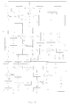
- the qualification/disqualification of modules from "master” to “slave” and vice versa is a constant in the grid when operating according to the following criteria and to the management of the process as in Pictures 19, 20 and 21.
- the MAPEF "master" constantly inquires the grid in order to find out which of the MAPEFs (1) are active, and in what status; then a choice is made from the MAPEFs (1) which should start working by selecting those that have the best performance, and likewise, which have to stop working due to their poor performance. This selection is related to the available stored loads, no malfunctions, etc..; simultaneously, through the current transducers that are installed in the grid the amount of the load is evaluated, so as to choose among the best, which are likely to start working, and likewise, which ones among the worst should stop working. These tasks are carried out in a dynamic way; to implement this system in a decentralized way by creating a common table, which is transmitted to all MAPEFs (1). The status of the grid kept in the common table, is stored in EEPROM (Electrically Erasable Programmable Read-Only Memory) and exists in each MAPEF (1), being one of the communications devices (16).
- EEPROM Electrical Erasable Programmable Read-Only Memory
- the structure of the information stored in the EEPROM is identified in Picture 20.
- the first two bits are kept aside for the identification of the type of module ("master” or "slave"), the next five bits keep the value of the module identification, the serial number of that module is stored in the next byte, the next 5 bit keep the operating time of the module updated; the next three bits are responsible for keeping the load level of the main batteries; the next two bits identify the condition of the grid module (ON, OFF, IDLE or UNKNOW); the last bits are also kept aside so that the "master" module can always keep all the modules under surveillance.
- This table keeps record of the condition of the grid and of all MAPEFs (1) and is managed by the "master" module. As there is a certain time of transmission between MAPEFs (1), there will be a predicted minimum time between starting and stopping the inverters (15) in order to avoid transient anomalies. This stage of communication is also controlled by a microcontroller, using the CANbus protocol (26). With this system, each inverter control (15) of each MAPEF (1) is interconnected between themselves through a conductor cable with termination resistors as shown in Picture 14. The communication door will be of a RS232 type which will allow the interconnection of the MAPEFs (1) communications. The regulation of the electrical power available in the distribution grid will result from measures taken in the stage command and its transmission to the grid connected MAPEFs (1). When operating individually, there is no communication with the CANbus protocol (26).
- the output power into the distribution network and the automatic entry into operation of MAPEFs (1) will depend on the specific needs of power in the grid, resulting from the existing consumption and the load availability stored in the storage batteries (13) of the MAPEF (1) so that it can contribute with power. Once these conditions are met, the module will start working, will carry out self synchronization to enter the grid. This synchronization is performed by sending a clock signal in real time - RTC, so the whole grid can operate under the same voltage and frequency standards.
- each MAPEF (1) has an autonomous supply system through the backup battery which will be kept at the nominal load, thanks to the implementation of a DC/DC battery charger to charge the backup storage battery (13) (12V/7Ah). All the auxiliary systems are kept working in priority with the load available in the main storage batteries (13); the backup battery only starts working when they are empty. This management is ensured by microcontroller 3, associated to an alphanumeric device (LCD) to enable communication between the operator and the system.
- the global settings of the MAPEF (1) are stored in the EEPROM of microcontroller 3. Only skilled operators can make a MAPEF (1) work, that is why each MAPEF (1) has a numeric keypad to enter the access code in order to activate its operation.
- the MAPEF is taken out of service, being this information transmitted to the user through an alphanumeric LCD display.
- an "ENABLE" signal is sent to microcontroller 1, starting the communication cycle, between both "master” MAPEF (1) and the “slave” MAPEFs (1), by using the communications made through CANbus protocol (26). These communications are made through 6 bytes messages in which the first 2 bytes identify the ID of the MAPEF (1) and the remaining 4 bytes the message itself.
- the first communication step is to check if the module is the only module in the grid or if there are already others. In this situation, a message with the "PING MASTER” ID will let you know if there is already a "master" module in the grid.
- the new module that searches for its grid authentication, requests a message to the existent "master" module in relation to its ID.
- the module with the lowest ID will take over the role of "master” even if the existent module will be or will no longer be the "master".
- the MAPEF (1) "master” will send a message destination with the MAPEF ID identification, a message without specific contents, with the aim of obtaining data on the state of all "slave" MAPEFs (1).
- each MAPEF (1) gets a message, it interrupts the ongoing process by sending the MAPEF (1) "master” a message with its current state, and ignores the previous message for not having contents for processing.
- the state table is managed by the "master" module in charge. It is updated on a regular basis and reflects the condition of all the modules of the grid.
- the "master” module will always take over this function as long as it has the capacity to maintain grid communications in continuous operation. This function will only be ensured if there is power in its backup battery; if that fails to happen, the "master” module will be disqualified, and the "slave” module with the lowest ID will be promoted to "master” as long as there is nothing that prevents it from happening.
- each "slave" MAPEF (1) When each "slave” MAPEF (1) receives the message from the MAPEF "master”, it checks if the message is addressed to itself, ignoring it if it is not the case; if the message is addressed to it, it interrupts the ongoing process, and through the UART communication of microcontroller 1 to microcontroller 2, it executes the command received from the "master” MAPEF (1) by sending the "master” MAPEF (1) the current operation state, indicating the (on/off) state of the inverter (14) and the batteries load level.
- This information will be transmitted to the CANbus network so it can be interpreted by other MAPEFs (1).
- the MAPEF (1) "master”, which has got the updated state of the grid will send a synchronism signal to the grid (through a signal in real time clock - RTC), and a command to a certain MAPEF (1) that offers operating conditions. The reverse process will occur if it is necessary to reduce the grid power distribution.
- microcontroller 3 reads the voltage of the storage batteries (13), converting that value into an equivalent proportional signal to be interpreted by microcontroller 1. If the value of the reading is below the reference value, a message is sent to the LCD alphanumeric display with this information, and the routine is finished.
- microcontroller 3 will then read the voltage of the backup battery. If the value of the reading is below the reference value, a message is sent to the LCD alphanumeric display with this information, and the routine is finished.
- a message is sent to the LCD alphanumeric display with this information and the routine is finished. If the temperature sensor is present, it is checked if the temperature is below the predetermined temperature. If this temperature exceeds the predetermined reference temperature, forced ventilation is driven by a PWM speed control, allowing the temperature to fall down either in the IGBT power transistors or in the control system of the backup battery.
- the dynamics of the communication between modules is always centred in the "master" module according to the principles already set out, taking into account the respective ID, the current state, the state of the batteries loads and the Presence State.
- Microcontroller 2 reads the DC current/voltage in the MAPEF (1) module and through UART communication sends this information to microcontroller 1. If the current increases more than a predetermined value, microcontroller 1 gives instructions to microcontroller 2, through UART communication, to turn off the inverter.
- Microcontroller 1 gives instructions to microcontroller 2 to turn off the inverter by using UART communication.
Landscapes
- Engineering & Computer Science (AREA)
- Power Engineering (AREA)
- Charge And Discharge Circuits For Batteries Or The Like (AREA)
- Cable Transmission Systems, Equalization Of Radio And Reduction Of Echo (AREA)
- Supply And Distribution Of Alternating Current (AREA)
Applications Claiming Priority (1)
| Application Number | Priority Date | Filing Date | Title |
|---|---|---|---|
| PT105189A PT105189B (pt) | 2010-07-07 | 2010-07-07 | Módulo autónomo de produção, regulação, armazenamento, ondulação e distribuição de energia eléctrica fotovoltaica e método de controlo e gestão das comunicações entre módulos quando inseridos numa rede |
Publications (2)
| Publication Number | Publication Date |
|---|---|
| EP2416464A2 true EP2416464A2 (de) | 2012-02-08 |
| EP2416464A3 EP2416464A3 (de) | 2014-06-04 |
Family
ID=45350380
Family Applications (1)
| Application Number | Title | Priority Date | Filing Date |
|---|---|---|---|
| EP11005544.9A Withdrawn EP2416464A3 (de) | 2010-07-07 | 2011-07-07 | Autonomes Modul zur Herstellung, Überwachung, Speicherung, Welligkeitssteuerung und Verteilung von Solarstrom, Verfahren zur Übermittlung und Steuerungsverwaltung zwischen Modulen bei Inselbetrieb |
Country Status (2)
| Country | Link |
|---|---|
| EP (1) | EP2416464A3 (de) |
| PT (1) | PT105189B (de) |
Cited By (26)
| Publication number | Priority date | Publication date | Assignee | Title |
|---|---|---|---|---|
| WO2015083103A1 (en) * | 2013-12-04 | 2015-06-11 | Drives And Motors D.O.O. | System for generating and delivering electric energy derived preferably from renewable sources |
| WO2015144194A1 (en) * | 2014-03-24 | 2015-10-01 | Abb Technology Ltd | Control of energy storages in a microgrid |
| US9312522B2 (en) | 2012-10-18 | 2016-04-12 | Ambri Inc. | Electrochemical energy storage devices |
| US9502737B2 (en) | 2013-05-23 | 2016-11-22 | Ambri Inc. | Voltage-enhanced energy storage devices |
| US9520618B2 (en) | 2013-02-12 | 2016-12-13 | Ambri Inc. | Electrochemical energy storage devices |
| FR3043274A1 (fr) * | 2015-11-03 | 2017-05-05 | Upowa | Dispositif electrique autonome a controle differe |
| EP3190681A1 (de) * | 2016-01-07 | 2017-07-12 | Commissariat À L'Énergie Atomique Et Aux Énergies Alternatives | Verfahren und vorrichtung zum aufladen einer batterie |
| US9735450B2 (en) | 2012-10-18 | 2017-08-15 | Ambri Inc. | Electrochemical energy storage devices |
| US9893385B1 (en) | 2015-04-23 | 2018-02-13 | Ambri Inc. | Battery management systems for energy storage devices |
| CN108879761A (zh) * | 2018-06-23 | 2018-11-23 | 安徽富煌电控设备有限公司 | 一种敏感自复式光伏并网柜 |
| US10181800B1 (en) | 2015-03-02 | 2019-01-15 | Ambri Inc. | Power conversion systems for energy storage devices |
| US10270139B1 (en) | 2013-03-14 | 2019-04-23 | Ambri Inc. | Systems and methods for recycling electrochemical energy storage devices |
| US10541451B2 (en) | 2012-10-18 | 2020-01-21 | Ambri Inc. | Electrochemical energy storage devices |
| US10608212B2 (en) | 2012-10-16 | 2020-03-31 | Ambri Inc. | Electrochemical energy storage devices and housings |
| US10637015B2 (en) | 2015-03-05 | 2020-04-28 | Ambri Inc. | Ceramic materials and seals for high temperature reactive material devices |
| US11211641B2 (en) | 2012-10-18 | 2021-12-28 | Ambri Inc. | Electrochemical energy storage devices |
| US11387497B2 (en) | 2012-10-18 | 2022-07-12 | Ambri Inc. | Electrochemical energy storage devices |
| US11411254B2 (en) | 2017-04-07 | 2022-08-09 | Ambri Inc. | Molten salt battery with solid metal cathode |
| WO2022184809A1 (en) * | 2021-03-03 | 2022-09-09 | Sympower B.V. | A power balancing reserve for an electrical grid |
| CN116404698A (zh) * | 2023-06-02 | 2023-07-07 | 国网信息通信产业集团有限公司 | 一种基于扰动观察法的光伏能量路由控制方法及系统 |
| US11721841B2 (en) | 2012-10-18 | 2023-08-08 | Ambri Inc. | Electrochemical energy storage devices |
| CN117293828A (zh) * | 2023-11-27 | 2023-12-26 | 汉信数字(山西)智能信息科技有限公司 | 一种能源管控系统 |
| US11899438B1 (en) | 2022-12-15 | 2024-02-13 | Halliburton Energy Services, Inc. | Distributed control system with failover capabilities for physical well equipment |
| US11899410B1 (en) | 2022-12-15 | 2024-02-13 | Halliburton Energy Services, Inc. | Monitoring a wellbore operation using distributed artificial intelligence |
| US11909004B2 (en) | 2013-10-16 | 2024-02-20 | Ambri Inc. | Electrochemical energy storage devices |
| US11929466B2 (en) | 2016-09-07 | 2024-03-12 | Ambri Inc. | Electrochemical energy storage devices |
Families Citing this family (2)
| Publication number | Priority date | Publication date | Assignee | Title |
|---|---|---|---|---|
| DE102018205492A1 (de) * | 2018-04-11 | 2019-10-17 | Trumpf Werkzeugmaschinen Gmbh + Co. Kg | Zwischenmodul, Empfängermodul, Überwachungssystem und Überwachungsverfahren |
| EP3561980B1 (de) * | 2018-04-25 | 2023-06-14 | Schneider Electric Industries SAS | Mikronetz-überstromschutzvorrichtung |
Citations (3)
| Publication number | Priority date | Publication date | Assignee | Title |
|---|---|---|---|---|
| US6311137B1 (en) | 1999-01-27 | 2001-10-30 | Canon Kabushiki Kaisha | Information display apparatus, information relay apparatus used in power generation system, information display method and information relay method, and information transmission method |
| WO2005027300A1 (en) | 2003-09-16 | 2005-03-24 | Solarit Ab | A module, a converter, a node, and a system |
| WO2008124144A1 (en) | 2007-04-06 | 2008-10-16 | Sunovia Energy Technologies, Inc. | Modular ac solar panel system |
Family Cites Families (2)
| Publication number | Priority date | Publication date | Assignee | Title |
|---|---|---|---|---|
| US20060158037A1 (en) * | 2005-01-18 | 2006-07-20 | Danley Douglas R | Fully integrated power storage and supply appliance with power uploading capability |
| DE102007022879A1 (de) * | 2007-05-14 | 2008-11-27 | Sma Solar Technology Ag | Wechselrichter zur Netzeinspeisung in ein Wechselstromnetz |
-
2010
- 2010-07-07 PT PT105189A patent/PT105189B/pt active IP Right Grant
-
2011
- 2011-07-07 EP EP11005544.9A patent/EP2416464A3/de not_active Withdrawn
Patent Citations (3)
| Publication number | Priority date | Publication date | Assignee | Title |
|---|---|---|---|---|
| US6311137B1 (en) | 1999-01-27 | 2001-10-30 | Canon Kabushiki Kaisha | Information display apparatus, information relay apparatus used in power generation system, information display method and information relay method, and information transmission method |
| WO2005027300A1 (en) | 2003-09-16 | 2005-03-24 | Solarit Ab | A module, a converter, a node, and a system |
| WO2008124144A1 (en) | 2007-04-06 | 2008-10-16 | Sunovia Energy Technologies, Inc. | Modular ac solar panel system |
Cited By (42)
| Publication number | Priority date | Publication date | Assignee | Title |
|---|---|---|---|---|
| US10608212B2 (en) | 2012-10-16 | 2020-03-31 | Ambri Inc. | Electrochemical energy storage devices and housings |
| US10541451B2 (en) | 2012-10-18 | 2020-01-21 | Ambri Inc. | Electrochemical energy storage devices |
| US11611112B2 (en) | 2012-10-18 | 2023-03-21 | Ambri Inc. | Electrochemical energy storage devices |
| US11721841B2 (en) | 2012-10-18 | 2023-08-08 | Ambri Inc. | Electrochemical energy storage devices |
| US9825265B2 (en) | 2012-10-18 | 2017-11-21 | Ambri Inc. | Electrochemical energy storage devices |
| US11387497B2 (en) | 2012-10-18 | 2022-07-12 | Ambri Inc. | Electrochemical energy storage devices |
| US11211641B2 (en) | 2012-10-18 | 2021-12-28 | Ambri Inc. | Electrochemical energy storage devices |
| US11196091B2 (en) | 2012-10-18 | 2021-12-07 | Ambri Inc. | Electrochemical energy storage devices |
| US9735450B2 (en) | 2012-10-18 | 2017-08-15 | Ambri Inc. | Electrochemical energy storage devices |
| US9312522B2 (en) | 2012-10-18 | 2016-04-12 | Ambri Inc. | Electrochemical energy storage devices |
| US9728814B2 (en) | 2013-02-12 | 2017-08-08 | Ambri Inc. | Electrochemical energy storage devices |
| US9520618B2 (en) | 2013-02-12 | 2016-12-13 | Ambri Inc. | Electrochemical energy storage devices |
| US10270139B1 (en) | 2013-03-14 | 2019-04-23 | Ambri Inc. | Systems and methods for recycling electrochemical energy storage devices |
| US10297870B2 (en) | 2013-05-23 | 2019-05-21 | Ambri Inc. | Voltage-enhanced energy storage devices |
| US9559386B2 (en) | 2013-05-23 | 2017-01-31 | Ambri Inc. | Voltage-enhanced energy storage devices |
| US9502737B2 (en) | 2013-05-23 | 2016-11-22 | Ambri Inc. | Voltage-enhanced energy storage devices |
| US11909004B2 (en) | 2013-10-16 | 2024-02-20 | Ambri Inc. | Electrochemical energy storage devices |
| WO2015083103A1 (en) * | 2013-12-04 | 2015-06-11 | Drives And Motors D.O.O. | System for generating and delivering electric energy derived preferably from renewable sources |
| WO2015144194A1 (en) * | 2014-03-24 | 2015-10-01 | Abb Technology Ltd | Control of energy storages in a microgrid |
| CN106463965B (zh) * | 2014-03-24 | 2019-06-07 | Abb瑞士股份有限公司 | 微网中的能量存储的分散控制方法和相关联的设备 |
| US9762066B2 (en) | 2014-03-24 | 2017-09-12 | Abb Schweiz Ag | Control of energy storages in a microgrid |
| CN106463965A (zh) * | 2014-03-24 | 2017-02-22 | Abb瑞士股份有限公司 | 微网中的能量存储的控制 |
| US10181800B1 (en) | 2015-03-02 | 2019-01-15 | Ambri Inc. | Power conversion systems for energy storage devices |
| US10566662B1 (en) | 2015-03-02 | 2020-02-18 | Ambri Inc. | Power conversion systems for energy storage devices |
| US10637015B2 (en) | 2015-03-05 | 2020-04-28 | Ambri Inc. | Ceramic materials and seals for high temperature reactive material devices |
| US11289759B2 (en) | 2015-03-05 | 2022-03-29 | Ambri, Inc. | Ceramic materials and seals for high temperature reactive material devices |
| US11840487B2 (en) | 2015-03-05 | 2023-12-12 | Ambri, Inc. | Ceramic materials and seals for high temperature reactive material devices |
| US9893385B1 (en) | 2015-04-23 | 2018-02-13 | Ambri Inc. | Battery management systems for energy storage devices |
| WO2017076552A1 (fr) * | 2015-11-03 | 2017-05-11 | Upowa | Dispositif electrique autonome a controle differe |
| FR3043274A1 (fr) * | 2015-11-03 | 2017-05-05 | Upowa | Dispositif electrique autonome a controle differe |
| FR3046706A1 (fr) * | 2016-01-07 | 2017-07-14 | Commissariat Energie Atomique | Procede et dispositif de charge d'une batterie |
| EP3190681A1 (de) * | 2016-01-07 | 2017-07-12 | Commissariat À L'Énergie Atomique Et Aux Énergies Alternatives | Verfahren und vorrichtung zum aufladen einer batterie |
| US11929466B2 (en) | 2016-09-07 | 2024-03-12 | Ambri Inc. | Electrochemical energy storage devices |
| US11411254B2 (en) | 2017-04-07 | 2022-08-09 | Ambri Inc. | Molten salt battery with solid metal cathode |
| CN108879761A (zh) * | 2018-06-23 | 2018-11-23 | 安徽富煌电控设备有限公司 | 一种敏感自复式光伏并网柜 |
| WO2022184809A1 (en) * | 2021-03-03 | 2022-09-09 | Sympower B.V. | A power balancing reserve for an electrical grid |
| US11899438B1 (en) | 2022-12-15 | 2024-02-13 | Halliburton Energy Services, Inc. | Distributed control system with failover capabilities for physical well equipment |
| US11899410B1 (en) | 2022-12-15 | 2024-02-13 | Halliburton Energy Services, Inc. | Monitoring a wellbore operation using distributed artificial intelligence |
| CN116404698A (zh) * | 2023-06-02 | 2023-07-07 | 国网信息通信产业集团有限公司 | 一种基于扰动观察法的光伏能量路由控制方法及系统 |
| CN116404698B (zh) * | 2023-06-02 | 2023-10-17 | 国网信息通信产业集团有限公司 | 一种基于扰动观察法的光伏能量路由控制方法及系统 |
| CN117293828A (zh) * | 2023-11-27 | 2023-12-26 | 汉信数字(山西)智能信息科技有限公司 | 一种能源管控系统 |
| CN117293828B (zh) * | 2023-11-27 | 2024-02-02 | 汉信数字(山西)智能信息科技有限公司 | 一种能源管控系统 |
Also Published As
| Publication number | Publication date |
|---|---|
| PT105189A (pt) | 2012-01-09 |
| EP2416464A3 (de) | 2014-06-04 |
| PT105189B (pt) | 2014-12-12 |
Similar Documents
| Publication | Publication Date | Title |
|---|---|---|
| EP2416464A2 (de) | Autonomes Modul zur Herstellung, Überwachung, Speicherung, Welligkeitssteuerung und Verteilung von Solarstrom, Verfahren zur Übermittlung und Steuerungsverwaltung zwischen Modulen bei Inselbetrieb | |
| CN108075324B (zh) | 智能插座 | |
| US10263430B2 (en) | Multi-phase inverter power control systems in an energy generation system | |
| US8970176B2 (en) | DC micro-grid | |
| US10873099B1 (en) | Storage system controller | |
| KR101539572B1 (ko) | 외부 전력 계통 연계형 태양광, ess 및 전기차 충전 융복합 증강현실 시스템 | |
| US11264807B2 (en) | Renewable energy metering system | |
| US10530157B2 (en) | Commanding distributed energy resources | |
| US20110004357A1 (en) | System and method for single plug-in installation of a high voltage intelligent renewable energy grid-tied controller with wireless smart load management | |
| KR101545060B1 (ko) | Ess 분산제어 기반의 스마트그리드 통합 전력제어시스템 | |
| CN103872784A (zh) | 储能电源柜及具有其的并网供电系统及离网供电系统 | |
| US11428710B2 (en) | Methods and systems for connecting and metering distributed energy resource devices | |
| US20200366101A1 (en) | Energy storage system | |
| CN103733474A (zh) | 用于生成、存储和供应由模块化dc生成器产生的电能的系统以及用于管理所述系统的相关方法 | |
| CN104981955A (zh) | 自形成微电网 | |
| Karandeh et al. | Placement evaluation of distributed energy storage for integrating ev charging and pv solar infrastructure | |
| CN107743671B (zh) | 消费者的存储单元、存储系统和控制存储系统的方法 | |
| CN115191068A (zh) | 配置成与能量管理系统一起使用的存储系统 | |
| JP2020068555A (ja) | 電力管理システム及び集合住宅 | |
| JP7098867B2 (ja) | 電力システムおよび処理装置 | |
| Clarke et al. | Development of Demand and Supply Management Control Systems for Network Connected Photovoltaic Systems | |
| AU2016100112A4 (en) | Solar Power System | |
| AU2015230704A1 (en) | Solar Power System | |
| ELECTRIFICATION | POWER CONDITIONING |
Legal Events
| Date | Code | Title | Description |
|---|---|---|---|
| AK | Designated contracting states |
Kind code of ref document: A2 Designated state(s): AL AT BE BG CH CY CZ DE DK EE ES FI FR GB GR HR HU IE IS IT LI LT LU LV MC MK MT NL NO PL PT RO RS SE SI SK SM TR |
|
| AX | Request for extension of the european patent |
Extension state: BA ME |
|
| PUAI | Public reference made under article 153(3) epc to a published international application that has entered the european phase |
Free format text: ORIGINAL CODE: 0009012 |
|
| 17P | Request for examination filed |
Effective date: 20120705 |
|
| R17P | Request for examination filed (corrected) |
Effective date: 20120704 |
|
| R17P | Request for examination filed (corrected) |
Effective date: 20120705 |
|
| PUAL | Search report despatched |
Free format text: ORIGINAL CODE: 0009013 |
|
| AK | Designated contracting states |
Kind code of ref document: A3 Designated state(s): AL AT BE BG CH CY CZ DE DK EE ES FI FR GB GR HR HU IE IS IT LI LT LU LV MC MK MT NL NO PL PT RO RS SE SI SK SM TR |
|
| AX | Request for extension of the european patent |
Extension state: BA ME |
|
| RIC1 | Information provided on ipc code assigned before grant |
Ipc: H02J 13/00 20060101ALI20140429BHEP Ipc: H02J 3/38 20060101AFI20140429BHEP Ipc: H02J 3/32 20060101ALI20140429BHEP Ipc: H02J 7/35 20060101ALI20140429BHEP |
|
| 17Q | First examination report despatched |
Effective date: 20181005 |
|
| STAA | Information on the status of an ep patent application or granted ep patent |
Free format text: STATUS: THE APPLICATION IS DEEMED TO BE WITHDRAWN |
|
| 18D | Application deemed to be withdrawn |
Effective date: 20200709 |