EP2416205A1 - Plaque Lummer-Gehrcke commutable - Google Patents
Plaque Lummer-Gehrcke commutable Download PDFInfo
- Publication number
- EP2416205A1 EP2416205A1 EP10171872A EP10171872A EP2416205A1 EP 2416205 A1 EP2416205 A1 EP 2416205A1 EP 10171872 A EP10171872 A EP 10171872A EP 10171872 A EP10171872 A EP 10171872A EP 2416205 A1 EP2416205 A1 EP 2416205A1
- Authority
- EP
- European Patent Office
- Prior art keywords
- lummer
- gehrcke
- plate
- light
- electrodes
- Prior art date
- Legal status (The legal status is an assumption and is not a legal conclusion. Google has not performed a legal analysis and makes no representation as to the accuracy of the status listed.)
- Withdrawn
Links
Images

Classifications
-
- G—PHYSICS
- G02—OPTICS
- G02F—OPTICAL DEVICES OR ARRANGEMENTS FOR THE CONTROL OF LIGHT BY MODIFICATION OF THE OPTICAL PROPERTIES OF THE MEDIA OF THE ELEMENTS INVOLVED THEREIN; NON-LINEAR OPTICS; FREQUENCY-CHANGING OF LIGHT; OPTICAL LOGIC ELEMENTS; OPTICAL ANALOGUE/DIGITAL CONVERTERS
- G02F1/00—Devices or arrangements for the control of the intensity, colour, phase, polarisation or direction of light arriving from an independent light source, e.g. switching, gating or modulating; Non-linear optics
- G02F1/01—Devices or arrangements for the control of the intensity, colour, phase, polarisation or direction of light arriving from an independent light source, e.g. switching, gating or modulating; Non-linear optics for the control of the intensity, phase, polarisation or colour
- G02F1/0128—Devices or arrangements for the control of the intensity, colour, phase, polarisation or direction of light arriving from an independent light source, e.g. switching, gating or modulating; Non-linear optics for the control of the intensity, phase, polarisation or colour based on electro-mechanical, magneto-mechanical, elasto-optic effects
- G02F1/0131—Devices or arrangements for the control of the intensity, colour, phase, polarisation or direction of light arriving from an independent light source, e.g. switching, gating or modulating; Non-linear optics for the control of the intensity, phase, polarisation or colour based on electro-mechanical, magneto-mechanical, elasto-optic effects based on photo-elastic effects, e.g. mechanically induced birefringence
- G02F1/0134—Devices or arrangements for the control of the intensity, colour, phase, polarisation or direction of light arriving from an independent light source, e.g. switching, gating or modulating; Non-linear optics for the control of the intensity, phase, polarisation or colour based on electro-mechanical, magneto-mechanical, elasto-optic effects based on photo-elastic effects, e.g. mechanically induced birefringence in optical waveguides
-
- G—PHYSICS
- G02—OPTICS
- G02F—OPTICAL DEVICES OR ARRANGEMENTS FOR THE CONTROL OF LIGHT BY MODIFICATION OF THE OPTICAL PROPERTIES OF THE MEDIA OF THE ELEMENTS INVOLVED THEREIN; NON-LINEAR OPTICS; FREQUENCY-CHANGING OF LIGHT; OPTICAL LOGIC ELEMENTS; OPTICAL ANALOGUE/DIGITAL CONVERTERS
- G02F2202/00—Materials and properties
- G02F2202/42—Materials having a particular dielectric constant
Definitions
- the present invention relates to a switchable Lummer-Gehrcke plate. It further relates to an interferometer which comprises a switchable Lummer-Gehrcke plate according to the invention, a method for operating such an interferometer and the use of a Lummer-Gehrcke plate according to the invention.
- Interferometers are devices for the determination of interferences for the precision measurement of lengths, refractive indices, angles and for use in spectroscopy.
- the type and location of the interference patterns provide information about the interference or the factors causing the interference.
- Lummer-Gehrcke interferometer One type of interferometer is a Lummer-Gehrcke interferometer.
- the Lummer Gehrcke interferometer comprises a plane-parallel plate, the so-called Lummer Gehrcke plate. This has a refractive index of greater than 1 and has in longitudinal section the shape of a slender rectangle, which is illuminated at one end with a coherent light beam.
- the light beam is partially reflected and partially refracted upon entering the plate at the plate surface.
- the broken part of the light beam penetrates the plate and reaches the other surface of the plate, where it is also partly reflected back into the plate interior and refracted upon exiting the plate.
- the reflected light beam on the surface inside the plate passes through the plate and is again partially reflected on the first surface into the plate interior, partially transmitted and refracted upon exiting the plate.
- the reflected beam again reaches a plate surface, is partially reflected again and partially transmitted.
- the light beam experiences a multiple reflection on its way between the plate surfaces. At each reflection on a disk surface, part of the beam exits the disk. Now, the rays emerging from the plate are focused by a condenser lens. The coherent light beams generated in this way interfere.
- the light rays originating from the illuminated plate surface form an interference pattern.
- the light rays also form an interference pattern resulting from the non-illuminated plate surface.
- the light rays from or from the illuminated plate surface are called the reflected light, and the light rays from the non-illuminated surface are called the transmitted light.
- intensity distributions are generated.
- the maxima in relation to their distance are the narrower, the more rays come to interference. This is also dependent on the reflection properties of the plate surfaces. in the Reflected light show the sharper and narrower minima analog, the more light rays come to the interference.
- the light beam is coupled into the plane-parallel plate with the aid of a prism, so that reflection of the incident light on the plate surface is prevented, then there is no reflected light, and the intensity distributions of the light from both plate surfaces are equal to each other. On both sides of the disk, only transmitted light and a corresponding intensity distribution of the multi-beam interference are obtained.
- Switchable optical structures are interesting for a variety of applications.
- One way to influence the optical properties of a structure exploits the piezoelectric properties of certain materials.
- WO 2006/127285 A1 For example, layered films that have a combination of piezoelectric layers that change in dimensions when voltage is applied and non-piezoelectric layers.
- the layered structure can form a wide range of electrically switchable optical films. These films can be used in displays, polarizing filters, optical compensators, aesthetic films, and "hot” and “cold” mirrors that reflect only certain wavelengths. Monochromatic and multicolor displays are also disclosed in which these films are used.
- the adaptive structure comprises a smart material layer bonded to a conductive surface in a dimorphic configuration.
- a charge projector such as an electron gun, is used to project charges onto the smart material layer of the adaptive structure.
- a voltage / charge source adaptively controls the potential of the conductive substrate. Depending on the location of the applied charge and the adaptively controlled potential of the conductive substrate, the ablation / curvature is precisely controlled.
- two smart material layers are bonded together to form an adaptive structure that can be independently controlled in the x and y directions.
- An array of charge projectors and / or conductive substrate sections may also be used to allow for variations and wide control of the adaptive structures.
- the present invention is therefore an object of the invention to provide a Lummer Gehrcke plate of the type mentioned, which has a simple structure and the possibility of tuning over more distance ranges.
- a Lummer-Gehrcke plate which is characterized in that it comprises at least one injected by light coupled dielectric elastomer and two electrodes disposed on opposite sides of the dielectric elastomer and the refractive index n D and / or the thickness of Lummer Gehrcke plate is changeable by applying an electrical voltage to the electrodes.
- the dimensions of the Lummer Gehrcke plate change.
- it may also lead to a change in the refractive index n D within the elastomer.
- this is the refractive index n D at 20 ° C and a wavelength of 589 nm.
- the inventive Lummer Gehrcke plate is switchable. In comparison to piezoelectric transducers, dielectric elastomers also permit further deflections when an electrical voltage is applied.
- the wavelength of the injected light is initially not specified.
- Expressly included are visible light, UV light and IR light.
- a class of actuators are electroactive polymers, such as those in WO 2001/06575 A1 be mentioned.
- This patent application discloses an energy converter, its use and its manufacture. The energy converter converts mechanical energy into electrical energy. Some of the energy converters shown have biased polymers. The bias improves the conversion between electrical and mechanical energy.
- a device is disclosed which comprises an electroactive polymer for converting electrical energy into mechanical energy.
- electrodes are disclosed which are adapted to the shape of the polymer in the energy converter. Also disclosed are methods for making an electromechanical device comprising one or more electroactive polymers.
- WO 2009/104122 A1 which relates to a device for the generation and projection of dynamic focal surfaces, which has a light source and a device for the dynamic refraction of the incident light.
- the installation comprises an effect surface made of a deformable material and is equipped with means for predeterminable deformation.
- the effect surface may be formed by a dielectric elastomer actuator.
- the Lummer-Gehrcke plate according to the invention can be used in an interferometer and can cooperate there with other components, so that in the overall view a switchable Lummer-Gehrcke interferometer is obtained.
- the elastomer is selected from the group comprising polyurethane elastomers, silicone elastomers and / or acrylate elastomers.
- polyurethane elastomers Preference is given here polyurethane elastomers. These can be prepared by reacting a polyisocyanate A) and / or a polyisocyanate prepolymer B) with at least one difunctional or polyfunctional isocyanate-reactive compound C) in the presence of a catalyst D) which is customary in polyurethane chemistry.
- Suitable polyisocyanates A) are, for example, 1,4-butylene diisocyanate, 1,6-hexamethylene diisocyanate (HDI), isophorone diisocyanate (IPDI), 2,2,4 and / or 2,4,4-trimethylhexamethylene diisocyanate, the isomeric bis (4, 4'-isocyanatocyclohexyl) methanes or mixtures thereof of any isomer content, 1,4-cyclohexylene diisocyanate, 4-isocyanatomethyl-1,8-octane diisocyanate (nonane triisocyanate), 1,4-phenylene diisocyanate, 2,4- and / or 2,6-toluene diisocyanate, 1,5-naphthylene diisocyanate, 2,2'- and / or 2,4'- and / or 4,4'-diphenylmethane diisocyanate, 1,3- and / or 1,4-
- Component A) may preferably be a polyisocyanate or a polyisocyanate mixture having an average NCO functionality of 2 to 4 with exclusively aliphatically or cycloaliphatically bonded isocyanate groups.
- the polyisocyanate prepolymers which can be used as component B) can be obtained by reacting one or more diisocyanates with one or more hydroxy-functional, in particular polymeric, polyols, if appropriate with addition of catalysts and auxiliaries and additives.
- additional components for chain extension such as for example, with primary and / or secondary amino groups (NH 2 - and / or NH-functional components) are used for the formation of the polyisocyanate prepolymer.
- the polyisocyanate prepolymer as component B) may preferably be obtainable from the reaction of polymeric polyols and aliphatic diisocyanates.
- Hydroxy-functional, polymeric polyols for the conversion to the polyisocyanate prepolymer B) may be, for example, polyester polyols, polyacrylate polyols, polyurethane polyols, polycarbonate polyols, polyether polyols, polyester polyacrylate polyols, polyurethane polyacrylate polyols, polyurethane polyester polyols, polyurethane polyether polyols, polyurethane polycarbonate polyols and / or polyester polycarbonate polyols. These can be used to prepare the polyisocyanate prepolymer individually or in any mixtures with each other.
- Suitable polyester polyols for the preparation of the polyisocyanate prepolymers B) may be polycondensates of di- and optionally tri- and tetraols and di- and optionally tri- and tetracarboxylic acids or hydroxycarboxylic acids or lactones.
- free polycarboxylic acids it is also possible to use the corresponding polycarboxylic acid anhydrides or corresponding polycarboxylic acid esters of lower alcohols for the preparation of the polyesters.
- diols examples include ethylene glycol, butylene glycol, diethylene glycol, triethylene glycol, polyalkylene glycols such as polyethylene glycol, furthermore 1,2-propanediol, 1,3-propanediol, butanediol (1,3), butanediol (1,4), hexanediol (1,6 and isomers, neopentyl glycol or hydroxypivalic acid neopentyl glycol esters or mixtures thereof, with hexanediol (1,6) and isomers, butanediol (1,4), neopentyl glycol and hydroxypivalic acid neopentyl glycol ester being preferred.
- polyalkylene glycols such as polyethylene glycol, furthermore 1,2-propanediol, 1,3-propanediol, butanediol (1,3), butanediol (1,4)
- polyols such as trimethylolpropane, glycerol, erythritol, pentaerythritol, trimethylolbenzene or trishydroxyethyl isocyanurate or mixtures thereof.
- phthalic acid isophthalic acid, terephthalic acid, tetrahydrophthalic acid, hexahydrophthalic acid, cyclohexanedicarboxylic acid, adipic acid, azelaic acid, sebacic acid, glutaric acid, tetrachlorophthalic acid, maleic acid, fumaric acid, itaconic acid, malonic acid, suberic acid, 2-methylsuccinic acid, 3,3-diethylglutaric acid and / or 2, 2-dimethyl succinic acid are used.
- the acid source used may also be the corresponding anhydrides.
- the average functionality of the polyol to be esterified is ⁇ , it is additionally possible to use monocarboxylic acids, such as benzoic acid and hexanecarboxylic acid.
- Preferred acids are aliphatic or aromatic acids of the abovementioned type. Particular preference is given to adipic acid, isophthalic acid and phthalic acid.
- Hydroxycarboxylic acids which may be co-used as reactants in the preparation of a hydroxyl-terminated polyester polyol include hydroxycaproic acid, hydroxybutyric acid, hydroxydecanoic acid or hydroxystearic acid, or mixtures thereof.
- Suitable lactones are caprolactone, butyrolactone or homologs or mixtures thereof. Preference is given to caprolactone.
- hydroxyl-containing polycarbonates for example polycarbonate, preferably polycarbonate, can be used.
- polycarbonate preferably polycarbonate
- they may have a number average molecular weight M n of from 400 g / mol to 8000 g / mol, preferably from 600 g / mol to 3000 g / mol.
- M n number average molecular weight
- These can be obtained by reaction of carbonic acid derivatives, such as diphenyl carbonate, dimethyl carbonate or phosgene, with polyols, preferably diols.
- diols examples include ethylene glycol, 1,2- and 1,3-propanediol, 1,3- and 1,4-butanediol, 1,6-hexanediol, 1,8-octanediol, neopentyl glycol, 1,4-bishydroxymethylcyclohexane, 2 Methyl 1,3-propanediol, 2,2,4-trimethylpentane-1,3-diol, dipropylene glycol, polypropylene glycols, dibutylene glycol, polybutylene glycols, bisphenol A or lactone-modified diols of the type mentioned above or mixtures thereof.
- the diol component then preferably contains from 40 percent by weight to 100 percent by weight of hexanediol, preferably 1,6-hexanediol and / or hexanediol derivatives.
- hexanediol derivatives are based on hexanediol and may have ester or ether groups in addition to terminal OH groups.
- Such derivatives are obtainable, for example, by reaction of hexanediol with excess caprolactone or by etherification of hexanediol with itself to give di- or trihexylenglycol.
- the amount of these and other components are chosen such that the sum does not exceed 100 weight percent, especially 100 weight percent.
- Hydroxyl-containing polycarbonates especially polycarbonate polyols, are preferably linearly constructed.
- polyether polyols can be used to prepare the polyisocyanate prepolymers B).
- polytetramethylene glycol polyethers as obtainable by polymerization of tetrahydrofuran by means of cationic ring opening are suitable.
- suitable polyether polyols may be the addition products of styrene oxide, ethylene oxide, propylene oxide, butylene oxide and / or epichlorohydrin to di- or polyfunctional starter molecules.
- starter molecules for example, water, butyldiglycol, glycerol, diethylene glycol, trimethylolpropane, propylene glycol, sorbitol, ethylenediamine, triethanolamine, or 1,4-butanediol or mixtures thereof can be used.
- Preferred components for the preparation of the polyisocyanate prepolymers B) are polypropylene glycol, polytetramethylene glycol polyethers and polycarbonate polyols or mixtures thereof, with polypropylene glycol being particularly preferred.
- polymeric polyols having a number average molecular weight M n of from 400 g / mol to 8000 g / mol, preferably from 400 g / mol to 6000 g / mol and more preferably from 600 g / mol to 3000 g / mol. These preferably have an OH functionality of from 1.5 to 6, particularly preferably from 1.8 to 3, very particularly preferably from 1.9 to 2.1.
- short-chain polyols can also be used in the preparation of the polyisocyanate prepolymers B).
- ester diols of the stated molecular weight range, such as ⁇ -hydroxybutyl- ⁇ -hydroxy-caproic acid ester, ⁇ -hydroxyhexyl- ⁇ -hydroxybutyric acid ester, adipic acid ( ⁇ -hydroxyethyl) ester or terephthalic acid bis ( ⁇ -hydroxyethyl) ester.
- monofunctional isocyanate-reactive hydroxyl-containing compounds for the preparation of the polyisocyanate prepolymers B).
- monofunctional compounds are ethanol, n-butanol, ethylene glycol monobutyl ether, diethylene glycol monomethyl ether, diethylene glycol monobutyl ether, propylene glycol monomethyl ether, dipropylene glycol monomethyl ether, tripropylene glycol monomethyl ether, dipropylene glycol monopropyl ether, propylene glycol monobutyl ether, dipropylene glycol monobutyl ether, tripropylene glycol monobutyl ether, 2-ethylhexanol, 1-octanol, 1-dodecanol or 1-hexadecanol or mixtures from that.
- polyisocyanate prepolymers B it is possible to react diisocyanates with the polyols at a ratio of the isocyanate groups to hydroxyl groups (NCO / OH ratio) of 2: 1 to 20: 1, for example 8: 1.
- NCO / OH ratio ratio of the isocyanate groups to hydroxyl groups
- urethane and / or allophanate structures can be formed.
- a proportion of unreacted polyisocyanates can then be separated off.
- Thin-film distillation may be used for this purpose, for example, products having low residual monomers having residual monomer contents of, for example, ⁇ 1 percent by weight, preferably ⁇ 0.5 percent by weight, more preferably ⁇ 0.1 percent by weight, being obtained.
- the reaction temperature can be from 20 ° C to 120 ° C, preferably from 60 ° C. to 100 ° C, amount.
- stabilizers such as benzoyl chloride, isophthaloyl chloride, dibutyl phosphate, 3-chloropropionic acid or methyl tosylate may be added during the preparation.
- NH 2 - and / or NH-functional components can be used in addition to the chain extension in the preparation of the polyisocyanate prepolymers B).
- Suitable components for chain extension are organic di- or polyamines.
- compounds which, in addition to a primary amino group, also have secondary amino groups or, in addition to an amino group (primary or secondary), OH groups for the preparation of the polyisocyanate prepolymers B).
- primary / secondary amines such as diethanolamine, 3-amino-1-methylaminopropane, 3-amino-1-ethylaminopropane, 3-amino-1-cyclohexylaminopropane, 3-amino-1-methylaminobutane, alkanolamines such as N-aminoethylethanolamine, ethanolamine , 3-aminopropanol, neopentanolamine.
- amines having an isocyanate-reactive group such as methylamine, ethylamine, propylamine, butylamine, octylamine, laurylamine, stearylamine, isononyloxypropylamine, dimethylamine, diethylamine, dipropylamine, dibutylamine, N-methylaminopropylamine, diethyl (methyl) aminopropylamine, morpholine, piperidine, or suitable substituted derivatives thereof, amide amines from diprimary amines and monocarboxylic acids, monoketim of diprimary amines, primary / tertiary amines, such as N, N-dimethylaminopropylamine.
- an isocyanate-reactive group such as methylamine, ethylamine, propylamine, butylamine, octylamine, laurylamine, stearylamine, isononyloxypropylamine, di
- the polyisocyanate prepolymers or mixtures thereof used as component B) may preferably have an average NCO functionality of 1.8 to 5, particularly preferably 2 to 3.5 and very particularly preferably 2 to 3.
- Component C) is a compound having at least two isocyanate-reactive functional groups.
- component C) may be a polyamine or a polyol having at least two isocyanate-reactive hydroxy groups.
- component C it is possible to use hydroxy-functional, in particular polymeric, polyols, for example polyether polyols or polyester polyols.
- Suitable polyols have already been described above in connection with the preparation of the prepolymer B), so that reference is made to avoid repetition thereof.
- component C) is a polymer having 2 to 4 hydroxy groups per molecule, most preferably a polypropylene glycol having 2 to 3 hydroxy groups per molecule.
- polyether polyols preferably have a polydispersity of 1.0 to 1.5 and an OH functionality of greater than 1.9, and particularly preferably greater than or equal to 1.95.
- Such polyether polyols can be prepared in a manner known per se by alkoxylation of suitable starter molecules, in particular using double metal cyanide catalysts (DMC catalysis). This method is for example in the patent US 5,158,922 and the publication EP 0 654 302 A1 described.
- DMC catalysis double metal cyanide catalysts
- the reaction mixture for the polyurethane can be obtained by mixing components A) and / or B) and C).
- the ratio of isocyanate-reactive hydroxy groups to free isocyanate groups is preferably from 1: 1.5 to 1.5: 1, more preferably from 1: 1.02 to 1: 0.95.
- At least one of the components A), B) or C) has a functionality of ⁇ 2.0, preferably ⁇ 2.5, preferably ⁇ 3.0 in order to introduce branching or crosslinking into the polymer element.
- the term "functionality" in component A) and B) refers to the average number of NCO groups per molecule and in component C) to the average number of OH--, NH or NH 2 groups per molecule.
- This branching or crosslinking effects better mechanical properties and better elastomeric properties, in particular also better elongation properties, which is advantageous when using the dielectric elastomers in Lummer-Gehrcke sheets according to the invention.
- the obtained polyurethane polymer may preferably have a maximum stress of ⁇ 0.2 MPa, especially from 0.4 MPa to 50 MPa, and a maximum elongation of ⁇ 00%, in particular ⁇ 120%.
- the polyurethane in the elongation range of 50% to 200%, may have a stress of from 0.1 MPa to 1 MPa, for example from 0.1 MPa to 0.8 MPa, in particular from 0.1 MPa to 0.3 MPa (determination according to ASTM D 412).
- the polyurethane may have a Young's modulus at an elongation of 100% from 0.1 MPa to 10 MPa, for example from 1 MPa to 8 MPa (determined according to ASTM D 412).
- the polyurethane polymer obtained is a dielectric elastomer having a volume resistivity according to ASTM D 257 of ⁇ 10 12 to ⁇ 10 17 ohm cm. It is also possible that the polyurethane polymer has a dielectric constant according to ASTM 150-98 of ⁇ 5 and a dielectric breakdown field strength according to ASTM 149-97a of ⁇ 100 V / ⁇ m. Basically, a maximum dielectric constant and a maximum dielectric breakdown field strength are desired in order to optimize the serviceability of the polymer.
- the reaction mixture for the preparation of the polyurethane in addition to the components A), B), C) and D) additionally contain auxiliaries and additives.
- auxiliaries and additives are crosslinkers, thickeners, solvents, thixotropic agents, stabilizers, antioxidants, light stabilizers, emulsifiers, surfactants, adhesives, plasticizers, water repellents, pigments, fillers and leveling agents.
- Preferred solvents are methoxypropyl acetate and ethoxypropyl acetate.
- Preferred flow control agents are polyacrylates, in particular amine resin-modified acrylic copolymers.
- fillers can regulate the dielectric constant of the polymer element.
- the reaction mixture comprises fillers to increase the dielectric constants, such as fillers with a high dielectric constant.
- these are ceramic fillers, in particular barium titanate, titanium dioxide and piezoelectric ceramics such as quartz or lead zirconium titanate, as well as organic fillers, in particular those having a high electrical polarizability, for example phthalocyanines.
- a high dielectric constant can also be achieved by introducing electrically conductive fillers below the percolation threshold.
- electrically conductive fillers below the percolation threshold.
- these are carbon black, graphite, single-walled or multi-walled carbon nanotubes, electrically conductive polymers such as polythiophenes, polyanilines or polypyrroles, or mixtures thereof.
- electrically conductive polymers such as polythiophenes, polyanilines or polypyrroles, or mixtures thereof.
- those types of carbon black which have a surface passivation and therefore at higher concentrations below the percolation threshold increase the dielectric constant and nevertheless do not lead to an increase in the conductivity of the polymer.
- the refractive index n D at 589 nm of the dielectric elastomer changes upon application of an electrical voltage. Changing the refractive index may be in addition to a change in distance within of the resonator favorably influence the tunability of an interferometer. This allows a tuning of the interferometer over wide areas.
- the material of the electrodes is selected from the group comprising metals, metal alloys, conductive oligomers or polymers, conductive oxides and / or polymers filled with conductive fillers.
- the electrodes Preference is given to using mixed oxides, for example indium-tin oxides (ITO), as the electrode material.
- ITO indium-tin oxides
- the electrodes can be advantageously optically transparent or partially transparent, whereby the reflectivity of the electrodes can be varied.
- polythiophenes, polyanilines or polypyrroles can be used as conductive oligo- or polymers.
- fillers for polymers filled with conductive fillers for example, metals, for example by ion implantation, conductive carbon-based materials such as carbon black, carbon nanotubes (CNT) or conductive oligo- or polymers can be used. More details can be found in Rosset, S. et al. "Metal Ion Implantation for the Fabrication of Stretchable Electrodes on Elastomers" Adv. Funct. Mater., 2009, 19, 470-478 , The filler content of the polymers is preferably above the percolation threshold, so that the conductive fillers continuously form electrically conductive paths within the polymers filled with conductive fillers.
- the electrodes are arranged such that light emerging from the surface of the dielectric elastomer passes through the electrodes.
- ITO indium-tin-oxide
- the electrodes have recesses through which the light passes.
- Such recesses may be, for example, circular holes, square holes or rectangular holes.
- the electrodes may have a plurality of recesses or only a single recess.
- the mean diameter of the recesses may be larger or smaller than the wavelength of the transmitted light. The advantage of such recesses in the electrodes is that even less transparent electrode material can be used.
- the electrodes are arranged in segment-like fashion on the dielectric elastomer such that the light passes through gaps formed between the electrode segments.
- these are comb electrodes, which are arranged on opposite sides of the dielectric elastomer.
- the mean distance and the middle width the column may be larger or smaller than the wavelength of the passing light.
- the Lummer Gehrcke plate Upon irradiation of light into the Lummer Gehrcke plate is of course proceeded so that the light enters the plate, is at least partially reflected within the plate and exits the plate again.
- the geometric dimensions and optionally the refractive index of the plate can be changed by applying the electrical voltage.
- the interferometer is operated as a tunable interference filter. In this way, the intensity pattern can be shifted. This ultimately also allows to use such an interferometer for the spatial beam steering of a light beam.
- the incident light comprises two intensity maxima with a first wavelength ⁇ 1 and a second wavelength ⁇ 2 , wherein upon application of a first electrical voltage to the dielectric elastomer, the transmission of the Lummer-Gehrcke plate for light of wavelength ⁇ 1 is greater than for light of the wavelength ⁇ 2, and wherein upon application of a second electrical different from the first voltage to the dielectric elastomer, the transmission of the Lummer-Gehrcke plate for light of the wavelength ⁇ 2 is greater than for light of wavelength ⁇ 1 ,
- a switchable interferometer can be operated.
- a state first voltage
- the first voltage can also be zero volts.
- the interferometer is switched to the second state and the light of the second wavelength can pass primarily or exclusively through the filter.
- this mode of operation is suitable for adjacent, narrowband input signals.
- the voltage applied to the dielectric elastomer during the operation of the interferometer is variable over time.
- an optical signal can be modulated in intensity.
- the applied voltage can be integrated into a control loop.
- Another object of the present invention is the use of a Lummer Gehrcke plate or an interferometer according to the invention as a tunable interference filter, optical switch, beam guide and / or intensity modulator.
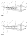
- FIG. 1 shows the schematic structure of a Lummer Gehrcke plate 1 as part of a Lummer Gehrke interferometer.
- Two plane-parallel aligned electrodes 3 and 4 are arranged on opposite sides of a dielectric elastomer 2.
- the electrodes 3 and 4 are connected by means not shown electrical connection means to a circuit.
- the thickness of the Lummer-Gehrcke plate 1 results at rest, ie without a voltage applied to the electrodes 3 and 4 via the circuit voltage through the thickness of the dielectric elastomer 2. For simplicity, light refraction effects at the interfaces to the electrodes 3, 4 were not shown separately.
- Light 6 from a light source now enters at a certain angle into a prism 5 located on one side of the dielectric elastomer 2 and is deflected by it by its refractive properties, so that it is deflected at a correspondingly different angle the dielectric elastomer 2 enters. In this it is now partially reflected at the interfaces.
- the exiting light beams 7 are collimated via a lens 8, focused on a point 9 and brought to interference.
- suitable detector such as a photomultiplier or CCD sensor may be provided.
- the beam paths through the lens 8 have been shown only schematically.
- the interference in the spectrum depends on the thickness of the Lummer Gehrcke plate 1 and the refractive index of the dielectric elastomer 2.
- the dielectric elastomer 2 changes its extent, thereby changing the thickness.
- the dielectric elastomer 2 changes its refractive index depending on the material used and the voltage applied. Both effects lead to a change in the diffraction of the incident light, so that by applying different voltages, the interference and thereby the emission maxima of the emitted light can be changed.
- these electrodes should be as transparent as possible to light of the corresponding wavelength.
- ITO indium-tin-oxide
- recesses are provided for exiting light rays.
- FIG. 2 shows the same Lummer Gehrcke record as in FIG. 1 , with the hatching for the material of the dielectric elastomer layer 2 and the electrodes 3, 4 omitted for clarity. For this purpose, reflections of the light beam within the elastomer 2 are shown schematically.
- FIG. 3 shows the schematic structure of another Lummer Gehrke plate as part of a Lummer Gehrke interferometer. Unlike in FIG. 1 The plate now shown electrodes are now arranged so that light emerging from the elastomer 2 7 no longer must pass through them. Rather, the electrodes are arranged laterally on the elastomer. Then escaping light can pass unhindered the top and bottom of the elastomer. The electrode 3 can be seen in plan view. Opposite on the other side of the elastomer 2, the not shown further electrode is mounted.
- FIG. 4 shows the same Lummer Gehrcke record as in FIG. 3 , with the hatching for the material of the dielectric elastomer layer 2 and the electrode 3 omitted for clarity. For this purpose, reflections of the light beam within the elastomer 2 are shown schematically.
Landscapes
- Physics & Mathematics (AREA)
- Nonlinear Science (AREA)
- General Physics & Mathematics (AREA)
- Optics & Photonics (AREA)
- Compositions Of Macromolecular Compounds (AREA)
Priority Applications (1)
| Application Number | Priority Date | Filing Date | Title |
|---|---|---|---|
| EP10171872A EP2416205A1 (fr) | 2010-08-04 | 2010-08-04 | Plaque Lummer-Gehrcke commutable |
Applications Claiming Priority (1)
| Application Number | Priority Date | Filing Date | Title |
|---|---|---|---|
| EP10171872A EP2416205A1 (fr) | 2010-08-04 | 2010-08-04 | Plaque Lummer-Gehrcke commutable |
Publications (1)
| Publication Number | Publication Date |
|---|---|
| EP2416205A1 true EP2416205A1 (fr) | 2012-02-08 |
Family
ID=42937326
Family Applications (1)
| Application Number | Title | Priority Date | Filing Date |
|---|---|---|---|
| EP10171872A Withdrawn EP2416205A1 (fr) | 2010-08-04 | 2010-08-04 | Plaque Lummer-Gehrcke commutable |
Country Status (1)
| Country | Link |
|---|---|
| EP (1) | EP2416205A1 (fr) |
Citations (10)
| Publication number | Priority date | Publication date | Assignee | Title |
|---|---|---|---|---|
| US3506334A (en) * | 1966-02-17 | 1970-04-14 | Zenith Radio Corp | Phased array-type beam scanning |
| US5158922A (en) | 1992-02-04 | 1992-10-27 | Arco Chemical Technology, L.P. | Process for preparing metal cyanide complex catalyst |
| EP0654302A1 (fr) | 1993-11-23 | 1995-05-24 | ARCO Chemical Technology, L.P. | Catalyseur amélioré à base de complexe de cyanure métallique double |
| WO2001006575A1 (fr) | 1999-07-20 | 2001-01-25 | Sri International | Polymeres electroactifs ameliores |
| US6188160B1 (en) | 1997-09-12 | 2001-02-13 | University Of Kentucky Research Foundation | Smart material control system and related method |
| US20030090679A1 (en) * | 1998-03-06 | 2003-05-15 | Richard L. Scully | Ultra small spot generator |
| DE102004012094A1 (de) * | 2004-03-05 | 2005-09-29 | Siemens Ag | Adaptives optisches Element mit einem Polymeraktor |
| WO2006127285A1 (fr) | 2005-05-26 | 2006-11-30 | Eastman Chemical Company | Pellicule micro-coextrudée modifiée par des couches piézoélectriques |
| WO2009104122A1 (fr) | 2008-02-21 | 2009-08-27 | Philips Intellectual Property & Standards Gmbh | Dispositif de projection |
| US20100171393A1 (en) * | 2008-12-10 | 2010-07-08 | The Regents Of The University Of California | Bistable electroactive polymers |
-
2010
- 2010-08-04 EP EP10171872A patent/EP2416205A1/fr not_active Withdrawn
Patent Citations (10)
| Publication number | Priority date | Publication date | Assignee | Title |
|---|---|---|---|---|
| US3506334A (en) * | 1966-02-17 | 1970-04-14 | Zenith Radio Corp | Phased array-type beam scanning |
| US5158922A (en) | 1992-02-04 | 1992-10-27 | Arco Chemical Technology, L.P. | Process for preparing metal cyanide complex catalyst |
| EP0654302A1 (fr) | 1993-11-23 | 1995-05-24 | ARCO Chemical Technology, L.P. | Catalyseur amélioré à base de complexe de cyanure métallique double |
| US6188160B1 (en) | 1997-09-12 | 2001-02-13 | University Of Kentucky Research Foundation | Smart material control system and related method |
| US20030090679A1 (en) * | 1998-03-06 | 2003-05-15 | Richard L. Scully | Ultra small spot generator |
| WO2001006575A1 (fr) | 1999-07-20 | 2001-01-25 | Sri International | Polymeres electroactifs ameliores |
| DE102004012094A1 (de) * | 2004-03-05 | 2005-09-29 | Siemens Ag | Adaptives optisches Element mit einem Polymeraktor |
| WO2006127285A1 (fr) | 2005-05-26 | 2006-11-30 | Eastman Chemical Company | Pellicule micro-coextrudée modifiée par des couches piézoélectriques |
| WO2009104122A1 (fr) | 2008-02-21 | 2009-08-27 | Philips Intellectual Property & Standards Gmbh | Dispositif de projection |
| US20100171393A1 (en) * | 2008-12-10 | 2010-07-08 | The Regents Of The University Of California | Bistable electroactive polymers |
Non-Patent Citations (1)
| Title |
|---|
| ROSSET, S. ET AL.: "Metal Ion Implantation for the Fabrication of Stretchable Electrodes on Elastomers", ADV. FUNCT. MATER., vol. 19, 2009, pages 470 - 478 |
Similar Documents
| Publication | Publication Date | Title |
|---|---|---|
| EP2400573A1 (fr) | Convertisseur électromécanique, son procédé de fabrication et d'utilisation | |
| EP2459611B1 (fr) | Convertisseur électromécanique doté d'un élément polymère basé sur un mélange en polyisocyanate et de pré-polymères fonctionnels avec de l'isocyanate et sur une liaison dotée d'au moins deux groupes hydroxy réactifs à isocyanate | |
| EP2371887B1 (fr) | Matériau polymère comprenant un polymère et nanoparticule d'argent y étant dispersée | |
| DE4326196C2 (de) | Planarer elektro-optischer Lichtstrahlablenker und Verfahren zu seiner Herstellung | |
| DE3020645C2 (de) | Flüssigkristallanzeige und Verfahren zu ihrer Herstellung | |
| EP2232601B1 (fr) | Convertisseur d'énergie composé de dispersions filmogènes aqueuses de polyuréthane | |
| WO2005085930A1 (fr) | Element optique adaptatif comportant un actionneur polymere | |
| EP3545025B1 (fr) | Procédé de fabrication d'un objet revêtu au moins partiellement | |
| DE212017000044U1 (de) | Filmkondensator sowie Film für Kondensator | |
| EP2182559A1 (fr) | Convertisseur d'énergie à base de solutions de polyuréthane | |
| EP2154167A1 (fr) | Convertisseur électromécanique doté d'un élément polymère à base de polyisocyanate | |
| DE19624276A1 (de) | Phasenmodulierende Mikrostrukturen für höchstintegrierte Flächenlichtmodulatoren | |
| EP2418231A1 (fr) | Convertisseur électromécanique comprenant un polymère de polyuréthane doté d'unités de polycarbonate | |
| EP2416111A1 (fr) | Elément optique commutable pour un interféromètre | |
| EP2416207A1 (fr) | Système de modulation optique commutable | |
| EP2416205A1 (fr) | Plaque Lummer-Gehrcke commutable | |
| EP2416206A1 (fr) | Interféromètre commutable | |
| WO2012152500A1 (fr) | Procédé de sérigraphie à l'aide d'une encre d'impression réagissant pour devenir un polymère polyuréthane | |
| EP2368935B1 (fr) | Composite à couches de polymère ayant une adhérence des couches améliorée | |
| EP1350137B1 (fr) | Element de compensation optique | |
| EP3098248A1 (fr) | Additif polymère non lié destiné à l'augmentation de la constante diélectrique dans des polymères de polyuréthane électroactif | |
| WO2013113846A1 (fr) | Convertisseur électromécanique comprenant un polymère de polyuréthane à motifs polyester et/ou polycarbonate | |
| WO2004096695A2 (fr) | Composant optoélectronique à actionnement micromécanique | |
| DE102016121792A1 (de) | Vorrichtung und Verfahren zur Steuerung eines Übergangs von Licht zwischen Lichtwellenleitern | |
| WO2019166648A1 (fr) | Dispositif actionneur pour une éolienne, éolienne et procédé de montage |
Legal Events
| Date | Code | Title | Description |
|---|---|---|---|
| AK | Designated contracting states |
Kind code of ref document: A1 Designated state(s): AL AT BE BG CH CY CZ DE DK EE ES FI FR GB GR HR HU IE IS IT LI LT LU LV MC MK MT NL NO PL PT RO SE SI SK SM TR |
|
| AX | Request for extension of the european patent |
Extension state: BA ME RS |
|
| PUAI | Public reference made under article 153(3) epc to a published international application that has entered the european phase |
Free format text: ORIGINAL CODE: 0009012 |
|
| STAA | Information on the status of an ep patent application or granted ep patent |
Free format text: STATUS: THE APPLICATION HAS BEEN WITHDRAWN |
|
| 18W | Application withdrawn |
Effective date: 20120210 |