EP2416202A1 - Device for stabilizing a light beam or images - Google Patents
Device for stabilizing a light beam or images Download PDFInfo
- Publication number
- EP2416202A1 EP2416202A1 EP10758079A EP10758079A EP2416202A1 EP 2416202 A1 EP2416202 A1 EP 2416202A1 EP 10758079 A EP10758079 A EP 10758079A EP 10758079 A EP10758079 A EP 10758079A EP 2416202 A1 EP2416202 A1 EP 2416202A1
- Authority
- EP
- European Patent Office
- Prior art keywords
- light beam
- stabilizing
- stabilized
- mirror
- images
- Prior art date
- Legal status (The legal status is an assumption and is not a legal conclusion. Google has not performed a legal analysis and makes no representation as to the accuracy of the status listed.)
- Withdrawn
Links
Images
Classifications
-
- G—PHYSICS
- G02—OPTICS
- G02B—OPTICAL ELEMENTS, SYSTEMS OR APPARATUS
- G02B27/00—Optical systems or apparatus not provided for by any of the groups G02B1/00 - G02B26/00, G02B30/00
- G02B27/64—Imaging systems using optical elements for stabilisation of the lateral and angular position of the image
- G02B27/644—Imaging systems using optical elements for stabilisation of the lateral and angular position of the image compensating for large deviations, e.g. maintaining a fixed line of sight while a vehicle on which the system is mounted changes course
-
- G—PHYSICS
- G02—OPTICS
- G02B—OPTICAL ELEMENTS, SYSTEMS OR APPARATUS
- G02B27/00—Optical systems or apparatus not provided for by any of the groups G02B1/00 - G02B26/00, G02B30/00
- G02B27/64—Imaging systems using optical elements for stabilisation of the lateral and angular position of the image
-
- G—PHYSICS
- G03—PHOTOGRAPHY; CINEMATOGRAPHY; ANALOGOUS TECHNIQUES USING WAVES OTHER THAN OPTICAL WAVES; ELECTROGRAPHY; HOLOGRAPHY
- G03B—APPARATUS OR ARRANGEMENTS FOR TAKING PHOTOGRAPHS OR FOR PROJECTING OR VIEWING THEM; APPARATUS OR ARRANGEMENTS EMPLOYING ANALOGOUS TECHNIQUES USING WAVES OTHER THAN OPTICAL WAVES; ACCESSORIES THEREFOR
- G03B2205/00—Adjustment of optical system relative to image or object surface other than for focusing
- G03B2205/0007—Movement of one or more optical elements for control of motion blur
-
- G—PHYSICS
- G03—PHOTOGRAPHY; CINEMATOGRAPHY; ANALOGOUS TECHNIQUES USING WAVES OTHER THAN OPTICAL WAVES; ELECTROGRAPHY; HOLOGRAPHY
- G03B—APPARATUS OR ARRANGEMENTS FOR TAKING PHOTOGRAPHS OR FOR PROJECTING OR VIEWING THEM; APPARATUS OR ARRANGEMENTS EMPLOYING ANALOGOUS TECHNIQUES USING WAVES OTHER THAN OPTICAL WAVES; ACCESSORIES THEREFOR
- G03B2217/00—Details of cameras or camera bodies; Accessories therefor
- G03B2217/005—Blur detection
Definitions
- the present invention develops a device for stabilizing light beams or images, for instance for a laser emitter, an image-receiving camera, wherein said mechanism has been dissociated from the object to be stabilized and incorporates both the control and access means to a power supply external to the device.
- the goal is to provide means for correcting the vibrations, shaking or movements of the supporting means of said emitter or camera, as appropriate, relative to the Pan and Tilt axes mainly.
- the main object of the present invention is to provide a stabilizer for film cameras, laser emitters, pulsed laser beam emitters, or light beam emitters, having fixed dimensions and weights that are unrelated to the object to be stabilized.
- Device for stabilizing light beams or images of the type suitable for laser emitters, light beam emitters or the reception of images provided with means for detecting movements in several axes, coders for the latter and driving means for correcting the unwanted movements of the object to be stabilized, wherein said light beam is aimed at a movable mirror supported on a structure having several degrees of freedom, motorized actuators for performing mirror movements at the respective axes, coders for said movements and gyroscopic mechanisms for detecting the unwanted movements of said axes.
- the light beam passes through a hollow motor and becomes reflected on the mirror.
- the electric connections and the control circuitry of the different elements of the device rest on brushes that permit contact with movement of the parts in an unlimited 360° arc.
- the assembly is enclosed in a transparent glass sphere for protection thereof against dust, air, water, etc.
- the present invention consists of a device for stabilizing a light beam or images, of the type suitable for light beam emitters or the reception of images, laser emitters, pulsed laser beam emitters, it being provided with means for detecting movements in several axes, coders for the latter and driving means for correcting the unwanted movements of the object (1) to be stabilized, wherein said light beam (2) is aimed at a movable mirror (4).
- the movable mirror (4) of approximately triangular shape, is a surface that is stabilized against movements. It is swingingly supported on a support (5) that incorporates a coder (10) for the Tilt movement axis of the mirror (4).
- the movable assembly that includes the mirror (4), also incorporates counterweight sets (7) for facilitating the stability of the movements thereof. Movement of the Tilt axis is governed by a motor (6) of said axis, the information received from a Tilt stabilizing gyroscope (10) being included in the control means of the actuators on said Tilt movement.
- This assembly is mounted on a base having freedom of movement on the PAN axis, said movements being provided by a hollow-shaft Pan motor (3). That is possible because said mechanism offers room or the inner hollow-shaft for passage of the light beam, either of the emitting or the receiving type, between the camera or emitting apparatus (1) and said stabilizing mirror (4), said passage permitting the Pan rotary movement of the stabilizer.
- the invention permits an unlimited 360° Pan movement. Said movement is then possible, there being maintained at the same time the electric connection functions of the stabilizer with the exterior as well as the passage of the corresponding connections to the control means of the actuators of said stabilizer, thanks to a set of brushes, not shown, known in the prior art.
- the preferred embodiment utilizes conventional gyroscopes for the movement detection that is necessary for the stabilization. It is within the scope of the invention any other means for detecting movements that is either fitting in terms of implementation costs and efficiency of the outcome or that is already known or any future evolution thereof inasmuch as they are being utilized in the present invention despite not being explicitly claimed therein. For instance, gyroscopes made of optical fiber, laser ring gyroscopes, quantum gyroscopes, etc.
- Pan stabilizing gyroscope element (12) is associated to the support (5) of said mirror (4).
- the stabilizing assembly is enclosed within a transparent sphere (8) for protecting it from the external elements that might affect the functioning thereof: dust, air, water, etc.
- the invention provides a device for stabilization of fixed dimensions and size that can be coupled to a camera or filming device, a light-emitting apparatus, for instance a laser emitter, and that can produce the stabilization thereof, said device being disassociated from the apparatus to be stabilized and being thus independent of the size and weight thereof.
- said laser emitter can be for instance a pulsed laser beam emitter used in the detection of distances and positions such that the device of the invention can be utilized in the stabilization of said type of apparatus.
Abstract
Device for stabilizing a light beam or images of the type that can be used to stabilize film cameras or light beam emitters, such as a laser emitter or a pulsed laser beam emitter, which includes means for detecting movements in several axes, means for coding the latter and driving means for correcting the unwanted movements of the object to be stabilized (1), in which a stabilized mirror (4) is arranged, upon which the light beam (2) falls, which light beam related the object to be stabilized (1) to the lens captured or emitted by said light beam (2); said device includes a base with a hollow-shaft pan motor (3) which allows said light beam (2) to pass.
Description
- The present invention develops a device for stabilizing light beams or images, for instance for a laser emitter, an image-receiving camera, wherein said mechanism has been dissociated from the object to be stabilized and incorporates both the control and access means to a power supply external to the device.
- Numerous systems and devices intended to stabilize objects are known. In essence these devices comprise means for detecting movement of the object to be stabilized and driving means whose purpose is correcting said movements.
- In the field of optics and specifically in the field of the stabilization of film cameras or light beam emitters, the goal, once the point at which said receiving camera or said light beam is to be aimed has been determined, is to provide means for correcting the vibrations, shaking or movements of the supporting means of said emitter or camera, as appropriate, relative to the Pan and Tilt axes mainly.
- The problem posed by the known art is that already existing stabilizers are intended to anticipate the weight of the object to be stabilized such that all the stabilization parameters are contingent upon both said weight and size of the stabilized object.
- The main object of the present invention is to provide a stabilizer for film cameras, laser emitters, pulsed laser beam emitters, or light beam emitters, having fixed dimensions and weights that are unrelated to the object to be stabilized.
- These and other advantages of the present invention will become more apparent throughout the appended description thereof.
- Device for stabilizing light beams or images of the type suitable for laser emitters, light beam emitters or the reception of images, provided with means for detecting movements in several axes, coders for the latter and driving means for correcting the unwanted movements of the object to be stabilized, wherein said light beam is aimed at a movable mirror supported on a structure having several degrees of freedom, motorized actuators for performing mirror movements at the respective axes, coders for said movements and gyroscopic mechanisms for detecting the unwanted movements of said axes.
- The light beam passes through a hollow motor and becomes reflected on the mirror. The electric connections and the control circuitry of the different elements of the device rest on brushes that permit contact with movement of the parts in an unlimited 360° arc.
- The assembly is enclosed in a transparent glass sphere for protection thereof against dust, air, water, etc.
- For a better understanding of the invention it is accompanied by one sheet of merely illustrative and nonlimiting drawings.
-
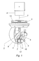
Figure 1 is a diagrammatic representation of the device in accordance with the present invention wherein part of the glass sphere has been removed thereby it showing the different elements participating in the device. -
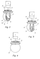
Figures 2 and 3 are other representations of the device shown infigure 1 , with the glass sphere sectioned as well so as to permit seeing the interior thereof, it displaying different side positions or mirror positions in order to more clearly appreciate, in each case, the different elements forming it. -
Figure 4 is another representation of the embodiment of the previous figures wherein the device is fitted with the protective transparent sphere thereof. - The present invention consists of a device for stabilizing a light beam or images, of the type suitable for light beam emitters or the reception of images, laser emitters, pulsed laser beam emitters, it being provided with means for detecting movements in several axes, coders for the latter and driving means for correcting the unwanted movements of the object (1) to be stabilized, wherein said light beam (2) is aimed at a movable mirror (4).
- The movable mirror (4), of approximately triangular shape, is a surface that is stabilized against movements. It is swingingly supported on a support (5) that incorporates a coder (10) for the Tilt movement axis of the mirror (4).
- The movable assembly, that includes the mirror (4), also incorporates counterweight sets (7) for facilitating the stability of the movements thereof. Movement of the Tilt axis is governed by a motor (6) of said axis, the information received from a Tilt stabilizing gyroscope (10) being included in the control means of the actuators on said Tilt movement.
- This assembly is mounted on a base having freedom of movement on the PAN axis, said movements being provided by a hollow-shaft Pan motor (3). That is possible because said mechanism offers room or the inner hollow-shaft for passage of the light beam, either of the emitting or the receiving type, between the camera or emitting apparatus (1) and said stabilizing mirror (4), said passage permitting the Pan rotary movement of the stabilizer.
- The invention permits an unlimited 360° Pan movement. Said movement is then possible, there being maintained at the same time the electric connection functions of the stabilizer with the exterior as well as the passage of the corresponding connections to the control means of the actuators of said stabilizer, thanks to a set of brushes, not shown, known in the prior art.
- It could also be used any other means for performing said transmission of data and commands, such as wireless transmission, without it affecting the essence of the invention.
- The preferred embodiment utilizes conventional gyroscopes for the movement detection that is necessary for the stabilization. It is within the scope of the invention any other means for detecting movements that is either fitting in terms of implementation costs and efficiency of the outcome or that is already known or any future evolution thereof inasmuch as they are being utilized in the present invention despite not being explicitly claimed therein. For instance, gyroscopes made of optical fiber, laser ring gyroscopes, quantum gyroscopes, etc.
- In said Pan mechanism it is included the corresponding coder (13) therefor. In the drawings of the above-described preferred embodiment the Pan stabilizing gyroscope element (12) is associated to the support (5) of said mirror (4).
- The stabilizing assembly is enclosed within a transparent sphere (8) for protecting it from the external elements that might affect the functioning thereof: dust, air, water, etc.
- In this way the invention provides a device for stabilization of fixed dimensions and size that can be coupled to a camera or filming device, a light-emitting apparatus, for instance a laser emitter, and that can produce the stabilization thereof, said device being disassociated from the apparatus to be stabilized and being thus independent of the size and weight thereof.
- In another embodiment, said laser emitter can be for instance a pulsed laser beam emitter used in the detection of distances and positions such that the device of the invention can be utilized in the stabilization of said type of apparatus.
- It is understood that finish or shape details in the present case are liable to variation provided that the essence of the invention is not altered.
Claims (5)
- DEVICE FOR STABILIZING A LIGHT BEAM OR IMAGES, of the type that can be used to stabilize film cameras or light beam emitters, such as laser emitters, pulsed laser beam emitters including means for detecting movements in several axes, coders for the latter and driving means for correcting the unwanted movements of the object to be stabilized (1) CHARACTERIZED in that- it comprises a stabilized mirror (4) upon which the light beam (2) falls for connecting the object to be stabilized (1) with the target, either received or emitted, by said light beam (2);- it is provided with said stabilized mirror (4) that is supported on a support (5) capable of moving said mirror (4) on the TILT axis, there being provided a motor (6) for said TILT axis, means for detection of movement through gyroscopes (11) that stabilize said TILT movement and coders (10) for said movement;- the aforesaid assembly is mounted on a base having 360° freedom of movement on the PAN axis and includes a hollow-shaft PAN motor (3) that permits the passage of said light beam (2); it also being provided with a coder (13) therefor and a PAN-stabilizing gyroscope (12).
- DEVICE FOR STABILIZING A LIGHT BEAM OR IMAGES, according to the previous claim, CHARACTERIZED in that said assembly of said stabilized mirror (4) incorporates a set of counterweights (7) of said mirror (4).
- DEVICE FOR STABILIZING A LIGHT BEAM OR IMAGES, according to the previous claims, CHARACTERIZED in that said Pan-stabilizing gyroscope element (12) is associated to the support (5) of said mirror (4).
- DEVICE FOR STABILIZING A LIGHT BEAM OR IMAGES, according to the previous claims, CHARACTERIZED in that the electric connection functions of the stabilizing device with the exterior as well as the passage of the corresponding connections to the control means of the actuators of said stabilizer are performed thanks to a set of brushes.
- DEVICE FOR STABILIZING A LIGHT BEAM OR IMAGES, according to the previous claims, CHARACERIZED in that said stabilizing device is enclosed within a transparent sphere (8).
Applications Claiming Priority (2)
| Application Number | Priority Date | Filing Date | Title |
|---|---|---|---|
| ES200900940A ES2345807B1 (en) | 2009-03-31 | 2009-03-31 | STABILIZING DEVICE OF A BEAM OF LIGHT OR IMAGES. |
| PCT/ES2010/000040 WO2010112631A1 (en) | 2009-03-31 | 2010-02-02 | Device for stabilizing a light beam or images |
Publications (2)
| Publication Number | Publication Date |
|---|---|
| EP2416202A1 true EP2416202A1 (en) | 2012-02-08 |
| EP2416202A4 EP2416202A4 (en) | 2017-12-06 |
Family
ID=42734899
Family Applications (1)
| Application Number | Title | Priority Date | Filing Date |
|---|---|---|---|
| EP10758079.7A Withdrawn EP2416202A4 (en) | 2009-03-31 | 2010-02-02 | Device for stabilizing a light beam or images |
Country Status (4)
| Country | Link |
|---|---|
| US (1) | US20120019911A1 (en) |
| EP (1) | EP2416202A4 (en) |
| ES (1) | ES2345807B1 (en) |
| WO (1) | WO2010112631A1 (en) |
Cited By (5)
| Publication number | Priority date | Publication date | Assignee | Title |
|---|---|---|---|---|
| DE202014009181U1 (en) | 2014-11-18 | 2015-01-12 | Marc Fellinger | Device for movably mounting a camera |
| DE102014016987A1 (en) | 2014-11-18 | 2016-05-19 | Mark Fellinger | Device for movably mounting a camera |
| DE102018009279B3 (en) | 2018-11-23 | 2019-12-19 | Mark Fellinger | Device for holding a camera or other components |
| DE102018009606B3 (en) | 2018-12-06 | 2019-12-24 | Mark Fellinger | Device for holding a camera system on moving objects |
| DE202021001556U1 (en) | 2021-04-28 | 2021-07-23 | Marc Fellinger | Device for holding a camera system |
Family Cites Families (8)
| Publication number | Priority date | Publication date | Assignee | Title |
|---|---|---|---|---|
| US3468595A (en) * | 1966-08-29 | 1969-09-23 | Optical Res & Dev Corp | Optical stabilization by reflecting means |
| US3612643A (en) * | 1969-07-24 | 1971-10-12 | Hughes Aircraft Co | Target locating system |
| US4015905A (en) * | 1976-02-18 | 1977-04-05 | Westinghouse Electric Corporation | Target sighting device |
| US4883347A (en) * | 1988-01-22 | 1989-11-28 | Hughes Aircraft Company | Stabilized pointing mirror |
| US5734515A (en) * | 1994-08-08 | 1998-03-31 | Reliance Electric Industrial Company | Apparatus for positioning an optical line of sight within a hemispheric region |
| US5806789A (en) * | 1995-08-22 | 1998-09-15 | Lockheed Corporation | Optical apparatus for an aircraft |
| GB2345155B (en) * | 1998-12-23 | 2003-04-09 | Marconi Avionics | Sightline stabilisation |
| WO2007143222A2 (en) * | 2006-06-09 | 2007-12-13 | Bae Systems Information And Electronic Systems Integration Inc. | High accuracy optical pointing apparatus |
-
2009
- 2009-03-31 ES ES200900940A patent/ES2345807B1/en not_active Expired - Fee Related
-
2010
- 2010-02-02 US US13/260,931 patent/US20120019911A1/en not_active Abandoned
- 2010-02-02 WO PCT/ES2010/000040 patent/WO2010112631A1/en active Application Filing
- 2010-02-02 EP EP10758079.7A patent/EP2416202A4/en not_active Withdrawn
Non-Patent Citations (1)
| Title |
|---|
| See references of WO2010112631A1 * |
Cited By (6)
| Publication number | Priority date | Publication date | Assignee | Title |
|---|---|---|---|---|
| DE202014009181U1 (en) | 2014-11-18 | 2015-01-12 | Marc Fellinger | Device for movably mounting a camera |
| DE102014016987A1 (en) | 2014-11-18 | 2016-05-19 | Mark Fellinger | Device for movably mounting a camera |
| DE102018009279B3 (en) | 2018-11-23 | 2019-12-19 | Mark Fellinger | Device for holding a camera or other components |
| DE102018009606B3 (en) | 2018-12-06 | 2019-12-24 | Mark Fellinger | Device for holding a camera system on moving objects |
| EP3663628A1 (en) | 2018-12-06 | 2020-06-10 | Mark Fellinger | Device for fixing a camera system to moving objects |
| DE202021001556U1 (en) | 2021-04-28 | 2021-07-23 | Marc Fellinger | Device for holding a camera system |
Also Published As
| Publication number | Publication date |
|---|---|
| WO2010112631A1 (en) | 2010-10-07 |
| ES2345807B1 (en) | 2011-07-26 |
| US20120019911A1 (en) | 2012-01-26 |
| ES2345807A1 (en) | 2010-10-01 |
| EP2416202A4 (en) | 2017-12-06 |
Similar Documents
| Publication | Publication Date | Title |
|---|---|---|
| CN110045386B (en) | Method and system for optical alignment of light detection and ranging | |
| EP2416202A1 (en) | Device for stabilizing a light beam or images | |
| EP2984519B1 (en) | Apparatus and methods for stabilization and vibration reduction | |
| WO2016059877A1 (en) | Controller, control method, and flight vehicle device | |
| US10375311B2 (en) | Anti-rotation mount | |
| US10284118B2 (en) | Two-axis angular pointing device and methods of use thereof | |
| US5917587A (en) | Automatic plumb laser beam generator | |
| KR102210083B1 (en) | Drone Control System | |
| JP6900658B2 (en) | Imaging device, image projection device and stage device | |
| WO2012170673A1 (en) | Gimbal system with a translational mount | |
| JP2018100498A (en) | Levitation type inspection device | |
| JP6793006B2 (en) | Optical unit | |
| CN115066590A (en) | Laser level and leveling method | |
| WO2019009154A1 (en) | Mobile image pickup device | |
| CN115655116B (en) | Six-dimensional laser tracking measurement system based on back tracking | |
| JP2013015580A (en) | Imaging apparatus and control method therefor | |
| CN112584053A (en) | Binocular vision laser emission system and method | |
| ES2693319T3 (en) | Guide system for missiles for vehicles and mobile targets | |
| KR101948810B1 (en) | Image Map System for Processing Based Image Data by Unmanned Aerial Vehicel | |
| JP2006266762A (en) | Tracking and sighting device | |
| WO2015146805A1 (en) | Light projection device and light projection method | |
| JP2020069892A (en) | Flight vehicle | |
| JP2010276772A (en) | Autonomous imaging apparatus | |
| JP4387871B2 (en) | Imaging device | |
| RU2708535C1 (en) | Panoramic device |
Legal Events
| Date | Code | Title | Description |
|---|---|---|---|
| PUAI | Public reference made under article 153(3) epc to a published international application that has entered the european phase |
Free format text: ORIGINAL CODE: 0009012 |
|
| 17P | Request for examination filed |
Effective date: 20110928 |
|
| AK | Designated contracting states |
Kind code of ref document: A1 Designated state(s): AT BE BG CH CY CZ DE DK EE ES FI FR GB GR HR HU IE IS IT LI LT LU LV MC MK MT NL NO PL PT RO SE SI SK SM TR |
|
| DAX | Request for extension of the european patent (deleted) | ||
| RA4 | Supplementary search report drawn up and despatched (corrected) |
Effective date: 20171106 |
|
| RIC1 | Information provided on ipc code assigned before grant |
Ipc: G02B 27/64 20060101AFI20171027BHEP |
|
| STAA | Information on the status of an ep patent application or granted ep patent |
Free format text: STATUS: THE APPLICATION IS DEEMED TO BE WITHDRAWN |
|
| 18D | Application deemed to be withdrawn |
Effective date: 20180605 |