EP2415981A1 - Hydraulic drive apparatus for construction equipment - Google Patents
Hydraulic drive apparatus for construction equipment Download PDFInfo
- Publication number
- EP2415981A1 EP2415981A1 EP10753494A EP10753494A EP2415981A1 EP 2415981 A1 EP2415981 A1 EP 2415981A1 EP 10753494 A EP10753494 A EP 10753494A EP 10753494 A EP10753494 A EP 10753494A EP 2415981 A1 EP2415981 A1 EP 2415981A1
- Authority
- EP
- European Patent Office
- Prior art keywords
- hydraulic
- forced regeneration
- travel
- work
- operated
- Prior art date
- Legal status (The legal status is an assumption and is not a legal conclusion. Google has not performed a legal analysis and makes no representation as to the accuracy of the status listed.)
- Withdrawn
Links
Images



Classifications
-
- F—MECHANICAL ENGINEERING; LIGHTING; HEATING; WEAPONS; BLASTING
- F02—COMBUSTION ENGINES; HOT-GAS OR COMBUSTION-PRODUCT ENGINE PLANTS
- F02D—CONTROLLING COMBUSTION ENGINES
- F02D41/00—Electrical control of supply of combustible mixture or its constituents
- F02D41/02—Circuit arrangements for generating control signals
- F02D41/021—Introducing corrections for particular conditions exterior to the engine
- F02D41/0235—Introducing corrections for particular conditions exterior to the engine in relation with the state of the exhaust gas treating apparatus
- F02D41/024—Introducing corrections for particular conditions exterior to the engine in relation with the state of the exhaust gas treating apparatus to increase temperature of the exhaust gas treating apparatus
- F02D41/0245—Introducing corrections for particular conditions exterior to the engine in relation with the state of the exhaust gas treating apparatus to increase temperature of the exhaust gas treating apparatus by increasing temperature of the exhaust gas leaving the engine
-
- E—FIXED CONSTRUCTIONS
- E02—HYDRAULIC ENGINEERING; FOUNDATIONS; SOIL SHIFTING
- E02F—DREDGING; SOIL-SHIFTING
- E02F9/00—Component parts of dredgers or soil-shifting machines, not restricted to one of the kinds covered by groups E02F3/00 - E02F7/00
- E02F9/20—Drives; Control devices
- E02F9/22—Hydraulic or pneumatic drives
- E02F9/226—Safety arrangements, e.g. hydraulic driven fans, preventing cavitation, leakage, overheating
-
- E—FIXED CONSTRUCTIONS
- E02—HYDRAULIC ENGINEERING; FOUNDATIONS; SOIL SHIFTING
- E02F—DREDGING; SOIL-SHIFTING
- E02F9/00—Component parts of dredgers or soil-shifting machines, not restricted to one of the kinds covered by groups E02F3/00 - E02F7/00
- E02F9/20—Drives; Control devices
- E02F9/22—Hydraulic or pneumatic drives
- E02F9/2278—Hydraulic circuits
- E02F9/2282—Systems using center bypass type changeover valves
-
- E—FIXED CONSTRUCTIONS
- E02—HYDRAULIC ENGINEERING; FOUNDATIONS; SOIL SHIFTING
- E02F—DREDGING; SOIL-SHIFTING
- E02F9/00—Component parts of dredgers or soil-shifting machines, not restricted to one of the kinds covered by groups E02F3/00 - E02F7/00
- E02F9/20—Drives; Control devices
- E02F9/22—Hydraulic or pneumatic drives
- E02F9/2278—Hydraulic circuits
- E02F9/2285—Pilot-operated systems
-
- E—FIXED CONSTRUCTIONS
- E02—HYDRAULIC ENGINEERING; FOUNDATIONS; SOIL SHIFTING
- E02F—DREDGING; SOIL-SHIFTING
- E02F9/00—Component parts of dredgers or soil-shifting machines, not restricted to one of the kinds covered by groups E02F3/00 - E02F7/00
- E02F9/20—Drives; Control devices
- E02F9/22—Hydraulic or pneumatic drives
- E02F9/2278—Hydraulic circuits
- E02F9/2296—Systems with a variable displacement pump
-
- E—FIXED CONSTRUCTIONS
- E02—HYDRAULIC ENGINEERING; FOUNDATIONS; SOIL SHIFTING
- E02F—DREDGING; SOIL-SHIFTING
- E02F9/00—Component parts of dredgers or soil-shifting machines, not restricted to one of the kinds covered by groups E02F3/00 - E02F7/00
- E02F9/26—Indicating devices
- E02F9/264—Sensors and their calibration for indicating the position of the work tool
- E02F9/265—Sensors and their calibration for indicating the position of the work tool with follow-up actions (e.g. control signals sent to actuate the work tool)
-
- F—MECHANICAL ENGINEERING; LIGHTING; HEATING; WEAPONS; BLASTING
- F02—COMBUSTION ENGINES; HOT-GAS OR COMBUSTION-PRODUCT ENGINE PLANTS
- F02D—CONTROLLING COMBUSTION ENGINES
- F02D41/00—Electrical control of supply of combustible mixture or its constituents
- F02D41/02—Circuit arrangements for generating control signals
- F02D41/021—Introducing corrections for particular conditions exterior to the engine
- F02D41/0235—Introducing corrections for particular conditions exterior to the engine in relation with the state of the exhaust gas treating apparatus
- F02D41/027—Introducing corrections for particular conditions exterior to the engine in relation with the state of the exhaust gas treating apparatus to purge or regenerate the exhaust gas treating apparatus
- F02D41/029—Introducing corrections for particular conditions exterior to the engine in relation with the state of the exhaust gas treating apparatus to purge or regenerate the exhaust gas treating apparatus the exhaust gas treating apparatus being a particulate filter
-
- F—MECHANICAL ENGINEERING; LIGHTING; HEATING; WEAPONS; BLASTING
- F15—FLUID-PRESSURE ACTUATORS; HYDRAULICS OR PNEUMATICS IN GENERAL
- F15B—SYSTEMS ACTING BY MEANS OF FLUIDS IN GENERAL; FLUID-PRESSURE ACTUATORS, e.g. SERVOMOTORS; DETAILS OF FLUID-PRESSURE SYSTEMS, NOT OTHERWISE PROVIDED FOR
- F15B11/00—Servomotor systems without provision for follow-up action ; Circuits therefor
- F15B11/02—Systems essentially incorporating special features for controlling the speed or the actuating force of an output member
- F15B11/024—Systems essentially incorporating special features for controlling the speed or the actuating force of an output member by means of differential connection of the servomotor lines, e.g. regenerative circuits
-
- F—MECHANICAL ENGINEERING; LIGHTING; HEATING; WEAPONS; BLASTING
- F15—FLUID-PRESSURE ACTUATORS; HYDRAULICS OR PNEUMATICS IN GENERAL
- F15B—SYSTEMS ACTING BY MEANS OF FLUIDS IN GENERAL; FLUID-PRESSURE ACTUATORS, e.g. SERVOMOTORS; DETAILS OF FLUID-PRESSURE SYSTEMS, NOT OTHERWISE PROVIDED FOR
- F15B21/00—Common features of fluid actuator systems; Fluid-pressure actuator systems or details thereof, not covered by any other group of this subclass
- F15B21/14—Energy-recuperation means
-
- F—MECHANICAL ENGINEERING; LIGHTING; HEATING; WEAPONS; BLASTING
- F02—COMBUSTION ENGINES; HOT-GAS OR COMBUSTION-PRODUCT ENGINE PLANTS
- F02D—CONTROLLING COMBUSTION ENGINES
- F02D41/00—Electrical control of supply of combustible mixture or its constituents
- F02D41/02—Circuit arrangements for generating control signals
- F02D41/021—Introducing corrections for particular conditions exterior to the engine
- F02D41/0235—Introducing corrections for particular conditions exterior to the engine in relation with the state of the exhaust gas treating apparatus
- F02D41/024—Introducing corrections for particular conditions exterior to the engine in relation with the state of the exhaust gas treating apparatus to increase temperature of the exhaust gas treating apparatus
- F02D2041/026—Introducing corrections for particular conditions exterior to the engine in relation with the state of the exhaust gas treating apparatus to increase temperature of the exhaust gas treating apparatus using an external load, e.g. by increasing generator load or by changing the gear ratio
-
- F—MECHANICAL ENGINEERING; LIGHTING; HEATING; WEAPONS; BLASTING
- F02—COMBUSTION ENGINES; HOT-GAS OR COMBUSTION-PRODUCT ENGINE PLANTS
- F02D—CONTROLLING COMBUSTION ENGINES
- F02D2200/00—Input parameters for engine control
- F02D2200/60—Input parameters for engine control said parameters being related to the driver demands or status
- F02D2200/604—Engine control mode selected by driver, e.g. to manually start particle filter regeneration or to select driving style
-
- Y—GENERAL TAGGING OF NEW TECHNOLOGICAL DEVELOPMENTS; GENERAL TAGGING OF CROSS-SECTIONAL TECHNOLOGIES SPANNING OVER SEVERAL SECTIONS OF THE IPC; TECHNICAL SUBJECTS COVERED BY FORMER USPC CROSS-REFERENCE ART COLLECTIONS [XRACs] AND DIGESTS
- Y02—TECHNOLOGIES OR APPLICATIONS FOR MITIGATION OR ADAPTATION AGAINST CLIMATE CHANGE
- Y02T—CLIMATE CHANGE MITIGATION TECHNOLOGIES RELATED TO TRANSPORTATION
- Y02T10/00—Road transport of goods or passengers
- Y02T10/10—Internal combustion engine [ICE] based vehicles
- Y02T10/12—Improving ICE efficiencies
Definitions
- the present invention relates to a hydraulic drive system for a working machine such as a hydraulic excavator.
- the hydraulic drive system can be adopted in the working machine, is provided with an exhaust gas purification device for capturing, by a filter, particulate matter in exhaust gas produced in an engine (prime mover), and burns off particulate matter deposited on the filter to conduct so-called forced regeneration.
- a hydraulic drive system for a working machine has been designed to permit detecting clogging of a filter in an exhaust gas purification device.
- the hydraulic drive system is set to automatically conduct forced regeneration.
- This forced regeneration conducted by the hydraulic drive system increases the delivery flow rate and delivery pressure of a hydraulic pump to increase the engine output, whereby the temperature of exhaust gas is raised.
- This increase in engine output leads to a rise in the temperature of exhaust gas.
- particulate matter with which the filter is clogged is burnt with the heat of the exhaust gas and is removed from the filter (see Patent Document 1).
- the present invention has as an object thereof the provision of a hydraulic drive system for a working machine, which can provide improved safety during forced regeneration.
- the present invention is constituted as will be described next.
- the present invention is characterized in that in a hydraulic drive system for a working machine, said hydraulic drive system being provided with plural work hydraulic actuators for driving a work element constituting the working machine, a hydraulic pressure source for producing, by a hydraulic pump, pressure oil to be fed to the plural work hydraulic actuators, an engine as a drive source for the hydraulic pump, an exhaust gas purification device for capturing, by a filter, particulate matter in exhaust gas produced by the engine, a forced regeneration means for burning particulate matter deposited on the filter, and a control means for controlling the forced regeneration means, wherein the hydraulic drive system is further provided with a forced regeneration command means for commanding conduct of forced regeneration when operated, an attitude detection means for detecting a proper attitude specified beforehand as a safe attitude of the work element during forced regeneration, and a non-operated state detection means for detecting that all the hydraulic actuators for driving the working machine, said hydraulic actuators including the plural work hydraulic actuators, are in non-operated states; and taking as conditions for the conduct of forced regeneration that the non-operated
- the present invention as described above in [1], it is set as conditions for conducting forced regeneration that non-operated states of all the work hydraulic actuators have been detected by the non-operated state detection means and the proper attitude of the work element has been detected by the attitude detection means. Unless the work element has taken the pre-specified proper attitude as its safe attitude during forced regeneration, it is thus possible to prevent conducting forced regeneration even when all the work hydraulic actuators are in non-operated states. Accordingly, the working machine can be provided with improved safety during forced regeneration.
- the present invention may also be characterized in that in the invention as described above in [1], the plural work hydraulic actuators are single-rod hydraulic cylinders; control valves are arranged between the hydraulic pressure source and respective ones of the plural work hydraulic cylinders such that the control valves are switchable between feed states, in which pressure oil is fed from the hydraulic pressure source to the work hydraulic cylinders, and non-feed states, in which pressure oil is guided from the hydraulic pressure source to a hydraulic oil reservoir while cutting off flows of pressure oil from the hydraulic pressure source to the work hydraulic cylinders; the forced regeneration means has a boosting means capable of raising a delivery pressure of the hydraulic pump to a predetermined pressure by restricting lines downstream of all the control valves when all the control valves are in the non-feed states; and the attitude detection means detects, as an attribute of the proper attitude, that a specific cylinder out of the plural work hydraulic cylinders, said specific cylinder being drivable at the predetermined pressure, is in a stroke-end state on an extended side.
- the forced regeneration means raises the delivery pressure of the pump, that is, the pressure of the hydraulic pressure source to the predetermined pressure by the boosting means upon forced regeneration.
- the respective work hydraulic cylinders and the hydraulic pressure source have been cut off by the corresponding control valves.
- a front working mechanism as a work element of a hydraulic excavator has a boom cylinder, arm cylinder and bucket cylinder as work hydraulic actuators formed of single-rod hydraulic cylinders.
- the boom cylinder is not actuated at the predetermined pressure required for forced regeneration, because the own weight of the front working mechanism always acts on the boom cylinder.
- the arm cylinder and bucket cylinder include those which may be driven at the predetermined pressure. These arm cylinder and bucket cylinder may each correspond to the specific cylinder in the present invention as described above in [2].
- the present invention may also be characterized in that in the invention as described above in [1] or [2], the control means makes the forced regeneration means stop forced regeneration when the conditions have become no longer satisfied during the conduct of forced regeneration.
- the present invention may also be characterized in that in the invention as described above in [1], the working machine is self-propelling, and has a travel hydraulic actuator as a drive source for self-traveling; actuation command means are arranged for the plural work hydraulic actuators and the travel hydraulic actuator, respectively, to produce command signals for the actuation of the respective hydraulic actuators depending on operations by corresponding parts of the body such as the hands and feet; an operation batch-invalidating means is arranged to create, in a batch for all the operation command means, operation-invalidated states in which neither the work hydraulic actuators are actuated even when the actuation command means corresponding to the work hydraulic actuators are operated nor the travel hydraulic actuator is actuated even when the actuation command means corresponding to the travel hydraulic actuator is operated; and the non-operated state detection means detects an actuated state of the operation batch-invalidating means as the non-operated states.
- the present invention as described above in [4] has the construction provided with the operation batch-invalidating means, and this construction is commonly adopted in crawler working machines such as crawler hydraulic excavators among self-propelling working machines of different kinds. According to the present invention as described above in [4], it is hence possible to provide a hydraulic drive system of a crawler working machine with improved safety during forced regeneration.
- the present invention may also be characterized in that in the invention as described above in [1], the working machine is self-propelling, and has a travel hydraulic actuator as a drive source for self-traveling; actuation command means are arranged for the plural work hydraulic actuators and the travel hydraulic actuator, respectively, to produce command signals for the actuation of the respective hydraulic actuators depending on operations by corresponding parts of the body such as the hands and feet; a travel-operation invalidating means is arranged to create a travel-operation invalidated state in which the working machine does not travel even when the actuation command means corresponding to the travel hydraulic actuator is operated, and a work-operation invalidating means is also arranged to create a work-operation invalidated state in which the work hydraulic actuators are not actuated even when the actuation command means corresponding to the work hydraulic actuators are operated; and the non-operated state detection means detects as the non-operated states that the travel-operation invalidating means and work-operation invalidating means are both in operated states.
- the present invention as described above in [5] has the construction provided with the travel-operation invalidating means and work-operation invalidating means, and this construction is commonly adopted in wheel working machines such as wheel hydraulic excavators among self-propelling working machines of different kinds. According to the present invention as described above in [5], it is hence possible to provide a hydraulic drive system of a wheel working machine with improved safety during forced regeneration.
- the present invention may also be characterized in that in the invention as described above in [1], the work element is a front working mechanism, and a grounded attitude of the front working mechanism is included as the attribute of the proper attitude.
- the present invention it is possible, as mentioned above, to prevent conducting forced regeneration even when all the work hydraulic actuators are in non-operated states, unless the work element has taken the proper attitude pre-specified as a safe attitude during forced regeneration. Therefore, the present invention can provide the working machine with improved safety during forced regeneration.
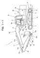
- FIG. 1-1 is a left side view of a crawler hydraulic excavator as a self-propelling working machine according to the first embodiment of the present invention.
- FIG. 1-2 is a hydraulic circuit diagram showing in a simplified form a hydraulic drive system arranged in the crawler hydraulic excavator shown in FIG. 1-1 .
- FIG. 1-3 is a flow chart illustrating a flow of processing to be performed at a controller depicted in FIG. 1-2 .
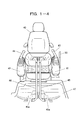
- FIG. 1-4 is a perspective view of the inside of an operator's cab of the crawler hydraulic excavator illustrated in FIG. 1-1 , as viewed from front of and obliquely above an operator's seat.
- the crawler hydraulic excavator 1 (hereinafter simply called “the hydraulic excavator 1") is provided with a travel base 2 which runs by driving crawler tracks 3, a revolving upperstructure 8 swingably connected to the travel base 2, and a front working mechanism 12 substantially centrally arranged as a work element on a front section of the revolving upperstructure 8.
- a left side section of the travel base 2 includes a track frame 4 as a framework structure.
- a travel motor 5 is mounted, as a travel hydraulic actuator, integrally with a reduction gear box.
- the reduction gear box is arranged to drive a drive wheel 6.
- a driven wheel 7 is arranged on a front end portion of the track frame 4.
- the crawler track 3 is wrapped around the drive wheel 6 and driven wheel 7, and is located surrounding the track frame 4. By transmitting an output torque of the travel motor 5 to the crawler track 3 via the reduction gear box and drive wheel 6, the crawler track 3 is driven around the track frame 4, and as a result, the crawler hydraulic excavator 1 travels.
- its right side section Similar to the left side section of the travel base 2, its right side section also has a construction provided with a track frame, travel motor (travel hydraulic actuator), drive wheel, driven wheel and crawler track.
- an operator's cab 9 is mounted on a left front section of the revolving upperstructure 8.
- an engine compartment 10 Disposed behind the operator's cab 9 is an engine compartment 10, in which an engine 23 (diesel engine), main pump 22 (variable displacement hydraulic pump), and the like of a hydraulic drive system 20 to be mentioned subsequently herein are accommodated.
- an outlet pipe 26 From a top part of the engine compartment 10, an outlet pipe 26 extends to guide exhaust gas from the engine 23 outward of the hydraulic excavator 1.
- the front working mechanism 12 is provided with a boom 13.
- the boom 13 of the front working mechanism 12 is pivotally connected at one end thereof via a pin to a foot part arranged in a front section of a frame 11 that constitutes the revolving upperstructure 8.
- an arm 14 is pivotally connected at one end thereof via a pin.
- a bucket 15 is pivotally connected at one end thereof via a pin.
- sign 12a indicates a pin joint at the other end of the boom 13 and the one end of the arm 14, and sign 12b designates a pin joint at the other end of the arm 14 and the one end of the bucket 15.
- the boom 13 is drivable by a boom cylinder 16 (single-rod hydraulic cylinder) as a work hydraulic actuator.
- This boom cylinder 16 is pivotally connected at a bottom-side end of a cylinder tube 16a to the hoot part via a pin, and is also pivotally connected at an end of a rod 16b to an intermediate part of the boom 8 via a pin.
- the arm 14 is drivable by an arm cylinder 17 (single-rod hydraulic cylinder) as a work hydraulic actuator.
- This arm cylinder 17 is pivotally connected at a bottom-side end of a cylinder tube 17a to the boom 13 via a pin, and is also pivotally connected at an end of a rod 17b to the one end of the arm 14 via a pin.
- the bucket 15 is arranged such that an extending/retracting motion of a bucket cylinder 18 (single-rod hydraulic cylinder) as a work hydraulic actuator is transmitted via a link mechanism 18c to drive the bucket 15.
- This bucket cylinder 18 is pivotally connected at a bottom-side end of a cylinder tube 18a to the arm 14 via a pin, and is also pivotally connected at an end of a rod 18b to the link mechanism 18c via a pin.
- the hydraulic drive system 20 is provided with the left travel motor 5 and right travel motor (not shown) as travel hydraulic actuators which are a drive source for self-propelling of the hydraulic excavator 1, a swing motor (unillustrated hydraulic motor) as a work hydraulic actuator which is a drive source for the revolving upperstructure 8, the boom cylinder 16, arm cylinder 17 and bucket cylinder 18 as plural work hydraulic actuators for driving the front working mechanism 12.
- FIG. 1-2 depicts only the arm cylinder 17 and the remaining boom cylinder 16 and bucket cylinder 18 are omitted.
- a hydraulic pressure source for a drive pressure which drives these left travel motor 5, right travel motor, swing motor, boom cylinder 16, arm cylinder 17 and bucket cylinder 18, is the main pump 22.
- a drive source for this main pump 22 is the engine 23.
- An exhaust gas pipe 24 extends from the engine 23, and this exhaust gas pipe 24 is provided with an exhaust gas purification device 25.
- the exhaust gas purification device 25 serves to capture, by a filter, particulate matter in exhaust gas produced by the engine 23. From the exhaust gas purification device 25, the above-described outlet pipe 26 extends.
- FIG. 1-2 depicts, as a representative of these actuator control valves, only an arm cylinder control valve 27 interposed between the main pump 22 and the arm cylinder 17.
- This arm cylinder control valve 27 is a hydraulically-piloted, spring-centered, 3-position valve. Valve positions of the arm cylinder control valve 27 are set at an initial position 27a (neutral position), first operating position 27b and second operating position 27c.
- the initial position 27a (neutral position) is a valve position, in which a passage is formed to guide the delivery oil of the main pump 22 to a hydraulic oil reservoir 21 while cutting off a flow of pressure oil from the main pump 22 to either a bottom chamber 17a1 or a rod chamber 17a2 of the arm cylinder 17, in other words, is a valve position in which the arm cylinder control valve 27 is brought into a non-feed state.
- the first operating position 27b is a valve position, in which two passages are formed, one being a passage that guides the delivery oil of the main pump 22 to the bottom chamber 17a1 of the arm cylinder 17, and the other a passage that guides pressure oil, which is contained in the rod chamber 17a2, to the hydraulic oil reservoir 21, in other words, is a valve position in which the arm cylinder control valve 27 is brought into a first feed state to extend the arm cylinder 17.
- the second operating position 27c is a valve position, in which two passages are formed, one being a passage that guides the delivery oil of the main pump 22 to the rod chamber 17a2 of the arm cylinder 17, and the other a passage that guides pressure oil, which is contained in the bottom chamber 17a1, to the hydraulic oil reservoir 21, in other words, is a valve position in which the arm cylinder control valve 27 is brought into a second feed state to contract the arm cylinder 17.
- the boom cylinder control valve and bucket cylinder control valve are of a similar construction as the arm cylinder control valve 27, the boom cylinder control valve is switchable to a non-feed state, first feed state or second feed-state with respect to the boom cylinder 16, and the bucket cylinder control valve is switchable to a non-feed state, first feed state or second feed-state with respect to the bucket cylinder 18.
- the left travel motor control valve, right travel motor control valve and swing motor control valve are of a similar construction as the arm cylinder control valve 27.
- a passage is formed to guide the delivery oil of the main pump 22 to the hydraulic oil reservoir 21 while cutting off a flow of pressure oil from the main pump 22 to any of the two inlet/outlet ports of a hydraulic motor as the travel motor or swing motor.
- two passages are formed, one being a passage that guides the delivery oil of the main pump 22 to one of the inlet/outlet ports of the hydraulic motor, and the other a passage that guides pressure oil, which has been discharged from the other one of the inlet/outlet ports, to the hydraulic oil reservoir 21.
- two passages are formed, one being a passage that guides the delivery oil of the main pump 22 to the other one of the inlet/outlet ports of the hydraulic motor, and the other a passage that guides pressure oil, which has been discharged from the one of the inlet/outlet ports of the hydraulic motor, to the hydraulic oil reservoir 21.
- the corresponding relations between the respective ones of the initial position, first operation position and second operating position and the respective ones of the non-feed state, first feed state and second feed state are similar to those in the arm cylinder control valve 27.
- a pilot pressure to be applied to the arm cylinder control valve 27 is produced by an arm control device 29.
- Designated at numeral 30 is a left travel control device, which by using the delivery pressure of the pilot pump 28 as a primary pressure, produces a pilot pressure to be applied to the travel motor control valve arranged corresponding to the left travel motor 5.
- Indicated at numeral 31 is a right travel control device, which by using the delivery pressure of the pilot pump 28 as a primary pressure, produces a pilot pressure to be applied to the travel motor control valve arranged corresponding to the right travel motor.
- a pilot pressure to be applied to the boom cylinder control valve, a pilot pressure to be applied to the bucket cylinder control valve and a pilot pressure to be applied to the swing motor control valve are produced by a boom control device, bucket control device and swing control device of a similar construction as the arm control device 29, respectively, by using the delivery pressure of the pilot pump 28 as a primary pressure.
- These boom cylinder control valve, bucket cylinder control valve, swing motor control valve, boom control device, bucket control device and swing control device are omitted in FIG. 1-2 .
- the arm control device 29, left travel control device 30, right travel control device 31, boom control device, bucket control device and swing control device are independently arranged in association with the arm cylinder 17, left travel motor 5, right travel motor, boom cylinder 16, bucket cylinder 18 and swing motor, respectively, and are actuation command means for producing pilot pressures as command signals for the actuation of the respective hydraulic actuators when operated by corresponding parts of the body such as the hands and feet.
- a console 41 arranged laterally leftward of an operator's seat 40 is provided with a swing/arm control lever 43 which is tiltingly operated by the left hand.
- This swing/arm control lever 43 is shared by the swing control device and arm control device 29.
- the swing control device produces a pilot pressure responsive to a tilting operation of the swing/arm control lever 43 in a forward-to-rear direction
- the arm control device 29 produces a pilot pressure responsive to a tilting operation of the swing/arm control lever 43 in a left-to-right direction.
- a console 42 arranged laterally rightward of the operator's seat 40 is provided with a boom/bucket control lever 44 which is tiltingly operated by the right hand.
- This boom/bucket control lever 44 is shared by the boom control device and bucket control device.
- the boom control device produces a pilot pressure responsive to a tilting operation of the boom/bucket control lever 44 in the forward-to-rear direction
- the bucket control device produces a pilot pressure responsive to a tilting operation of the boom/bucket control lever 44 in the left-to-right direction.
- a left travel control lever 45 of the left travel control device 30 and a right travel control lever 46 of the right travel control device 31 extend upward side by side in lateral direction.
- a control pedal 45a is arranged integrally with a basal end portion of the left travel control lever 45, so that the left travel control lever 45 can be operated by either the hand or the foot.
- a control pedal 46a is arranged integrally with a basal end portion of the right travel control lever 46.
- tilting operations in the forward direction are operations that command a forward travel
- tilting operations in the rearward direction are operations that command a rearward travel
- tilt amounts are operations that command travel speeds
- tilting operation strokes with a difference set therebetween are operations that command a steering.
- a pilot line 34 extends from the pilot pump 28. Through this pilot line 34, the delivery oil of the pilot pump 28 is distributed to all the control devices such as the above-mentioned arm control device 29.
- This pilot line 34 is provided with a gate lock on/off valve 51 which can collectively cut off the primary pressure to all the control devices.
- the gate lock on/off valve 51 is a lever-operated, spring return valve, and is operated by a gate lock lever 50.
- an initial position corresponds to an open position 51a
- an operating position corresponds to a closed position 51b.
- the pilot line 34 is closed to collectively cut off the primary pressure to all the control devices such as the arm control device 29.
- the gate lock lever 50 can be selectively held by an unillustrated construction in a locked position corresponding to the valve position of the gate lock on/off valve 51 or in a canceled position corresponding to the open position of the gate lock on/off valve 51.
- the gate lock lever 50 is arranged laterally leftward of the left console 41, that is, between the console 41 and a door 9a (see FIG. 1-1 ).
- a lock detection switch 52 Attached to the gate lock lever 50 is a lock detection switch 52, which detects that the gate lock lever 50 is in a locked position, in other words, in a locked state, and outputs a lock detection signal S1 (electrical signal).
- the lock detection signal S1 is inputted to a controller 60.
- an arm angle sensor 53 is arranged to output an arm angle detection signal Sa (electrical signal) corresponding to an angle of the arm 14 relative to the boom 13.
- an arm angle sensor 54 is arranged to output a bucket angle detection signal Sb (electrical signal) corresponding to an angle of the bucket 15 relative to the arm 14.
- the arm angle detection signal Sa and bucket angle detection signal Sb are also inputted to the controller 60.
- the cylinder tube 16a of the boom cylinder 16 is provided with a boom pressure sensor 55, which outputs a boompressure detection signal Spb (electrical signal) corresponding to a pressure inside the bottom chamber of the boom cylinder 16.
- This boom pressure detection signal Spb is also inputted to the controller 60.
- a main line 32 which guides a delivery pressure from the main pump 22 to parallel circuits, is provided with a delivery pressure sensor 56, which outputs a delivery pressure detection signal Spp (electrical signal) corresponding to the delivery pressure of the main pump 22.
- This delivery pressure detection signal Spp is also inputted to the controller 60.
- the opening degree of the boosting on/off solenoid valve 61 changes steplessly, as its valve element displaces between an open position 61a (initial position) and a closed position 61b (operating position) depending on the level of the pilot pressure.
- This boosting on/off valve 61 is a boosting means for raising the delivery pressure of the main pump 22 by restricting lines downstream of all the actuator control valves (the boom cylinder control valve, arm cylinder control valve 27, bucket cylinder control valve, swing motor, left travel motor control valve and right travel motor control valve) when all the actuator control valves are in the non-feed states.
- the displacement of the main pump 22 is controlled by a hydraulically-piloted regulator 63.
- a pilot pressure to be applied to this regulator 63 is produced using the delivery pressure of the pilot pump 28 as a primary pressure.
- the displacement changes steplessly depending on the level of the pilot pressure.
- the boosting on/off valve 61, boosting proportional solenoid valve 62, flow-rate controlling, proportional solenoid valve 64 and regulator 63 makes up a forced regeneration means for increasing the output of the engine 23 to raise the temperature of exhaust gas, and hence, burning particulate matter deposited on the filter of the exhaust gas purification device 25 with the heat of the temperature-raised exhaust gas.
- a forced regeneration switch 65 As a forced regeneration command means for commanding the conduct of forced regeneration when operated by a part of the body, a forced regeneration switch 65 is arranged. This forced regeneration switch 65 is arranged in the operator's cab 9, although it is not depicted in FIG. 1-4 . This forced regeneration switch 65 is a spring-return, push-button switch. A forced regeneration command signal So corresponding to an operated state of the forced regeneration switch 65 is inputted to the controller 60.
- the controller 60 is arranged on a body of the hydraulic excavator 1, for example, in the operator's cab 9.
- the controller 60 is a unit, which is provided with CPU, ROM, RAM and the like and is operated in accordance with a computer program.
- This controller 60 is set to determine whether or not the lock detection signal S1 has been fed from the lock detection switch 52. Therefore, the lock detection switch 52 and controller 60 make up a non-operated state detection means for detecting an operated state of the gate lock on/off valve 51 (operation batch-invalidating means), that is, a non-operated state in which no drive pressure oil is fed to any of the left travel motor 5, right travel motor, boom cylinder 16, arm cylinder 17, bucket cylinder and swing motor.
- the controller 60 is set to operate according to steps S1 to S6 illustrated in FIG. 1-3 .
- the controller 60 is actuated in association with a stat-up of the engine 23.
- the controller 60 determines whether or not the input of the lock detection signal S1 from the lock detection switch 52 is continuing, namely, whether or not the gate lock lever 50 is in the locked state.
- the controller 60 determines whether or not the arm angle signal Sa from the arm angle sensor 53 is equal to the angle corresponding to the stroke end of the arm cylinder 17 on its extended side, the bucket angle signal Sb from the bucket angle sensor 54 is equal to the angle corresponding to the stroke end of the bucket cylinder 18 on its extended side, and the boom pressure signal Spb from the boom pressure sensor 55 indicates a negative pressure, in other words, whether or not the front working mechanism 12 is in the proper attitude. As illustrated in FIG.
- this proper attitude corresponds to an attitude that the bucket 15 has been folded toward the boom 13 as a result of the operations of both the arm cylinder 17 and bucket cylinder 18 to the stroke ends on the extend sides, and also corresponds to an attitude that the front working mechanism 12 is grounded (the attitude that the pressure of the bottom chamber 17a1 of the boom cylinder 16 has become a negative pressure).
- This proper attitude has been set beforehand as a safe attitude of the front working mechanism 12 upon conducting forced regeneration. Therefore, the arm angle sensor 53, bucket angle sensor 54, boomangle sensor 55 and controller 60 make up an attitude detection means for detecting a proper attitude specified beforehand as a safe attitude of the front working mechanism 12 (work element) during forced regeneration.
- step S3 When the locked state of the gate lock lever 50 and the proper attitude are both detected by the determinations in step S2 (YES in step S2), the controller 60 makes the forced regeneration means (the boosting proportional solenoid valve 62, boosting on/off valve 61, flow-rate controlling, proportional solenoid valve 64 and regulator 63) initiate forced regeneration (step S3).
- the forced regeneration means the boosting proportional solenoid valve 62, boosting on/off valve 61, flow-rate controlling, proportional solenoid valve 64 and regulator 63
- preset control signals Cp,Cf are outputted to the boosting proportional solenoid valve 62 and flow-rate controlling, proportional solenoid valve 63, respectively. No forced regeneration is initiated unless the locked state of the gate lock lever 50 and the proper attitude have been both detected (NO in step S2).
- the boosting proportional solenoid valve 62 to which the control signal Cp has been applied produces a pilot pressure, and this pilot pressure actuates the boosting on/off valve 61 toward the closed position, whereby the delivery pressure of the main pump 22 increases.
- the flow-rate controlling, proportional solenoid valve 64 to which the control signal Cf has been applied produces a pilot pressure, and this pilot pressure actuates the regulator 63 in the direction that the displacement is increased, whereby the delivery flow rate of the main pump 22 increases.
- the engine 23 is set to be controlled in an idling state for energy saving and noise reduction in the locked state of the gate lock lever 50. However, the engine 23 is controlled to increase its output in association with a rise in the delivery pressure of the main pump 22 and an increase in its delivery flow rate . As a result of an increase in the output of the engine 23, the temperature of exhaust gas rises so that particulate matter burns with the heat of the exhaust gas, in other words, forced regeneration is conducted. During the forced regeneration, the controller 60 performs adjustments of the control signal Cp based on the delivery pressure indicated by the delivery pressure detection signal Spp to stabilize the delivery pressure of the main pump 22 at a predetermined pressure needed for the forced regeneration.
- the controller 60 counts an elapsed time from the time point of the initiation of the output of the control signals Cp,Cf, and continues the output of the control signals Cp,Cf until elapse of a predetermined time as long as the detected state of both the locked state of the gate lock lever 50 and the proper attitude continues .
- the output of these control signals Cp, Cf is stopped to end the forced regeneration (step S5).
- the predetermined time is set as a time sufficient to remove particulate matter from the filter of the exhaust gas purification device 25.
- step S6 When both the locked state of the gate lock lever 50 and the proper attitude have become no longer detected before the elapse of the predetermined time (NO in step S4), on the other hand, the controller 60 stops the output of the control signals Cp,Cf at this time point, and stops the forced regeneration (step S6).
- the delivery pressure of the main pump 22 is caused to rise to the predetermined pressure by the boosting on/off valve 61 upon conducting forced regeneration.
- the arm cylinder 17 and main pump 22 are cut off from each other, and so the bucket cylinder 18 and main pump 22. Nonetheless, there is a possibility that the predetermined pressure may act on either one or both of the arm cylinder 17 and bucket cylinder 18 by a leakage.
- the arm cylinder 17 and/or bucket cylinder 18 may be driven as a result of the application of the predetermined pressure.
- forced regeneration is not conducted unless not only the non-operated states of all the work hydraulic actuators and travel hydraulic actuator but also the proper attitude, which includes that both the arm cylinder 17 and bucket cylinder 18 as specific cylinders out of the work hydraulic actuators are in the stroke end states on their extended sides, are detected. Forced regeneration can, therefore, be conducted while avoiding false operations of the arm cylinder 17 and bucket cylinder 18. Accordingly, the hydraulic drive system 20 can provide the hydraulic excavator 1 with improved safety during forced regeneration.
- the proper attitude corresponds to the attitude that the bucket 15 has been folded toward the boom 13 as a result of the operations of both the arm cylinder 17 and bucket cylinder 18 to the stroke ends on the extend sides, and also corresponds to an attitude that the front working mechanism 12 is grounded.
- forced regeneration can be conducted in a state that the front working mechanism 12 is stabilized and hardly interferes with the surrounding.
- the locked state of the gate lock lever 50 which operates the gate lock on/off valve 51 is detected by the lock detection switch 52. It is, therefore, possible to easily and collectively detect at one location that all the hydraulic actuators (the left travel motor 5, right travel motor, boom cylinder 16, arm cylinder 17, bucket cylinder 18 and swing motor) of the hydraulic excavator 1 are in non-operated states.
- the hydraulic drive system 20 is constructed to cut off the feeding of a primary pressure to all the control devices such as the arm control device 29 by the gate lock on/off valve 51. This construction is commonly adopted in crawler hydraulic excavators. Therefore, the hydraulic drive system 20 makes it possible to provide a crawler hydraulic excavator with improved safety during forced regeneration.
- the forced regeneration means is constructed from the boosting proportional solenoid valve 62, boosting on/off valve 61, flow-rate controlling, proportional solenoid valve 64 and regulator 63.
- the forced regeneration means in the present invention is, however, not limited to such a construction.
- the forced regeneration means may be constructed from the boosting proportional solenoid valve 62 and boosting on/off valve 61 only, because depending on the capacity of the main pump 22, an engine output sufficient for forced regeneration can be obtained by simply raising the delivery pressure of the main pump 22.
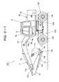
- FIG. 2-1 is a left side view of a wheel hydraulic excavator as a self-propelling working machine according to the second embodiment of the present invention.
- FIG. 2-2 is a hydraulic circuit diagram showing in a simplified form a hydraulic drive system arranged in the wheel hydraulic excavator illustrated in FIG. 2-1 .
- FIG. 2-3 is a flow chart illustrating a flow of processing to be performed at a controller shown in FIG. 2-2 .
- FIG. 2-4 is a perspective view of the inside of an operator's cab of the wheel hydraulic excavator illustrated in FIG. 2-1 , as viewed from front of and obliquely above an operator's seat.
- like elements and signals to the corresponding ones illustrated in FIGS. 1-1 and 1-2 are designated using like reference signs.
- a wheel hydraulic excavator 101 (hereinafter called “the hydraulic excavator 101") shown in FIG. 2-1 has a travel base 102.
- This travel base 102 has a pair of front wheels 103 and a pair of rear wheels 104, and travels by driving both the front wheels 103 and rear wheels 104.
- a travel hydraulic actuator as a drive source for the traveling is a travel motor 105 (hydraulic motor).
- the travel motor 105 is driven by the delivery oil fed from the main pump 22.
- a travel motor control valve 121 and a counterbalance valve 122 Interposed between the main pump 22 and the travel motor 105 are a travel motor control valve 121 and a counterbalance valve 122.
- the travel motor control valve 121 controls the flow rate and direction of pressure oil to be fed from the main pump 22 to the travel motor 105.
- An output shaft of the travel motor 105 is arranged to transmit an output torque from a transmission 123 to both the front wheels 103 and rear wheels 104 via propeller shafts and axles.
- the propeller shaft and axle to transmit the output torque to the front wheels 103 and the propeller shaft and axle to transmit the output torque to the rear wheels 104 are simplified, and are collectively illustrated as the propeller shaft 124 and axle 125.
- Valve positions of the travel motor control valve 121 are set at three positions, which are a forward-side position 121a where the direction of a flow of pressure oil to be fed to the travel motor 105 is controlled to a direction corresponding to a forward travel of the hydraulic excavator 101, a reverse-side position 121b where the direction of a flow of pressure oil to be fed to the travel motor 105 is controlled to a direction corresponding to a rearward travel of the hydraulic excavator 101, and a neutral position 121c where the feeding of pressure oil to the travel motor 105 is stopped.
- the travel motor control valve 121 is hydraulically piloted, and by a pedal-operated pilot valve 126,a pilot pressure to be applied to this travel motor control valve 121 is produced using the delivery pressure of the pilot pump 28 as a primary pressure.
- An operation pedal specifically an accelerator pedal 126 a of the pilot valve 126 is arranged on the floor 47 at a location laterally rightward of a steering column 130 as depicted in FIG. 2-4 .
- the pilot valve 126 is arranged corresponding to the travel motor 105, and is an actuation command means for producing a pilot pressure, as a command signal for the actuation of the travel motor 105, responsive to an operation of the accelerator pedal 126a.
- a slow-return valve 127 and directional control valve 128 are interposed between the pilot valve 126 and the travel motor control valve 121.
- the directional control valve 128 is operated by an F-N-R lever 129.
- Valve positions of the directional control valve 128 are set at three positions, which are a forward-side position 128a where a pilot pressure is guide in a direction to switch the travel motor control valve 121 to a forward-side position, a reverse-side position 128b where a pilot pressure is guided in a direction to switch the travel motor control valve 121 to a reverse-side position, and a neutral position 128c where no pilot pressure is fed to the travel motor control valve 121.
- a forward-side position 128a where a pilot pressure is guide in a direction to switch the travel motor control valve 121 to a forward-side position
- a reverse-side position 128b where a pilot pressure is guided in a direction to switch the travel motor control valve 121 to a reverse-side position
- the F-N-R lever 129 is arranged projecting laterally leftward from the left side wall of the steering column 130. It is to be noted that the hydraulic excavator 101 is provided with the F-N-R lever 129, steering wheel 134 and accelerator pedal 126a in place of the left travel control lever 45 and right travel control lever 46 in the first embodiment.
- the transmission 123 has a planetary reduction gear mechanism, an L-side clutch 1231 arranged on the side of a sun gear in the planetary reduction gear mechanism, and an H-side clutch 123h arranged on the side of a ring gear in the planetary reduction gear mechanism, and makes it possible to select the gear ratio from two levels consisting of "low gear” capable of producing low-speed/high-torque and "high gear” capable of producing high-speed/low-torque.
- the gear ratio of the "low gear” is set greater than that of the "high gear” .
- the L-side clutch 1231 and H-side clutch 123h are so-called negative clutches, each of which has a cylinder with a built-in spring, is biased by the spring in a connected state, and is brought into a released state when fed with pressure oil against the spring.
- Pressure oil to be fed to each of the cylinder of the L-side clutch 1231 and the cylinder of the H-side clutch 123h is controlled by a directional solenoid valve 131.
- the directional solenoid valve 131 is switched to an L-side position 131a when a control signal Clo is applied to a solenoid, and is switched to an H-side position 131b when a control signal Ch is applied to the solenoid.
- the directional solenoid valve 131 is switched to a locked position 131c.
- the transmission 123 functions as a travel-operation invalidating means to create a travel-operation invalidated state in which the hydraulic excavator 101 does not travel even when the pilot valve 126 as an actuation command means corresponding to the travel motor 105 (travel hydraulic actuator) is operated.
- This function is used as a parking brake.
- numeral 160 indicates a controller, which is provided with CPU, ROM, RAM and the like and operates in accordance with a computer program.
- This controller 160 is arranged in the operator's cab 9 of the hydraulic excavator 101.
- a low-gear command signal Slo or a high-gear command signal Sh is inputted from a shift switch 165.
- the shift switch 165 can be selectively held in a state, in which the low-gear command signal Slo is outputted, or in another state, in which the high-gear command signal Sh is outputted.
- the controller 160 continues to apply the control signal Clo to the solenoid of the directional solenoid valve 131 in a state that the input of the low-gear command signal Slo is continuing.
- the controller 160 continues to apply the control signal Ch to the solenoid of the directional solenoid valve 131 in a state that the input of the high-gear command signal Sh is continuing.
- the controller 160 is connected with a park switch 166.
- this park switch 166 When this park switch 166 is in an operated state, the controller 160 is brought into a state in which neither of the control signals Clo,Ch are outputted.
- the park switch 166 When the park switch 166 is in a non-operated state, the controller 160 is brought into a state in which these control signals Clo,Ch can be outputted.
- the park switch 166 is arranged on an upper part of a right side wall of the steering column 130.
- a boosting on/off valve 161 of a similar construction as the boosting on/off valve 61 in the first embodiment is arranged.
- a pilot pressure to be applied to the boosting on/off valve 161 is produced by a boosting proportional solenoid valve 162.
- the opening degree of the boosting on/off valve 161 changes steplessly.
- This boosting on/off valve 161 is a boosting means for raising the delivery pressure of the main pump 22 by restricting the return line 132 downstream of all the boom cylinder control valve, arm cylinder control valve 27, bucket cylinder control valve and the swing motor when these control valves are all in the non-feed states.
- a pilot line 133 extends from the pilot pump 28. Through this pilot line 113, the delivery oil of the pilot pump 28 is distributed to respective ones of the arm control device 29, boom control device, bucket control device and swing control device, which correspond to respective ones of arm cylinder control valve 27, boom cylinder control valve, bucket cylinder control valve and swing motor control valve (exclusive of the travel motor control valve 121) .
- This pilot line 133 is provided with a gate lock on/off valve 151 .
- the gate lock on/off valve 151 is a work-operation invalidating means for creating, in a batch for all the control devices such as the arm control device 29 corresponding to the work hydraulic actuators such as the arm cylinder 17, work-operation invalidated states in which the work hydraulic actuators are not actuated even when the control devices corresponding to the work hydraulic actuators are operated. It is to be noted that to the travel motor control valve 121, the delivery oil of the pilot pump 28 is guided through another pilot line (not shown) which is not cut off by the gate lock on/off valve 151.
- the controller 160 is set to determine whether or not the state of an application of the lock detection signal S1 from a lock detection switch 152 and the operated state of the park switch 166 have been both detected. Therefore, the lock detection switch 152, park switch 166 and controller 160 make up a non-operated state detection means for detecting operated states of both the transmission (travel-operation invalidating means) and the gate lock on/off valve 151 (work-operation invalidating means) as non-operated states of all the travel motor 105, boom cylinder 16, arm cylinder 17, bucket cylinder 18 and swing motor.
- the controller 160 is set to operate according to steps S12 to S16 illustrated in FIG. 2-3 .
- the controller 60 determines as in the first embodiment whether or not the gate lock lever 150 is in the locked state and the hydraulic excavator 101 is in the proper attitude, and in addition to these determinations, also determines whether or not the operated state of the park switch 166 has been detected (step S12).
- step S2 When the three states consisting of the locked state of the gate lock lever 150, the proper attitude and the operated state of the park switch 166 have been detected by the determinations in step S2 (YES in step S2), the controller 160, as in the first embodiment, outputs the control signals Cp,Cf to make the forced regeneration means (the boosting proportional solenoid valve 162, boosting on/off valve 161, flow-rate controlling, proportional solenoid valve 64 and regulator 63) initiate forced regeneration (step S13). No forced regeneration is initiated unless all the three states consisting of the locked state of the gate lock lever 150, the proper attitude and the operated state of the park switch 166 have been detected (NO in step S12).
- the forced regeneration means the boosting proportional solenoid valve 162, boosting on/off valve 161, flow-rate controlling, proportional solenoid valve 64 and regulator 63
- the controller 160 counts an elapsed time from the time point of the initiation of the output of the control signals Cp,Cf, and continues the output of the control signals Cp,Cf until elapse of a predetermined time as long as the detected state of all the three states consisting of the locked state of the gate lock lever 150, the proper attitude and the operated state of the park switch 166 continues.
- the continuous output time of the control signals Cp,Cf has passed the predetermined time (YES in step S14)
- the output of these control signals Cp,Cf is stopped to end the forced regeneration (step S15).
- the predetermined time is set as a time sufficient to remove particulate matter from the filter of the exhaust gas purification device 25.
- step S14 When any one of the three states has become no longer detected before the elapse of the predetermined time (NO in step S14), on the other hand, the controller 160 stops the output of the control signals Cp,Cf at this time point, and stops the forced regeneration (step S16) .
- the hydraulic drive system 120 With the hydraulic drive system 120, no forced regeneration is conducted, as in the hydraulic drive system 20 according to the first embodiment, unless all the work hydraulic actuators and travel hydraulic actuators are in non-operated states, and in addition, the proper attitude, including that both the arm cylinder 17 and bucket cylinder 18 as the specific cylinders out of the work hydraulic actuators are in the stroke-end states on the extended sides, has been detected. Forced regeneration can, therefore, be conducted while preventing false operations of the arm cylinder 17 and bucket cylinder 18. Accordingly, the hydraulic drive system 120 can provide the hydraulic excavator 101 with improved safety during forced regeneration.
- the proper attitude is set, as in the hydraulic drive system 20 according to the first embodiment, as the attitude that the bucket 15 has been folded toward the boom 13 as a result of the operations of both the arm cylinder 17 and bucket cylinder 18 to the stroke ends on the extend sides, and also as the attitude that the front working mechanism 12 is grounded.
- forced regeneration can be conducted in a state that the front working mechanism 12 is stabilized and hardly interferes with the surrounding.
- the hydraulic drive system 120 has, different from the hydraulic drive system 20 according to the first embodiment, the construction that cuts off by the gate lock on/off valve 151 the feeding of a pilot pressure as a primary pressure to the arm control device 29, boom control device, bucket control device and swing control device and also the construction that locks the transmission 123 to prevent rotation of the propeller shaft 124.
- these constructions can be adopted in wheel hydraulic excavators.
- wheel hydraulic excavators can be provided with improved safety during forced regeneration.
- the locked state of the gate lock lever 150 which operates the gate lock on/off valve 151 is detected by the lock detection switch 152. It is, therefore, possible to easily and collectively detect at one location that all the work hydraulic actuators (the boom cylinder 16, arm cylinder 17, bucket cylinder 18 and swing motor) are in non-operated states.
- the forced regeneration means is made up from the boosting proportional solenoid valve 162, boosting on/off valve 161,flow-rate controlling,proportional solenoid valve 64 and regulator 63.
- the forced regeneration means in the present invention is, however, not limited to such a construction. Depending on the capacity of the main pump 22, an engine output sufficient for forced regeneration can be obtained by simply raising the delivery pressure of the main pump 22. Therefore, the forced regeneration means may be constructed from the boosting proportional solenoid valve 162 and boosting on/off valve 161 only.
Landscapes
- Engineering & Computer Science (AREA)
- General Engineering & Computer Science (AREA)
- Mining & Mineral Resources (AREA)
- Civil Engineering (AREA)
- Structural Engineering (AREA)
- Mechanical Engineering (AREA)
- Chemical & Material Sciences (AREA)
- Fluid Mechanics (AREA)
- Combustion & Propulsion (AREA)
- Physics & Mathematics (AREA)
- Analytical Chemistry (AREA)
- Operation Control Of Excavators (AREA)
- Fluid-Pressure Circuits (AREA)
- Processes For Solid Components From Exhaust (AREA)
- Component Parts Of Construction Machinery (AREA)
- Control Of Vehicle Engines Or Engines For Specific Uses (AREA)
Abstract
Description
- The present invention relates to a hydraulic drive system for a working machine such as a hydraulic excavator. The hydraulic drive system can be adopted in the working machine, is provided with an exhaust gas purification device for capturing, by a filter, particulate matter in exhaust gas produced in an engine (prime mover), and burns off particulate matter deposited on the filter to conduct so-called forced regeneration.
- Conventionally, a hydraulic drive system for a working machine has been designed to permit detecting clogging of a filter in an exhaust gas purification device. When the working machine is in a non-operated state at the time of detection of clogging, the hydraulic drive system is set to automatically conduct forced regeneration. This forced regeneration conducted by the hydraulic drive system increases the delivery flow rate and delivery pressure of a hydraulic pump to increase the engine output, whereby the temperature of exhaust gas is raised. This increase in engine output leads to a rise in the temperature of exhaust gas. As a consequence, particulate matter with which the filter is clogged is burnt with the heat of the exhaust gas and is removed from the filter (see Patent Document 1).
-
- Patent Document 1:
JP-B-3073380 - In the above-described hydraulic drive system disclosed in
Patent Document 1, it is a condition for forced regeneration that the working machine is in a non-operated state. However, what attitude a working element of the working machine should take upon forced regeneration is not taken into consideration as a condition. In a hydraulic drive system, a hydraulic pump is in an operated state during operation of an engine. It is, therefore, necessary to keep in mind that, even in a non-operated state in which all hydraulic actuators for driving a working machine are not operated, an unforeseen situation may arise and pressure oil may be fed to one or more of the hydraulic actuators. Upon conducting forced regeneration in the course of operation of the engine, it is hence desired not only that the working machine is in a non-operated state but also that, even if pressure oil is fed to one or more the hydraulic actuators, the work element is in an undrivable attitude or is in a safe attitude even if driven. - With the foregoing circumstances in view, the present invention has as an object thereof the provision of a hydraulic drive system for a working machine, which can provide improved safety during forced regeneration.
- To achieve the above-described object, the present invention is constituted as will be described next.
- [1] The present invention is characterized in that in a hydraulic drive system for a working machine, said hydraulic drive system being provided with plural work hydraulic actuators for driving a work element constituting the working machine, a hydraulic pressure source for producing, by a hydraulic pump, pressure oil to be fed to the plural work hydraulic actuators, an engine as a drive source for the hydraulic pump, an exhaust gas purification device for capturing, by a filter, particulate matter in exhaust gas produced by the engine, a forced regeneration means for burning particulate matter deposited on the filter, and a control means for controlling the forced regeneration means, wherein the hydraulic drive system is further provided with a forced regeneration command means for commanding conduct of forced regeneration when operated, an attitude detection means for detecting a proper attitude specified beforehand as a safe attitude of the work element during forced regeneration, and a non-operated state detection means for detecting that all the hydraulic actuators for driving the working machine, said hydraulic actuators including the plural work hydraulic actuators, are in non-operated states; and taking as conditions for the conduct of forced regeneration that the non-operated states have been detected by the non-operated state detection means and the proper attitude has been detected by the attitude detection means, the control means makes the forced regeneration means conduct forced regeneration when the conduct of forced regeneration is commanded by the forced regeneration command means.
- In the present invention as described above in [1], it is set as conditions for conducting forced regeneration that non-operated states of all the work hydraulic actuators have been detected by the non-operated state detection means and the proper attitude of the work element has been detected by the attitude detection means. Unless the work element has taken the pre-specified proper attitude as its safe attitude during forced regeneration, it is thus possible to prevent conducting forced regeneration even when all the work hydraulic actuators are in non-operated states. Accordingly, the working machine can be provided with improved safety during forced regeneration.
- [2] The present invention may also be characterized in that in the invention as described above in [1], the plural work hydraulic actuators are single-rod hydraulic cylinders; control valves are arranged between the hydraulic pressure source and respective ones of the plural work hydraulic cylinders such that the control valves are switchable between feed states, in which pressure oil is fed from the hydraulic pressure source to the work hydraulic cylinders, and non-feed states, in which pressure oil is guided from the hydraulic pressure source to a hydraulic oil reservoir while cutting off flows of pressure oil from the hydraulic pressure source to the work hydraulic cylinders; the forced regeneration means has a boosting means capable of raising a delivery pressure of the hydraulic pump to a predetermined pressure by restricting lines downstream of all the control valves when all the control valves are in the non-feed states; and the attitude detection means detects, as an attribute of the proper attitude, that a specific cylinder out of the plural work hydraulic cylinders, said specific cylinder being drivable at the predetermined pressure, is in a stroke-end state on an extended side.
- In the present invention as described above in [2], the forced regeneration means raises the delivery pressure of the pump, that is, the pressure of the hydraulic pressure source to the predetermined pressure by the boosting means upon forced regeneration. At this time, the respective work hydraulic cylinders and the hydraulic pressure source have been cut off by the corresponding control valves. When the boosting means is actuated and the pressure in the hydraulic circuit rises to the predetermined pressure, however, a potential problem may arise in that the predetermined pressure may act on some or all of the work hydraulic actuators by a leakage.
- For example, a front working mechanism as a work element of a hydraulic excavator has a boom cylinder, arm cylinder and bucket cylinder as work hydraulic actuators formed of single-rod hydraulic cylinders. The boom cylinder is not actuated at the predetermined pressure required for forced regeneration, because the own weight of the front working mechanism always acts on the boom cylinder. However, the arm cylinder and bucket cylinder include those which may be driven at the predetermined pressure. These arm cylinder and bucket cylinder may each correspond to the specific cylinder in the present invention as described above in [2]. When both a rod chamber and a bottom chamber become equal in pressure to each other in a single-rod hydraulic cylinder, pressing force acts in an extending direction on a rod because a receiving surface in the bottom chamber is greater than that in the rod chamber. When the single-rod hydraulic cylinder is in the stroke-end state of the extended side, any further extension of the single-rod hydraulic cylinder is prevented so that the single-rod hydraulic cylinder is not actuated. Using the characteristics of this operation of the single-rod hydraulic cylinder in the present invention as described above in [2], no forced regeneration is conducted unless the attitude detection means has detected the stroke-end state of the specific cylinder on the extended side thereof. It is, therefore, possible to conduct forced regeneration while wiping out a possibility of false operation of the specific cylinder.
- [3] The present invention may also be characterized in that in the invention as described above in [1] or [2], the control means makes the forced regeneration means stop forced regeneration when the conditions have become no longer satisfied during the conduct of forced regeneration.
- [4] The present invention may also be characterized in that in the invention as described above in [1], the working machine is self-propelling, and has a travel hydraulic actuator as a drive source for self-traveling; actuation command means are arranged for the plural work hydraulic actuators and the travel hydraulic actuator, respectively, to produce command signals for the actuation of the respective hydraulic actuators depending on operations by corresponding parts of the body such as the hands and feet; an operation batch-invalidating means is arranged to create, in a batch for all the operation command means, operation-invalidated states in which neither the work hydraulic actuators are actuated even when the actuation command means corresponding to the work hydraulic actuators are operated nor the travel hydraulic actuator is actuated even when the actuation command means corresponding to the travel hydraulic actuator is operated; and the non-operated state detection means detects an actuated state of the operation batch-invalidating means as the non-operated states.
- The present invention as described above in [4] has the construction provided with the operation batch-invalidating means, and this construction is commonly adopted in crawler working machines such as crawler hydraulic excavators among self-propelling working machines of different kinds. According to the present invention as described above in [4], it is hence possible to provide a hydraulic drive system of a crawler working machine with improved safety during forced regeneration.
- [5] The present invention may also be characterized in that in the invention as described above in [1], the working machine is self-propelling, and has a travel hydraulic actuator as a drive source for self-traveling; actuation command means are arranged for the plural work hydraulic actuators and the travel hydraulic actuator, respectively, to produce command signals for the actuation of the respective hydraulic actuators depending on operations by corresponding parts of the body such as the hands and feet; a travel-operation invalidating means is arranged to create a travel-operation invalidated state in which the working machine does not travel even when the actuation command means corresponding to the travel hydraulic actuator is operated, and a work-operation invalidating means is also arranged to create a work-operation invalidated state in which the work hydraulic actuators are not actuated even when the actuation command means corresponding to the work hydraulic actuators are operated; and the non-operated state detection means detects as the non-operated states that the travel-operation invalidating means and work-operation invalidating means are both in operated states.
- The present invention as described above in [5] has the construction provided with the travel-operation invalidating means and work-operation invalidating means, and this construction is commonly adopted in wheel working machines such as wheel hydraulic excavators among self-propelling working machines of different kinds. According to the present invention as described above in [5], it is hence possible to provide a hydraulic drive system of a wheel working machine with improved safety during forced regeneration.
- [6] The present invention may also be characterized in that in the invention as described above in [1], the work element is a front working mechanism, and a grounded attitude of the front working mechanism is included as the attribute of the proper attitude.
- According to the present invention, it is possible, as mentioned above, to prevent conducting forced regeneration even when all the work hydraulic actuators are in non-operated states, unless the work element has taken the proper attitude pre-specified as a safe attitude during forced regeneration. Therefore, the present invention can provide the working machine with improved safety during forced regeneration.
-
- [
FIG. 1-1] FIG. 1-1 is a left side view of a crawler hydraulic excavator as a self-propelling working machine according to a first embodiment of the present invention. - [
FIG. 1-2] FIG. 1-2 is a hydraulic circuit diagram showing in a simplified form a hydraulic drive system arranged in the crawler hydraulic excavator shown inFIG. 1-1 . - [
FIG. 1-3] FIG. 1-3 is a flow chart illustrating a flow of processing to be performed at a controller depicted inFIG. 1-2 . - [
FIG. 1-4] FIG. 1-4 is a perspective view of the inside of an operator's cab of the crawler hydraulic excavator illustrated inFIG. 1-1 , as viewed from front of and obliquely above an operator's seat. - [
FIG. 2-1] FIG. 2-1 is a left sideviewof awheel hydraulic excavator as a self-propelling working machine according to a second embodiment of the present invention. - [
FIG. 2-2] FIG. 2-2 is a hydraulic circuit diagram showing in a simplified form a hydraulic drive system arranged in the wheel hydraulic excavator illustrated inFIG. 2-1 . - [
FIG. 2-3] FIG. 2-3 is a flow chart illustrating a flow of processing to be performed at a controller shown inFIG. 2-2 . - [
FIG. 2-4] FIG. 2-4 is a perspective view of the inside of an operator's cab of the wheel hydraulic excavator illustrated inFIG. 2-2 , as viewed from front of and obliquely above an operator's seat. - A description will be made about the first and second embodiments of the present invention.
- With reference to
FIGS. 1-1 through 1-4, a description will be made about the first embodiment.FIG. 1-1 is a left side view of a crawler hydraulic excavator as a self-propelling working machine according to the first embodiment of the present invention.FIG. 1-2 is a hydraulic circuit diagram showing in a simplified form a hydraulic drive system arranged in the crawler hydraulic excavator shown inFIG. 1-1 .FIG. 1-3 is a flow chart illustrating a flow of processing to be performed at a controller depicted inFIG. 1-2 .FIG. 1-4 is a perspective view of the inside of an operator's cab of the crawler hydraulic excavator illustrated inFIG. 1-1 , as viewed from front of and obliquely above an operator's seat. - As illustrated in
FIG. 1-1 , the crawler hydraulic excavator 1 (hereinafter simply called "thehydraulic excavator 1") is provided with atravel base 2 which runs by driving crawler tracks 3, a revolvingupperstructure 8 swingably connected to thetravel base 2, and afront working mechanism 12 substantially centrally arranged as a work element on a front section of the revolvingupperstructure 8. - A left side section of the
travel base 2 includes atrack frame 4 as a framework structure. On a rear end portion of thetrack frame 4, atravel motor 5 is mounted, as a travel hydraulic actuator, integrally with a reduction gear box. The reduction gear box is arranged to drive adrive wheel 6. A drivenwheel 7 is arranged on a front end portion of thetrack frame 4. The crawler track 3 is wrapped around thedrive wheel 6 and drivenwheel 7, and is located surrounding thetrack frame 4. By transmitting an output torque of thetravel motor 5 to the crawler track 3 via the reduction gear box and drivewheel 6, the crawler track 3 is driven around thetrack frame 4, and as a result, the crawlerhydraulic excavator 1 travels. Similar to the left side section of thetravel base 2, its right side section also has a construction provided with a track frame, travel motor (travel hydraulic actuator), drive wheel, driven wheel and crawler track. - On a left front section of the revolving
upperstructure 8, an operator'scab 9 is mounted. Disposed behind the operator'scab 9 is anengine compartment 10, in which an engine 23 (diesel engine), main pump 22 (variable displacement hydraulic pump), and the like of ahydraulic drive system 20 to be mentioned subsequently herein are accommodated. From a top part of theengine compartment 10, anoutlet pipe 26 extends to guide exhaust gas from theengine 23 outward of thehydraulic excavator 1. - The
front working mechanism 12 is provided with aboom 13. Theboom 13 of thefront working mechanism 12 is pivotally connected at one end thereof via a pin to a foot part arranged in a front section of aframe 11 that constitutes the revolvingupperstructure 8. To the opposite end of theboom 13, anarm 14 is pivotally connected at one end thereof via a pin. To the opposite end of thearm 14, abucket 15 is pivotally connected at one end thereof via a pin. InFIG. 1-1 ,sign 12a indicates a pin joint at the other end of theboom 13 and the one end of thearm 14, andsign 12b designates a pin joint at the other end of thearm 14 and the one end of thebucket 15. Theboom 13 is drivable by a boom cylinder 16 (single-rod hydraulic cylinder) as a work hydraulic actuator. Thisboom cylinder 16 is pivotally connected at a bottom-side end of acylinder tube 16a to the hoot part via a pin, and is also pivotally connected at an end of arod 16b to an intermediate part of theboom 8 via a pin. Thearm 14 is drivable by an arm cylinder 17 (single-rod hydraulic cylinder) as a work hydraulic actuator. Thisarm cylinder 17 is pivotally connected at a bottom-side end of acylinder tube 17a to theboom 13 via a pin, and is also pivotally connected at an end of arod 17b to the one end of thearm 14 via a pin. Thebucket 15 is arranged such that an extending/retracting motion of a bucket cylinder 18 (single-rod hydraulic cylinder) as a work hydraulic actuator is transmitted via alink mechanism 18c to drive thebucket 15. Thisbucket cylinder 18 is pivotally connected at a bottom-side end of acylinder tube 18a to thearm 14 via a pin, and is also pivotally connected at an end of arod 18b to thelink mechanism 18c via a pin. - As depicted in
FIG. 1-2 , thehydraulic drive system 20 according to the first embodiment is provided with theleft travel motor 5 and right travel motor (not shown) as travel hydraulic actuators which are a drive source for self-propelling of thehydraulic excavator 1, a swing motor (unillustrated hydraulic motor) as a work hydraulic actuator which is a drive source for the revolvingupperstructure 8, theboom cylinder 16,arm cylinder 17 andbucket cylinder 18 as plural work hydraulic actuators for driving thefront working mechanism 12.FIG. 1-2 depicts only thearm cylinder 17 and the remainingboom cylinder 16 andbucket cylinder 18 are omitted. - A hydraulic pressure source for a drive pressure, which drives these
left travel motor 5, right travel motor, swing motor,boom cylinder 16,arm cylinder 17 andbucket cylinder 18, is themain pump 22. A drive source for thismain pump 22 is theengine 23. Anexhaust gas pipe 24 extends from theengine 23, and thisexhaust gas pipe 24 is provided with an exhaustgas purification device 25. The exhaustgas purification device 25 serves to capture, by a filter, particulate matter in exhaust gas produced by theengine 23. From the exhaustgas purification device 25, the above-describedoutlet pipe 26 extends. - Between the
main pump 22 and respective ones of theleft travel motor 5, right travel motor, swing motor,boom cylinder 16,arm cylinder 17 andbucket cylinder 18, actuator control valves are interposed to control the flows of pressure oil to be fed from themain pump 22.FIG. 1-2 depicts, as a representative of these actuator control valves, only an armcylinder control valve 27 interposed between themain pump 22 and thearm cylinder 17. This armcylinder control valve 27 is a hydraulically-piloted, spring-centered, 3-position valve. Valve positions of the armcylinder control valve 27 are set at aninitial position 27a (neutral position),first operating position 27b andsecond operating position 27c. Theinitial position 27a (neutral position) is a valve position, in which a passage is formed to guide the delivery oil of themain pump 22 to ahydraulic oil reservoir 21 while cutting off a flow of pressure oil from themain pump 22 to either a bottom chamber 17a1 or a rod chamber 17a2 of thearm cylinder 17, in other words, is a valve position in which the armcylinder control valve 27 is brought into a non-feed state. Thefirst operating position 27b is a valve position, in which two passages are formed, one being a passage that guides the delivery oil of themain pump 22 to the bottom chamber 17a1 of thearm cylinder 17, and the other a passage that guides pressure oil, which is contained in the rod chamber 17a2, to thehydraulic oil reservoir 21, in other words, is a valve position in which the armcylinder control valve 27 is brought into a first feed state to extend thearm cylinder 17. Thesecond operating position 27c is a valve position, in which two passages are formed, one being a passage that guides the delivery oil of themain pump 22 to the rod chamber 17a2 of thearm cylinder 17, and the other a passage that guides pressure oil, which is contained in the bottom chamber 17a1, to thehydraulic oil reservoir 21, in other words, is a valve position in which the armcylinder control valve 27 is brought into a second feed state to contract thearm cylinder 17. - The boom cylinder control valve and bucket cylinder control valve are of a similar construction as the arm
cylinder control valve 27, the boom cylinder control valve is switchable to a non-feed state, first feed state or second feed-state with respect to theboom cylinder 16, and the bucket cylinder control valve is switchable to a non-feed state, first feed state or second feed-state with respect to thebucket cylinder 18. - The left travel motor control valve, right travel motor control valve and swing motor control valve are of a similar construction as the arm
cylinder control valve 27. In an initial position (neutral position), however, a passage is formed to guide the delivery oil of themain pump 22 to thehydraulic oil reservoir 21 while cutting off a flow of pressure oil from themain pump 22 to any of the two inlet/outlet ports of a hydraulic motor as the travel motor or swing motor. In a first operating position, two passages are formed, one being a passage that guides the delivery oil of themain pump 22 to one of the inlet/outlet ports of the hydraulic motor, and the other a passage that guides pressure oil, which has been discharged from the other one of the inlet/outlet ports, to thehydraulic oil reservoir 21. In a second operating position, two passages are formed, one being a passage that guides the delivery oil of themain pump 22 to the other one of the inlet/outlet ports of the hydraulic motor, and the other a passage that guides pressure oil, which has been discharged from the one of the inlet/outlet ports of the hydraulic motor, to thehydraulic oil reservoir 21. The corresponding relations between the respective ones of the initial position, first operation position and second operating position and the respective ones of the non-feed state, first feed state and second feed state are similar to those in the armcylinder control valve 27. - Using the delivery pressure of a pilot pump 28 (fixed displacement hydraulic pump) as a primary pressure, a pilot pressure to be applied to the arm
cylinder control valve 27 is produced by anarm control device 29. Designated atnumeral 30 is a left travel control device, which by using the delivery pressure of thepilot pump 28 as a primary pressure, produces a pilot pressure to be applied to the travel motor control valve arranged corresponding to theleft travel motor 5. Indicated atnumeral 31 is a right travel control device, which by using the delivery pressure of thepilot pump 28 as a primary pressure, produces a pilot pressure to be applied to the travel motor control valve arranged corresponding to the right travel motor. A pilot pressure to be applied to the boom cylinder control valve, a pilot pressure to be applied to the bucket cylinder control valve and a pilot pressure to be applied to the swing motor control valve are produced by a boom control device, bucket control device and swing control device of a similar construction as thearm control device 29, respectively, by using the delivery pressure of thepilot pump 28 as a primary pressure. These boom cylinder control valve, bucket cylinder control valve, swing motor control valve, boom control device, bucket control device and swing control device are omitted inFIG. 1-2 . Thearm control device 29, lefttravel control device 30, righttravel control device 31, boom control device, bucket control device and swing control device are independently arranged in association with thearm cylinder 17, lefttravel motor 5, right travel motor,boom cylinder 16,bucket cylinder 18 and swing motor, respectively, and are actuation command means for producing pilot pressures as command signals for the actuation of the respective hydraulic actuators when operated by corresponding parts of the body such as the hands and feet. - As depicted in
FIG. 1-4 , aconsole 41 arranged laterally leftward of an operator'sseat 40 is provided with a swing/arm control lever 43 which is tiltingly operated by the left hand. This swing/arm control lever 43 is shared by the swing control device andarm control device 29. The swing control device produces a pilot pressure responsive to a tilting operation of the swing/arm control lever 43 in a forward-to-rear direction, and thearm control device 29 produces a pilot pressure responsive to a tilting operation of the swing/arm control lever 43 in a left-to-right direction. Aconsole 42 arranged laterally rightward of the operator'sseat 40 is provided with a boom/bucket control lever 44 which is tiltingly operated by the right hand. This boom/bucket control lever 44 is shared by the boom control device and bucket control device. The boom control device produces a pilot pressure responsive to a tilting operation of the boom/bucket control lever 44 in the forward-to-rear direction, and the bucket control device produces a pilot pressure responsive to a tilting operation of the boom/bucket control lever 44 in the left-to-right direction. - From a
floor 47 forward of the operator'sseat 40, a lefttravel control lever 45 of the lefttravel control device 30 and a righttravel control lever 46 of the righttravel control device 31 extend upward side by side in lateral direction. Acontrol pedal 45a is arranged integrally with a basal end portion of the lefttravel control lever 45, so that the lefttravel control lever 45 can be operated by either the hand or the foot. Likewise, acontrol pedal 46a is arranged integrally with a basal end portion of the righttravel control lever 46. Concerning the lefttravel control lever 45 and the righttravel control lever 46, tilting operations in the forward direction are operations that command a forward travel, tilting operations in the rearward direction are operations that command a rearward travel, tilt amounts are operations that command travel speeds, and tilting operation strokes with a difference set therebetween are operations that command a steering. - As shown in
FIG. 1-2 , apilot line 34 extends from thepilot pump 28. Through thispilot line 34, the delivery oil of thepilot pump 28 is distributed to all the control devices such as the above-mentionedarm control device 29. Thispilot line 34 is provided with a gate lock on/offvalve 51 which can collectively cut off the primary pressure to all the control devices. This gate lock on/offvalve 51 is an operation batch-invalidating means for creating, in a batch for all the control devices, operation-invalidated states in which neither the work hydraulic actuators such as thearm cylinder 17 are actuated even when the control devices such as thearm control device 29 corresponding to the work hydraulic actuators are operated nor the travel hydraulic motors such as thetravel motor 5 are actuated even when the lefttravel control device 30 and the like corresponding to the travel hydraulic actuators are operated. - The gate lock on/off
valve 51 is a lever-operated, spring return valve, and is operated by agate lock lever 50. In this gate lock on/offvalve 51, an initial position corresponds to anopen position 51a, and an operating position corresponds to aclosed position 51b. In theclosed position 51b of the gate lock on/offvalve 51, thepilot line 34 is closed to collectively cut off the primary pressure to all the control devices such as thearm control device 29. Thegate lock lever 50 can be selectively held by an unillustrated construction in a locked position corresponding to the valve position of the gate lock on/offvalve 51 or in a canceled position corresponding to the open position of the gate lock on/offvalve 51. As depicted inFIG. 1-4 , thegate lock lever 50 is arranged laterally leftward of theleft console 41, that is, between theconsole 41 and adoor 9a (seeFIG. 1-1 ). - Attached to the
gate lock lever 50 is alock detection switch 52, which detects that thegate lock lever 50 is in a locked position, in other words, in a locked state, and outputs a lock detection signal S1 (electrical signal). The lock detection signal S1 is inputted to acontroller 60. - On the pin joint 12a for the
boom 13 andarm 14, anarm angle sensor 53 is arranged to output an arm angle detection signal Sa (electrical signal) corresponding to an angle of thearm 14 relative to theboom 13. On the pin joint 12b for thearm 14 and thebucket 15, abucket angle sensor 54 is arranged to output a bucket angle detection signal Sb (electrical signal) corresponding to an angle of thebucket 15 relative to thearm 14. The arm angle detection signal Sa and bucket angle detection signal Sb are also inputted to thecontroller 60. - The
cylinder tube 16a of theboom cylinder 16 is provided with aboom pressure sensor 55, which outputs a boompressure detection signal Spb (electrical signal) corresponding to a pressure inside the bottom chamber of theboom cylinder 16. This boom pressure detection signal Spb is also inputted to thecontroller 60. - A
main line 32, which guides a delivery pressure from themain pump 22 to parallel circuits, is provided with a delivery pressure sensor 56, which outputs a delivery pressure detection signal Spp (electrical signal) corresponding to the delivery pressure of themain pump 22. This delivery pressure detection signal Spp is also inputted to thecontroller 60. - The above-described plural actuator control valves such as the arm
cylinder control valve 27 form the parallel circuits between themselves and themain pump 22. Areturn line 33, which extends from the parallel circuits to thehydraulic oil reservoir 21, is provided with a boosting on/offvalve 61 capable of opening or closing thereturn line 33. This boosting on/offvalve 61 is a hydraulically-piloted valve. By a boostingproportional solenoid valve 62, a pilot pressure to be applied to this boosting on/offvalve 61 is produced using the delivery pressure of thepilot pump 28 as a primary pressure. The opening degree of the boosting on/offsolenoid valve 61 changes steplessly, as its valve element displaces between an open position 61a (initial position) and a closed position 61b (operating position) depending on the level of the pilot pressure. This boosting on/offvalve 61 is a boosting means for raising the delivery pressure of themain pump 22 by restricting lines downstream of all the actuator control valves (the boom cylinder control valve, armcylinder control valve 27, bucket cylinder control valve, swing motor, left travel motor control valve and right travel motor control valve) when all the actuator control valves are in the non-feed states. - The displacement of the
main pump 22 is controlled by a hydraulically-pilotedregulator 63. Byaflow-rate controlling,proportional solenoid valve 64, a pilot pressure to be applied to thisregulator 63 is produced using the delivery pressure of thepilot pump 28 as a primary pressure. The displacement changes steplessly depending on the level of the pilot pressure. - By increasing the delivery flow rate of the
main pump 22 via the flow-rate controlling,proportional solenoid valve 64 andregulator 63 in parallel with raising the delivery pressure of themain pump 22 via the boostingproportional solenoid valve 62 and boosting on/offvalve 61, the engine output increases. As a result, it is possible to obtain an exhaust gas temperature required for forced regeneration that burns particulate matter deposited on the filter of the exhaust gas purification device. Therefore, the boosting on/offvalve 61, boostingproportional solenoid valve 62, flow-rate controlling,proportional solenoid valve 64 andregulator 63 makes up a forced regeneration means for increasing the output of theengine 23 to raise the temperature of exhaust gas, and hence, burning particulate matter deposited on the filter of the exhaustgas purification device 25 with the heat of the temperature-raised exhaust gas. - As a forced regeneration command means for commanding the conduct of forced regeneration when operated by a part of the body, a forced
regeneration switch 65 is arranged. This forcedregeneration switch 65 is arranged in the operator'scab 9, although it is not depicted inFIG. 1-4 . This forcedregeneration switch 65 is a spring-return, push-button switch. A forced regeneration command signal So corresponding to an operated state of the forcedregeneration switch 65 is inputted to thecontroller 60. - The
controller 60 is arranged on a body of thehydraulic excavator 1, for example, in the operator'scab 9. Thecontroller 60 is a unit, which is provided with CPU, ROM, RAM and the like and is operated in accordance with a computer program. Thiscontroller 60 is set to determine whether or not the lock detection signal S1 has been fed from thelock detection switch 52. Therefore, thelock detection switch 52 andcontroller 60 make up a non-operated state detection means for detecting an operated state of the gate lock on/off valve 51 (operation batch-invalidating means), that is, a non-operated state in which no drive pressure oil is fed to any of theleft travel motor 5, right travel motor,boom cylinder 16,arm cylinder 17, bucket cylinder and swing motor. - Further, the
controller 60 is set to control the boostingproportional solenoid valve 62 and flow-rate controlling,proportional solenoid valve 64. Therefore, thecontroller 60 is a control means for controlling the forced regeneration means. - The
controller 60 is set to operate according to steps S1 to S6 illustrated inFIG. 1-3 . Thecontroller 60 is actuated in association with a stat-up of theengine 23. When the forced regeneration command signal So is inputted from the forcedregeneration switch 65 after the start-up (YES in step S1), thecontroller 60 determines whether or not the input of the lock detection signal S1 from thelock detection switch 52 is continuing, namely, whether or not thegate lock lever 50 is in the locked state. - In parallel with this determination, the
controller 60 also determines whether or not the arm angle signal Sa from thearm angle sensor 53 is equal to the angle corresponding to the stroke end of thearm cylinder 17 on its extended side, the bucket angle signal Sb from thebucket angle sensor 54 is equal to the angle corresponding to the stroke end of thebucket cylinder 18 on its extended side, and the boom pressure signal Spb from theboom pressure sensor 55 indicates a negative pressure, in other words, whether or not thefront working mechanism 12 is in the proper attitude. As illustrated inFIG. 1-1 , this proper attitude corresponds to an attitude that thebucket 15 has been folded toward theboom 13 as a result of the operations of both thearm cylinder 17 andbucket cylinder 18 to the stroke ends on the extend sides, and also corresponds to an attitude that thefront working mechanism 12 is grounded (the attitude that the pressure of the bottom chamber 17a1 of theboom cylinder 16 has become a negative pressure). This proper attitude has been set beforehand as a safe attitude of thefront working mechanism 12 upon conducting forced regeneration. Therefore, thearm angle sensor 53,bucket angle sensor 54,boomangle sensor 55 andcontroller 60 make up an attitude detection means for detecting a proper attitude specified beforehand as a safe attitude of the front working mechanism 12 (work element) during forced regeneration. - When the locked state of the
gate lock lever 50 and the proper attitude are both detected by the determinations in step S2 (YES in step S2), thecontroller 60 makes the forced regeneration means (the boostingproportional solenoid valve 62, boosting on/offvalve 61, flow-rate controlling,proportional solenoid valve 64 and regulator 63) initiate forced regeneration (step S3). In other words, preset control signals Cp,Cf are outputted to the boostingproportional solenoid valve 62 and flow-rate controlling,proportional solenoid valve 63, respectively. No forced regeneration is initiated unless the locked state of thegate lock lever 50 and the proper attitude have been both detected (NO in step S2). - The boosting
proportional solenoid valve 62 to which the control signal Cp has been applied produces a pilot pressure, and this pilot pressure actuates the boosting on/offvalve 61 toward the closed position, whereby the delivery pressure of themain pump 22 increases. The flow-rate controlling,proportional solenoid valve 64 to which the control signal Cf has been applied produces a pilot pressure, and this pilot pressure actuates theregulator 63 in the direction that the displacement is increased, whereby the delivery flow rate of themain pump 22 increases. - The
engine 23 is set to be controlled in an idling state for energy saving and noise reduction in the locked state of thegate lock lever 50. However, theengine 23 is controlled to increase its output in association with a rise in the delivery pressure of themain pump 22 and an increase in its delivery flow rate . As a result of an increase in the output of theengine 23, the temperature of exhaust gas rises so that particulate matter burns with the heat of the exhaust gas, in other words, forced regeneration is conducted. During the forced regeneration, thecontroller 60 performs adjustments of the control signal Cp based on the delivery pressure indicated by the delivery pressure detection signal Spp to stabilize the delivery pressure of themain pump 22 at a predetermined pressure needed for the forced regeneration. - The
controller 60 counts an elapsed time from the time point of the initiation of the output of the control signals Cp,Cf, and continues the output of the control signals Cp,Cf until elapse of a predetermined time as long as the detected state of both the locked state of thegate lock lever 50 and the proper attitude continues . When the continuous output time of the control signals Cp,Cf has passed the predetermined time (YES in step S4), the output of these control signals Cp, Cf is stopped to end the forced regeneration (step S5). It is to be noted that the predetermined time is set as a time sufficient to remove particulate matter from the filter of the exhaustgas purification device 25. - When both the locked state of the
gate lock lever 50 and the proper attitude have become no longer detected before the elapse of the predetermined time (NO in step S4), on the other hand, thecontroller 60 stops the output of the control signals Cp,Cf at this time point, and stops the forced regeneration (step S6). - According to the
hydraulic drive system 20 of the first embodiment, the following advantageous effects can be brought about. - With the
hydraulic drive system 20, the delivery pressure of themain pump 22 is caused to rise to the predetermined pressure by the boosting on/offvalve 61 upon conducting forced regeneration. At this time, thearm cylinder 17 andmain pump 22 are cut off from each other, and so thebucket cylinder 18 andmain pump 22. Nonetheless, there is a possibility that the predetermined pressure may act on either one or both of thearm cylinder 17 andbucket cylinder 18 by a leakage. Thearm cylinder 17 and/orbucket cylinder 18 may be driven as a result of the application of the predetermined pressure. According to thehydraulic drive system 20, however, forced regeneration is not conducted unless not only the non-operated states of all the work hydraulic actuators and travel hydraulic actuator but also the proper attitude, which includes that both thearm cylinder 17 andbucket cylinder 18 as specific cylinders out of the work hydraulic actuators are in the stroke end states on their extended sides, are detected. Forced regeneration can, therefore, be conducted while avoiding false operations of thearm cylinder 17 andbucket cylinder 18. Accordingly, thehydraulic drive system 20 can provide thehydraulic excavator 1 with improved safety during forced regeneration. - In the
hydraulic drive system 20, the proper attitude corresponds to the attitude that thebucket 15 has been folded toward theboom 13 as a result of the operations of both thearm cylinder 17 andbucket cylinder 18 to the stroke ends on the extend sides, and also corresponds to an attitude that thefront working mechanism 12 is grounded. As a consequence, forced regeneration can be conducted in a state that thefront working mechanism 12 is stabilized and hardly interferes with the surrounding. - According to the
hydraulic drive system 20, the locked state of thegate lock lever 50 which operates the gate lock on/offvalve 51 is detected by thelock detection switch 52. It is, therefore, possible to easily and collectively detect at one location that all the hydraulic actuators (theleft travel motor 5, right travel motor,boom cylinder 16,arm cylinder 17,bucket cylinder 18 and swing motor) of thehydraulic excavator 1 are in non-operated states. - The
hydraulic drive system 20 is constructed to cut off the feeding of a primary pressure to all the control devices such as thearm control device 29 by the gate lock on/offvalve 51. This construction is commonly adopted in crawler hydraulic excavators. Therefore, thehydraulic drive system 20 makes it possible to provide a crawler hydraulic excavator with improved safety during forced regeneration. - In the above-described first embodiment, the forced regeneration means is constructed from the boosting
proportional solenoid valve 62, boosting on/offvalve 61, flow-rate controlling,proportional solenoid valve 64 andregulator 63. The forced regeneration means in the present invention is, however, not limited to such a construction. The forced regeneration means may be constructed from the boostingproportional solenoid valve 62 and boosting on/offvalve 61 only, because depending on the capacity of themain pump 22, an engine output sufficient for forced regeneration can be obtained by simply raising the delivery pressure of themain pump 22. - With reference to
FIGS. 2-1 through 2-4, a description will be made about the second embodiment.FIG. 2-1 is a left side view of a wheel hydraulic excavator as a self-propelling working machine according to the second embodiment of the present invention.FIG. 2-2 is a hydraulic circuit diagram showing in a simplified form a hydraulic drive system arranged in the wheel hydraulic excavator illustrated inFIG. 2-1 .FIG. 2-3 is a flow chart illustrating a flow of processing to be performed at a controller shown inFIG. 2-2 .FIG. 2-4 is a perspective view of the inside of an operator's cab of the wheel hydraulic excavator illustrated inFIG. 2-1 , as viewed from front of and obliquely above an operator's seat. Among elements and signals illustrated inFIGS. 2-1 through 2-4, like elements and signals to the corresponding ones illustrated inFIGS. 1-1 and1-2 are designated using like reference signs. - A wheel hydraulic excavator 101 (hereinafter called "the
hydraulic excavator 101") shown inFIG. 2-1 has atravel base 102. Thistravel base 102 has a pair offront wheels 103 and a pair ofrear wheels 104, and travels by driving both thefront wheels 103 andrear wheels 104. A travel hydraulic actuator as a drive source for the traveling is a travel motor 105 (hydraulic motor). Thetravel motor 105 is driven by the delivery oil fed from themain pump 22. Interposed between themain pump 22 and thetravel motor 105 are a travelmotor control valve 121 and acounterbalance valve 122. The travelmotor control valve 121 controls the flow rate and direction of pressure oil to be fed from themain pump 22 to thetravel motor 105. An output shaft of thetravel motor 105 is arranged to transmit an output torque from atransmission 123 to both thefront wheels 103 andrear wheels 104 via propeller shafts and axles. InFIG. 2-2 , the propeller shaft and axle to transmit the output torque to thefront wheels 103 and the propeller shaft and axle to transmit the output torque to therear wheels 104 are simplified, and are collectively illustrated as thepropeller shaft 124 andaxle 125. - Valve positions of the travel
motor control valve 121 are set at three positions, which are a forward-side position 121a where the direction of a flow of pressure oil to be fed to thetravel motor 105 is controlled to a direction corresponding to a forward travel of thehydraulic excavator 101, a reverse-side position 121b where the direction of a flow of pressure oil to be fed to thetravel motor 105 is controlled to a direction corresponding to a rearward travel of thehydraulic excavator 101, and aneutral position 121c where the feeding of pressure oil to thetravel motor 105 is stopped. - The travel
motor control valve 121 is hydraulically piloted, and by a pedal-operatedpilot valve 126,a pilot pressure to be applied to this travelmotor control valve 121 is produced using the delivery pressure of thepilot pump 28 as a primary pressure. An operation pedal, specifically anaccelerator pedal 126 a of thepilot valve 126 is arranged on thefloor 47 at a location laterally rightward of asteering column 130 as depicted inFIG. 2-4 . Thepilot valve 126 is arranged corresponding to thetravel motor 105, and is an actuation command means for producing a pilot pressure, as a command signal for the actuation of thetravel motor 105, responsive to an operation of theaccelerator pedal 126a. - As shown in
FIG. 2-2 , a slow-return valve 127 anddirectional control valve 128 are interposed between thepilot valve 126 and the travelmotor control valve 121. Thedirectional control valve 128 is operated by anF-N-R lever 129. Valve positions of thedirectional control valve 128 are set at three positions, which are a forward-side position 128a where a pilot pressure is guide in a direction to switch the travelmotor control valve 121 to a forward-side position, a reverse-side position 128b where a pilot pressure is guided in a direction to switch the travelmotor control valve 121 to a reverse-side position, and aneutral position 128c where no pilot pressure is fed to the travelmotor control valve 121. As depicted inFIG. 2-4 , theF-N-R lever 129 is arranged projecting laterally leftward from the left side wall of thesteering column 130. It is to be noted that thehydraulic excavator 101 is provided with theF-N-R lever 129,steering wheel 134 andaccelerator pedal 126a in place of the lefttravel control lever 45 and righttravel control lever 46 in the first embodiment. - The
transmission 123 has a planetary reduction gear mechanism, an L-side clutch 1231 arranged on the side of a sun gear in the planetary reduction gear mechanism, and an H-side clutch 123h arranged on the side of a ring gear in the planetary reduction gear mechanism, and makes it possible to select the gear ratio from two levels consisting of "low gear" capable of producing low-speed/high-torque and "high gear" capable of producing high-speed/low-torque. The gear ratio of the "low gear" is set greater than that of the "high gear" . The L-side clutch 1231 and H-side clutch 123h are so-called negative clutches, each of which has a cylinder with a built-in spring, is biased by the spring in a connected state, and is brought into a released state when fed with pressure oil against the spring. - Pressure oil to be fed to each of the cylinder of the L-side clutch 1231 and the cylinder of the H-side clutch 123h is controlled by a
directional solenoid valve 131. Thedirectional solenoid valve 131 is switched to an L-side position 131a when a control signal Clo is applied to a solenoid, and is switched to an H-side position 131b when a control signal Ch is applied to the solenoid. When neither of the control signals Clo,Ch are applied to the solenoid, thedirectional solenoid valve 131 is switched to a lockedposition 131c. When the valve position of thedirectional solenoid valve 131 is switched to the L-side position 131a, the pilot pressure is guided to the cylinder of the L-side clutch 1231 and the pressure in the cylinder of the H-side clutch 123h drops to the reservoir pressure. As a result, a low gear state is created, in which the L-side clutch 1231 is in the released state and the H-side clutch 123h is in the connected state. When the valve position of thedirectional solenoid valve 131 changes to the H-side position 131b, the pilot pressure is guided to the cylinder of the H-side clutch 123h, and the pressure in the cylinder of the L-side clutch 1231 drops to the reservoir pressure. As a result, a high gear state is created, in which the H-side clutch 123h is in the released state and the L-side clutch 1231 is in the connected state. When the valve position of thedirectional solenoid valve 131 changes to the locked position, the pressure in the cylinder of the L-side clutch 1231 and the pressure in the cylinder of the H-side clutch 123h both drop to the reservoir pressure. As a result, the L-side clutch 1231 and H-side clutch 123h are both brought into the connected states. In this state, thetransmission 123 is locked and rotation of thepropeller shaft 124 is prevented. In this locked state of thetransmission 123, thetransmission 123 functions as a travel-operation invalidating means to create a travel-operation invalidated state in which thehydraulic excavator 101 does not travel even when thepilot valve 126 as an actuation command means corresponding to the travel motor 105 (travel hydraulic actuator) is operated. This function is used as a parking brake. - In
FIG. 2-2 , numeral 160 indicates a controller, which is provided with CPU, ROM, RAM and the like and operates in accordance with a computer program. Thiscontroller 160 is arranged in the operator'scab 9 of thehydraulic excavator 101. To thecontroller 160, a low-gear command signal Slo or a high-gear command signal Sh is inputted from ashift switch 165. Theshift switch 165 can be selectively held in a state, in which the low-gear command signal Slo is outputted, or in another state, in which the high-gear command signal Sh is outputted. Thecontroller 160 continues to apply the control signal Clo to the solenoid of thedirectional solenoid valve 131 in a state that the input of the low-gear command signal Slo is continuing. On the other hand, thecontroller 160 continues to apply the control signal Ch to the solenoid of thedirectional solenoid valve 131 in a state that the input of the high-gear command signal Sh is continuing. - Further, the
controller 160 is connected with apark switch 166. When thispark switch 166 is in an operated state, thecontroller 160 is brought into a state in which neither of the control signals Clo,Ch are outputted. When thepark switch 166 is in a non-operated state, thecontroller 160 is brought into a state in which these control signals Clo,Ch can be outputted. As depicted inFIG. 2-4 , thepark switch 166 is arranged on an upper part of a right side wall of thesteering column 130. - In a
hydraulic drive system 120, parallel circuits are formed between themain pump 22 and the armcylinder control valve 27, boom cylinder control valve, bucket cylinder control valve and swing motor control valve (exclusive of the travel motor control valve 121). In areturn line 132 extending from these parallel circuits to thehydraulic oil reservoir 21, a boosting on/offvalve 161 of a similar construction as the boosting on/offvalve 61 in the first embodiment is arranged. Using the delivery pressure of thepilot pump 28 as a primary pressure, a pilot pressure to be applied to the boosting on/offvalve 161 is produced by a boosting proportional solenoid valve 162. Depending on the level of this pilot pressure, the opening degree of the boosting on/offvalve 161 changes steplessly. This boosting on/offvalve 161 is a boosting means for raising the delivery pressure of themain pump 22 by restricting thereturn line 132 downstream of all the boom cylinder control valve, armcylinder control valve 27, bucket cylinder control valve and the swing motor when these control valves are all in the non-feed states. - A pilot line 133 extends from the
pilot pump 28. Through this pilot line 113, the delivery oil of thepilot pump 28 is distributed to respective ones of thearm control device 29, boom control device, bucket control device and swing control device, which correspond to respective ones of armcylinder control valve 27, boom cylinder control valve, bucket cylinder control valve and swing motor control valve (exclusive of the travel motor control valve 121) . This pilot line 133 is provided with a gate lock on/off valve 151 . When this gate lock on/off valve 151 is in the closedposition, the gate lock on/off valve 151 is a work-operation invalidating means for creating, in a batch for all the control devices such as thearm control device 29 corresponding to the work hydraulic actuators such as thearm cylinder 17, work-operation invalidated states in which the work hydraulic actuators are not actuated even when the control devices corresponding to the work hydraulic actuators are operated. It is to be noted that to the travelmotor control valve 121, the delivery oil of thepilot pump 28 is guided through another pilot line (not shown) which is not cut off by the gate lock on/off valve 151. - The
controller 160 is set to determine whether or not the state of an application of the lock detection signal S1 from alock detection switch 152 and the operated state of thepark switch 166 have been both detected. Therefore, thelock detection switch 152,park switch 166 andcontroller 160 make up a non-operated state detection means for detecting operated states of both the transmission (travel-operation invalidating means) and the gate lock on/off valve 151 (work-operation invalidating means) as non-operated states of all thetravel motor 105,boom cylinder 16,arm cylinder 17,bucket cylinder 18 and swing motor. - The
controller 160 is set to operate according to steps S12 to S16 illustrated inFIG. 2-3 . When the forced regeneration command signal So is inputted from the forced regeneration switch 65 (YES in step S11), thecontroller 60 determines as in the first embodiment whether or not thegate lock lever 150 is in the locked state and thehydraulic excavator 101 is in the proper attitude, and in addition to these determinations, also determines whether or not the operated state of thepark switch 166 has been detected (step S12). - When the three states consisting of the locked state of the
gate lock lever 150, the proper attitude and the operated state of thepark switch 166 have been detected by the determinations in step S2 (YES in step S2), thecontroller 160, as in the first embodiment, outputs the control signals Cp,Cf to make the forced regeneration means (the boosting proportional solenoid valve 162, boosting on/offvalve 161, flow-rate controlling,proportional solenoid valve 64 and regulator 63) initiate forced regeneration (step S13). No forced regeneration is initiated unless all the three states consisting of the locked state of thegate lock lever 150, the proper attitude and the operated state of thepark switch 166 have been detected (NO in step S12). - The
controller 160 counts an elapsed time from the time point of the initiation of the output of the control signals Cp,Cf, and continues the output of the control signals Cp,Cf until elapse of a predetermined time as long as the detected state of all the three states consisting of the locked state of thegate lock lever 150, the proper attitude and the operated state of thepark switch 166 continues. When the continuous output time of the control signals Cp,Cf has passed the predetermined time (YES in step S14), the output of these control signals Cp,Cf is stopped to end the forced regeneration (step S15). It is to be noted that as in the first embodiment, the predetermined time is set as a time sufficient to remove particulate matter from the filter of the exhaustgas purification device 25. - When any one of the three states has become no longer detected before the elapse of the predetermined time (NO in step S14), on the other hand, the
controller 160 stops the output of the control signals Cp,Cf at this time point, and stops the forced regeneration (step S16) . - According to the
hydraulic drive system 120 of the second embodiment, the following advantageous effects can be brought about. - With the
hydraulic drive system 120, no forced regeneration is conducted, as in thehydraulic drive system 20 according to the first embodiment, unless all the work hydraulic actuators and travel hydraulic actuators are in non-operated states, and in addition, the proper attitude, including that both thearm cylinder 17 andbucket cylinder 18 as the specific cylinders out of the work hydraulic actuators are in the stroke-end states on the extended sides, has been detected. Forced regeneration can, therefore, be conducted while preventing false operations of thearm cylinder 17 andbucket cylinder 18. Accordingly, thehydraulic drive system 120 can provide thehydraulic excavator 101 with improved safety during forced regeneration. - In the
hydraulic drive system 120, the proper attitude is set, as in thehydraulic drive system 20 according to the first embodiment, as the attitude that thebucket 15 has been folded toward theboom 13 as a result of the operations of both thearm cylinder 17 andbucket cylinder 18 to the stroke ends on the extend sides, and also as the attitude that thefront working mechanism 12 is grounded. As a consequence, forced regeneration can be conducted in a state that thefront working mechanism 12 is stabilized and hardly interferes with the surrounding. - In particular, the
hydraulic drive system 120 according to the second embodiment has, different from thehydraulic drive system 20 according to the first embodiment, the construction that cuts off by the gate lock on/off valve 151 the feeding of a pilot pressure as a primary pressure to thearm control device 29, boom control device, bucket control device and swing control device and also the construction that locks thetransmission 123 to prevent rotation of thepropeller shaft 124. In general, these constructions can be adopted in wheel hydraulic excavators. According to thehydraulic drive system 120, wheel hydraulic excavators can be provided with improved safety during forced regeneration. - According to the
hydraulic drive system 120, the locked state of thegate lock lever 150 which operates the gate lock on/off valve 151 is detected by thelock detection switch 152. It is, therefore, possible to easily and collectively detect at one location that all the work hydraulic actuators (theboom cylinder 16,arm cylinder 17,bucket cylinder 18 and swing motor) are in non-operated states. - In the above-described second embodiment, the forced regeneration means is made up from the boosting proportional solenoid valve 162, boosting on/off
valve 161,flow-rate controlling,proportional solenoid valve 64 andregulator 63. The forced regeneration means in the present invention is, however, not limited to such a construction. Depending on the capacity of themain pump 22, an engine output sufficient for forced regeneration can be obtained by simply raising the delivery pressure of themain pump 22. Therefore, the forced regeneration means may be constructed from the boosting proportional solenoid valve 162 and boosting on/offvalve 161 only. -
- 1
- Hydraulic excavator
- 2
- Travel base
- 3
- Crawler track
- 4
- Track frame
- 5
- Travel motor
- 6
- Drive wheel
- 7
- Driven wheel
- 8
- Revolving upperstructure
- 9
- Operator's cab
- 9a
- Door
- 10
- Engine compartment
- 11
- Frame
- 12
- Front working mechanism
- 12a,12b
- Pin joints
- 13
- Boom
- 14
- Arm
- 15
- Bucket
- 16
- Boom cylinder
- 16a
- Cylinder tube
- 16b
- Rod
- 17
- Arm cylinder
- 17a
- Cylinder tube
- 17a1
- Bottom chamber
- 17a2
- Rod chamber
- 17b
- Rod
- 18
- Bucket cylinder
- 18a
- Cylinder tube
- 18b
- Rod
- 18c
- Link mechanism
- 20
- Hydraulic drive system
- 21
- Hydraulic oil reservoir
- 22
- Main pump
- 23
- Engine
- 24
- Exhaust gas pipe
- 25
- Exhaust gas purification device
- 26
- Outlet pipe
- 27
- Arm cylinder control valve
- 27a
- Initial position
- 27b
- First operating position
- 27c
- Second operating position
- 28
- Pilot pump
- 29
- Arm control device
- 30
- Left travel control device
- 31
- Right travel control device
- 32
- Main line
- 33
- Return line
- 34
- Pilot line
- 40
- Operator's seat
- 41,42
- Consoles
- 43
- Swing/arm control lever
- 44
- Boom/bucket control lever
- 45
- Left travel control lever
- 45a
- Control pedal
- 46
- Right travel control lever
- 46a
- Control pedal
- 47
- Floor
- 50
- Gate lock lever
- 51
- Gate lock on/off valve
- 51a
- Open position
- 51b
- Closed position
- 52
- Lock detection switch
- 53
- Arm angle sensor
- 54
- Bucket angle sensor
- 55
- Boom pressure sensor
- 56
- Delivery pressure sensor
- 60
- Controller
- 61
- Boosting on/off valve
- 61a
- Open position (initial position)
- 61b
- Closed position (operating position)
- 62
- Boosting proportional solenoid valve
- 63
- Regulator
- 64
- Flow-rate controlling, proportional solenoid valve
- 65
- Forced regeneration switch
- 101
- Hydraulic excavator
- 102
- Travel base
- 103
- Front wheel
- 104
- Rear wheel
- 105
- Travel motor
- 120
- Hydraulic drive system
- 121
- Travel motor control valve
- 121a
- Forward-side position
- 121b
- Reverse-side position
- 121c
- Neutral position
- 122
- Counterbalance valve
- 123
- Transmission
- 1231
- L-side clutch
- 123h
- H-side clutch
- 124
- Propeller shaft
- 125
- Axle
- 126
- Pilot valve
- 126a
- Accelerator pedal
- 127
- Slow-return valve
- 128
- Directional control valve
- 128a
- Forward-side position
- 128b
- Reverse-side position
- 128c
- Neutral position
- 129
- F-N-R lever
- 130
- Steering column
- 131
- Directional solenoid valve
- 131a
- L-side position
- 131b
- H-side position
- 131c
- Locked position
- 132
- Return line
- 133
- Pilot line
- 134
- Steering wheel
- 150
- Gate lock lever
- 151
- Gate lock on/off valve
- 152
- Lock detection switch
- 160
- Controller
- 161
- Boosting on/off valve
- 162
- Boosting proportional solenoid valve
- 165
- Shift switch
- 166
- Park switch
Claims (6)
- A hydraulic drive system for a working machine, said hydraulic drive system being provided with plural work hydraulic actuators for driving a work element constituting the working machine, a hydraulic pressure source for producing, by a hydraulic pump, pressure oil to be fed to the plural work hydraulic actuators, an engine as a drive source for the hydraulic pump, an exhaust gas purification device for capturing, by a filter, particulate matter in exhaust gas produced by the engine, a forced regeneration means for burning particulate matter deposited on the filter, and a control means for controlling the forced regeneration means, wherein:the hydraulic drive system is further provided with:a forced regeneration command means for commanding conduct of forced regeneration when operated,an attitude detection means for detecting a proper attitude specified beforehand as a safe attitude of the work element during forced regeneration, anda non-operated state detection means for detecting that all the hydraulic actuators for driving the working machine, said hydraulic actuators including the plural work hydraulic actuators, are in non-operated states; andtaking as conditions for the conduct of forced regeneration that the non-operated states have been detected by the non-operated state detection means and the proper attitude has been detected by the attitude detection means, the control means makes the forced regeneration means conduct forced regeneration when the conduct of forced regeneration is commanded by the forced regeneration command means.
- The hydraulic drive system according to the invention as described in claim 1, wherein:the plural work hydraulic actuators are single-rod hydraulic cylinders;control valves are arranged between the hydraulic pressure source and respective ones of the plural work hydraulic cylinders such that the control valves are switchable between feed states, in which pressure oil is fed from the hydraulic pressure source to the work hydraulic cylinders, and non-feed states, in which pressure oil is guided from the hydraulic pressure source to a hydraulic oil reservoir while cutting off flows of pressure oil from the hydraulic pressure source to the work hydraulic cylinders;the forced regeneration means has a boosting means capable of raising a delivery pressure of the hydraulic pump to a predetermined pressure by restricting lines downstream of all the control valves when all the control valves are in the non-feed states; andthe attitude detection means detects, as an attribute of the proper attitude, that a specific cylinder out of the plural work hydraulic cylinders, said specific cylinder being drivable at the predetermined pressure, is in a stroke-end state on an extended side.
- The hydraulic drive system according to the invention as described in claim 1 or 2, wherein:the control means makes the forced regeneration means stop forced regeneration when the conditions have become no longer satisfied during the conduct of forced regeneration.
- The hydraulic drive system according to the invention as described in claim 1, wherein:the working machine is self-propelling, and has a travel hydraulic actuator as a drive source for self-traveling;actuation command means are arranged for the plural work hydraulic actuators and the travel hydraulic actuator, respectively, to produce command signals for the actuation of the respective hydraulic actuators depending on operations by corresponding parts of the body such as the hands and feet;an operation batch-invalidating means is arranged to create, in a batch for all the operation command means, operation-invalidated states in which neither the work hydraulic actuators are actuated even when the actuation command means corresponding to the work hydraulic actuators are operated nor the travel hydraulic actuator is actuated even when the actuation command means corresponding to the travel hydraulic actuator is operated; andthe non-operated state detection means detects an actuated state of the operation batch-invalidating means as the non-operated states.
- The hydraulic drive system according to the invention as described in claim 1, wherein:the working machine is self-propelling, and has a travel hydraulic actuator as a drive source for self-traveling;actuation command means are arranged for the plural work hydraulic actuators and the travel hydraulic actuator, respectively, to produce command signals for the actuation of the respective hydraulic actuators depending on operations by corresponding parts of the body such as the hands and feet;a travel-operation invalidating means is arranged to create a travel-operation invalidated state in which the working machine does not travel even when the actuation command means corresponding to the travel hydraulic actuator is operated, and a work-operation invalidating means is also arranged to create a work-operation invalidated state in which the work hydraulic actuators are not actuated even when the actuation command means corresponding to the work hydraulic actuators are operated; andthe non-operated state detection means detects as the non-operated states that the travel-operation invalidating means and work-operation invalidating means are both in operated states.
- The hydraulic drive system according to the invention as described in claim 1 or 2, wherein:the work element is a front working mechanism, and a grounded attitude of the front working mechanism is included as the attribute of the proper attitude.
Applications Claiming Priority (2)
| Application Number | Priority Date | Filing Date | Title |
|---|---|---|---|
| JP2009063384A JP5248377B2 (en) | 2009-03-16 | 2009-03-16 | Hydraulic drive device for work machine |
| PCT/JP2010/054362 WO2010107002A1 (en) | 2009-03-16 | 2010-03-15 | Hydraulic drive apparatus for construction equipment |
Publications (2)
| Publication Number | Publication Date |
|---|---|
| EP2415981A1 true EP2415981A1 (en) | 2012-02-08 |
| EP2415981A4 EP2415981A4 (en) | 2015-09-09 |
Family
ID=42739662
Family Applications (1)
| Application Number | Title | Priority Date | Filing Date |
|---|---|---|---|
| EP10753494.3A Withdrawn EP2415981A4 (en) | 2009-03-16 | 2010-03-15 | Hydraulic drive apparatus for construction equipment |
Country Status (6)
| Country | Link |
|---|---|
| US (1) | US8589038B2 (en) |
| EP (1) | EP2415981A4 (en) |
| JP (1) | JP5248377B2 (en) |
| KR (1) | KR101608114B1 (en) |
| CN (1) | CN102348875B (en) |
| WO (1) | WO2010107002A1 (en) |
Cited By (1)
| Publication number | Priority date | Publication date | Assignee | Title |
|---|---|---|---|---|
| EP2423481B1 (en) * | 2010-08-27 | 2021-03-03 | Hitachi Construction Machinery Co., Ltd. | Exhaust gas cleaning system for engineering vehicle |
Families Citing this family (25)
| Publication number | Priority date | Publication date | Assignee | Title |
|---|---|---|---|---|
| JP5248377B2 (en) * | 2009-03-16 | 2013-07-31 | 日立建機株式会社 | Hydraulic drive device for work machine |
| US8573505B1 (en) * | 2010-04-01 | 2013-11-05 | Dana A. Hennessy | Thawing system for machinery undercarriages |
| JP5718611B2 (en) * | 2010-10-19 | 2015-05-13 | ニチユ三菱フォークリフト株式会社 | Vehicle and control method thereof |
| BR112013024200A2 (en) * | 2011-03-21 | 2016-12-13 | Shuanglai Yang | operating machine boom lifting system, operating machine and method of lifting operating machine boom |
| JP2012225391A (en) * | 2011-04-18 | 2012-11-15 | Hitachi Constr Mach Co Ltd | Hydraulic driving device for working machine |
| CN102678687B (en) * | 2012-05-22 | 2015-04-22 | 山河智能装备股份有限公司 | On-car revolution energy-saving system |
| CN102900725B (en) * | 2012-08-01 | 2015-06-10 | 龙工(上海)挖掘机制造有限公司 | Method for exhausting oil cylinder of hydraulic excavator |
| US20150284934A1 (en) * | 2012-11-05 | 2015-10-08 | Volvo Construction Equipment Ab | Apparatus and method for controlling swing of construction machine |
| EP2933504B1 (en) * | 2012-12-14 | 2018-11-07 | Volvo Construction Equipment AB | Hydraulic circuit for construction machines |
| KR101958026B1 (en) * | 2012-12-26 | 2019-03-13 | 두산인프라코어 주식회사 | hydraulic circuit system for forced regeneration of Diesel Particulate Filter |
| US9181676B2 (en) * | 2013-01-11 | 2015-11-10 | Deere & Company | Machine foot control operational pattern and method thereof |
| CN104981573B (en) * | 2013-02-08 | 2018-06-01 | 斗山英维高株式会社 | The oil pressure pump control device and method of excavator |
| US9644345B2 (en) * | 2013-08-05 | 2017-05-09 | Deere & Company | System and method for controlling a drive unit of a work machine during an idle state |
| EP2993332B1 (en) | 2013-12-17 | 2021-11-03 | Komatsu Ltd. | Work vehicle and method for controlling same |
| WO2015129046A1 (en) * | 2014-02-28 | 2015-09-03 | 株式会社小松製作所 | Device for managing post-processing device, industrial vehicle, management system, and method for managing post-processing device |
| US10289756B2 (en) * | 2016-02-16 | 2019-05-14 | Caterpillar Inc. | System and method for designing pin joint |
| JP6697361B2 (en) * | 2016-09-21 | 2020-05-20 | 川崎重工業株式会社 | Hydraulic excavator drive system |
| CN110325687B (en) * | 2017-02-24 | 2022-06-14 | 住友重机械工业株式会社 | Shovel, shovel control method, and portable information terminal |
| US10907326B2 (en) | 2017-08-11 | 2021-02-02 | Deere & Company | Vision system for monitoring a work tool of a work vehicle |
| CN108867747B (en) * | 2018-09-10 | 2023-10-03 | 江苏徐工工程机械研究院有限公司 | Construction machinery working boom automatic return adjustment system and method and construction machinery |
| KR102809369B1 (en) * | 2019-03-25 | 2025-05-16 | 두산 밥캣 노스 아메리카, 인크. | Immobilization of electro-hydraulic power machines |
| JP7305274B2 (en) * | 2019-09-25 | 2023-07-10 | 日立建機株式会社 | construction machinery |
| JP7153627B2 (en) * | 2019-10-31 | 2022-10-14 | 日立建機株式会社 | Work machine and perimeter monitoring system |
| JP7513386B2 (en) * | 2019-12-04 | 2024-07-09 | ナブテスコ株式会社 | Valves, hydraulic systems, construction machinery and moving valve bodies |
| JP7754680B2 (en) * | 2021-10-22 | 2025-10-15 | 株式会社小松製作所 | Work machine control system and control method |
Family Cites Families (22)
| Publication number | Priority date | Publication date | Assignee | Title |
|---|---|---|---|---|
| JPS62251110A (en) | 1986-04-25 | 1987-10-31 | Eagle Ind Co Ltd | Forming method for wax prototype of sliding ring of floating seal |
| US5446981A (en) * | 1991-10-29 | 1995-09-05 | Kabushiki Kaisha Komatsu Seisakusho | Method of selecting automatic operation mode of working machine |
| JP3073380B2 (en) * | 1993-12-17 | 2000-08-07 | 日立建機株式会社 | Hydraulic working machine equipped with exhaust gas purification device |
| JP3827480B2 (en) * | 1999-08-13 | 2006-09-27 | 日立建機株式会社 | Calibration method for automatic operation construction machine and its position measuring means |
| KR20030003015A (en) * | 2001-06-28 | 2003-01-09 | 가부시키가이샤 고마쓰 세이사쿠쇼 | Excavator |
| JP3938863B2 (en) | 2001-11-20 | 2007-06-27 | 日野自動車株式会社 | Exhaust purification device |
| US7623953B2 (en) * | 2005-06-08 | 2009-11-24 | Caterpillar Inc. | Integrated regeneration and engine controls |
| US20070068146A1 (en) * | 2005-09-28 | 2007-03-29 | Caterpillar Inc. | Exhaust treatment system having hydraulically-actuated air valve |
| JP4017010B2 (en) * | 2006-02-01 | 2007-12-05 | いすゞ自動車株式会社 | Exhaust gas purification system control method and exhaust gas purification system |
| JP4983311B2 (en) | 2007-02-28 | 2012-07-25 | 井関農機株式会社 | Tractor |
| JP5053015B2 (en) * | 2007-09-25 | 2012-10-17 | 日立建機株式会社 | Exhaust gas purification system for construction machinery |
| JP5662006B2 (en) * | 2008-03-17 | 2015-01-28 | 株式会社小松製作所 | Diesel engine particulate removal filter regeneration device and method |
| JP5293009B2 (en) * | 2008-09-01 | 2013-09-18 | コベルコ建機株式会社 | Construction machine control equipment |
| JP5271758B2 (en) * | 2009-03-11 | 2013-08-21 | 日立建機株式会社 | Hydraulic drive device for work machine |
| JP5248377B2 (en) * | 2009-03-16 | 2013-07-31 | 日立建機株式会社 | Hydraulic drive device for work machine |
| JP5037570B2 (en) * | 2009-07-02 | 2012-09-26 | 日立建機株式会社 | Work machine |
| JP5523028B2 (en) * | 2009-09-04 | 2014-06-18 | 日立建機株式会社 | Hydraulic drive device for hydraulic work machine |
| JP5539116B2 (en) * | 2010-08-31 | 2014-07-02 | 日立建機株式会社 | Hydraulic working machine |
| JP5663583B2 (en) * | 2010-08-31 | 2015-02-04 | 日立建機株式会社 | Work machine |
| JP5788158B2 (en) * | 2010-09-27 | 2015-09-30 | ヤンマー株式会社 | Drive system control device for work vehicle |
| JP2012097670A (en) * | 2010-11-02 | 2012-05-24 | Hitachi Constr Mach Co Ltd | Work machine |
| US9534551B2 (en) * | 2011-09-27 | 2017-01-03 | Kubota Corporation | Working machine |
-
2009
- 2009-03-16 JP JP2009063384A patent/JP5248377B2/en not_active Expired - Fee Related
-
2010
- 2010-03-15 WO PCT/JP2010/054362 patent/WO2010107002A1/en not_active Ceased
- 2010-03-15 KR KR1020117024241A patent/KR101608114B1/en not_active Expired - Fee Related
- 2010-03-15 EP EP10753494.3A patent/EP2415981A4/en not_active Withdrawn
- 2010-03-15 CN CN2010800120094A patent/CN102348875B/en not_active Expired - Fee Related
- 2010-03-15 US US13/256,868 patent/US8589038B2/en not_active Expired - Fee Related
Non-Patent Citations (1)
| Title |
|---|
| See references of WO2010107002A1 * |
Cited By (1)
| Publication number | Priority date | Publication date | Assignee | Title |
|---|---|---|---|---|
| EP2423481B1 (en) * | 2010-08-27 | 2021-03-03 | Hitachi Construction Machinery Co., Ltd. | Exhaust gas cleaning system for engineering vehicle |
Also Published As
| Publication number | Publication date |
|---|---|
| KR101608114B1 (en) | 2016-03-31 |
| JP2010216353A (en) | 2010-09-30 |
| US8589038B2 (en) | 2013-11-19 |
| WO2010107002A1 (en) | 2010-09-23 |
| CN102348875B (en) | 2013-12-18 |
| KR20110136864A (en) | 2011-12-21 |
| CN102348875A (en) | 2012-02-08 |
| JP5248377B2 (en) | 2013-07-31 |
| US20120003069A1 (en) | 2012-01-05 |
| EP2415981A4 (en) | 2015-09-09 |
Similar Documents
| Publication | Publication Date | Title |
|---|---|---|
| US8589038B2 (en) | Hydraulic drive apparatus for construction equipment | |
| EP2407648B1 (en) | Hydraulic driving device for work machine | |
| EP2466018B1 (en) | Closed loop drive circuit with external brake assist | |
| CN102341625B (en) | Construction vehicle | |
| US7967099B2 (en) | Method and arrangement of a plurality of propel pumps in a hydrostatically driven compactor | |
| US20090018745A1 (en) | System and method for operating a machine | |
| EP2466017A1 (en) | Closed loop drive circuit with open circuit pump assist for high speed travel | |
| JP3516279B2 (en) | Bulldozer earthwork plate attitude control apparatus and control method | |
| CN102066814B (en) | Motor grader | |
| JPH10159124A (en) | Bulldozer dosing equipment | |
| KR101338847B1 (en) | Working vehicle | |
| US7210293B2 (en) | Hydrostatic transmission vehicle and hydrostatic transmission controller | |
| JP4194190B2 (en) | Travel speed control device | |
| CN101646885A (en) | Motor grader and method of controlling clutch of motor grader | |
| EP1914354A2 (en) | Excavation machine with constant power output control for torque-converter driven working element | |
| JP5106662B1 (en) | Backhoe loader | |
| CN112689704A (en) | Work vehicle and work vehicle control method | |
| JP4925591B2 (en) | Construction machine control device and control method thereof | |
| JP2010121352A (en) | Snow plow | |
| US20030005691A1 (en) | Controller for construction equipment | |
| JP4425804B2 (en) | Rotor excavation work vehicle and rotor excavation control method | |
| JP2008273311A (en) | Work vehicle | |
| US20240076852A1 (en) | Utility Vehicle with Automatic Shift Control | |
| JP7453006B2 (en) | work vehicle | |
| JP7411428B2 (en) | work vehicle |
Legal Events
| Date | Code | Title | Description |
|---|---|---|---|
| PUAI | Public reference made under article 153(3) epc to a published international application that has entered the european phase |
Free format text: ORIGINAL CODE: 0009012 |
|
| 17P | Request for examination filed |
Effective date: 20110922 |
|
| AK | Designated contracting states |
Kind code of ref document: A1 Designated state(s): AT BE BG CH CY CZ DE DK EE ES FI FR GB GR HR HU IE IS IT LI LT LU LV MC MK MT NL NO PL PT RO SE SI SK SM TR |
|
| DAX | Request for extension of the european patent (deleted) | ||
| RIC1 | Information provided on ipc code assigned before grant |
Ipc: F01N 3/02 20060101AFI20150721BHEP Ipc: F02D 29/04 20060101ALI20150721BHEP Ipc: E02F 9/00 20060101ALI20150721BHEP Ipc: F02D 41/02 20060101ALI20150721BHEP Ipc: F15B 11/024 20060101ALI20150721BHEP Ipc: F15B 11/00 20060101ALI20150721BHEP Ipc: E02F 9/26 20060101ALI20150721BHEP Ipc: F15B 21/14 20060101ALI20150721BHEP Ipc: E02F 9/22 20060101ALI20150721BHEP |
|
| RA4 | Supplementary search report drawn up and despatched (corrected) |
Effective date: 20150807 |
|
| RIC1 | Information provided on ipc code assigned before grant |
Ipc: F15B 11/00 20060101ALI20150803BHEP Ipc: E02F 9/26 20060101ALI20150803BHEP Ipc: E02F 9/00 20060101ALI20150803BHEP Ipc: F02D 41/02 20060101ALI20150803BHEP Ipc: E02F 9/22 20060101ALI20150803BHEP Ipc: F15B 11/024 20060101ALI20150803BHEP Ipc: F15B 21/14 20060101ALI20150803BHEP Ipc: F02D 29/04 20060101ALI20150803BHEP Ipc: F01N 3/02 20060101AFI20150803BHEP |
|
| STAA | Information on the status of an ep patent application or granted ep patent |
Free format text: STATUS: THE APPLICATION HAS BEEN WITHDRAWN |
|
| 18W | Application withdrawn |
Effective date: 20180709 |