JP4983311B2 - Tractor - Google Patents
Tractor Download PDFInfo
- Publication number
- JP4983311B2 JP4983311B2 JP2007049284A JP2007049284A JP4983311B2 JP 4983311 B2 JP4983311 B2 JP 4983311B2 JP 2007049284 A JP2007049284 A JP 2007049284A JP 2007049284 A JP2007049284 A JP 2007049284A JP 4983311 B2 JP4983311 B2 JP 4983311B2
- Authority
- JP
- Japan
- Prior art keywords
- exhaust gas
- engine
- fuel injection
- tractor
- work
- Prior art date
- Legal status (The legal status is an assumption and is not a legal conclusion. Google has not performed a legal analysis and makes no representation as to the accuracy of the status listed.)
- Expired - Fee Related
Links
Images


Classifications
-
- Y—GENERAL TAGGING OF NEW TECHNOLOGICAL DEVELOPMENTS; GENERAL TAGGING OF CROSS-SECTIONAL TECHNOLOGIES SPANNING OVER SEVERAL SECTIONS OF THE IPC; TECHNICAL SUBJECTS COVERED BY FORMER USPC CROSS-REFERENCE ART COLLECTIONS [XRACs] AND DIGESTS
- Y02—TECHNOLOGIES OR APPLICATIONS FOR MITIGATION OR ADAPTATION AGAINST CLIMATE CHANGE
- Y02T—CLIMATE CHANGE MITIGATION TECHNOLOGIES RELATED TO TRANSPORTATION
- Y02T10/00—Road transport of goods or passengers
- Y02T10/10—Internal combustion engine [ICE] based vehicles
- Y02T10/12—Improving ICE efficiencies
Landscapes
- Control Of Throttle Valves Provided In The Intake System Or In The Exhaust System (AREA)
- Output Control And Ontrol Of Special Type Engine (AREA)
- Processes For Solid Components From Exhaust (AREA)
Description
この発明は、農業機械であるトラクタに関する。 The present invention relates to a tractor that is an agricultural machine .
後処理装置(ディーゼルパティキュレートフィルタ)の前後に温度センサを設けて、後処理装置を再生させる構成であり、排気ガスの排気経路の圧力を上昇させる手段は有していない構成である。(例えば、特許文献1参照。)。
前述のような技術では、エンジンの負荷状態の微妙な変化により排気ガスの温度も変化するので、後処理装置(ディーゼルパティキュレートフィルタ)の詰り状態を適確に判断できない。また、排気ガスの排気経路の圧力を上昇させる手段は有していないので、低負荷状態が続くと排気ガス温度は高くならず、後処理装置(ディーゼルパティキュレートフィルタ)の再生が不完全な状態となる。また、仮に排気ガスの温度が後処理装置(ディーゼルパティキュレートフィルタ)を再生可能な温度まで高くなっても、排気ガスは後処理装置(ディーゼルパティキュレートフィルタ)を一気に短い時間で通過してしまうため、後処理装置(ディーゼルパティキュレートフィルタ)の再生効率が向上しないという欠点がある。 In the technique as described above, the temperature of the exhaust gas also changes due to a subtle change in the load state of the engine. Therefore, the clogged state of the aftertreatment device (diesel particulate filter) cannot be accurately determined. In addition, since there is no means for increasing the pressure of the exhaust gas exhaust path, the exhaust gas temperature does not rise when the low load condition continues, and the regeneration of the aftertreatment device (diesel particulate filter) is incomplete. It becomes. Further, even if the temperature of the exhaust gas rises to a temperature at which the aftertreatment device (diesel particulate filter) can be regenerated, the exhaust gas passes through the aftertreatment device (diesel particulate filter) in a short time. There is a drawback that the regeneration efficiency of the post-processing device (diesel particulate filter) is not improved.
本発明の課題は、前述のような不具合を解消するトラクタを提供することである。 The subject of this invention is providing the tractor which eliminates the above malfunctions.
本発明の上記課題は次の構成によって達成される。
すなわち、請求項1記載の発明では、過給器(TB)と、排気ガスの一部を吸気系に還元するEGR回路(44)と、過給器(TB)の排気タービン(45)の下手側に少なくとも排気ガス中の粒状化物質(PM)を捕集するディーゼルパティキュレートフィルタ(46b)を有する排気ガス後処理装置(46)を備えたエンジンを搭載するトラクタにおいて、前記EGR回路(44)の入り口にEGRバルブ(43)を設け、排気ガス後処理装置(46)の上手側に圧力センサ(52)を下手側に絞り弁(47)を設け、前記圧力センサ(52)の値が所定値以上になると、前記EGRバルブ(43)と絞り弁(47)を絞り側に制御し、
前記排気ガス後処理装置(46)を通過後の排気ガスの温度を測定する温度センサ(53)を設け、温度センサ(53)が所定値以上を検出すると、前記EGRバルブ(43)と絞り弁(47)の絞り状態を開き側に制御し、
作業走行中において、アクセルレバー(25)を操作してアイソクロナス制御(B)で制御中、アクセルペダル(23)をポンピング操作してエンジン回転数を一定回転数だけ上昇させるエンジンコントロールユニット(100)を設けたことを特徴とするトラクタとしたものである。
The above object of the present invention is achieved by the following configuration.
That is, in the first aspect of the present invention, the supercharger (TB), the EGR circuit (44) for reducing a part of the exhaust gas to the intake system, and the lower side of the exhaust turbine (45) of the supercharger (TB). In the tractor equipped with an engine having an exhaust gas aftertreatment device (46) having a diesel particulate filter (46b) for collecting at least particulate matter (PM) in the exhaust gas on the side, the EGR circuit (44) An EGR valve (43) is provided at the inlet of the exhaust gas, a pressure sensor (52) is provided on the upper side of the exhaust gas aftertreatment device (46), and a throttle valve (47) is provided on the lower side. The value of the pressure sensor (52) is predetermined. When the value exceeds the value, the EGR valve (43) and the throttle valve (47) are controlled to the throttle side ,
A temperature sensor (53) for measuring the temperature of the exhaust gas after passing through the exhaust gas aftertreatment device (46) is provided, and when the temperature sensor (53) detects a predetermined value or more, the EGR valve (43) and the throttle valve The aperture state of (47) is controlled to the open side,
An engine control unit (100) for operating the accelerator lever (25) and controlling the accelerator pedal (23) while operating the accelerator lever (25) and pumping the accelerator pedal (23) to increase the engine speed by a fixed speed. The tractor is characterized by being provided.
請求項1の作用は、燃焼した排気ガスはシリンダから出ていくが、この途中で排気ガスの一部はEGR回路(44)から吸気系に還元される。その後、排気ガスは過給器(TB)の排気タービン(45)を回して後処理装置(46)を通過して排出される。 According to the operation of the first aspect, the burned exhaust gas exits from the cylinder, and part of the exhaust gas is reduced from the EGR circuit (44) to the intake system in the middle of the combustion. Thereafter, the exhaust gas is discharged through the aftertreatment device (46) by turning the exhaust turbine (45) of the supercharger (TB).
後処理装置(46)の一部を構成するディーゼルパティキュレートフィルタ(46b)は排気ガス中の粒状化物質(PM)を捕集するが、低負荷状態が長時間続くと粒状化物質(PM)が蓄積状態となって詰ってしまう。この詰り状態を圧力センサ(52)で測定し、所定以上の圧力になると、後処理装置(46)下手側の絞り弁47を絞る。また、EGR回路(44)のEGRバルブ(43)も絞る。すると、排気ガス温度が上昇するので高温の排気ガスでPMが焼きとばされ、ディーゼルパティキュレートフィルタ(46b)が再生する。そして、温度センサ(53)の値が所定値以上になると、EGRバルブ(43)と絞り弁(47)の絞り状態を開き側にして排気ガス温度を下げる。
さらに、作業走行中において、アクセルレバー(25)を操作してアイソクロナス制御(B)で制御中、アクセルペダル(23)をポンピング操作してエンジン回転数を一定回転数だけ上昇させる。
The diesel particulate filter (46b) that constitutes a part of the aftertreatment device (46) collects the particulate matter (PM) in the exhaust gas, but if the low load state continues for a long time, the particulate matter (PM) Will become clogged up. The clogged state is measured by the pressure sensor (52), and when the pressure exceeds a predetermined level, the
Further, during the work travel, the accelerator lever (25) is operated to control by the isochronous control (B), and the accelerator pedal (23) is pumped to increase the engine speed by a fixed speed.
請求項2記載の発明では、前記過給器(TB)の過給圧が下がると燃料噴射量を制限するにあたり、トラクタの後部に装着している作業機(21)の位置を検出し、作業機(21)の位置が圃場面に近い状態、又は下降中では前記燃料噴射量の制限値を緩くするか、又は燃料噴射量の制限を実施しないように構成したことを特徴とする請求項1に記載のトラクタとしたものである。 In the invention according to claim 2 , when limiting the fuel injection amount when the supercharging pressure of the supercharger (TB) decreases, the position of the work implement (21) attached to the rear part of the tractor is detected, The fuel injection amount limit value is loosened or the fuel injection amount is not limited when the position of the machine (21) is close to a field scene or during descent. The tractor described in 1. is used.
請求項2の作用は、請求項1の作用に加え、過給器(TB)の過給圧が下がると燃料噴射量を制限するにあたり、トラクタの後部に装着している作業機(21)の位置が圃場面に近い状態、又は下降中では燃料噴射量の制限値を緩くするか、又は燃料噴射量の制限をしない。 In addition to the action of claim 1, the action of claim 2 is that of the working machine (21) attached to the rear part of the tractor in order to limit the fuel injection amount when the supercharging pressure of the supercharger (TB) decreases. In the state where the position is close to the field scene or during the descent, the limit value of the fuel injection amount is relaxed, or the fuel injection amount is not limited.
本発明は上述のごとく構成したので、請求項1記載の発明においては、後処理装置(46)の一部を構成するディーゼルパティキュレートフィルタ(46b)が詰まったり、又詰まり気味状態になっても、ディーゼルパティキュレートフィルタ(46b)に蓄積している粒状化物質(PM)を焼きとばして除去可能となり、ディーゼルパティキュレートフィルタ(46b)の再生が容易となる。特に、粒状化物質(PM)が詰った状態で軽負荷状態が続くと、排気ガス温度は低い状態のままであるので、ディーゼルパティキュレートフィルタ(46b)の再生はできないが、絞り弁(47)とEGRバルブ(43)を意図的に絞ることで排気ガス温度を上昇させ、どのような状況であっても容易にディーゼルパティキュレートフィルタ(46b)の再生ができるようになる。また、後処理装置(46)の下手側、即ち、後処理装置(46)を通過後の排気ガスの温度が温度センサ(53)の検出により所定値以上になると、前記EGRバルブ(43)と絞り弁(47)の絞り状態を開き側にするように制御して、排気ガスの温度をさげるようにする。後処理装置(46)は、所定値以上の高温の排気ガスが通過すると、逆に損傷してしまうので、温度センサ(53)の値が所定値以上になると、EGRバルブ(43)と絞り弁(47)の絞り状態を開き側にして排気ガスの温度を下げることで、ディーゼルパティキュレートフィルタ(46b)を含む後処理装置(46)の損傷を防止できるようになる。
また、アクセルレバー(25)を操作することなく、アクセルペダル(23)をポンピング操作することで、エンジン回転数の調節が容易となる。負荷が作用するときに直ぐに対処できる。
Since the present invention is configured as described above, in the first aspect of the present invention, even if the diesel particulate filter (46b) constituting a part of the aftertreatment device (46) is clogged or clogged. In addition, the particulate matter (PM) accumulated in the diesel particulate filter (46b) can be removed by burning, and the diesel particulate filter (46b) can be easily regenerated. In particular, if the light load state continues with the particulate material (PM) being clogged, the exhaust gas temperature remains low, so the diesel particulate filter (46b) cannot be regenerated, but the throttle valve (47) The exhaust gas temperature is raised by intentionally throttle the EGR valve (43), and the diesel particulate filter (46b) can be easily regenerated in any situation. Further, when the temperature of the exhaust gas after passing through the post-processing device (46), that is, after passing through the post-processing device (46) becomes equal to or higher than a predetermined value as detected by the temperature sensor (53), the EGR valve (43) The throttle state of the throttle valve (47) is controlled to be on the open side so as to reduce the temperature of the exhaust gas. Since the post-processing device (46) is damaged when high temperature exhaust gas of a predetermined value or more passes, if the value of the temperature sensor (53) exceeds the predetermined value, the EGR valve (43) and the throttle valve By reducing the temperature of the exhaust gas with the throttle state of (47) opened, damage to the post-processing device (46) including the diesel particulate filter (46b) can be prevented.
Further, the engine speed can be easily adjusted by operating the accelerator pedal (23) without operating the accelerator lever (25). It can cope immediately when a load acts.
請求項2記載の発明においては、請求項1の効果に加え、過給器(TB)が低過給圧であっても、エンジンに負荷が作用すると予測される場面や、負荷が作用する直前の場面において燃料噴射量の制限値を変更したり解除することで、エンジン回転数のドロップを防止できるようになる。また、実際のエンジンドロップが始まってから燃料噴射量の制限値を緩くしたり解除したりしても、間に合わない場合があり作業効率が低下してしまうが、このような不具合も防止できるようになる。 In the invention according to claim 2, in addition to the effect of claim 1, even when the supercharger (TB) is at a low supercharging pressure, a scene where a load is expected to act on the engine or immediately before the load acts By changing or canceling the limit value of the fuel injection amount in the scene, it becomes possible to prevent the engine speed from dropping. Also, even if the fuel injection amount limit value is loosened or released after the actual engine drop has started, it may not be in time and work efficiency will be reduced, but such problems can be prevented. Become.
本発明を実施するための最良の形態を説明する。
図1は、蓄圧式燃料噴射装置の全体構成図である。蓄圧式燃料噴射装置は、例えば、多気筒ディーゼル機関に適用されるものであるが、ガソリン機関でもよい。そして、蓄圧式燃料噴射装置は、噴射圧力に相当する高圧燃料を蓄圧するコモンレール1と、このコモンレール1に取り付けられる圧力センサ2と、燃料タンク3より汲み上げた燃料を加圧してコモンレール1に圧送する高圧ポンプ4と、コモンレール1に蓄圧された高圧燃料をエンジンEのシリンダー5内に噴射する燃料噴射ノズル6と、前記高圧ポンプ4と燃料噴射ノズル6等の動作を制御する制御装置(ECU)等から構成される。ECUとは、エンジンコントロールユニットの略称である。
The best mode for carrying out the present invention will be described.
FIG. 1 is an overall configuration diagram of a pressure accumulation type fuel injection device. The accumulator type fuel injection device is applied to, for example, a multi-cylinder diesel engine, but may be a gasoline engine. The accumulator fuel injection device pressurizes the common rail 1 that accumulates high-pressure fuel corresponding to the injection pressure, the pressure sensor 2 attached to the common rail 1, and the fuel pumped up from the
このように、コモンレール1は、エンジンEの各シリンダー5へ燃料を噴射するものであり、燃料供給を要求された圧力とするものである。
前記燃料タンク3内の燃料は吸入通路により燃料フィルタ7を介してエンジンEで駆動される高圧ポンプ4に吸入され、この高圧ポンプ4によって加圧された高圧燃料は吐出通路8によりコモンレール1に導かれて蓄えられる。
Thus, the common rail 1 injects fuel to each cylinder 5 of the engine E, and makes the fuel supply a required pressure.
The fuel in the
コモンレール1内の高圧燃料は各高圧燃料供給通路9により気筒数分の燃料噴射ノズル6に供給され、ECU100からの指令に基づき、各シリンダーに燃料噴射ノズル6が作動して、高圧燃料がエンジンEの各シルンダー5室内に噴射供給され、各燃料噴射ノズル6での余剰燃料(リターン燃料)は各リターン通路10により共通のリターン通路10へ導かれ、このリターン通路10によって燃料タンク3へ戻される。
The high-pressure fuel in the common rail 1 is supplied to the
また、コモンレール1内の燃料圧力(コモンレール圧)を制御するため高圧ポンプ4に圧力制御弁11が設けられており、この圧力制御弁11はECU100からのデューティ信号によって、高圧ポンプ4から燃料タンク3への余剰燃料のリターン通路10の流路面積を調整するものであり、これによりコモンレール1側への燃料吐出量を調整してコモンレール圧を制御することができる。
In addition, a
具体的には、エンジン運転条件に応じて目標コモンレール圧を設定し、レール圧力センサ2により検出されるコモンレール圧が目標コモンレール圧と一致するよう、圧力制御弁11を介してコモンレール圧をフィードバック制御する構成としている。
Specifically, the target common rail pressure is set according to the engine operating conditions, and the common rail pressure is feedback-controlled through the
作業車(農作業機)におけるコモンレール1を有するディーゼルエンジンEのECU100は、図2に示すように、回転数と出力トルクの関係において走行モードAと通常作業モードB及び重作業モードCの三種類の制御モードを有する構成としている。
As shown in FIG. 2, the
走行モードAは、エンジン回転数の変動で出力も変動するドループ制御である。農作業を行わず移動走行する場合に使用するものである。例えば、ブレーキを掛けて走行速度を減速したり停止したりすると、この走行負荷の増大に伴ってエンジン回転数が低下するため走行速度の減速や停止を安全に行うことができるものである。 The traveling mode A is droop control in which the output also varies with the variation of the engine speed. It is used when traveling without farming. For example, when the traveling speed is reduced or stopped by applying a brake, the engine speed decreases with an increase in the traveling load, so that the traveling speed can be safely reduced or stopped.
通常作業モードBは、負荷が変動してもエンジン回転数が一定で出力を負荷に応じて変更するアイソクロナス制御である。通常の農作業を行う場合に使用するものである。例えば、トラクターであれば耕耘作業時に耕地が固く耕耘刃に抵抗が掛かるときであり、コンバインであれば収穫作業時に収穫物が多く負荷が増大したときでも、出力が変動して回転数を維持するときである。 The normal work mode B is isochronous control in which the engine speed is constant and the output is changed according to the load even when the load varies. It is used for normal farm work. For example, if it is a tractor, it is when the cultivated land is hard during plowing work and resistance is applied to the plowing blade. Is the time.
重作業モードCは、通常作業モードBと同様に負荷が変動してもエンジン回転数一定で出力を負荷に応じて変更するアイソクロナス制御に加え、負荷限界近くになると回転数を上昇させて出力を上げる重負荷制御を加えた制御である。特に、負荷限界近くで農作業を行う場合に使用するものである。例えば、トラクターで耕耘作業を行っている際に、特に、固い耕地に遭遇してもエンジン出力が通常の限界を越えて増大するので作業を中断することがなく、効率の良い作業が可能となる。 In the heavy work mode C, in addition to the isochronous control in which the engine speed is constant and the output is changed according to the load even when the load fluctuates in the same manner as the normal work mode B, the engine speed is increased when the load is close to the limit. This is a control with heavy load control that increases In particular, it is used when farming near the load limit. For example, when plowing with a tractor, the engine output increases beyond the normal limit even when encountering hard cultivated land, so work can be performed efficiently without interruption. .
これらの作業モードA,B,Cは、各作業モードA,B,Cを切り替え可能な作業モード切替スイッチの操作、又は農作業車(トラクター、コンバイン、田植機等)の走行変速レバーの変速操作、又は作業クラッチ(トラクターであればロータリであり、コンバインであれば刈取部、脱穀部である)の入り切り操作等によって切り替わるように構成する。 These work modes A, B, and C are operations of a work mode changeover switch that can switch between the work modes A, B, and C, or a shift operation of a traveling speed change lever of a farm vehicle (tractor, combine, rice transplanter, etc.) Alternatively, it is configured to be switched by an on / off operation or the like of a work clutch (rotary if it is a tractor, and mowing part or threshing part if it is a combine).
ディーゼルエンジンEでは、メイン噴射に先立って少量の燃料をパルス的に噴射するパイロット噴射を行うことにより、着火遅れを短縮してディーゼルエンジンE特有のノック音を低減し、騒音を低減することが可能な構成としている。 In diesel engine E, pilot injection that injects a small amount of fuel in a pulse manner prior to main injection makes it possible to shorten the ignition delay, reduce the knocking noise peculiar to diesel engine E, and reduce noise It has a simple structure.
このパイロット噴射は、メイン噴射の前に1回又は2回に限定して行われるものであったが、前記コモンレール1の蓄圧式燃料噴射装置を用いることで、エンジンEの状況に応じてパイロット噴射の状態を変化させ、騒音の低減や不完全燃焼による白煙又は黒煙の発生を抑制できるようになる。また、メイン噴射に先立って少量の燃料をパルス的に噴射するパイロット噴射を行うことにより、排ガス中の窒素酸化物の量が減少するようになる。 This pilot injection is performed only once or twice before the main injection. By using the accumulator fuel injection device of the common rail 1, pilot injection is performed according to the situation of the engine E. Thus, it becomes possible to reduce the noise and the generation of white smoke or black smoke due to incomplete combustion. Further, by performing pilot injection in which a small amount of fuel is pulse-injected prior to main injection, the amount of nitrogen oxides in the exhaust gas is reduced.
図3は、前述のようなコモンレール1を有するディーゼルエンジンを搭載したトラクターの側面図を示し、図4はその平面図を示している。平面図においては、図3に示すキャビン14を省いた状態を示している。 FIG. 3 shows a side view of a tractor equipped with a diesel engine having the common rail 1 as described above, and FIG. 4 shows a plan view thereof. In the plan view, the cabin 14 shown in FIG. 3 is omitted.
トラクターは、機体の前後部に前輪12、12と後輪13、13を備え、機体の前部に搭載したエンジンEの回転動力をトランスミッションケースT内の変速装置によって適宜減速して、これら前輪12、12と後輪13、13に伝えるように構成している。
The tractor includes
機体中央であってキャビン14内のハンドルポスト15にはステアリングハンドル16が支持され、その後方にはシート17が設けられている。ステアリングハンドル16の下方には、機体の進行方向を前後方向に切り換える前後進レバー18が設けられている。この前後進レバー18を前側に移動させると機体は前進し、後方へ移動させると後進する構成である。
A steering handle 16 is supported on the handle post 15 in the cabin 14 at the center of the body, and a
また、ハンドルポスト15を挟んで前後進レバー18の反対側にはエンジン回転数を調節するアクセルレバー25が設けられ、またステップフロア19の右コーナー部には、同様にエンジン回転数を調節するアクセルペダル23と、左右の後輪13、13にブレーキを作動させる左右のブレーキペダル24L、24Rが設けられている。ステップフロア19の左コーナー部にはクラッチペダル20が設けられている構成である。
An
また、主変速レバー26はシート17の左前方部にあり、低速、中速、高速及び中立のいずれかの位置を選択できる副変速レバー27はその後方にあり、さらにその右側にPTO変速レバー28を設けている。さらに、シート17の右側には作業機21(ロータリ等)の高さを設定するポジションレバー29と圃場の耕耘深さを自動的に設定する自動耕深レバー30、これらのレバーの後に作業機21の右上げスイッチ31と右下げスイッチ32が配置され、さらにその後に作業機21の自動水平スイッチ33とバックアップスイッチ34が配置されている。バックアップスイッチ34は、機体が後進時において、作業機21を自動的に上昇させるものである。作業機21は、機体の後方にリンク22で連結されている構成である。トラクターは作業機21を駆動させて機体を走行させることで、圃場内の耕耘等の作業を行なうものである。21aは作業機21を昇降する油圧シリンダである。
The
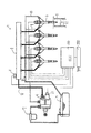
図5はエンジンのシリンダー5内への吸気と排気の模式図であり、4サイクルのディーゼルエンジンの実施例である。過給器TBの吸気タービン36により過給された空気は、エアクリーナー35から吸気タービン36、インタークーラー37を通過して吸気マニホールド38からシリンダー5内へ送られる構成である。39は吸気バルブであ、40はピストンである。48はカムでありロッカーアーム49を介して吸排気バルブ39、41を開閉させるものである。
FIG. 5 is a schematic diagram of intake and exhaust into the cylinder 5 of the engine, which is an embodiment of a four-cycle diesel engine. The air supercharged by the
シリンダー5内で燃焼した排ガスは、排気バルブ41から排気マニホールド42を通過した後、過給器TBの排気タービン45で過給器TBを回転させて排出される構成である。
The exhaust gas combusted in the cylinder 5 passes through the
このディーゼルエンジンは、排気ガスの一部を吸気側に混入させるためのEGR(排気再循環装置)回路44を有している。EGR回路で排気ガスの一部を吸気側に混入させることで酸素量(O2)を減らして、窒素酸化物Noxの発生を低減させるように構成している。ただし、EGR率が上昇しすぎると、逆に酸素量が少なくなって不完全燃焼になるので、燃焼状態によりEGR率を調節する必要がある。この調節は、EGRバルブ43にて行う。EGR回路44は排気マニホールド42と過給器TBの間に接続されており、前記EGRバルブ43を備えている。このEGRバルブ43の開閉具合でシリンダー5内への排気ガスの還元量が変化する。
The diesel engine has an EGR (exhaust gas recirculation device)
排気タービン45を通過後の排気ガスは、後処理装置46を通過してマフラー50から大気中に排出される。後処理装置46は、酸化触媒(DOC)46aとディーゼルパティキュレートフィルター(DPF)46bとから構成されている。
The exhaust gas that has passed through the
酸化触媒(DOC)は不燃物室を燃焼させるものであり、ディーゼルパティキュレートフィルター(DPF)は粒状化物室(PM)を捕集するためのものである。前記EGRバルブ43と絞り弁47については、ECU100により制御される構成である。後処理装置46はディーゼルパティキュレートフィルター(DPF)46bのみで構成してもよい、酸化触媒(DOC)を設けると不燃物質が燃焼するので、よりクリーンな排気ガスとなる。
The oxidation catalyst (DOC) burns the incombustible material chamber, and the diesel particulate filter (DPF) is for collecting the granulated material chamber (PM). The
DPF46bは、排気ガスの温度が低い状態(低負荷)が長時間続くと、PMが溜まってきて能力の低下が懸念される。そこで、後処理装置46の下手側に絞り弁47を設け、この絞り弁47を絞るとDPF内の圧力が高く保持されるので温度も高くなる。これにより、高い温度の影響により、DPF46bの再生が可能となる。即ち、高い温度の排気ガスがDPF46bを通過すると、DPF46b内に存在しているPMが焼き飛ばされることでDPF46bが再生される。
When the state of the exhaust gas is low (low load) continues for a long time, the
DPF46bを再生させるためのDPF再生運転としては、EGRバルブ43と絞り弁47の両方を絞る。そして、燃料噴射タイミングのリタード(遅角)と合わせてDPF46b内のガス温度を上昇させ、DPF46b再生に入るようにする。これにより、燃料のアフター噴射(排気ガス温度を上昇させるため)は不要となったり、アフター噴射の回数を減らすことができるようになるので、燃料消費量を抑制できて環境にもよい。
In the DPF regeneration operation for regenerating the
このようなDPF再生運転を行うための条件としては、後処理装置46の上手側に圧力センサ52を設けておいて、この圧力センサ52の値が所定値以上になるとDPF46b内にPMが蓄積して抵抗となっている状態なので、DPF再生運転を行うようにする。
As a condition for performing such a DPF regeneration operation, a
また、DPF再生運転に入った状態が長時間続くと、過熱状態となってしまいDPF46bが損傷してしまう。そこで、後処理装置46の下手側に温度センサ53を設け、この温度センサ53の値が所定値を超えるとDPF再生運転を止めて通常運転に戻るようにする。
Further, if the state in which the DPF regeneration operation is started continues for a long time, the
通常の運転は、EGRバルブ43と絞り弁47を同時に制御してEGR量を適宜コントロールするようにする。特に、絞り弁47を有することで、DPF46b内のガス温度を高く保持することができるようになる。
In normal operation, the
前記EGR回路44の入口部分にはEGRバルブ43を設け、ECU100で制御する構成としていたが、EGR回路44の途中に逆止弁51を設け、一定の比率のみ排気ガスを還元するようにして廉価な構成としてもよい。
The
前記過給器TBの過給圧が低い状態で全負荷時の燃料を噴射すると、空気過剰率が低下して黒煙が多く排出されるようになる。そこで、過給圧が下がると燃料噴射量を制限することは従来から公知の技術である。 When fuel at full load is injected while the supercharging pressure of the supercharger TB is low, the excess air ratio decreases and a large amount of black smoke is discharged. Therefore, it is a conventionally known technique to limit the fuel injection amount when the supercharging pressure decreases.
ところが、このような制御を行うと、トラクターがローアイドル回転数からハイアイドル回転数に回転を上げてから、作業機21を下げて作業を開始する一連の流れの中で、過給器TBの過給遅れのために作業開始時に低過給圧時の燃料噴射量制限に引っかかってしまい、出力不足となってエンジン回転数ドロップを生じてしまうという欠点がある。 However, when such control is performed, the turbocharger TB is turned on in a series of processes in which the tractor increases the rotation from the low idle rotation speed to the high idle rotation speed and then starts the operation by lowering the work implement 21. Due to the supercharging delay, the fuel injection amount restriction at the time of low supercharging pressure is caught at the start of work, and there is a drawback that the engine speed drops due to insufficient output.
そこで、負荷に応じて低過給時の燃料噴射量の制限値を変更するようにする。具体的には、作業機21の位置で変更するようにする。即ち、作業機21の位置が圃場面に近い状態(下降中)では、燃料噴射量の制限値を緩くするか、又は燃料噴射量の制限を実施しないようにする。このように、過給器TBが低過給圧であっても、エンジンに負荷が作用すると予測される場面や、負荷が作用する直前の場面において燃料噴射量の制限値を変更したり解除することで、エンジン回転数のドロップを防止できるようになる。また、実際のエンジンドロップが始まってから燃料噴射量の制限値を緩くしたり解除したりしても、間に合わない場合があり作業効率が低下してしまうが、このような不具合も防止できるようになる。 Therefore, the limit value of the fuel injection amount at the time of low supercharging is changed according to the load. Specifically, the position is changed at the position of the work machine 21. That is, when the position of the work implement 21 is close to the farm scene (descent), the limit value of the fuel injection amount is relaxed or the fuel injection amount is not limited. As described above, even when the supercharger TB has a low supercharging pressure, the limit value of the fuel injection amount is changed or released in a scene where a load is expected to act on the engine or a scene immediately before the load acts. As a result, the engine speed can be prevented from dropping. Also, even if the fuel injection amount limit value is loosened or released after the actual engine drop has started, it may not be in time and work efficiency will be reduced, but such problems can be prevented. Become.
前記作業機21の位置の検出方法としては、作業機21を支持しているリフトアームの角度を検出(図3のリフトアーム角度センサ22aで検出)するようにしてもよいし、作業機21の昇降位置をポジションセンサで検出するように構成してもよい。
As a method for detecting the position of the work implement 21, the angle of the lift arm that supports the work implement 21 may be detected (detected by the lift
図6は前述した通常作業モードB(アイソクロナス制御)の別実施例である。
アイソクロナス制御の場合、負荷がエンジンの全負荷性能を超える場合には、一気にエンストしてしまうという不具合があるので、これを防止する必要がある。
FIG. 6 shows another embodiment of the normal operation mode B (isochronous control) described above.
In the case of isochronous control, when the load exceeds the full load performance of the engine, there is a problem that the engine stalls at a stretch, and it is necessary to prevent this.
そこで、最大トルク点D以下の速度設定の場合は、走行モードA(ドループ制御)となるように構成する。これにより、エンストに陥ることなくエンジン回転数は下降することで、運転者は過負荷状態を知ることが可能となる。 Therefore, in the case of speed setting below the maximum torque point D, the travel mode A (droop control) is set. As a result, the engine speed decreases without falling into the engine stall, so that the driver can know the overload state.
また、ラインFは負荷80%ラインであるが、この負荷率80%以上の場合のみにおいて、ドループ制御Aとなり、負荷率80%未満についてはアイソクロナス制御Bを保持してもよい。これにより、エンジンの性能を極力最大源発揮できると共に、作業能率の低下も防止できるようになる。 The line F is an 80% load line, but only when the load factor is 80% or more, the droop control A is performed, and the isochronous control B may be held for a load factor less than 80%. As a result, the engine performance can be maximized as much as possible, and a reduction in work efficiency can be prevented.
図4の説明で前述したように、トラクターにおいてはエンジン回転数を変更する手段としてアクセルペダル23とアクセルレバー25の2系統を有している。そして、アイソクロナス制御Bを行うときには、アクセルレバー25を操作してエンジン回転数を所定の一定回転数となるようにしている。
As described above with reference to FIG. 4, the tractor has two systems of an
しかしながら、作業中において、アクセルレバー25を操作してアイソクロナス制御Bのエンジン回転数を変更することは容易にできない。そこで、アクセルペダル23をポンピングすることで、エンジン回転数を一定回転数だけ上昇させるようにする。これにより、アイソクロナス制御B時において、微妙なエンジン回転数の調節が可能となる。
However, it is not easy to change the engine speed of the isochronous control B by operating the
また、アクセルペダル23とアクセルレバー25の2系統を有している場合、次のような制御も可能となる。即ち、アクセルレバー25にてエンジン回転数を指示して作業中(ドループ制御A)において、作業負荷の増大によりエンジン回転数が下がった際、アクセルペダル23が踏まれると、アイソクロナス制御Bへとモード変更を行うように構成する。これにより、エンジン回転数の負荷の大小に関わらずエンジン回転数を保持して良好な作業が可能となる。
Further, when the two systems of the
また、作業機21を使用しない路上走行時においては、アクセルペダル23のみを有効とし、作業機21を使用する作業時においては、アクセルペダル23とアクセルレバー25のエンジン指示回転数のうち、エンジン回転数が高い方を有効回転数として使用するようにする。図8のステップS1で路上走行モードか作業走行モードかの判定を行う。この判定は、作業機21を駆動状態で判定する。作業機21を使用していない路上走行モードであれば、ステップS4へ進んでアクセルペダル23にて指示されるエンジン回転数でエンジンを制御する。
Further, when traveling on the road without using the work implement 21, only the
また、作業機21を使用する作業モードであれば、ステップS3へ進んでアクセルペダル23とアクセルレバー25のエンジン指示回転数のうち、エンジン回転数が高い方を読み取る。そして、ステップS4へ進んで読み取ったエンジン回転数で制御する。これにより、操作性と作業性が向上するようになり、路上走行時でのアクセルレバー25使用の危険性を防止できる。そして、特に、自動車間隔での運転が可能となる。
If the work mode uses the work implement 21, the process proceeds to step S <b> 3, and the higher engine speed of the engine instruction speeds of the
作業機21を昇降する油圧シリンダ21aにおいては、作業機21に大きな負荷が作用すると作業機21自体が上方に移動するため、油圧シリンダ21aは縮む側に移動し、油圧シリンダ21a内のオイルは抜ける方向に移動する。そこで、このオイル量を検出することで、作業機21自体に負荷が作用していると判断し、エンジンの燃料噴射量を増加させてエンジン回転数のドロップを防止するようにする。
In the
また、作業機21自体に作用する負荷が少ない 場合には、作業機21は下げ方向となるので、油圧シリンダ21aは伸び側となり、オイルは油圧シリンダ21a内に流れる方向となる。このオイル量を検出することで、作業機21自体に作用している負荷は小さいと判断し、エンジンの燃料噴射量を減らす制御を行う構成とする。これにより、燃費改善とスモーク低減が図れるようになる。
Further, when the load acting on the work machine 21 itself is small, the work machine 21 is in the lowering direction, so that the
図3に示している22aはリフトアーム角度センサであるが、この角度(作業機21の昇降位置)に応じて燃料噴射量を制御するように構成してもよい。具体的には、リフトアーム角度センサ22aが作業機21の下降状態を検出すると、作業機21に作用する負荷増大の状態が予測されるため、燃料噴射量を増大させるようにする。これにより、エンジン回転数の低下を防止して能率のよい作業が可能となる。
Although 22a shown in FIG. 3 is a lift arm angle sensor, you may comprise so that fuel injection quantity may be controlled according to this angle (the raising / lowering position of the working machine 21). Specifically, when the lift
また、リフトアーム角度センサ22aが作業機21の上昇状態を検出すると、作業機21に作用する負荷減少の状態が予測されるため、燃料噴射量を減少させるようにする。これにより、無駄な燃料消費を抑制できて環境にも配慮した能率のよい作業が可能となる。このように、作業機21の状態変化を事前に知ることで、効率のよい作業が可能となる。
Further, when the lift
図9と図10については、アクセルペダル23とアクセルレバー25を使用時において、路上走行モードと作業走行モードでそれぞれエンジン回転数の制御に特徴を持たせるように構成する。
9 and 10, when the
即ち、アクセルペダル23使用時の路上走行モードにおいてはAパターンとし、自動車に近い俊敏な吹き上がり性能を有する制御とする。アクセルペダル23使用時の作業走行モードにおいてはBパターンとし、空ふかしによる過度の吹き上がりや、黒煙排出を抑制した設定の制御とする。
That is, in the road running mode when the
また、アクセルレバー25使用時の路上走行モードにおいてはCパターンとし、空ふかしによる過度の吹き上がりや、黒煙排出を抑制した設定の制御とする。アクセルレバー25使用時の作業走行モードにおいてはDパターンとし、スムーズに作業に移行できる調整とする。図10には、前記Aパターン、Bパターン、Cパターン、及びDパターンのアクセル開度(%)とアクセル感度(%)の関係図を示している。また、図11のように、エンジンの冷却水温に応じて実アクセル感度を補正するように構成してもよい。
In the on-road driving mode when the
図12はエンジン回転数とエンジン出力の関係のトルクカーブラインを示したものである。ラインLAは路上走行時におけるトルクカーブであり、ラインLBは圃場内における作業走行時におけるトルクカーブラインである。 FIG. 12 shows a torque curve line of the relationship between the engine speed and the engine output. Line LA is a torque curve during traveling on the road, and line LB is a torque curve line during working traveling in the field.
このように、路上走行時と作業走行時とでは、トルクカーブラインを変更するように制御する。路上走行時のトルクラインLAの特徴としては、発進時に高トルクであり、その他の走行時は低トルクに設定している。これにより、スムーズな発進が可能になると共に、燃費改善とスモーク低減となる。 In this way, control is performed so as to change the torque curve line when traveling on the road and during traveling on the road. As a characteristic of the torque line LA when traveling on the road, the torque is set to a high torque at the time of starting and to a low torque during other traveling. As a result, a smooth start is possible, and fuel consumption is improved and smoke is reduced.
また、作業走行時のトルクラインLBについては、作業時における負荷の増大を考慮して、高回転域で高トルクとなるように設定している。路上走行時と作業走行時の判断は、作業機21の駆動、副変速の位置等で判断する。 Further, the torque line LB at the time of work travel is set so that the torque becomes high in a high rotation range in consideration of an increase in load during work. Judgment when traveling on the road and when traveling on the road is made based on the driving of the work implement 21, the position of the sub-shift, and the like.
トラクターやコンバイン等の農作業機を始め一般車両にも利用可能である。 It can be used for farm vehicles such as tractors and combiners as well as general vehicles.
B アイソクロナス制御
TB 過給器
PM 粒状化物質
21 作業機
23 アクセルペダル
25 アクセルレバー
43 EGRバルブ
44 EGR回路
45 排気タービン
46 排気ガス後処理装置
46b ディーゼルパティキュレートフィルタ(DPF)
47 絞り弁
52 圧力センサ
53 温度センサ
100 エンジンコントロールユニット(ECU)
B Isochronous control TB Supercharger PM Granulated material
21 working machines
23 accelerator pedal
25
47
Claims (2)
前記排気ガス後処理装置(46)を通過後の排気ガスの温度を測定する温度センサ(53)を設け、温度センサ(53)が所定値以上を検出すると、前記EGRバルブ(43)と絞り弁(47)の絞り状態を開き側に制御し、
作業走行中において、アクセルレバー(25)を操作してアイソクロナス制御(B)で制御中、アクセルペダル(23)をポンピング操作してエンジン回転数を一定回転数だけ上昇させるエンジンコントロールユニット(100)を設けたことを特徴とするトラクタ。 A supercharger (TB), an EGR circuit (44) for reducing a part of the exhaust gas to the intake system, and a granulated substance in the exhaust gas at least on the lower side of the exhaust turbine (45) of the supercharger (TB) In a tractor equipped with an engine equipped with an exhaust gas aftertreatment device (46) having a diesel particulate filter (46b) for collecting (PM), an EGR valve (43) is provided at the entrance of the EGR circuit (44). The exhaust gas aftertreatment device (46) is provided with a pressure sensor (52) on the upper side and a throttle valve (47) on the lower side, and when the value of the pressure sensor (52) exceeds a predetermined value, the EGR valve (43 ) And the throttle valve (47) to the throttle side ,
A temperature sensor (53) for measuring the temperature of the exhaust gas after passing through the exhaust gas aftertreatment device (46) is provided, and when the temperature sensor (53) detects a predetermined value or more, the EGR valve (43) and the throttle valve The aperture state of (47) is controlled to the open side,
An engine control unit (100) for operating the accelerator lever (25) and controlling the accelerator pedal (23) while operating the accelerator lever (25) and pumping the accelerator pedal (23) to increase the engine speed by a fixed speed. A tractor characterized by being provided.
Priority Applications (1)
| Application Number | Priority Date | Filing Date | Title |
|---|---|---|---|
| JP2007049284A JP4983311B2 (en) | 2007-02-28 | 2007-02-28 | Tractor |
Applications Claiming Priority (1)
| Application Number | Priority Date | Filing Date | Title |
|---|---|---|---|
| JP2007049284A JP4983311B2 (en) | 2007-02-28 | 2007-02-28 | Tractor |
Publications (2)
| Publication Number | Publication Date |
|---|---|
| JP2008215076A JP2008215076A (en) | 2008-09-18 |
| JP4983311B2 true JP4983311B2 (en) | 2012-07-25 |
Family
ID=39835451
Family Applications (1)
| Application Number | Title | Priority Date | Filing Date |
|---|---|---|---|
| JP2007049284A Expired - Fee Related JP4983311B2 (en) | 2007-02-28 | 2007-02-28 | Tractor |
Country Status (1)
| Country | Link |
|---|---|
| JP (1) | JP4983311B2 (en) |
Families Citing this family (9)
| Publication number | Priority date | Publication date | Assignee | Title |
|---|---|---|---|---|
| JP5140536B2 (en) * | 2008-09-29 | 2013-02-06 | ヤンマー株式会社 | Combine |
| JP5102180B2 (en) * | 2008-11-12 | 2012-12-19 | ヤンマー株式会社 | Engine device for work vehicle |
| JP5315955B2 (en) * | 2008-11-26 | 2013-10-16 | 井関農機株式会社 | Tractor |
| JP5248377B2 (en) | 2009-03-16 | 2013-07-31 | 日立建機株式会社 | Hydraulic drive device for work machine |
| JP5575468B2 (en) * | 2009-12-22 | 2014-08-20 | ヤンマー株式会社 | Engine generator |
| JP5523858B2 (en) * | 2010-02-04 | 2014-06-18 | 三菱農機株式会社 | Self-removing combine |
| JP5350299B2 (en) * | 2010-03-18 | 2013-11-27 | ヤンマー株式会社 | Engine control device for work vehicle |
| JP5706557B2 (en) * | 2014-04-08 | 2015-04-22 | ヤンマー株式会社 | Work vehicle |
| JP2016138507A (en) * | 2015-01-27 | 2016-08-04 | ヤンマー株式会社 | Engine control device for work vehicle |
Family Cites Families (3)
| Publication number | Priority date | Publication date | Assignee | Title |
|---|---|---|---|---|
| JPH1137284A (en) * | 1997-07-18 | 1999-02-12 | Yanmar Agricult Equip Co Ltd | Automatic transmission of agricultural working vehicle |
| JP3454351B2 (en) * | 1998-12-11 | 2003-10-06 | トヨタ自動車株式会社 | Regeneration processing control device for particulate filter |
| JP4092913B2 (en) * | 2002-01-10 | 2008-05-28 | 三菱自動車工業株式会社 | Integrated control unit for exhaust purification system of diesel engine |
-
2007
- 2007-02-28 JP JP2007049284A patent/JP4983311B2/en not_active Expired - Fee Related
Also Published As
| Publication number | Publication date |
|---|---|
| JP2008215076A (en) | 2008-09-18 |
Similar Documents
| Publication | Publication Date | Title |
|---|---|---|
| JP4983311B2 (en) | Tractor | |
| JP2010229959A (en) | Diesel engine | |
| JP2013181406A (en) | Working vehicle | |
| JP5176834B2 (en) | Work vehicle | |
| JP2010156208A (en) | Diesel engine | |
| JP2014009639A (en) | Work vehicle | |
| JP2012229633A (en) | Tractor | |
| JP7234830B2 (en) | work vehicle | |
| JP2014088860A (en) | Work vehicle | |
| JP2010053795A (en) | Diesel engine | |
| JP2012207636A (en) | Working vehicle | |
| JP2022086869A (en) | Work vehicle | |
| JP2012137042A (en) | Working vehicle | |
| JP5651926B2 (en) | Agricultural machinery diesel engine | |
| JP2019044691A (en) | Tractor | |
| JP2018141454A (en) | Tractor | |
| JP2010007648A (en) | Diesel engine | |
| JP2012052459A (en) | Working vehicle | |
| JP2020165416A (en) | Tractor | |
| JP2021188557A (en) | Working vehicle | |
| JP2022073330A (en) | Work vehicle | |
| JP2021055639A (en) | Service vehicle | |
| JP2010106794A (en) | Working vehicle | |
| JP2013113263A (en) | Working vehicle | |
| JP2019210828A (en) | Tractor |
Legal Events
| Date | Code | Title | Description |
|---|---|---|---|
| A621 | Written request for application examination |
Free format text: JAPANESE INTERMEDIATE CODE: A621 Effective date: 20100301 |
|
| A977 | Report on retrieval |
Free format text: JAPANESE INTERMEDIATE CODE: A971007 Effective date: 20110526 |
|
| A131 | Notification of reasons for refusal |
Free format text: JAPANESE INTERMEDIATE CODE: A131 Effective date: 20110809 |
|
| A521 | Written amendment |
Free format text: JAPANESE INTERMEDIATE CODE: A523 Effective date: 20111011 |
|
| TRDD | Decision of grant or rejection written | ||
| A01 | Written decision to grant a patent or to grant a registration (utility model) |
Free format text: JAPANESE INTERMEDIATE CODE: A01 Effective date: 20120327 |
|
| A01 | Written decision to grant a patent or to grant a registration (utility model) |
Free format text: JAPANESE INTERMEDIATE CODE: A01 |
|
| A61 | First payment of annual fees (during grant procedure) |
Free format text: JAPANESE INTERMEDIATE CODE: A61 Effective date: 20120409 |
|
| R150 | Certificate of patent or registration of utility model |
Ref document number: 4983311 Country of ref document: JP Free format text: JAPANESE INTERMEDIATE CODE: R150 Free format text: JAPANESE INTERMEDIATE CODE: R150 |
|
| FPAY | Renewal fee payment (event date is renewal date of database) |
Free format text: PAYMENT UNTIL: 20150511 Year of fee payment: 3 |
|
| LAPS | Cancellation because of no payment of annual fees |