EP2415702A2 - Web guiding apparatus - Google Patents
Web guiding apparatus Download PDFInfo
- Publication number
- EP2415702A2 EP2415702A2 EP11175767A EP11175767A EP2415702A2 EP 2415702 A2 EP2415702 A2 EP 2415702A2 EP 11175767 A EP11175767 A EP 11175767A EP 11175767 A EP11175767 A EP 11175767A EP 2415702 A2 EP2415702 A2 EP 2415702A2
- Authority
- EP
- European Patent Office
- Prior art keywords
- angle bar
- support
- web
- end portion
- axis
- Prior art date
- Legal status (The legal status is an assumption and is not a legal conclusion. Google has not performed a legal analysis and makes no representation as to the accuracy of the status listed.)
- Withdrawn
Links
- 238000007639 printing Methods 0.000 claims abstract description 17
- 238000011144 upstream manufacturing Methods 0.000 claims 3
- 230000008878 coupling Effects 0.000 claims 2
- 238000010168 coupling process Methods 0.000 claims 2
- 238000005859 coupling reaction Methods 0.000 claims 2
- 230000007246 mechanism Effects 0.000 description 2
- 238000007645 offset printing Methods 0.000 description 2
- 230000015572 biosynthetic process Effects 0.000 description 1
- 230000004048 modification Effects 0.000 description 1
- 238000012986 modification Methods 0.000 description 1
- 239000000758 substrate Substances 0.000 description 1
- 230000037303 wrinkles Effects 0.000 description 1
Images



Classifications
-
- B—PERFORMING OPERATIONS; TRANSPORTING
- B65—CONVEYING; PACKING; STORING; HANDLING THIN OR FILAMENTARY MATERIAL
- B65H—HANDLING THIN OR FILAMENTARY MATERIAL, e.g. SHEETS, WEBS, CABLES
- B65H23/00—Registering, tensioning, smoothing or guiding webs
- B65H23/04—Registering, tensioning, smoothing or guiding webs longitudinally
- B65H23/32—Arrangements for turning or reversing webs
-
- B—PERFORMING OPERATIONS; TRANSPORTING
- B65—CONVEYING; PACKING; STORING; HANDLING THIN OR FILAMENTARY MATERIAL
- B65H—HANDLING THIN OR FILAMENTARY MATERIAL, e.g. SHEETS, WEBS, CABLES
- B65H2301/00—Handling processes for sheets or webs
- B65H2301/40—Type of handling process
- B65H2301/41—Winding, unwinding
- B65H2301/414—Winding
- B65H2301/4148—Winding slitting
-
- B—PERFORMING OPERATIONS; TRANSPORTING
- B65—CONVEYING; PACKING; STORING; HANDLING THIN OR FILAMENTARY MATERIAL
- B65H—HANDLING THIN OR FILAMENTARY MATERIAL, e.g. SHEETS, WEBS, CABLES
- B65H2801/00—Application field
- B65H2801/03—Image reproduction devices
- B65H2801/21—Industrial-size printers, e.g. rotary printing press
Definitions
- a web guiding apparatus includes an angle bar, and an angle bar support supporting the angle bar.
- the angle bar support has a first end portion and a second end portion.
- the web guiding apparatus also includes a first actuator coupled to the angle bar support for moving the first end portion along a first axis and a second actuator coupled to the angle bar support for moving the second end portion along a second axis different from the first axis.
Landscapes
- Folding Of Thin Sheet-Like Materials, Special Discharging Devices, And Others (AREA)
- Registering, Tensioning, Guiding Webs, And Rollers Therefor (AREA)
- Rotary Presses (AREA)
Abstract
Description
- The present invention relates to generally to printing presses and more particularly to web guiding apparatuses used in web printing presses.
- In web offset printing presses, printing units may print text and images on a web substrate. A folder may fold the printed web and cut the printed web into a plurality of signatures. The folder may include one or more angle bars that guide and reorient the web for folding and cutting. The angle bars may each be provided internally with air by an air source and direct the air towards the passing web through holes formed in an outer surface of each angle bar. The air may eliminate friction between the angle bars and the web to improve transport of the web through a printing press and to prevent the web guiding device from marking the web.
- In printing presses where the web is reoriented from traveling in a horizontal orientation (parallel to the ground) to a vertical orientation (traveling on one side, perpendicular to the ground) a relatively long length of the web is acted on by several lead rolls and a ninety degree angle bar to reorient the web. Examples of such arrangements are disclosed in commonly owned
U.S. Patent Application Nos. 12/322,738 ,12/322,767 12/322,768 12/322,775 - A web guiding apparatus is provided. The web guiding apparatus includes an angle bar, and an angle bar support supporting the angle bar. The angle bar support has a first end portion and a second end portion. The web guiding apparatus also includes a first actuator coupled to the angle bar support for moving the first end portion along a first axis and a second actuator coupled to the angle bar support for moving the second end portion along a second axis different from the first axis.
- A web guiding apparatus is also provided that includes a first support, a second support, a first angle bar for guiding a first web movably coupled to the first support and the second support and a second angle bar for guiding a second web movably coupled to the first support and the second support.
According to an embodiment, a web guiding apparatus is provided. The web guiding apparatus includes an angle bar and an angle bar support supporting the angle bar. The angle bar support has a first end portion and a second end portion. The web guiding apparatus also includes a first actuator coupled to the angle bar support for moving the first end portion along a vertical axis and a second actuator coupled to the angle bar support for moving the second end portion along a horizontal axis. A folder for a printing press is also provided. - The present invention is described below by reference to the following drawings, in which:
-
Fig. 1 schematically shows a side view of a web printing press according to an embodiment of the present invention; -
Figs. 2 to 4 schematically show a side view, a top view and a perspective view, respectively, of a folder of the web printing press shown inFig. 1 ; -
Figs. 5 and6 schematically show perspective views of a folder according to another embodiment of the present invention for merging multiple webs, or ribbons, into a ribbon bundle for longitudinal folding by a former; -
Fig. 7 schematically shows the spacing between certain components of the folder shown inFigs. 5 and6 ; -
Fig. 8 schematically shows a perspective view of the folder shown inFigs. 5 to 7 adjusted to transport wider ribbons; -
Fig. 9 schematically shows a perspective view of the folder shown inFigs. 5 to 8 transporting ribbons, with the position of one angle bar adjusted; and -
Fig. 10 schematically shows a perspective view of the shown inFigs. 5 to 9 , with a position of one compensator roll adjusted. -
Fig. 1 schematically shows a side view of aweb printing press 10 according to an embodiment of the present invention.Printing press 10 includes aprinting section 12 and afolder 14.Printing section 12, which includes a plurality ofprinting units 16, prints on atraveling web 18. Asweb 18 entersfolder 14,web 18 is guided by a horizontally alignedpull roll 20 and a horizontally alignedcompensator roll 22 to anangle bar 24, which reorientsweb 18 from a horizontal orientation (traveling on a width of web 18) to a vertical orientation (traveling on one side of web 18). After being reoriented byangle bar 24,web 18 passes through a nip formed by vertically alignedgather rolls pull rolls web 18. -
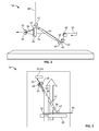
Figs. 2 to 4 schematically show a side view, a top view and a perspective view, respectively, offolder 14 guidingweb 18.Pull roll 20,compensator roll 22,angle bar 24,gather rolls pull rolls guide web 18 for longitudinal folding by horizontally aligned former 30.Angle bar 24 is coupled to anangle bar support 36 which allowsangle bar 24 to be adjusted in two different dimensions. Near an upper end portion ofangle bar support 36,angle bar support 36 is movably coupled to avertical support 38 and near a lower end portion ofangle bar support 36,angle bar support 36 is movably coupled to ahorizontal support 40. Anactuator 42 coupled to the upper end portion ofangle bar support 36 may moveangle bar support 36 up and down onsupport 38 and anactuator 44 coupled to the lower end portion ofangle bar support 36 may moveangle bar support 36 side-to-side onsupport 40.Actuators Fig. 4 for clarity. As a result,angle bar support 36 is vertically movable alongvertical support 38 and horizontally movable alonghorizontal support 40. During operation offolder 14, the position ofangle bar support 36 is secured in place with respect to bothvertical support 38 andhorizontal support 40. In an alternative embodiment,angle bar 24 may be fixedly coupled tovertical support 38 andhorizontal support 40 andvertical support 38 may be movable vertically andhorizontal support 40 may be moved horizontally to alter the orientation ofangle bar 24. - Because a length of
angle bar support 36 betweenvertical support 38 andhorizontal support 40 varies with the movement ofangle bar support 36 alongvertical support 38 andhorizontal support 40, at least one end ofangle bar support 36 may extend past either or both ofvertical support 38 andhorizontal support 40. For example, a lower end ofangle bar support 36 may be slidably received inhorizontal support 40, but an upper end ofangle bar support 36 may extend pastvertical support 38. In this case, a mechanism that couples angle bar support 36 andvertical support 38 together is axially slidable with respect to bothangle bar support 36 andvertical support 38. In another exemplary embodiment, at least one end ofangle bar support 36 may be telescopically movable and neither of the ends ofangle bar support 36 extends pastvertical support 38 orhorizontal support 36. -
Fig. 4 shows the spacing between important points offolder 14. A point P1 illustrates a position ofangle bar support 36 alongvertical support 38 and a point P4 illustrates a position ofangle bar support 36 alonghorizontal support 40. A point P2 illustrates where a plane ofhorizontal support 40 parallel to the ground intersects an axis V ofvertical support 38 and a point P3 illustrates where a plane ofvertical support 38 perpendicular to the ground intersects an axis H ofhorizontal support 40. In a preferred embodiment, a distance C between point P1 and point P2 always equals a distance A between point P3 and point P4 and distance B between point P2 and point P3 is greater than zero. As a result, ifangle bar support 36 is moved vertically by actuator 42 (Figs. 2 and 3 ),angle bar support 36 is moved the same distance horizontally by actuator 44 (Figs. 2 and 3 ). - In alternative embodiments,
horizontal support 40 may be aboveangle bar 24 with the upper end ofangle bar support 36 movably coupled tohorizontal support 40 and the lower end ofangle bar support 36 movably coupled tovertical support 38. -
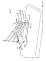
Figs. 5 and6 schematically show perspective views of afolder 114 for merging a plurality of webs or ribbons for example, four ribbons,ribbons ribbons offset printing section 12 as shown inFig. 1 and are formed by slitting single web 18 (Fig. 1 ) with a slitter. In alternative embodiments,webs folder 114. The plurality of webs or ribbons may include any number of webs or ribbons desired. The webs or ribbons may be slit from a single web or merged together to enter folder from a plurality of printing sections or any desired combination thereof. - Ribbons 18a, 18b, 18c, 18d, parallel to the ground, pass over a
pull roll 120 and then eachribbon respective compensator roll Compensator rolls space ribbons compensator rolls Ribbons respective angle bars ribbons ribbons rolls - Each
angle bar angle bar support angle bar support vertical support 138 and a lower end portion of eachangle bar support horizontal support 140. Eachangle bar support respective actuator vertical support 138. Eachangle bar support respective actuator horizontal support 140. As a result, angle bar supports 36a, 36b, 36c, 36d are independently vertically movable alongvertical support 138 and independently horizontally movable alonghorizontal support 140.Actuators Fig. 6 for clarity. -
Fig. 7 shows the spacing between important points offolder 114.Actuators Fig. 7 for clarity. Points P1a, P1b, P1c, P1d illustrate positions of respective angle bar supports 36a, 36b, 36c, 36d alongvertical support 138 and points P4a, P4b, P4c, P4d illustrate positions of respective angle bar supports 36a, 36b, 36c, 36d alonghorizontal support 140. Point P2' illustrates where a plane ofhorizontal support 140 that is perpendicular to an axis V' ofvertical support 138 intersects axis V' and point P3' illustrates where a plane ofvertical support 138 that is perpendicular to an axis H' ofhorizontal support 140 intersects axis H'. In a preferred embodiment, distances between point P1a, P1b, P1c, P1d and point P2' always equals respective distances between points P4a, P4b, P4c, P4d and point P3' and distance between point P2' and point P3' is greater than zero. As a result, if at least one of angle bar supports 36a, 36b, 36c, 36d is moved vertically alongvertical support 138 by therespective actuator Fig. 5 ), the at least one of theangle bar support horizontal support 140 by therespective actuator Fig. 5 ). For example, ifangle bar support 36a is moved vertically byactuator 42a (Fig. 5 ),angle bar support 36a is moved the same distance horizontally byactuator 44a (Fig. 5 ). -
Fig. 8 shows a perspective view offolder 114 adjusted to guideribbons ribbons Figs. 5 to 7 withangle bars wider ribbons angle bar support vertical support 138 by therespective actuator angle bar support horizontal support 140 by therespective actuator angle bar support vertical support 138. -
Fig. 9 shows a perspective view offolder 114 transportingribbons Fig. 7 , but with the position ofangle bar 24b adjusted.Angle bars Fig. 7 .Angle bar 24b is moved away fromangle bar 24a and towards angle bar 24c by movingangle bar support 36b upward onvertical support 138 byactuator 42b and movingangle bar support 36b sideways onhorizontal support 140 byactuator 44b the same distance thatangle bar support 36b is moved upward onvertical support 138. By adjusting the position ofangle bar 24b, a position ofweb 19b with respect to theribbons -
Fig. 10 shows a perspective view offolder 114 transportingribbons Fig. 6 , but with the position ofcompensator roll 22b adjusted. With respect toFig. 6 ,compensator roll 22b is moved radially away frompull roll 120 and towardsangle bar 24b via an adjusting actuator. The positions of any of compensator rolls 22a, 22b, 22c, 22d, independently or together, may be adjusted to accommodate changes in cut-off registration or to correct registration errors.Actuators Fig. 10 for clarity. - The present invention described herein advantageously provides a web guiding apparatus that may control the distance of the web from the ground when the web exits the web guiding apparatus or folder, may accommodate changes in the side to side locations of the web's entry point in the folder and may control the timing and/or registration of the web. Advantageously, the present web guiding apparatus may minimize the size and complexity of previous angle and turner bar mechanisms, may minimize the web length required to make the changes and may reduce the quantity of turner bar, angle bars or rolls needed. Adjustments to the web guiding apparatus may also be less complex.
- In the preceding specification, the invention has been described with reference to specific exemplary embodiments and examples thereof. It will, however, be evident that various modifications and changes may be made thereto without departing from the broader spirit and scope of the invention as set forth in the claims that follow. The specification and drawings are accordingly to be regarded in an illustrative manner rather than a restrictive sense.
Claims (22)
- A web guiding apparatus comprising:an angle bar;an angle bar support supporting the angle bar having a first end portion and a second end portion;a first actuator coupled to the angle bar support for moving the first end portion along a first axis; anda second actuator coupled to the angle bar support for moving the second end portion along a second axis different from the first axis.
- The web guiding apparatus recited in claim 1 further comprising a first support coincident with the first axis coupled to the first end portion of the angle bar support, the first actuator being configured to move the first end portion of the angle bar support along the first support.
- The web guiding apparatus recited in claim 2 further comprising a second support coincident with the second axis coupled to the second end portion of the angle bar support, the second actuator being configured to move the second end portion of the angle bar support along the second support.
- The web guiding apparatus recited in claim 3 wherein the first axis is vertical and the second axis is horizontal.
- The web guiding apparatus recited in any of the preceding claims further comprising:a second angle bar; anda second angle bar support supporting the second angle bar having a first end portion movably coupled to the first support for selective movement along the first axis and a second end portion movably coupled to the second support for selective movement along the second axis.
- The web guiding apparatus recited in claim 5 wherein the first axis is vertical and the second axis is horizontal.
- The web guiding apparatus recited in any of the preceding claims further comprising a horizontally aligned compensator roll upstream of the angle bar for directing a horizontally oriented web to the angle bar, and wherein the angle bar is configured to reorient the web vertically so the web is vertically oriented.
- The web guiding apparatus recited in claim 7 further comprising a pair of vertically aligned gather rolls downstream of the angle bar for receiving the vertically oriented web from angle bar.
- The web guiding apparatus recited in any of the preceding claims further comprising:a second angle bar;a second angle bar support supporting the second angle bar having a first end portion and a second end portion;a third actuator for moving the first end portion of the second angle bar support along the first axis; anda fourth actuator for moving the second end portion of the second angle bar support along the second axis.
- The web guiding apparatus as recited in any of the preceding claims further comprising:at least one further angle bar;at least one further angle bar support corresponding to and supporting the at least one further angle bar having a first end portion and a second end portion;at least two further actuators, one of the at least two further actuators moving the first end portion of the at least one further angle bar support along the first axis; and the other of the at least two further actuators moving the second end portion of the at least one further angle bar support along the second axis.
- A web guiding apparatus comprising:a first support;a second support;a first angle bar for guiding a first web movably coupled to the first support and the second support; anda second angle bar for guiding a second web movably coupled to the first support and the second support.
- The web guiding apparatus recited in claim 11 wherein the first support is coincident with a vertical axis and the second support is coincident with a horizontal axis.
- The web guiding apparatus recited in claim 11 or 12 further comprising:a first actuator for moving the first angle bar with respect to the first support;a second actuator for moving the first angle bar with respect to the second support;a third actuator for moving the second angle bar with respect to the first support; anda fourth actuator for moving the second angle bar with respect to the second support.
- The web guiding apparatus recited in any of the claims 11 to 13 further comprising:a first angle bar support coupling an upper end of the first angle bar to the first support and a second end of the first angle bar to the second support; anda second angle bar support coupling an upper end of the second angle bar to the first support and a lower end of the second angle bar to the second support.
- The web guiding apparatus recited in any of the claims 11 to 14 further comprising at least one further angle bar coupled to the first support and the second support.
- The web guiding apparatus recited in claim 15 wherein the first support is coincident with a vertical axis and the second support is coincident with a horizontal axis.
- The web guiding apparatus recited in any of the claims 11 to 16 further comprising a horizontally aligned first compensator roll upstream of the first angle bar for guiding the first web in a horizontal orientation to the first angle bar, the first angle bar configured to reorient the first web to a vertical orientation.
- The web guiding apparatus recited in claim 17 further comprising a horizontally aligned second compensator roll upstream of the second angle bar for guiding the second web in a horizontal orientation to the second angle bar, the second angle bar configured to reorient the second web to a vertical orientation.
- The web guiding apparatus recited in claim 18 further comprising a pair of vertically aligned gather rolls downstream of the first and second angle bars for merging the vertically oriented first and second webs.
- The web guiding apparatus recited in claim 19 further comprising a horizontally aligned former downstream of the gather rolls for longitudinally folding the merged first and second webs.
- A folder for a printing press comprising:a web guiding apparatus for guiding a web, the web guiding device including:an angle bar,an angle bar support supporting the angle bar having a first end portion and a second end portion,a first actuator coupled to the angle bar support for moving the first end portion along a first axis; anda second actuator coupled to the angle bar support for moving the second end portion along a second axis different from the first axis,a former located downstream of the web guiding apparatus; anda plurality of pull rolls pulling the web over the former.
- The folder as recited in claim 21 wherein the web guiding apparatus guides the web by reorienting the web with respect to the former.
Applications Claiming Priority (1)
| Application Number | Priority Date | Filing Date | Title |
|---|---|---|---|
| US12/806,020 US8235372B2 (en) | 2010-08-04 | 2010-08-04 | Web guiding apparatus |
Publications (2)
| Publication Number | Publication Date |
|---|---|
| EP2415702A2 true EP2415702A2 (en) | 2012-02-08 |
| EP2415702A3 EP2415702A3 (en) | 2012-04-04 |
Family
ID=44510771
Family Applications (1)
| Application Number | Title | Priority Date | Filing Date |
|---|---|---|---|
| EP11175767A Withdrawn EP2415702A3 (en) | 2010-08-04 | 2011-07-28 | Web guiding apparatus |
Country Status (2)
| Country | Link |
|---|---|
| US (1) | US8235372B2 (en) |
| EP (1) | EP2415702A3 (en) |
Families Citing this family (1)
| Publication number | Priority date | Publication date | Assignee | Title |
|---|---|---|---|---|
| DE102012001832B4 (en) * | 2012-02-01 | 2013-08-08 | Hochland Se | Process for processing a flowable food mass |
Family Cites Families (8)
| Publication number | Priority date | Publication date | Assignee | Title |
|---|---|---|---|---|
| GB279608A (en) * | 1926-09-29 | 1927-11-03 | Ernest Arthur Timson | Improvements in or relating to web-guiding devices for printing and other machines |
| US5016801A (en) * | 1990-08-28 | 1991-05-21 | Industrial Label Corporation | Multiple-ply web registration apparatus |
| EP0582927B1 (en) * | 1992-08-10 | 1997-11-19 | KOENIG & BAUER-ALBERT AKTIENGESELLSCHAFT | Turning bar for web material |
| DE4311438C2 (en) * | 1993-04-07 | 1997-06-19 | Koenig & Bauer Albert Ag | Turning bar for a material web |
| WO1997040985A1 (en) * | 1996-04-29 | 1997-11-06 | Koenig & Bauer Aktiengesellschaft | Turning-bar arrangement |
| DE10044070A1 (en) * | 1999-10-01 | 2001-04-26 | Heidelberger Druckmasch Ag | Device for selectively closing blowing openings in guide devices or bars of printing presses carrying printing material |
| DE10313774B4 (en) * | 2002-12-18 | 2006-12-14 | Koenig & Bauer Ag | Device for processing a moving material web |
| US7963515B2 (en) * | 2009-02-06 | 2011-06-21 | Goss International Americas, Inc. | Adjustable delivery web conversion apparatus and method |
-
2010
- 2010-08-04 US US12/806,020 patent/US8235372B2/en not_active Expired - Fee Related
-
2011
- 2011-07-28 EP EP11175767A patent/EP2415702A3/en not_active Withdrawn
Also Published As
| Publication number | Publication date |
|---|---|
| US8235372B2 (en) | 2012-08-07 |
| EP2415702A3 (en) | 2012-04-04 |
| US20120035039A1 (en) | 2012-02-09 |
Similar Documents
| Publication | Publication Date | Title |
|---|---|---|
| US5467179A (en) | Turnover device for a web-shaped recording medium | |
| US6152034A (en) | Former board arrangement in a web-fed rotary newspaper printing press | |
| US6802110B2 (en) | Web expanding device | |
| JP2001192169A (en) | Movable folding device and former device | |
| US20110050767A1 (en) | Variable format web press | |
| EP1982833A1 (en) | Turn bar assembly for rotary press | |
| JP3822845B2 (en) | Device for guiding the running web | |
| EP1655256A1 (en) | Method of presetting a printing press and web processing devices | |
| US9260266B2 (en) | Method for separating partial webs in a slitter winder | |
| US7513195B2 (en) | Printing machine comprising at least one printing group, one folder and at least one turn-and-mix stage | |
| US6575399B1 (en) | Web control matrix | |
| CN108290696B (en) | Winding device, processing equipment and the method that web of material is pulled in into winding device | |
| JP2004090635A (en) | Device and method of setting crop mark | |
| US8235372B2 (en) | Web guiding apparatus | |
| KR102499675B1 (en) | Device for cutting a web of material into individual sheets with a web storage | |
| US20070060460A1 (en) | Folding unit upper part | |
| EP0143741B1 (en) | Cross-folder for continuous forms | |
| JP2011178565A (en) | Sheet guide device, printed product manufacturing system equipped therewith, and method for manufacturing printed product | |
| JP5009965B2 (en) | Folding machine and rotary printing machine | |
| US20050034616A1 (en) | Web-spreading process and web-spreading device | |
| EP1064214B1 (en) | Former | |
| US9415955B2 (en) | Recording apparatus | |
| US6371901B1 (en) | Linear folding device and method | |
| CN102015498A (en) | Device and method for supplying strip material for folding formers | |
| EP0244761A2 (en) | Folding and cutting device for small in-line folding products |
Legal Events
| Date | Code | Title | Description |
|---|---|---|---|
| AK | Designated contracting states |
Kind code of ref document: A2 Designated state(s): AL AT BE BG CH CY CZ DE DK EE ES FI FR GB GR HR HU IE IS IT LI LT LU LV MC MK MT NL NO PL PT RO RS SE SI SK SM TR |
|
| AX | Request for extension of the european patent |
Extension state: BA ME |
|
| PUAI | Public reference made under article 153(3) epc to a published international application that has entered the european phase |
Free format text: ORIGINAL CODE: 0009012 |
|
| PUAL | Search report despatched |
Free format text: ORIGINAL CODE: 0009013 |
|
| AK | Designated contracting states |
Kind code of ref document: A3 Designated state(s): AL AT BE BG CH CY CZ DE DK EE ES FI FR GB GR HR HU IE IS IT LI LT LU LV MC MK MT NL NO PL PT RO RS SE SI SK SM TR |
|
| AX | Request for extension of the european patent |
Extension state: BA ME |
|
| RIC1 | Information provided on ipc code assigned before grant |
Ipc: B65H 23/26 20060101ALI20120301BHEP Ipc: B65H 23/32 20060101AFI20120301BHEP |
|
| 17P | Request for examination filed |
Effective date: 20120831 |
|
| STAA | Information on the status of an ep patent application or granted ep patent |
Free format text: STATUS: THE APPLICATION IS DEEMED TO BE WITHDRAWN |
|
| 18D | Application deemed to be withdrawn |
Effective date: 20150203 |