EP2415664A2 - Wing-to-body fairing with spray-on foam and noise reduction method - Google Patents
Wing-to-body fairing with spray-on foam and noise reduction method Download PDFInfo
- Publication number
- EP2415664A2 EP2415664A2 EP11176204A EP11176204A EP2415664A2 EP 2415664 A2 EP2415664 A2 EP 2415664A2 EP 11176204 A EP11176204 A EP 11176204A EP 11176204 A EP11176204 A EP 11176204A EP 2415664 A2 EP2415664 A2 EP 2415664A2
- Authority
- EP
- European Patent Office
- Prior art keywords
- fairing
- foam
- insulation
- spray
- insulation foam
- Prior art date
- Legal status (The legal status is an assumption and is not a legal conclusion. Google has not performed a legal analysis and makes no representation as to the accuracy of the status listed.)
- Granted
Links
Images
Classifications
-
- B—PERFORMING OPERATIONS; TRANSPORTING
- B64—AIRCRAFT; AVIATION; COSMONAUTICS
- B64C—AEROPLANES; HELICOPTERS
- B64C1/00—Fuselages; Constructional features common to fuselages, wings, stabilising surfaces or the like
- B64C1/40—Sound or heat insulation, e.g. using insulation blankets
-
- B—PERFORMING OPERATIONS; TRANSPORTING
- B64—AIRCRAFT; AVIATION; COSMONAUTICS
- B64C—AEROPLANES; HELICOPTERS
- B64C1/00—Fuselages; Constructional features common to fuselages, wings, stabilising surfaces or the like
- B64C1/26—Attaching the wing or tail units or stabilising surfaces
-
- B—PERFORMING OPERATIONS; TRANSPORTING
- B64—AIRCRAFT; AVIATION; COSMONAUTICS
- B64C—AEROPLANES; HELICOPTERS
- B64C7/00—Structures or fairings not otherwise provided for
-
- Y—GENERAL TAGGING OF NEW TECHNOLOGICAL DEVELOPMENTS; GENERAL TAGGING OF CROSS-SECTIONAL TECHNOLOGIES SPANNING OVER SEVERAL SECTIONS OF THE IPC; TECHNICAL SUBJECTS COVERED BY FORMER USPC CROSS-REFERENCE ART COLLECTIONS [XRACs] AND DIGESTS
- Y10—TECHNICAL SUBJECTS COVERED BY FORMER USPC
- Y10T—TECHNICAL SUBJECTS COVERED BY FORMER US CLASSIFICATION
- Y10T29/00—Metal working
- Y10T29/53—Means to assemble or disassemble
Definitions
- the disclosure generally relates to wing to body fairings in aircraft. More particularly, the disclosure relates to a wing to body fairing with foam which reduces vibration, fatigue and cabin noise in an aircraft and a method of reducing cabin noise or reducing panel vibration in an aircraft.
- insulation blankets may be placed on wing to body fairings to reduce cabin noise to acceptable levels by damping vibration of the wing to body fairing panels.
- insulation blankets may contribute excessive weight to the fairings.
- insulation blankets may not be effective in damping vibration of the fairing panels during operation of the aircraft.
- the disclosure is generally directed to a fairing with spray-on foam, which reduces vibration, fatigue and cabin noise in an aircraft.
- An illustrative embodiment of the fairing includes a fairing body having a fairing interior and an interior surface and an insulating foam layer provided on the interior surface of the fairing body.
- the disclosure is further generally directed to a method of reducing cabin noise or reducing panel vibration in an aircraft.
- An illustrative embodiment of the method includes providing a fairing having a fairing body with an interior surface, providing an insulating foam, applying the spray-on insulation foam to the interior surface of the fairing body and installing the fairing on an aircraft.
- the method of reducing cabin noise or reducing panel vibration in an aircraft may include providing a fairing having a fairing body including a plurality of fairing panels with an interior surface; providing a spray-on insulation foam; spraying the spray-on insulation foam on the interior surface of the fairing body; and installing the fairing on an aircraft.
- the fairing 1 may be a wing to body fairing (WTBF) of a commercial aircraft, for example and without limitation.
- the fairing 1 may include a fairing body 1a having a fairing interior 5.
- the fairing body 1a may have multiple fairing panels 2 which are assembled into the fairing body 1a according to the knowledge of those skilled in the art.
- Each fairing panel 2 may have an exterior panel surface 3 which generally faces away from the fairing interior 5 of the fairing body 1a and an interior panel surface 4 which generally faces the fairing interior 5 of the fairing body 1a.
- the fairing body 1a may have a fairing edge 6.
- At least one insulation foam layer 8 may be sprayed on the interior panel surfaces 4 of the fairing panels 2 of the fairing body 1a.
- the insulation foam layer 8 may be closed cell polyurethane spray-on insulation foam which is sprayed onto the interior panel surfaces 4 of the fairing panels 2.
- a polyurethane foam which is suitable for the spray-on insulation foam layer 8 is TIGER FOAM@ which can be obtained from Commercial Thermal Solutions, Inc. of Spring Lake, NJ (www.tigerfoam.com).
- the insulation foam layer 8 may be applied to the interior panel surfaces 4 of the fairing panels 2 using an alternative application method.
- the insulation foam layer 8 may be a prepared foam layer which is applied to the interior panel surfaces 4 using adhesive and pressure.
- the insulation foam layer 8 may be contiguously applied to the interior panel surfaces 4 of the fairing panels 2. Therefore, the insulation foam layer 8 may be continuous generally throughout the entire surface area which is represented by the interior panel surfaces 4 of the fairing panels 2.
- the insulation foam layer 8 may have a core foam portion 9.
- a tapered foam portion 10 may extend outwardly from the edges of the core foam portion 9 toward the fairing edge 6 of the fairing body 1a. Taper is used to control weight and enhance handling durability. Edges are not so important relative to center portion for foam benefit.
- a fairing flange 2a may extend between the tapered foam portion 10 and the fairing edge 6. The fairing flange 2a may facilitate attachment of the fairing body 1a to the structural elements (not shown) of an aircraft (not shown) according to the knowledge of those skilled in the art.
- the insulation foam layer 8 may be omitted from the fairing flange 2a.
- the insulation foam layer 8 which is a closed cell polyurethane foam, may have a density of about 1.75 lb/ft 3 , or a density in the range between about 1.50 and about 2.0 lb/ft 3 .
- the core foam portion 9 of the insulation foam layer 8 may have a thickness of about 2 inches.
- the thickness of the tapered foam portion 10 may decrease from about 2 inches to 0 inches from the core foam portion 9 to the fairing flange 2a.
- the main feature is to eliminate corners that may interfere with the handling of the panel(s).
- Spray on foam insulation is typically not uniform in thickness upon application. Secondary machining to a specific thickness dimension is typically needed. In one embodiment the spray on foam may not be machined and the resulting thickness may range from 0.5 to 3 inches.
- insulation pins 12 may be installed on the interior panel surface 4 of each fairing panel 2.
- the insulation pins 12 may ensure that the insulation foam layer 8 remains on each fairing panel 2 throughout the service life of the fairing panels 2 while also ensuring the transfer of vibration energy from panel to foam.
- the fairing 1 may be installed on a commercial aircraft (not shown) according to the knowledge of those skilled in the art. During operation of the aircraft, the insulation foam layer 8 may reduce wing-to-body fairing vibration, fatigue and cabin noise by dissipating energy via a damping and mass effect.
- a foam may be provided.
- the foam may be a closed cell polyurethane spray-on insulation foam, for example and without limitation.
- a polyurethane foam which is suitable for the spray-on foam layer is TIGER FOAM@ which can be obtained from Commercial Thermal Solutions, Inc. of Spring Lake, NJ (www.tigerfoam.com).
- the foam may be a prepared foam layer.
- a wing to body fairing having wing to body fairing panels may be provided.
- the foam may be applied to the interior surfaces of the wing to body panels of the fairing by spraying or by application using adhesive and pressure to form an insulation foam layer on the interior surfaces of the wing to body panels.
- the insulation foam layer may have a core foam portion and a tapered foam portion which extends from the edges of the core foam portion.
- the fairing may be installed on an aircraft. During operation of the aircraft, the insulation foam layer may reduce wing-to-body fairing vibration, fatigue and cabin noise by dissipating energy via a damping effect.
- insulation pins may be provided.
- the insulation pins may be installed on the interior surfaces of the wing body panels of the fairing prior to application of the foam on the interior surfaces of the wing to body fairing panels in block 306. The insulation pins may ensure that the insulation foam layer remains on each fairing panel throughout the service life of the fairing panels.
- embodiments of the disclosure may be used in the context of an aircraft manufacturing and service method 78 as shown in FIG. 4 and an aircraft 94 as shown in FIG. 5 .
- exemplary method 78 may include specification and design 80 of the aircraft 94 and material procurement 82.
- component and subassembly manufacturing 84 and system integration 86 of the aircraft 94 takes place.
- the aircraft 94 may go through certification and delivery 88 in order to be placed in service 90.
- the aircraft 94 may be scheduled for routine maintenance and service 92 (which may also include modification, reconfiguration, refurbishment, and so on).
- Each of the processes of method 78 may be performed or carried out by a system integrator, a third party, and/or an operator (e.g., a customer).
- a system integrator may include without limitation any number of aircraft manufacturers and major-system subcontractors
- a third party may include without limitation any number of vendors, subcontractors, and suppliers
- an operator may be an airline, leasing company, military entity, service organization, and so on.
- a further embodiment of method 78 may include receiving an assembled aircraft having fairing.
- the aircraft may further include a wing to body faring.
- the aircraft may further have a wing to body fairing where located aft of a wheel well.
- the aircraft may further have a wing to body fairing where located aft of a wheel well where the wheel well include a opening that exposes the interior of the wheel well to the exterior of the aircraft.
- the method may include removing a panel of the faring and applying a foam insulation to an interior surface of the panel.
- the method may further include machining the foam to a desired thickness and shape.
- the method may further include a spraying on a foam insulation material that bonds to the surface of the panel.
- the aircraft 94 produced by exemplary method 78 may include an airframe 98 with a plurality of systems 96 and an interior 100.
- high-level systems 96 include one or more of a propulsion system 102, an electrical system 104, a hydraulic system 106, and an environmental system 108. Any number of other systems may be included.
- an aerospace example is shown, the principles of the invention may be applied to other industries, such as the automotive industry.
- the apparatus embodied herein may be employed during any one or more of the stages of the production and service method 78.
- components or subassemblies corresponding to production process 84 may be fabricated or manufactured in a manner similar to components or subassemblies produced while the aircraft 94 is in service.
- one or more apparatus embodiments may be utilized during the production stages 84 and 86, for example, by substantially expediting assembly of or reducing the cost of an aircraft 94.
- one or more apparatus embodiments may be utilized while the aircraft 94 is in service, for example and without limitation, to maintenance and service 92.
- a method of reducing cabin noise in an aircraft may comprise providing a fairing having a fairing body with an interior surface, applying an insulation foam to the interior surface of the fairing body, and the method further comprising removing said fairing from an assembled aircraft.
- the method may further comprise, installing said fairing having the applied insulation foam on said aircraft.
- the method may further comprise providing insulation foam comprises providing a spray-on polyurethane insulation foam.
- the method may further comprise providing a spray-on polyurethane insulation foam comprises providing a closed-cell spray-on polyurethane insulation foam.
- the method may further comprise spraying a spray-on insulation foam layer having a core foam portion and a tapered foam portion extending from said core foam portion on said interior surface of said fairing body comprises spraying a spray-on insulation foam layer having a core foam portion with a thickness of about 2 inches and a tapered foam portion extending from said core foam portion with a thickness of about 0 inches to about 2 inches on said interior surface of said fairing body.
- a fairing embodied may comprise a fairing body having a fairing interior and an interior surface; and an insulation foam layer provided on said interior surface of said fairing body.
- the fairing may further comprise a fairing body comprises a plurality of fairing panels each having an interior panel surface, and wherein said insulation foam layer is provided on said interior panel surface of said plurality of fairing panels.
- the fairing may further comprise an insulation foam layer comprising a closed cell polyurethane foam layer.
- the fairing may further comprise a wing to body fairing.
- the fairing may further comprise an insulation foam layer comprising a core foam portion and a tapered foam portion extending from said core foam portion.
- the fairing may further comprise a core foam portion having a thickness of about 2 inches.
- the fairing may further comprise a tapered foam portion having a thickness of about 0 inches to about 2 inches.
- the fairing may further comprise a fairing flange having a fairing edge extending from said fairing body and wherein said spray-on insulation foam layer is omitted from said fairing flange from said tapered foam portion to said fairing edge.
Landscapes
- Engineering & Computer Science (AREA)
- Aviation & Aerospace Engineering (AREA)
- Mechanical Engineering (AREA)
- Laminated Bodies (AREA)
Abstract
Description
- The disclosure generally relates to wing to body fairings in aircraft. More particularly, the disclosure relates to a wing to body fairing with foam which reduces vibration, fatigue and cabin noise in an aircraft and a method of reducing cabin noise or reducing panel vibration in an aircraft.
- In modem commercial aircraft, heavy insulation blankets may be placed on wing to body fairings to reduce cabin noise to acceptable levels by damping vibration of the wing to body fairing panels. However, insulation blankets may contribute excessive weight to the fairings. Moreover, insulation blankets may not be effective in damping vibration of the fairing panels during operation of the aircraft.
- Therefore, a wing to body fairing with foam which reduces vibration, fatigue and cabin noise in an aircraft and a method of reducing cabin noise or reducing panel vibration in an aircraft are needed.
- The disclosure is generally directed to a fairing with spray-on foam, which reduces vibration, fatigue and cabin noise in an aircraft. An illustrative embodiment of the fairing includes a fairing body having a fairing interior and an interior surface and an insulating foam layer provided on the interior surface of the fairing body.
- The disclosure is further generally directed to a method of reducing cabin noise or reducing panel vibration in an aircraft. An illustrative embodiment of the method includes providing a fairing having a fairing body with an interior surface, providing an insulating foam, applying the spray-on insulation foam to the interior surface of the fairing body and installing the fairing on an aircraft.
- In some embodiments, the method of reducing cabin noise or reducing panel vibration in an aircraft may include providing a fairing having a fairing body including a plurality of fairing panels with an interior surface; providing a spray-on insulation foam; spraying the spray-on insulation foam on the interior surface of the fairing body; and installing the fairing on an aircraft.
-
-
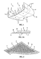
FIG. 1 is a bottom perspective view of an illustrative embodiment of a wing to body fairing with spray-on foam. -
FIG. 1A is a cross-sectional view of a portion of a fairing panel of the wing to body fairing, with a spray-on foam layer provided on an interior panel surface of the fairing panel. -
FIG. 2 is a perspective view of a portion of a fairing panel of the wing to body fairing, with a spray-on foam layer deposited on the fairing panel. -
FIG. 2A is a cross-sectional view of a portion of a fairing panel of the wing to body fairing, with insulation pins extending from the interior panel surface and a spray-on foam layer provided on the insulation pins and the interior panel surface of the fairing panel. -
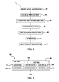
FIG. 3 is a flow diagram of an illustrative embodiment of a method of reducing cabin noise or reducing panel vibration in an aircraft. -
FIG. 4 is a flow diagram of an aircraft production and service methodology. -
FIG. 5 is a block diagram of an aircraft. - The following detailed description is merely exemplary in nature and is not intended to limit the described embodiments or the application and uses of the described embodiments. As used herein, the word "exemplary" or "illustrative" means "serving as an example, instance, or illustration." Any implementation described herein as "exemplary" or "illustrative" is not necessarily to be construed as preferred or advantageous over other implementations. All of the implementations described below are exemplary implementations provided to enable persons skilled in the art to practice the disclosure and are not intended to limit the scope of the appended claims. Furthermore, there is no intention to be bound by any expressed or implied theory presented in the preceding technical field, background, brief summary or the following detailed description.
- Referring initially to
FIGS. 1-2A , an illustrative embodiment of the wing to body fairing with foam, hereinafter fairing, is generally indicated by reference numeral 1. In some embodiments, the fairing 1 may be a wing to body fairing (WTBF) of a commercial aircraft, for example and without limitation. The fairing 1 may include afairing body 1a having afairing interior 5. In some embodiments, thefairing body 1a may havemultiple fairing panels 2 which are assembled into thefairing body 1a according to the knowledge of those skilled in the art. Eachfairing panel 2 may have anexterior panel surface 3 which generally faces away from thefairing interior 5 of thefairing body 1a and aninterior panel surface 4 which generally faces thefairing interior 5 of thefairing body 1a. Thefairing body 1a may have afairing edge 6. - Referring to
figure 1A , at least oneinsulation foam layer 8 may be sprayed on theinterior panel surfaces 4 of thefairing panels 2 of thefairing body 1a. In some embodiments, theinsulation foam layer 8 may be closed cell polyurethane spray-on insulation foam which is sprayed onto theinterior panel surfaces 4 of thefairing panels 2. A polyurethane foam which is suitable for the spray-oninsulation foam layer 8 is TIGER FOAM@ which can be obtained from Commercial Thermal Solutions, Inc. of Spring Lake, NJ (www.tigerfoam.com). In some embodiments, theinsulation foam layer 8 may be applied to theinterior panel surfaces 4 of thefairing panels 2 using an alternative application method. For example and without limitation, theinsulation foam layer 8 may be a prepared foam layer which is applied to theinterior panel surfaces 4 using adhesive and pressure. Theinsulation foam layer 8 may be contiguously applied to theinterior panel surfaces 4 of thefairing panels 2. Therefore, theinsulation foam layer 8 may be continuous generally throughout the entire surface area which is represented by theinterior panel surfaces 4 of thefairing panels 2. - As shown in
FIG. 1A , in some embodiments theinsulation foam layer 8 may have acore foam portion 9. Atapered foam portion 10 may extend outwardly from the edges of thecore foam portion 9 toward thefairing edge 6 of thefairing body 1a. Taper is used to control weight and enhance handling durability. Edges are not so important relative to center portion for foam benefit. Afairing flange 2a may extend between thetapered foam portion 10 and thefairing edge 6. Thefairing flange 2a may facilitate attachment of thefairing body 1a to the structural elements (not shown) of an aircraft (not shown) according to the knowledge of those skilled in the art. Theinsulation foam layer 8 may be omitted from thefairing flange 2a. Theinsulation foam layer 8, which is a closed cell polyurethane foam, may have a density of about 1.75 lb/ft3, or a density in the range between about 1.50 and about 2.0 lb/ft3. In some embodiments, thecore foam portion 9 of theinsulation foam layer 8 may have a thickness of about 2 inches. The thickness of thetapered foam portion 10 may decrease from about 2 inches to 0 inches from thecore foam portion 9 to thefairing flange 2a. The main feature is to eliminate corners that may interfere with the handling of the panel(s). Spray on foam insulation is typically not uniform in thickness upon application. Secondary machining to a specific thickness dimension is typically needed. In one embodiment the spray on foam may not be machined and the resulting thickness may range from 0.5 to 3 inches. - As shown in
FIG. 2A , in someapplications insulation pins 12 may be installed on theinterior panel surface 4 of eachfairing panel 2. Theinsulation pins 12 may ensure that theinsulation foam layer 8 remains on eachfairing panel 2 throughout the service life of thefairing panels 2 while also ensuring the transfer of vibration energy from panel to foam. - After the
insulation foam layer 8 is applied to theinterior panel surfaces 4 of thefairing panels 2, the fairing 1 may be installed on a commercial aircraft (not shown) according to the knowledge of those skilled in the art. During operation of the aircraft, theinsulation foam layer 8 may reduce wing-to-body fairing vibration, fatigue and cabin noise by dissipating energy via a damping and mass effect. - Referring next to
FIG. 3 , a flow diagram 300 of an illustrative embodiment of a method of reducing cabin noise or reducing panel vibration in an aircraft is shown. In block 302, a foam may be provided. In some embodiments, the foam may be a closed cell polyurethane spray-on insulation foam, for example and without limitation. A polyurethane foam which is suitable for the spray-on foam layer is TIGER FOAM@ which can be obtained from Commercial Thermal Solutions, Inc. of Spring Lake, NJ (www.tigerfoam.com). In some embodiments, the foam may be a prepared foam layer. Inblock 304, a wing to body fairing having wing to body fairing panels may be provided. Inblock 306, the foam may be applied to the interior surfaces of the wing to body panels of the fairing by spraying or by application using adhesive and pressure to form an insulation foam layer on the interior surfaces of the wing to body panels. In some embodiments, the insulation foam layer may have a core foam portion and a tapered foam portion which extends from the edges of the core foam portion. Inblock 308, the fairing may be installed on an aircraft. During operation of the aircraft, the insulation foam layer may reduce wing-to-body fairing vibration, fatigue and cabin noise by dissipating energy via a damping effect. - In
block 304a, in some embodiments insulation pins may be provided. In block 304b, the insulation pins may be installed on the interior surfaces of the wing body panels of the fairing prior to application of the foam on the interior surfaces of the wing to body fairing panels inblock 306. The insulation pins may ensure that the insulation foam layer remains on each fairing panel throughout the service life of the fairing panels. - Referring next to
FIGS. 4 and 5 , embodiments of the disclosure may be used in the context of an aircraft manufacturing andservice method 78 as shown inFIG. 4 and anaircraft 94 as shown inFIG. 5 . During pre-production,exemplary method 78 may include specification anddesign 80 of theaircraft 94 andmaterial procurement 82. During production, component andsubassembly manufacturing 84 andsystem integration 86 of theaircraft 94 takes place. Thereafter, theaircraft 94 may go through certification anddelivery 88 in order to be placed inservice 90. While in service by a customer, theaircraft 94 may be scheduled for routine maintenance and service 92 (which may also include modification, reconfiguration, refurbishment, and so on). - Each of the processes of
method 78 may be performed or carried out by a system integrator, a third party, and/or an operator (e.g., a customer). For the purposes of this description, a system integrator may include without limitation any number of aircraft manufacturers and major-system subcontractors; a third party may include without limitation any number of vendors, subcontractors, and suppliers; and an operator may be an airline, leasing company, military entity, service organization, and so on. - A further embodiment of
method 78 may include receiving an assembled aircraft having fairing. The aircraft may further include a wing to body faring. The aircraft may further have a wing to body fairing where located aft of a wheel well. The aircraft may further have a wing to body fairing where located aft of a wheel well where the wheel well include a opening that exposes the interior of the wheel well to the exterior of the aircraft. The method may include removing a panel of the faring and applying a foam insulation to an interior surface of the panel. The method may further include machining the foam to a desired thickness and shape. The method may further include a spraying on a foam insulation material that bonds to the surface of the panel. - As shown in
FIG. 5 , theaircraft 94 produced byexemplary method 78 may include anairframe 98 with a plurality ofsystems 96 and an interior 100. Examples of high-level systems 96 include one or more of apropulsion system 102, anelectrical system 104, ahydraulic system 106, and anenvironmental system 108. Any number of other systems may be included. Although an aerospace example is shown, the principles of the invention may be applied to other industries, such as the automotive industry. - The apparatus embodied herein may be employed during any one or more of the stages of the production and
service method 78. For example, components or subassemblies corresponding toproduction process 84 may be fabricated or manufactured in a manner similar to components or subassemblies produced while theaircraft 94 is in service. Also one or more apparatus embodiments may be utilized during the production stages 84 and 86, for example, by substantially expediting assembly of or reducing the cost of anaircraft 94. Similarly, one or more apparatus embodiments may be utilized while theaircraft 94 is in service, for example and without limitation, to maintenance andservice 92. - A method of reducing cabin noise in an aircraft may comprise providing a fairing having a fairing body with an interior surface, applying an insulation foam to the interior surface of the fairing body, and the method further comprising removing said fairing from an assembled aircraft. The method may further comprise, installing said fairing having the applied insulation foam on said aircraft. The method may further comprise providing insulation foam comprises providing a spray-on polyurethane insulation foam. The method may further comprise providing a spray-on polyurethane insulation foam comprises providing a closed-cell spray-on polyurethane insulation foam. The method may further comprise applying said insulation foam to said interior surface of said fairing body comprises spraying a spray-on insulation foam layer having a core foam portion and a tapered foam portion extending from said core foam portion on said interior surface of said fairing body. The method may further comprise spraying a spray-on insulation foam layer having a core foam portion and a tapered foam portion extending from said core foam portion on said interior surface of said fairing body comprises spraying a spray-on insulation foam layer having a core foam portion with a thickness of about 2 inches and a tapered foam portion extending from said core foam portion with a thickness of about 0 inches to about 2 inches on said interior surface of said fairing body. The method may further comprise providing a fairing having a fairing body with an interior surface comprises providing a fairing having a fairing body and a fairing flange having a fairing edge extending from said fairing body and wherein said spraying said spray-on insulation foam on said interior surface of said fairing body comprises omitting said spray-on insulation foam from said fairing flange from said tapered foam portion to said fairing edge.
- A fairing embodied may comprise a fairing body having a fairing interior and an interior surface; and an insulation foam layer provided on said interior surface of said fairing body. The fairing may further comprise a fairing body comprises a plurality of fairing panels each having an interior panel surface, and wherein said insulation foam layer is provided on said interior panel surface of said plurality of fairing panels. The fairing may further comprise an insulation foam layer comprising a closed cell polyurethane foam layer. The fairing may further comprise a wing to body fairing. The fairing may further comprise an insulation foam layer comprising a core foam portion and a tapered foam portion extending from said core foam portion. The fairing may further comprise a core foam portion having a thickness of about 2 inches. The fairing may further comprise a tapered foam portion having a thickness of about 0 inches to about 2 inches. The fairing may further comprise a fairing flange having a fairing edge extending from said fairing body and wherein said spray-on insulation foam layer is omitted from said fairing flange from said tapered foam portion to said fairing edge.
- Although the embodiments of this disclosure have been described with respect to certain exemplary embodiments, it is to be understood that the specific embodiments are for purposes of illustration and not limitation, as other variations will occur to those of skill in the art.
Claims (12)
- A method of reducing cabin noise in an aircraft, comprising:providing a fairing having a fairing body with an interior surface 304;applying an insulation foam to the interior surface of the fairing body 306; andmethod further comprising removing said fairing from an assembled aircraft.
- The method of claim 1 further comprising installing said fairing having the applied insulation foam on said aircraft 308.
- The method of claim 1 wherein said providing insulation foam comprises providing a spray-on polyurethane insulation foam.
- The method of claim 3 wherein said providing a spray-on polyurethane insulation foam comprises providing a closed-cell spray-on polyurethane insulation foam.
- The method of claim 1 wherein said applying said insulation foam to said interior surface of said fairing body comprises spraying a spray-on insulation foam layer having a core foam portion and a tapered foam portion extending from said core foam portion on said interior surface of said fairing body.
- The method of claim 5 wherein said spraying a spray-on insulation foam layer having a core foam portion and a tapered foam portion extending from said core foam portion on said interior surface of said fairing body comprises spraying a spray-on insulation foam layer having a core foam portion with a thickness of about 2 inches and a tapered foam portion extending from said core foam portion with a thickness of about 0 inches to about 2 inches on said interior surface of said fairing body.
- The method of claim 6 wherein said providing a fairing having a fairing body with an interior surface comprises providing a fairing having a fairing body and a fairing flange having a fairing edge extending from said fairing body and wherein said spraying said spray-on insulation foam on said interior surface of said fairing body comprises omitting said spray-on insulation foam from said fairing flange from said tapered foam portion to said fairing edge.
- A fairing, comprising:a fairing body 1a having a fairing interior 5 and an interior surface 4; andan insulation foam layer 8 provided on said interior surface 4 of said fairing body 1a.
- The fairing of claim 1 wherein said fairing body 1a comprises a wing to body fairing further comprising a plurality of fairing panels 2 each having an interior panel surface 4, and wherein said insulation foam layer 8 is provided on said interior panel surface 4 of said plurality of fairing panels 2.
- The fairing of claim 1 wherein said insulation foam layer 8 comprises a closed cell polyurethane foam layer.
- The fairing of claim 1 wherein said insulation foam layer comprises a core foam portion 9 and a tapered foam portion 10 extending from said core foam portion wherein said core foam portion 9 has a thickness of about 2 inches and wherein said tapered foam portion 10 has a thickness of about 0 inches to about 2 inches.
- The fairing of claim 11 further comprising a fairing flange 2a having a fairing edge 6 extending from said fairing body 1a and wherein said spray-on insulation foam layer is omitted from said fairing flange from said tapered foam portion to said fairing edge.
Applications Claiming Priority (1)
| Application Number | Priority Date | Filing Date | Title |
|---|---|---|---|
| US12/850,036 US8360355B2 (en) | 2010-08-04 | 2010-08-04 | Wing-to-body fairing with spray-on foam and noise reduction method |
Publications (3)
| Publication Number | Publication Date |
|---|---|
| EP2415664A2 true EP2415664A2 (en) | 2012-02-08 |
| EP2415664A3 EP2415664A3 (en) | 2012-09-19 |
| EP2415664B1 EP2415664B1 (en) | 2014-01-15 |
Family
ID=44674179
Family Applications (1)
| Application Number | Title | Priority Date | Filing Date |
|---|---|---|---|
| EP11176204.3A Active EP2415664B1 (en) | 2010-08-04 | 2011-08-01 | Wing-to-body aircraft fairing with spray-on foam |
Country Status (2)
| Country | Link |
|---|---|
| US (2) | US8360355B2 (en) |
| EP (1) | EP2415664B1 (en) |
Cited By (4)
| Publication number | Priority date | Publication date | Assignee | Title |
|---|---|---|---|---|
| WO2013003099A1 (en) * | 2011-06-27 | 2013-01-03 | The Boeing Company | Flight vehicle fairing having vibration-damping blankets |
| FR3010971A1 (en) * | 2013-09-25 | 2015-03-27 | Airbus Operations Sas | DEVICE FOR ACOUSTICALLY PROTECTING AN AIR INPUT / OUTPUT OF A PART OF AN AIRCRAFT FUSELAGE |
| EP2899231A1 (en) | 2014-01-22 | 2015-07-29 | Solvay Specialty Polymers USA, LLC. | Aerospace articles |
| CN105083527A (en) * | 2014-05-07 | 2015-11-25 | 哈尔滨飞机工业集团有限责任公司 | Helicopter dedicated damping device |
Families Citing this family (4)
| Publication number | Priority date | Publication date | Assignee | Title |
|---|---|---|---|---|
| US9765265B2 (en) * | 2014-04-28 | 2017-09-19 | Kbk Industries, Llc | Separation vessel with enhanced particulate removal |
| US9845144B2 (en) * | 2014-10-13 | 2017-12-19 | Gulfstream Aerospace Corporation | Aircraft and air exchange systems for ventilated cavities of aircraft |
| CN111149001A (en) | 2017-10-04 | 2020-05-12 | 徕卡生物系统成像股份有限公司 | Slide Counting and Reinsertion System |
| AU2018374379B2 (en) | 2017-11-30 | 2021-03-04 | Leica Biosystems Imaging, Inc. | Slide rack gripper apparatus |
Family Cites Families (12)
| Publication number | Priority date | Publication date | Assignee | Title |
|---|---|---|---|---|
| US4687691A (en) * | 1986-04-28 | 1987-08-18 | United Technologies Corporation | Honeycomb spliced multilayer foam core aircraft composite parts and method for making same |
| GB8829198D0 (en) * | 1988-12-14 | 1989-01-25 | Shell Int Research | Improvements in structure materials |
| US5251849A (en) | 1989-12-26 | 1993-10-12 | Florida International University For Board Of Regents | Strain reduced airplane skin |
| DE4313592C2 (en) * | 1993-04-26 | 2000-02-17 | Daimler Chrysler Aerospace | Wide-body aircraft |
| US5985362A (en) | 1997-12-22 | 1999-11-16 | Mcdonnell Douglas Corporation | Insulation system for transport aircraft |
| US6722611B1 (en) | 1999-09-20 | 2004-04-20 | Kuang-Hsi Wu | Reinforced aircraft skin and method |
| US7578468B2 (en) | 2004-12-20 | 2009-08-25 | Sikorsky Aircraft Corporation | Acoustic absorption system for an aircraft airframe |
| US7416401B2 (en) * | 2005-06-13 | 2008-08-26 | The Boeing Company | Lightweight composite fairing bar and method for manufacturing the same |
| US8172181B2 (en) * | 2006-12-22 | 2012-05-08 | Calvin Burgess | Fuel range for an aircraft |
| US20090078820A1 (en) | 2007-09-26 | 2009-03-26 | The Boeing Company | Wing-to-body fairing |
| US8056850B2 (en) * | 2008-01-18 | 2011-11-15 | The Boeing Company | Particle-filled wing-to-body fairing and method for reducing fairing vibrations |
| US8292214B2 (en) * | 2008-01-18 | 2012-10-23 | The Boeing Company | Vibration damping for wing-to-body aircraft fairing |
-
2010
- 2010-08-04 US US12/850,036 patent/US8360355B2/en active Active
-
2011
- 2011-08-01 EP EP11176204.3A patent/EP2415664B1/en active Active
-
2013
- 2013-01-14 US US13/741,172 patent/US8752783B2/en active Active
Non-Patent Citations (1)
| Title |
|---|
| None |
Cited By (6)
| Publication number | Priority date | Publication date | Assignee | Title |
|---|---|---|---|---|
| US9045216B2 (en) | 2008-01-18 | 2015-06-02 | The Boeing Company | Flight vehicle fairing having vibration-damping blankets |
| WO2013003099A1 (en) * | 2011-06-27 | 2013-01-03 | The Boeing Company | Flight vehicle fairing having vibration-damping blankets |
| FR3010971A1 (en) * | 2013-09-25 | 2015-03-27 | Airbus Operations Sas | DEVICE FOR ACOUSTICALLY PROTECTING AN AIR INPUT / OUTPUT OF A PART OF AN AIRCRAFT FUSELAGE |
| EP2899231A1 (en) | 2014-01-22 | 2015-07-29 | Solvay Specialty Polymers USA, LLC. | Aerospace articles |
| CN105083527A (en) * | 2014-05-07 | 2015-11-25 | 哈尔滨飞机工业集团有限责任公司 | Helicopter dedicated damping device |
| CN105083527B (en) * | 2014-05-07 | 2017-04-19 | 哈尔滨飞机工业集团有限责任公司 | Helicopter dedicated damping device |
Also Published As
| Publication number | Publication date |
|---|---|
| US8360355B2 (en) | 2013-01-29 |
| US20120032024A1 (en) | 2012-02-09 |
| US20140027569A1 (en) | 2014-01-30 |
| US8752783B2 (en) | 2014-06-17 |
| EP2415664B1 (en) | 2014-01-15 |
| EP2415664A3 (en) | 2012-09-19 |
Similar Documents
| Publication | Publication Date | Title |
|---|---|---|
| US8752783B2 (en) | Wing-to-body faring with spray-on foam and noise reduction method | |
| US8056850B2 (en) | Particle-filled wing-to-body fairing and method for reducing fairing vibrations | |
| US10465736B2 (en) | Method of fastening structures using anti-rotation rivetless nut plate | |
| EP2980420B1 (en) | Panel-insert assembly and method | |
| EP2609008B1 (en) | Composite aircraft joint | |
| US20090078820A1 (en) | Wing-to-body fairing | |
| US20090095443A1 (en) | Ceramic Heat Shield | |
| US8127889B1 (en) | Noise reduction system for structures | |
| EP3210769B1 (en) | Methods of repairing an acoustic sandwich panel and acoustic sandwich panel repair kits therefor | |
| EP4234219B1 (en) | Structural rework of cellular core panels | |
| EP2857186A2 (en) | Method for manufacturing a fibre composite component, fibre composite component, and structural component for an aircraft or spacecraft | |
| CN101868406B (en) | Method for manufacturing and attachment of wing fairings | |
| US8973241B1 (en) | Method and apparatus for joining composite structures | |
| US9815544B2 (en) | Modular replaceable slip joint intercostal | |
| CA3116053C (en) | Composite doors for vechicles and methods of forming thereof | |
| CA2890769C (en) | Methods and apparatus for use in forming a lightning protection system | |
| JP7356821B2 (en) | How to co-cure vertical reinforcement | |
| US9757883B2 (en) | Joining structural members using foam | |
| US11052987B2 (en) | Integrally damped composite aircraft floor panels | |
| Günther et al. | Composite repair for metallic aircraft structures development and qualification aspects | |
| CN121133982A (en) | Composite panel with titanium ends |
Legal Events
| Date | Code | Title | Description |
|---|---|---|---|
| 17P | Request for examination filed |
Effective date: 20110801 |
|
| AK | Designated contracting states |
Kind code of ref document: A2 Designated state(s): AL AT BE BG CH CY CZ DE DK EE ES FI FR GB GR HR HU IE IS IT LI LT LU LV MC MK MT NL NO PL PT RO RS SE SI SK SM TR |
|
| AX | Request for extension of the european patent |
Extension state: BA ME |
|
| PUAI | Public reference made under article 153(3) epc to a published international application that has entered the european phase |
Free format text: ORIGINAL CODE: 0009012 |
|
| PUAL | Search report despatched |
Free format text: ORIGINAL CODE: 0009013 |
|
| AK | Designated contracting states |
Kind code of ref document: A3 Designated state(s): AL AT BE BG CH CY CZ DE DK EE ES FI FR GB GR HR HU IE IS IT LI LT LU LV MC MK MT NL NO PL PT RO RS SE SI SK SM TR |
|
| AX | Request for extension of the european patent |
Extension state: BA ME |
|
| RIC1 | Information provided on ipc code assigned before grant |
Ipc: B64C 1/26 20060101ALI20120810BHEP Ipc: B64C 7/00 20060101ALI20120810BHEP Ipc: B64C 1/40 20060101AFI20120810BHEP |
|
| GRAP | Despatch of communication of intention to grant a patent |
Free format text: ORIGINAL CODE: EPIDOSNIGR1 |
|
| INTG | Intention to grant announced |
Effective date: 20130807 |
|
| GRAS | Grant fee paid |
Free format text: ORIGINAL CODE: EPIDOSNIGR3 |
|
| GRAA | (expected) grant |
Free format text: ORIGINAL CODE: 0009210 |
|
| AK | Designated contracting states |
Kind code of ref document: B1 Designated state(s): AL AT BE BG CH CY CZ DE DK EE ES FI FR GB GR HR HU IE IS IT LI LT LU LV MC MK MT NL NO PL PT RO RS SE SI SK SM TR |
|
| REG | Reference to a national code |
Ref country code: GB Ref legal event code: FG4D Ref country code: CH Ref legal event code: EP |
|
| REG | Reference to a national code |
Ref country code: AT Ref legal event code: REF Ref document number: 649706 Country of ref document: AT Kind code of ref document: T Effective date: 20140215 |
|
| REG | Reference to a national code |
Ref country code: DE Ref legal event code: R096 Ref document number: 602011004677 Country of ref document: DE Effective date: 20140220 |
|
| REG | Reference to a national code |
Ref country code: IE Ref legal event code: FG4D |
|
| REG | Reference to a national code |
Ref country code: NL Ref legal event code: VDEP Effective date: 20140115 |
|
| REG | Reference to a national code |
Ref country code: AT Ref legal event code: MK05 Ref document number: 649706 Country of ref document: AT Kind code of ref document: T Effective date: 20140115 |
|
| REG | Reference to a national code |
Ref country code: LT Ref legal event code: MG4D |
|
| PG25 | Lapsed in a contracting state [announced via postgrant information from national office to epo] |
Ref country code: LT Free format text: LAPSE BECAUSE OF FAILURE TO SUBMIT A TRANSLATION OF THE DESCRIPTION OR TO PAY THE FEE WITHIN THE PRESCRIBED TIME-LIMIT Effective date: 20140115 Ref country code: IS Free format text: LAPSE BECAUSE OF FAILURE TO SUBMIT A TRANSLATION OF THE DESCRIPTION OR TO PAY THE FEE WITHIN THE PRESCRIBED TIME-LIMIT Effective date: 20140515 Ref country code: NO Free format text: LAPSE BECAUSE OF FAILURE TO SUBMIT A TRANSLATION OF THE DESCRIPTION OR TO PAY THE FEE WITHIN THE PRESCRIBED TIME-LIMIT Effective date: 20140415 |
|
| PG25 | Lapsed in a contracting state [announced via postgrant information from national office to epo] |
Ref country code: AT Free format text: LAPSE BECAUSE OF FAILURE TO SUBMIT A TRANSLATION OF THE DESCRIPTION OR TO PAY THE FEE WITHIN THE PRESCRIBED TIME-LIMIT Effective date: 20140115 Ref country code: NL Free format text: LAPSE BECAUSE OF FAILURE TO SUBMIT A TRANSLATION OF THE DESCRIPTION OR TO PAY THE FEE WITHIN THE PRESCRIBED TIME-LIMIT Effective date: 20140115 Ref country code: SE Free format text: LAPSE BECAUSE OF FAILURE TO SUBMIT A TRANSLATION OF THE DESCRIPTION OR TO PAY THE FEE WITHIN THE PRESCRIBED TIME-LIMIT Effective date: 20140115 Ref country code: CY Free format text: LAPSE BECAUSE OF FAILURE TO SUBMIT A TRANSLATION OF THE DESCRIPTION OR TO PAY THE FEE WITHIN THE PRESCRIBED TIME-LIMIT Effective date: 20140115 Ref country code: ES Free format text: LAPSE BECAUSE OF FAILURE TO SUBMIT A TRANSLATION OF THE DESCRIPTION OR TO PAY THE FEE WITHIN THE PRESCRIBED TIME-LIMIT Effective date: 20140115 Ref country code: FI Free format text: LAPSE BECAUSE OF FAILURE TO SUBMIT A TRANSLATION OF THE DESCRIPTION OR TO PAY THE FEE WITHIN THE PRESCRIBED TIME-LIMIT Effective date: 20140115 Ref country code: PT Free format text: LAPSE BECAUSE OF FAILURE TO SUBMIT A TRANSLATION OF THE DESCRIPTION OR TO PAY THE FEE WITHIN THE PRESCRIBED TIME-LIMIT Effective date: 20140515 |
|
| PG25 | Lapsed in a contracting state [announced via postgrant information from national office to epo] |
Ref country code: HR Free format text: LAPSE BECAUSE OF FAILURE TO SUBMIT A TRANSLATION OF THE DESCRIPTION OR TO PAY THE FEE WITHIN THE PRESCRIBED TIME-LIMIT Effective date: 20140115 Ref country code: LV Free format text: LAPSE BECAUSE OF FAILURE TO SUBMIT A TRANSLATION OF THE DESCRIPTION OR TO PAY THE FEE WITHIN THE PRESCRIBED TIME-LIMIT Effective date: 20140115 Ref country code: RS Free format text: LAPSE BECAUSE OF FAILURE TO SUBMIT A TRANSLATION OF THE DESCRIPTION OR TO PAY THE FEE WITHIN THE PRESCRIBED TIME-LIMIT Effective date: 20140115 Ref country code: BE Free format text: LAPSE BECAUSE OF FAILURE TO SUBMIT A TRANSLATION OF THE DESCRIPTION OR TO PAY THE FEE WITHIN THE PRESCRIBED TIME-LIMIT Effective date: 20140115 |
|
| REG | Reference to a national code |
Ref country code: DE Ref legal event code: R097 Ref document number: 602011004677 Country of ref document: DE |
|
| PG25 | Lapsed in a contracting state [announced via postgrant information from national office to epo] |
Ref country code: DK Free format text: LAPSE BECAUSE OF FAILURE TO SUBMIT A TRANSLATION OF THE DESCRIPTION OR TO PAY THE FEE WITHIN THE PRESCRIBED TIME-LIMIT Effective date: 20140115 Ref country code: RO Free format text: LAPSE BECAUSE OF FAILURE TO SUBMIT A TRANSLATION OF THE DESCRIPTION OR TO PAY THE FEE WITHIN THE PRESCRIBED TIME-LIMIT Effective date: 20140115 Ref country code: EE Free format text: LAPSE BECAUSE OF FAILURE TO SUBMIT A TRANSLATION OF THE DESCRIPTION OR TO PAY THE FEE WITHIN THE PRESCRIBED TIME-LIMIT Effective date: 20140115 Ref country code: CZ Free format text: LAPSE BECAUSE OF FAILURE TO SUBMIT A TRANSLATION OF THE DESCRIPTION OR TO PAY THE FEE WITHIN THE PRESCRIBED TIME-LIMIT Effective date: 20140115 |
|
| PLBE | No opposition filed within time limit |
Free format text: ORIGINAL CODE: 0009261 |
|
| STAA | Information on the status of an ep patent application or granted ep patent |
Free format text: STATUS: NO OPPOSITION FILED WITHIN TIME LIMIT |
|
| PG25 | Lapsed in a contracting state [announced via postgrant information from national office to epo] |
Ref country code: SK Free format text: LAPSE BECAUSE OF FAILURE TO SUBMIT A TRANSLATION OF THE DESCRIPTION OR TO PAY THE FEE WITHIN THE PRESCRIBED TIME-LIMIT Effective date: 20140115 Ref country code: PL Free format text: LAPSE BECAUSE OF FAILURE TO SUBMIT A TRANSLATION OF THE DESCRIPTION OR TO PAY THE FEE WITHIN THE PRESCRIBED TIME-LIMIT Effective date: 20140115 |
|
| 26N | No opposition filed |
Effective date: 20141016 |
|
| REG | Reference to a national code |
Ref country code: DE Ref legal event code: R097 Ref document number: 602011004677 Country of ref document: DE Effective date: 20141016 |
|
| PG25 | Lapsed in a contracting state [announced via postgrant information from national office to epo] |
Ref country code: MC Free format text: LAPSE BECAUSE OF FAILURE TO SUBMIT A TRANSLATION OF THE DESCRIPTION OR TO PAY THE FEE WITHIN THE PRESCRIBED TIME-LIMIT Effective date: 20140115 Ref country code: LU Free format text: LAPSE BECAUSE OF FAILURE TO SUBMIT A TRANSLATION OF THE DESCRIPTION OR TO PAY THE FEE WITHIN THE PRESCRIBED TIME-LIMIT Effective date: 20140801 |
|
| REG | Reference to a national code |
Ref country code: CH Ref legal event code: PL |
|
| PG25 | Lapsed in a contracting state [announced via postgrant information from national office to epo] |
Ref country code: LI Free format text: LAPSE BECAUSE OF NON-PAYMENT OF DUE FEES Effective date: 20140831 Ref country code: CH Free format text: LAPSE BECAUSE OF NON-PAYMENT OF DUE FEES Effective date: 20140831 |
|
| REG | Reference to a national code |
Ref country code: IE Ref legal event code: MM4A |
|
| PG25 | Lapsed in a contracting state [announced via postgrant information from national office to epo] |
Ref country code: SI Free format text: LAPSE BECAUSE OF FAILURE TO SUBMIT A TRANSLATION OF THE DESCRIPTION OR TO PAY THE FEE WITHIN THE PRESCRIBED TIME-LIMIT Effective date: 20140115 |
|
| PG25 | Lapsed in a contracting state [announced via postgrant information from national office to epo] |
Ref country code: IE Free format text: LAPSE BECAUSE OF NON-PAYMENT OF DUE FEES Effective date: 20140801 |
|
| PG25 | Lapsed in a contracting state [announced via postgrant information from national office to epo] |
Ref country code: SM Free format text: LAPSE BECAUSE OF FAILURE TO SUBMIT A TRANSLATION OF THE DESCRIPTION OR TO PAY THE FEE WITHIN THE PRESCRIBED TIME-LIMIT Effective date: 20140115 |
|
| PG25 | Lapsed in a contracting state [announced via postgrant information from national office to epo] |
Ref country code: IT Free format text: LAPSE BECAUSE OF FAILURE TO SUBMIT A TRANSLATION OF THE DESCRIPTION OR TO PAY THE FEE WITHIN THE PRESCRIBED TIME-LIMIT Effective date: 20140115 Ref country code: GR Free format text: LAPSE BECAUSE OF FAILURE TO SUBMIT A TRANSLATION OF THE DESCRIPTION OR TO PAY THE FEE WITHIN THE PRESCRIBED TIME-LIMIT Effective date: 20140416 Ref country code: MT Free format text: LAPSE BECAUSE OF FAILURE TO SUBMIT A TRANSLATION OF THE DESCRIPTION OR TO PAY THE FEE WITHIN THE PRESCRIBED TIME-LIMIT Effective date: 20140115 Ref country code: BG Free format text: LAPSE BECAUSE OF FAILURE TO SUBMIT A TRANSLATION OF THE DESCRIPTION OR TO PAY THE FEE WITHIN THE PRESCRIBED TIME-LIMIT Effective date: 20140115 |
|
| PG25 | Lapsed in a contracting state [announced via postgrant information from national office to epo] |
Ref country code: TR Free format text: LAPSE BECAUSE OF FAILURE TO SUBMIT A TRANSLATION OF THE DESCRIPTION OR TO PAY THE FEE WITHIN THE PRESCRIBED TIME-LIMIT Effective date: 20140115 Ref country code: HU Free format text: LAPSE BECAUSE OF FAILURE TO SUBMIT A TRANSLATION OF THE DESCRIPTION OR TO PAY THE FEE WITHIN THE PRESCRIBED TIME-LIMIT; INVALID AB INITIO Effective date: 20110801 |
|
| REG | Reference to a national code |
Ref country code: FR Ref legal event code: PLFP Year of fee payment: 6 |
|
| REG | Reference to a national code |
Ref country code: FR Ref legal event code: PLFP Year of fee payment: 7 |
|
| PG25 | Lapsed in a contracting state [announced via postgrant information from national office to epo] |
Ref country code: MK Free format text: LAPSE BECAUSE OF FAILURE TO SUBMIT A TRANSLATION OF THE DESCRIPTION OR TO PAY THE FEE WITHIN THE PRESCRIBED TIME-LIMIT Effective date: 20140115 |
|
| REG | Reference to a national code |
Ref country code: FR Ref legal event code: PLFP Year of fee payment: 8 |
|
| PG25 | Lapsed in a contracting state [announced via postgrant information from national office to epo] |
Ref country code: AL Free format text: LAPSE BECAUSE OF FAILURE TO SUBMIT A TRANSLATION OF THE DESCRIPTION OR TO PAY THE FEE WITHIN THE PRESCRIBED TIME-LIMIT Effective date: 20140115 |
|
| P01 | Opt-out of the competence of the unified patent court (upc) registered |
Effective date: 20230516 |
|
| PGFP | Annual fee paid to national office [announced via postgrant information from national office to epo] |
Ref country code: DE Payment date: 20250827 Year of fee payment: 15 |
|
| PGFP | Annual fee paid to national office [announced via postgrant information from national office to epo] |
Ref country code: GB Payment date: 20250827 Year of fee payment: 15 |
|
| PGFP | Annual fee paid to national office [announced via postgrant information from national office to epo] |
Ref country code: FR Payment date: 20250825 Year of fee payment: 15 |