EP2415538A1 - Device for processing workpieces - Google Patents
Device for processing workpieces Download PDFInfo
- Publication number
- EP2415538A1 EP2415538A1 EP11006363A EP11006363A EP2415538A1 EP 2415538 A1 EP2415538 A1 EP 2415538A1 EP 11006363 A EP11006363 A EP 11006363A EP 11006363 A EP11006363 A EP 11006363A EP 2415538 A1 EP2415538 A1 EP 2415538A1
- Authority
- EP
- European Patent Office
- Prior art keywords
- transport
- workpieces
- processing station
- receptacles
- processing
- Prior art date
- Legal status (The legal status is an assumption and is not a legal conclusion. Google has not performed a legal analysis and makes no representation as to the accuracy of the status listed.)
- Granted
Links
Images


Classifications
-
- B—PERFORMING OPERATIONS; TRANSPORTING
- B21—MECHANICAL METAL-WORKING WITHOUT ESSENTIALLY REMOVING MATERIAL; PUNCHING METAL
- B21D—WORKING OR PROCESSING OF SHEET METAL OR METAL TUBES, RODS OR PROFILES WITHOUT ESSENTIALLY REMOVING MATERIAL; PUNCHING METAL
- B21D43/00—Feeding, positioning or storing devices combined with, or arranged in, or specially adapted for use in connection with, apparatus for working or processing sheet metal, metal tubes or metal profiles; Associations therewith of cutting devices
- B21D43/02—Advancing work in relation to the stroke of the die or tool
- B21D43/04—Advancing work in relation to the stroke of the die or tool by means in mechanical engagement with the work
- B21D43/14—Advancing work in relation to the stroke of the die or tool by means in mechanical engagement with the work by turning devices, e.g. turn-tables
-
- B—PERFORMING OPERATIONS; TRANSPORTING
- B65—CONVEYING; PACKING; STORING; HANDLING THIN OR FILAMENTARY MATERIAL
- B65G—TRANSPORT OR STORAGE DEVICES, e.g. CONVEYORS FOR LOADING OR TIPPING, SHOP CONVEYOR SYSTEMS OR PNEUMATIC TUBE CONVEYORS
- B65G29/00—Rotary conveyors, e.g. rotating discs, arms, star-wheels or cones
-
- B—PERFORMING OPERATIONS; TRANSPORTING
- B65—CONVEYING; PACKING; STORING; HANDLING THIN OR FILAMENTARY MATERIAL
- B65G—TRANSPORT OR STORAGE DEVICES, e.g. CONVEYORS FOR LOADING OR TIPPING, SHOP CONVEYOR SYSTEMS OR PNEUMATIC TUBE CONVEYORS
- B65G47/00—Article or material-handling devices associated with conveyors; Methods employing such devices
- B65G47/74—Feeding, transfer, or discharging devices of particular kinds or types
- B65G47/84—Star-shaped wheels or devices having endless travelling belts or chains, the wheels or devices being equipped with article-engaging elements
- B65G47/846—Star-shaped wheels or wheels equipped with article-engaging elements
- B65G47/847—Star-shaped wheels or wheels equipped with article-engaging elements the article-engaging elements being grippers
Definitions
- the invention relates to a device according to the preamble of claim 1, for machining workpieces, with at least a first processing station, in which the workpieces during a work phase of existing from the working phase and a transport phase machining cycle are editable, and a transport unit, the first recordings for has the workpieces, and by means of which the workpieces of the first processing station during the transport phase by transport in a transport direction can be fed.
- Such a device is manufactured and sold for example by the patent applicant for many years.
- metal cans are fed by means of a transport unit designed as a drum of a processing station, in which the edges of the cans are cut. After the edge of a can is cropped, the can in question is handed over to a pickup unit, by means of which the cans are transferred to another station for further processing.
- the throughput of the device is specified by the processing station. That is, the throughput of the device is limited by the time required to trim the can edges. Since the trimming of the can edges takes a relatively long time, the throughput of the device is correspondingly low.
- a device for machining workpieces with at least a first processing station, in which the workpieces are machinable during a working phase of an existing from the working phase and a transport phase machining cycle, and a transport unit having first receptacles for the workpieces, and means the workpieces of the first processing station can be fed by transport in a transport direction during the transport phase, characterized in that in the transport direction behind the first processing station at least a second processing station is arranged, and the first recordings are arranged adjustably on the transport unit.
- the throughput of the device can be increased. Because the fact that at least one second processing station is arranged in the transport direction behind the first processing station, at least two workpieces can be processed simultaneously.
- the fact that the first recordings are arranged adjustably on the transport unit, in particular in and / or against the transport direction pivotable and / or slidably disposed on the transport unit, can be achieved that the first recordings are adjusted in one cycle whose frequency is greater is, as the frequency of the processing cycle.
- one or more intermediate clocks for adjusting the first recordings can be inserted during the processing cycle. As a result, the loading cycle, in which the device workpieces are supplied, significantly.
- the first receptacles are preferably designed such that they can accommodate two workpieces at the same time. If more than two processing stations are arranged one behind the other, correspondingly many workpieces must be receivable from the first receptacles. Thus, at least two or optionally several workpieces are simultaneously transported through the device in the processing cycle of the device according to the number of workpieces arranged in a first receptacle by means of the transport unit. According to the number of workpieces that are transported simultaneously through the device, the loading cycle of the device increases.
- the first recordings or can be the transport unit with workpieces in one cycle populate the one multiples, for example, twice the processing clock corresponds.
- a respective first receptacle is in a position in which it can be equipped with a first workpiece.
- the first recording in the transport direction of the feed unit is adjusted so that it can be equipped with a second workpiece. The latter happens approximately in the middle of the work phase.
- the transport unit After the second workpiece is in the first receptacle, which is the case at the end of the working phase, the transport unit is moved by a transport step, so that the first receptacle in which the two workpieces are located in a position in which the Workpieces can be delivered to the two processing stations or can be processed simultaneously by the two processing stations.
- the subsequent first recording reaches the position in which it can be equipped with a first workpiece.
- the subsequent first receptacle can be equipped with workpieces in the manner described above.
- the preceding first receptacle that is to say the first receptacle whose workpieces have already been processed in the processing stations, can be removed from the workpieces located in it. That is, after performing a transporting step of the transport unit, the previous first pickup is in a position where a work can be taken out of it. After the first shot the workpiece is removed was, which is the case about in the middle of a working phase, the first recording is pivoted and / or moved so that it is in a position in which it can be removed from the second workpiece.
- the discharge cycle that is the cycle in which the device delivers workpieces, increases significantly in the same way as the loading cycle.
- the second processing station is arranged at such a distance behind the first processing station, which corresponds to a transport step plus the distance in which the workpieces are arranged in the first receptacle.
- the second processing station is not arranged at such a distance behind the first processing station, which corresponds to a transport step plus the distance in which the workpieces are arranged in the first receptacle, but by a difference distance more or less, so This difference distance can be corrected by a corresponding adjustment of the relevant first recording. Therefore, it is provided in a particular embodiment of the invention that the additional Distance by which the path taken by the first images during a transport step is supplemented by a correction value.
- the transport unit has a turret, which is adjustable in the processing cycle in each case by an angle. This allows the processing stations to perform workpieces in a simple manner and in a compact design.
- the first receptacles may each be arranged on a lever arm, which is connected pivotably about a pivot axis with the turret, as provided in a further particular embodiment of the invention.
- the lever arms can be easily connected to a drive for generating a pivoting movement.
- the lever arm is part of a multi-arm lever, whereby the drive can be made by means of a cam.
- that arm of the lever which is arranged with respect to the pivot axis of the lever on the other side of the first receptacles, must be in operative connection with the cam disk.
- the cam it is possible to simultaneously adjust several levers and thus arranged on the respective lever arms first recordings.
- they could also be driven directly by means of servomotors or pneumatic or hydraulic drives.
- a removal unit is arranged in the transport direction behind the second processing station, which has second receptacles, which are adjustable in the discharge cycle of the device.
- the output clock corresponds to an integer Multiples of the processing cycle.
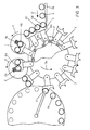
- a device comprises a first for processing the edges of cans 4 formed processing station 1 and a second for trimming the edges of cans 4 formed processing station 2.
- the can 4b to be processed by the first processing station 1 is shown in FIG FIG. 1 shown operating state on a located in the center of a cutting device mandrel 11 (FIG. FIG. 4 ) postponed. It is fixed in position by means of a clamping jaw 1a, so that it can be trimmed at the edge by means of the cutting device.
- the can 4a to be processed by the second processing station 2 is immobilized by means of a second clamping jaw 2a on a mandrel 12 located in the center of a cutting device (FIG. FIG. 4 ) fixed.
- the for fixing the cans 4b, 4a required movement of the jaws 1a, 2a is in FIG. 1 indicated by arrows 1a ', 2a'.
- the cans 4, 4a, 4b are arranged in receptacles 5, which each have two shells, so that they can receive two cans at a time.
- the receivers 5 are fastened to a first lever arm 6a of a two-armed lever 6a, 6b pivotable about a pivot axis 6c.
- rollers 6d are arranged, which roll on the edge of a cam 7.
- the drive of the cam 7 is effected by means of a servomotor, not shown in the figure.
- a corresponding restoring force is exerted on the first lever arm 6a and / or the second lever arm 6b by means of a spring, not shown in the figure.
- a three-armed lever can be used instead of a two-armed lever.
- the third lever follows a corresponding course of another cam.
- the levers 6a, 6b are arranged pivotably on a trimming gear 3 rotatable about an axis 3c.
- the direction of rotation of the trimming gear 3, which is at the same time the transport direction of the cans 4 and the receptacles 5, is in FIG. 1 represented by an arrow 3a.
- the rotation of the trimming gear 3 about the rotation axis 3c is carried out stepwise in a machining cycle. Since eleven levers 6a, 6b are disposed on the trimming gear 3, the pitch 3b is about 32.73 degrees.
- the drive of the Beschneidegetriebes 3 also takes place by means of a servomotor not shown in the figure.
- a removal unit designed as a drum 8 is arranged behind the second processing station 2.
- the drum 8 has mandrels 9, on which cans 4 can be applied.
- the application of the cans 4 on the mandrels 9 is done by means of a slide 8a, by means of which the cans 4 are pushed by the relevant shell of the receptacles 5 on the mandrels 9.
- operating state is located in the direction of rotation 3a of the trimming gear 3 front shell 5a of the respective receptacle 5 relative to a mandrel 9 of the drum 8, so that the relevant can 4e can be pushed by the slider 8a on the mandrel 9.
- the cutting devices of the two processing stations 1, 2 begin their operation, that is, crop the edges of the cans 4b, 4a located in the cutting devices. This is indicated by the arrows 1 ', 2'.
- the cam 7 rotates in the direction indicated by the arrow 7 'direction.
- the respective lever arms 6a and thus the associated seats 5 are pivoted in the directions indicated by the arrows 6c ', 6c ", at the same time the drum 8 rotates in the direction indicated by the arrow 8' the device is located in the in FIG. 3 shown operating state.
- rear shell 5b arranged in front of the inclined plane 10 receptacle 5 is in a position such that it can be equipped with a can 4d. Furthermore, in the direction of rotation 3 'of the trimming gear 3, the rear shell 5b of the receptacle 5 arranged in front of the drum 8 is located in front of a mandrel 9 of the drum 8.
- the clamping of the cans 4a, 4b is lifted by means of the jaws 1a, 2a. That is, the jaws 1a, 2a are in the by the arrows 1a ", 2a" ( FIG. 4 ) indicated direction adjusted.
- the trimming gear 3 is adjusted by one step. The adjustment of the trimming mechanism 3 is indicated by an arrow 3 'in FIG. 4 indicated.
- the cam 7 is adjusted in the direction indicated by the arrow 7. Since the trimming gear 3 and the cam 7 rotate simultaneously, no relative movement takes place between the two elements Pivoting movement through.
- the drum 8 performs a step in the direction indicated by the arrow 8 'direction.
- the device is again in the in FIG. 1 shown operating state. That is, the front in the direction of rotation 3a of 3 Beschneidegetriebes 3 shell 5a then arranged in front of the inclined plane 10 receptacle 5 is in a position such that it can be equipped with a can 4 c. Furthermore, in the direction of rotation 3a of the trimming gear 3 rear shell 5b of the respective receptacle 5 is in a position such that the relevant can 4b can be pushed onto the mandrel 11.
Abstract
Description
Die Erfindung betrifft eine Vorrichtung nach dem Oberbegriff des Anspruchs 1, zur Bearbeitung von Werkstücken, mit wenigstens einer ersten Bearbeitungsstation, in der die Werkstücke während einer Arbeitsphase eines aus der Arbeitsphase und einer Transportphase bestehenden Bearbeitungstaktes bearbeitbar sind, und einer Transporteinheit, die erste Aufnahmen für die Werkstücke aufweist, und mittels der die Werkstücke der ersten Bearbeitungsstation während der Transportphase durch Transport in eine Transportrichtung zuführbar sind.The invention relates to a device according to the preamble of
Eine derartige Vorrichtung wird beispielsweise von der Patentanmelderin seit vielen Jahren hergestellt und vertrieben. Bei der bekannten Vorrichtung werden Metalldosen mittels einer als Trommel ausgebildeten Transporteinheit einer Bearbeitungsstation zugeführt, in der die Ränder der Dosen beschnitten werden. Nachdem der Rand einer Dose beschnitten ist, wird die betreffende Dose an eine Abnahmeeinheit übergeben, mittels der die Dosen an eine weitere Station zur weiteren Bearbeitung übergeben werden.Such a device is manufactured and sold for example by the patent applicant for many years. In the known device metal cans are fed by means of a transport unit designed as a drum of a processing station, in which the edges of the cans are cut. After the edge of a can is cropped, the can in question is handed over to a pickup unit, by means of which the cans are transferred to another station for further processing.
Da die Beschneidung der Dosenränder relativ viel Zeit in Anspruch nimmt und während dieser Zeit von der Vorrichtung keine sonstigen Aktionen durchgeführt werden können, wird der Durchsatz der Vorrichtung von der Bearbeitungsstation vorgegeben. Das heißt der Durchsatz der Vorrichtung wird durch die Zeit, die zum Beschneiden der Dosenränder benötigt wird, begrenzt. Da das Beschneiden der Dosenränder relativ lange dauert, ist der Durchsatz der Vorrichtung entsprechend gering.Since the circumcision of the can edges takes a relatively long time and during this time of the device can be performed no other actions, the throughput of the device is specified by the processing station. That is, the throughput of the device is limited by the time required to trim the can edges. Since the trimming of the can edges takes a relatively long time, the throughput of the device is correspondingly low.
Es ist Aufgabe der Erfindung, eine Eingangs genannte Vorrichtung derart auszubilden, dass sie einen höheren Durchsatz hat.It is an object of the invention to form an input called device such that it has a higher throughput.
Die Lösung dieser Aufgabe ergibt sich aus den Merkmalen des kennzeichnenden Teils des Anspruchs 1. Vorteilhafte Weiterbildungen der Erfindung ergeben sich aus den Unteransprüchen.The solution of this problem arises from the features of the characterizing part of
Gemäß der Erfindung ist eine Vorrichtung zur Bearbeitung von Werkstücken, mit wenigstens einer ersten Bearbeitungsstation, in der die Werkstücke während einer Arbeitsphase eines aus der Arbeitsphase und einer Transportphase bestehenden Bearbeitungstaktes bearbeitbar sind, und einer Transporteinheit, die erste Aufnahmen für die Werkstücke aufweist, und mittels der die Werkstücke der ersten Bearbeitungsstation während der Transportphase durch Transport in eine Transportrichtung zuführbar sind, dadurch gekennzeichnet, dass in Transportrichtung hinter der ersten Bearbeitungsstation wenigstens eine zweite Bearbeitungsstation angeordnet ist, und die ersten Aufnahmen verstellbar an der Transporteinheit angeordnet sind.According to the invention, a device for machining workpieces, with at least a first processing station, in which the workpieces are machinable during a working phase of an existing from the working phase and a transport phase machining cycle, and a transport unit having first receptacles for the workpieces, and means the workpieces of the first processing station can be fed by transport in a transport direction during the transport phase, characterized in that in the transport direction behind the first processing station at least a second processing station is arranged, and the first recordings are arranged adjustably on the transport unit.
Dadurch, dass in Transportrichtung hinter der ersten Bearbeitungsstation wenigstens eine zweite Bearbeitungsstation, die regelmäßig dieselbe Bearbeitung vornimmt wie die erste Bearbeitungsstation, angeordnet ist, lässt sich der Durchsatz der Vorrichtung erhöhen. Denn dadurch, dass in Transportrichtung hinter der ersten Bearbeitungsstation wenigstens eine zweite Bearbeitungsstation angeordnet ist, lassen sich wenigstens zwei Werkstücke gleichzeitig bearbeiten. Dadurch, dass die ersten Aufnahmen verstellbar an der Transporteinheit angeordnet sind, insbesondere in und/oder gegen die Transportrichtung verschwenk- und/oder verschiebbar an der Transporteinheit angeordnet sind, lässt sich erreichen, dass die ersten Aufnahmen in einem Takt verstellt werden, dessen Frequenz größer ist, als die Frequenz des Bearbeitungstaktes. So lassen sich beispielsweise während des Bearbeitungstaktes ein oder mehrere Zwischentakte zum Verstellen der ersten Aufnahmen einfügen. Hierdurch erhöht sich der Bestückungstakt, in dem der Vorrichtung Werkstücke zugeführt werden, deutlich.Characterized in that in the transport direction behind the first processing station at least a second processing station that regularly performs the same processing as the first processing station is arranged, the throughput of the device can be increased. Because the fact that at least one second processing station is arranged in the transport direction behind the first processing station, at least two workpieces can be processed simultaneously. The fact that the first recordings are arranged adjustably on the transport unit, in particular in and / or against the transport direction pivotable and / or slidably disposed on the transport unit, can be achieved that the first recordings are adjusted in one cycle whose frequency is greater is, as the frequency of the processing cycle. Thus, for example, one or more intermediate clocks for adjusting the first recordings can be inserted during the processing cycle. As a result, the loading cycle, in which the device workpieces are supplied, significantly.
Um im Falle von zwei Bearbeitungsstationen beide Bearbeitungsstationen im Bearbeitungstakt der Vorrichtung mit Werkstücken versorgen zu können, sind die ersten Aufnahmen vorzugsweise derart ausgebildet, dass sie zwei Werkstücke gleichzeitig aufnehmen können. Sofern mehr als zwei Bearbeitungsstationen hintereinander angeordnet sind, müssen von den ersten Aufnahmen entsprechend viele Werkstücke aufnehmbar sein. Somit werden im Bearbeitungstakt der Vorrichtung entsprechend der Anzahl der Werkstücke, die in einer ersten Aufnahme angeordnet sind, gleichzeitig wenigstens zwei oder gegebenenfalls mehrere Werkstücke mittels der Transporteinheit durch die Vorrichtung transportiert. Entsprechend der Anzahl der Werkstücke, die gleichzeitig durch die Vorrichtung transportiert werden, erhöht sich der Bestückungstakt der Vorrichtung.In order to be able to supply both processing stations in the processing cycle of the device with workpieces in the case of two processing stations, the first receptacles are preferably designed such that they can accommodate two workpieces at the same time. If more than two processing stations are arranged one behind the other, correspondingly many workpieces must be receivable from the first receptacles. Thus, at least two or optionally several workpieces are simultaneously transported through the device in the processing cycle of the device according to the number of workpieces arranged in a first receptacle by means of the transport unit. According to the number of workpieces that are transported simultaneously through the device, the loading cycle of the device increases.
Mit anderen Worten, dadurch, dass der Takt in dem die ersten Aufnahmen verstellbar sind, größer ist, als der Bearbeitungstakt, in dem die Transporteinheit verstellbar ist, lassen sich die ersten Aufnahmen beziehungsweise lässt sich die Transporteinheit mit Werkstücken in einem Takt bestücken, der einem vielfachen, beispielsweise dem doppelten des Bearbeitungstaktes entspricht.In other words, by the fact that the clock in which the first recordings are adjustable, is greater than the processing cycle in which the transport unit is adjustable, the first recordings or can be the transport unit with workpieces in one cycle populate the one multiples, for example, twice the processing clock corresponds.
Dies wird dadurch erreicht, dass durch die Verstellung, insbesondere durch die Verschwenkung und/oder Verschiebung der ersten Aufnahmen während der Bearbeitung der Werkstücke in den Bearbeitungsstationen, das heißt, während der Arbeitsphase des Bearbeitungstaktes ein Zwischentakt erzeugt wird beziehungsweise im Falle von mehr als zwei Bearbeitungsstationen mehrere Zwischentakte erzeugt werden. Mit anderen Worten, während die Transporteinheit keine Bewegung ausführt, wird gemäß einer besonderen Ausführungsform der Erfindung diejenige erste Aufnahme, der Werkstücke zugeführt werden sollen, verschwenkt und/oder verschoben, wodurch ein Zwischentakt erzeugt wird.This is achieved in that by the adjustment, in particular by the pivoting and / or displacement of the first recordings during processing of the workpieces in the processing stations, that is, during the working phase of the processing cycle an intermediate clock is generated or in the case of more than two processing stations several intermediate cycles are generated. In other words, while the transport unit is not performing any movement, according to a particular embodiment of the invention, the first receptacle to be supplied with workpieces is pivoted and / or displaced, whereby an intermediate cycle is generated.
Zur Verdeutlichung der Funktionsweise wird nachfolgend die Zuführung von Werkstücken, mit denen die Transporteinheit in einem Bestückungstakt bestückt wird, an zwei Bearbeitungsstationen näher beschrieben.In order to clarify the mode of operation, the supply of workpieces with which the transport unit is equipped in one insertion cycle will be described below in more detail at two processing stations.
Nachdem die Transporteinheit einen Transportschritt durchgeführt hat, befindet sich eine betreffende erste Aufnahme in einer Position, in der sie mit einem ersten Werkstück bestückt werden kann. Nachdem sich das erste Werkstück in der ersten Aufnahme befindet, wird die erste Aufnahme in Transportrichtung der Zuführeinheit derart verstellt, dass sie mit einem zweiten Werkstück bestückt werden kann. Letzteres geschieht etwa in der Mitte der Arbeitsphase.After the transport unit has carried out a transport step, a respective first receptacle is in a position in which it can be equipped with a first workpiece. After the first workpiece is in the first recording, the first recording in the transport direction of the feed unit is adjusted so that it can be equipped with a second workpiece. The latter happens approximately in the middle of the work phase.
Nachdem sich das zweite Werkstück in der ersten Aufnahme befindet, was etwa am Ende der Arbeitsphase der Fall ist, wird die Transporteinheit um einen Transportschritt verstellt, sodass die erste Aufnahme, in der sich die beiden Werkstücke befinden, in eine Position gelangt, in der die Werkstücke an die beiden Bearbeitungsstationen abgegeben werden können beziehungsweise gleichzeitig von den beiden Bearbeitungsstationen bearbeitet werden können.After the second workpiece is in the first receptacle, which is the case at the end of the working phase, the transport unit is moved by a transport step, so that the first receptacle in which the two workpieces are located in a position in which the Workpieces can be delivered to the two processing stations or can be processed simultaneously by the two processing stations.
Durch die Verstellung der Transporteinheit um einen Transportschritt gelangt die nachfolgende erste Aufnahme in die Position, in der sie mit einem ersten Werkstück bestückt werden kann. Somit kann während der Bearbeitung der Werkstücke die nachfolgende erste Aufnahme in der zuvor beschriebenen Weise mit Werkstücken bestückt werden.By adjusting the transport unit to a transport step, the subsequent first recording reaches the position in which it can be equipped with a first workpiece. Thus, during the processing of the workpieces, the subsequent first receptacle can be equipped with workpieces in the manner described above.
In gleicher Weise können der vorhergehenden ersten Aufnahme, das heißt der ersten Aufnahme, deren Werkstücke bereits in den Bearbeitungsstationen bearbeitet wurden, die sich in ihr befindenden Werkstücke entnommen werden. Das heißt, nach Durchführung eines Transportschritts der Transporteinheit befindet sich die vorhergehende erste Aufnahme in einer Position, in der ihr ein Werkstück entnommen werden kann. Nachdem der ersten Aufnahme das Werkstück entnommen wurde, was etwa in der Mitte einer Arbeitsphase der Fall ist, wird die erste Aufnahme verschwenkt und/oder verschoben, so dass sie sich in einer Position befindet, in der ihr das zweite Werkstück entnommen werden kann. Somit erhöht sich der Abgabetakt, das heißt der Takt, in dem die Vorrichtung Werkstücke abgibt, in gleicher Weise wie der Bestückungstakt, deutlich.In the same way, the preceding first receptacle, that is to say the first receptacle whose workpieces have already been processed in the processing stations, can be removed from the workpieces located in it. That is, after performing a transporting step of the transport unit, the previous first pickup is in a position where a work can be taken out of it. After the first shot the workpiece is removed was, which is the case about in the middle of a working phase, the first recording is pivoted and / or moved so that it is in a position in which it can be removed from the second workpiece. Thus, the discharge cycle, that is the cycle in which the device delivers workpieces, increases significantly in the same way as the loading cycle.
Aus konstruktiven Gründen kann es erforderlich sein, die Bearbeitungsstationen in einem solchen Abstand hintereinander anzuordnen, der es nicht mehr gestattet, dass Werkstücke, die sich in ein und derselben ersten Aufnahme befinden, gleichzeitig bearbeitet werden können. Daher ist bei einer besonderen Ausführungsform der Erfindung vorgesehen, dass die zweite Bearbeitungsstation in einem solchen Abstand hinter der ersten Bearbeitungsstation angeordnet ist, der einem Transportschritt zuzüglich des Abstands, in dem die Werkstücke in der ersten Aufnahme angeordnet sind, entspricht.For design reasons, it may be necessary to arrange the processing stations in such a distance one behind the other, which no longer allows that workpieces that are in one and the same first recording, can be processed simultaneously. Therefore, it is provided in a particular embodiment of the invention that the second processing station is arranged at such a distance behind the first processing station, which corresponds to a transport step plus the distance in which the workpieces are arranged in the first receptacle.
Hierdurch ist es möglich, in der ersten Bearbeitungsstation zunächst das der ersten Aufnahme als zweites zugeführte Werkstück, welches in Transportrichtung hinter dem der ersten Aufnahme als erstes zugefügte Werkstück angeordnet ist, zu bearbeiten und, nachdem die Transporteinheit einen Transportschritt durchgeführt hat, in der zweiten Bearbeitungsstation das der ersten Aufnahme als erstes zugeführte Werkstück, welches in Transportrichtung vor dem der ersten Aufnahme als zweites zugefügte Werkstück angeordnet ist, zu bearbeiten.This makes it possible, in the first processing station, first of all to process the first pickup as the second fed workpiece, which is arranged behind the first pickup as the first feed added in the transport direction, and, after the transport unit has carried out a transporting step, in the second workstation to process the first pickup as the first supplied workpiece, which is arranged in the transport direction before the first pickup as a second added workpiece.
Sollte es erforderlich sein, dass die zweite Bearbeitungsstation nicht in einem solchen Abstand hinter der ersten Bearbeitungsstation angeordnet wird, der einem Transportschritt zuzüglich des Abstands, in dem die Werkstücke in der ersten Aufnahme angeordnet sind, entspricht, sondern um einen Differenzabstand mehr oder weniger, so kann dieser Differenzabstand durch eine entsprechende Verstellung der betreffenden ersten Aufnahme korrigiert werden. Daher ist bei einer besonderen Ausführungsform der Erfindung vorgesehen, dass der zuzügliche Abstand, um den der Weg, den die ersten Aufnahmen während eines Transportschrittes zurücklegen, ergänzt wird, um einen Korrekturwert verändert ist.Should it be necessary that the second processing station is not arranged at such a distance behind the first processing station, which corresponds to a transport step plus the distance in which the workpieces are arranged in the first receptacle, but by a difference distance more or less, so This difference distance can be corrected by a corresponding adjustment of the relevant first recording. Therefore, it is provided in a particular embodiment of the invention that the additional Distance by which the path taken by the first images during a transport step is supplemented by a correction value.
Bei einer weiteren besonderen Ausführungsform der Erfindung ist vorgesehen, dass die Transporteinheit einen Revolverkopf aufweist, der im Bearbeitungstakt jeweils um einen Winkel verstellbar ist. Hierdurch lassen sich den Bearbeitungsstationen auf einfache Weise und in kompakter Bauform Werkstücke zuführen.In a further particular embodiment of the invention it is provided that the transport unit has a turret, which is adjustable in the processing cycle in each case by an angle. This allows the processing stations to perform workpieces in a simple manner and in a compact design.
Des Weiteren lässt sich auf einfache Weise eine präzise Verstellung der Aufnahmen erreichen. So können die ersten Aufnahmen jeweils an einem Hebelarm angeordnet sein, der um eine Schwenkachse schwenkbar mit dem Revolverkopf verbunden ist, wie dies bei einer weiteren besonderen Ausführungsform der Erfindung vorgesehen ist. Die Hebelarme lassen sich zur Erzeugung einer Schwenkbewegung auf einfache Weise mit einem Antrieb verbinden.Furthermore, a precise adjustment of the recordings can be achieved in a simple manner. Thus, the first receptacles may each be arranged on a lever arm, which is connected pivotably about a pivot axis with the turret, as provided in a further particular embodiment of the invention. The lever arms can be easily connected to a drive for generating a pivoting movement.
In vorteilhafter Weise ist der Hebelarm Teil eines mehrarmigen Hebels, wodurch der Antrieb mittels einer Kurvenscheibe vorgenommen werden kann. Hierzu muss derjenige Arm des Hebels, der bezüglich der Schwenkachse des Hebels jenseits der ersten Aufnahmen angeordnet ist, mit der Kurvenscheibe in Wirkverbindung stehen. Durch die Kurvenscheibe ist es möglich, gleichzeitig mehrere Hebel und damit die an den betreffenden Hebelarmen angeordneten ersten Aufnahmen zu verstellen. Statt die Hebelarme mittels einer Kurvenscheibe anzutreiben könnten sie auch direkt mittels Servomotoren oder pneumatischer beziehungsweise hydraulischer Antriebe angetrieben werden.Advantageously, the lever arm is part of a multi-arm lever, whereby the drive can be made by means of a cam. For this purpose, that arm of the lever, which is arranged with respect to the pivot axis of the lever on the other side of the first receptacles, must be in operative connection with the cam disk. Through the cam, it is possible to simultaneously adjust several levers and thus arranged on the respective lever arms first recordings. Instead of driving the lever arms by means of a cam, they could also be driven directly by means of servomotors or pneumatic or hydraulic drives.
Bei einer weiteren besonderen Ausführungsform der Erfindung ist in Transportrichtung hinter der zweiten Bearbeitungsstation eine Abnahmeeinheit angeordnet, welche zweite Aufnahmen aufweist, welche im Abgabetakt der Vorrichtung verstellbar sind. In vorteilhafter Weise entspricht der Abgabetakt einem ganzzahligen Vielfachen des Bearbeitungstaktes. Die Werkstücke werden der Transporteinheit in der oben bereits beschriebenen Weise entnommen.In a further particular embodiment of the invention, a removal unit is arranged in the transport direction behind the second processing station, which has second receptacles, which are adjustable in the discharge cycle of the device. Advantageously, the output clock corresponds to an integer Multiples of the processing cycle. The workpieces are removed from the transport unit in the manner already described above.
Weitere Einzelheiten, Merkmale und Vorteile der vorliegenden Erfindung ergeben sich aus der nachfolgenden Beschreibung eines besonderen Ausführungsbeispiels unter Bezugnahme auf die Zeichnung.Further details, features and advantages of the present invention will become apparent from the following description of a particular embodiment with reference to the drawings.
Es zeigt:
- Fig. 1
- eine schematische Darstellung einer erfindungsgemäßen Vorrichtung in einem ersten Betriebszustand,
- Fig. 2
- eine schematische Darstellung einer erfindungsgemäßen Vorrichtung in einem zweiten Betriebszustand,
- Fig. 3
- eine schematische Darstellung einer erfindungsgemäßen Vorrichtung in einem dritten Betriebszustand und
- Fig. 4
- eine schematische Darstellung einer erfindungsgemäßen Vorrichtung in einem vierten Betriebszustand,
- Fig. 1
- a schematic representation of a device according to the invention in a first operating state,
- Fig. 2
- a schematic representation of a device according to the invention in a second operating state,
- Fig. 3
- a schematic representation of a device according to the invention in a third operating state and
- Fig. 4
- a schematic representation of a device according to the invention in a fourth operating state,
Wie beispielsweise
Die Dosen 4, 4a, 4b sind in Aufnahmen 5 angeordnet, welche jeweils zwei Schalen haben, so dass sie jeweils zwei Dosen gleichzeitig aufnehmen können. Die Aufnahmen 5 sind an einem ersten Hebelarm 6a eines um eine Schwenkachse 6c schwenkbaren zweiarmigen Hebels 6a, 6b befestigt.The
An dem zweiten Hebelarm 6b des Hebels 6a, 6b, der bezüglich der Schwenkachse 6c jenseits der ersten Aufnahmen 5 angeordnet ist, sind Rollen 6d angeordnet, welche auf dem Rand einer Kurvenscheibe 7 abrollen. Der Antrieb der Kurvenscheibe 7 erfolgt mittels eines in der Figur nicht dargestellten Servomotors.On the
Damit die Rollen 6d dem Rand der Kurvenscheibe 7 auch in Richtung zum Drehpunkt der Kurvenscheibe 7 folgen, wird auf den ersten Hebelarm 6a und/oder den zweiten Hebelarm 6b mittels einer in der Figur nicht dargestellten Feder eine entsprechende Rückstellkraft ausgeübt. Statt die Rückstellkraft mittels einer Feder zu erzeugen, kann statt eines zweiarmigen Hebels ein dreiarmiger Hebel verwendet werden. Hierbei folgt der dritte Hebel einem entsprechenden Verlauf einer weiteren Kurvenscheibe.So that the
Die Hebel 6a, 6b sind an einem um eine Achse 3c drehbaren Beschneidegetriebe 3 schwenkbar angeordnet. Die Drehrichtung des Beschneidegetriebes 3, die gleichzeitig die Transportrichtung der Dosen 4 beziehungsweise der Aufnahmen 5 ist, ist in
Die Drehung des Beschneidegetriebes 3 um die Drehachse 3c erfolgt schrittweise in einem Bearbeitungstakt. Da an dem Beschneidegetriebe 3 elf Hebel 6a, 6b angeordnet sind, beträgt die Schrittweite 3b etwa 32,73 Grad. Der Antrieb des Beschneidegetriebes 3 erfolgt ebenfalls mittels eines in der Figur nicht dargestellten Servomotors.The rotation of the
Die Bestückung der Aufnahmen 5 mit Dosen 4 erfolgt mittels einer schiefen Ebene 10, auf der die Dosen 4 in die durch einen Pfeil 4' angedeutete Richtung abrollen. In dem in
In Drehrichtung 3a des Beschneidegetriebes 3 ist hinter der zweiten Bearbeitungsstation 2 eine als Trommel 8 ausgebildete Abnahmeeinheit angeordnet. Die Trommel 8 hat Dorne 9, auf welche Dosen 4 aufbringbar sind. Die Aufbringung der Dosen 4 auf die Dorne 9 geschieht mittels eines Schiebers 8a, mittels dem die Dosen 4 von der betreffenden Schale der Aufnahmen 5 auf die Dorne 9 geschoben werden.In the direction of
In dem in
Nachdem die Klemmbacken 1a, 2a die durch die Pfeile 1a', 2a' angedeutete Bewegung durchgeführt haben, das heißt die betreffenden Dosen 4a, 4b fixiert sind, und die auf der schiefen Ebene 10 angeordnete Dosen 4 die durch den Pfeil 4' angedeutete Bewegung durchgeführt haben, das heißt sich die vordere Dose 4c in der Schale 5a der betreffenden Aufnahme 5 befindet, sowie der Schieber 8a die betreffende Dose 4e auf den Dorn 9 der Trommel 8 geschoben hat, beginnt der in
Das heißt, die Schneidevorrichtungen der beiden Bearbeitungsstationen 1, 2 beginnen ihre Tätigkeit, das heißt beschneiden die Ränder der sich in den Schneidevorrichtungen befindlichen Dosen 4b, 4a. Dies ist durch die Pfeile 1', 2' angedeutet. Gleichzeitig dreht sich die Kurvenscheibe 7 in die durch den Pfeil 7' angedeutete Richtung. Hierdurch werden im Ergebnis die betreffenden Hebelarme 6a und damit die zugehörigen Aufnahmen 5 in die durch die Pfeile 6c', 6c" angedeutete Richtungen verschwenkt. Gleichzeitig dreht sich die Trommel 8 in die durch den Pfeil 8' angedeutete Richtung. Nach Abschluss der vorstehend genannten Bewegungen befindet sich die Vorrichtung in dem in
Das heißt, die in Drehrichtung 3' des Beschneidegetriebes 3 hintere Schale 5b der vor der schiefen Ebene 10 angeordneten Aufnahme 5 befindet sich in einer solchen Position, dass sie mit einer Dose 4d bestückt werden kann. Des Weiteren befindet sich die in Drehrichtung 3' des Beschneidegetriebes 3 hintere Schale 5b der vor der Trommel 8 angeordneten Aufnahme 5 vor einem Dorn 9 der Trommel 8.That is, in the direction of rotation 3 'of the
Nachdem sich die Dose 4d in der hinteren Schale 5b der vor der schiefen Ebene 10 angeordneten Aufnahme 5 befindet und die vor der Trommel 8 angeordnete Dose 4f mittels des Schiebers 8a auf den betreffenden Dorn 9 der Trommel 8 geschoben wurde, sowie die Ränder der in den Bearbeitungsstationen 1, 2 angeordneten Dosen 4a, 4b beschnitten wurden, wird die Klemmung der Dosen 4a, 4b mittels der Klemmbacken 1a, 2a aufgehoben. Das heißt, die Klemmbacken 1a, 2a werden in die durch die Pfeile 1a", 2a" (
Gleichzeitig mit der Verstellung des Beschneidegetriebes 3 wird die Kurvenscheibe 7 in die durch den Pfeil 7" angedeutete Richtung verstellt. Da sich das Beschneidegetriebe 3 und die Kurvenscheibe 7 gleichzeitig drehen, findet zwischen den beiden Elementen keine Relativbewegung statt. Hierdurch führen die betreffenden Hebelarme 6a keine Schwenkbewegung durch.Simultaneously with the adjustment of the
Des Weiteren führt die Trommel 8 einen Schritt in die durch den Pfeil 8' angedeutete Richtung durch. Nach Abschluss der vorstehend genannten Bewegungen befindet sich die Vorrichtung wieder in dem in
Dann werden die in den Bearbeitungsstationen 1,2 angeordneten Dosen 4a, 4b mittels der Klemmbacken 1a, 2a fixiert und der zuvor beschriebene Vorgang beginnt aufs Neue.Then arranged in the processing stations 1.2
Claims (10)
dass in Transportrichtung (3a) hinter der ersten Bearbeitungsstation (1) in einem Abstand wenigstens eine zweite Bearbeitungsstation (2) angeordnet ist, und die ersten Aufnahmen (5) verstellbar an der Transporteinheit (3) angeordnet sind.Device for processing workpieces (4), with at least one first processing station (1) in which the workpieces (4) can be processed during a working phase of a processing cycle consisting of the working phase and a transport phase, and a transport unit (3), the first receptacles (5) for the workpieces (4), and by means of which the workpieces (4) of the first processing station (1) can be fed during transport through transport in a transport direction (3a), characterized
that in the transport direction (3a) behind the first processing station (1) at a distance at least one second processing station (2) is arranged, and the first receptacles (5) are adjustably arranged on the transport unit (3).
dadurch gekennzeichnet,
dass die Verstellung der ersten Aufnahmen (5) während der Arbeitsphase erfolgt.Device according to claim 1,
characterized,
that the adjustment of the first recordings (5) takes place during the working phase.
dadurch gekennzeichnet,
dass der Abstand, in dem die zweite Bearbeitungsstation (2) hinter der ersten Bearbeitungsstation (1) angeordnet ist, dem Weg entspricht, den die ersten Aufnahmen (5) während eines Transportschrittes zurücklegen, zuzüglich dem Abstand, in dem die Werkstücke (4) in den Aufnahmen (5) angeordnet sind.Apparatus according to claim 1 or 2,
characterized,
that the distance in which the second processing station (2) is arranged behind the first processing station (1) corresponds to the distance traveled by the first receptacles (5) during a transporting step plus the distance in which the workpieces (4) engage in the recordings (5) are arranged.
dadurch gekennzeichnet,
dass der zuzügliche Abstand, um den der Weg, den die ersten Aufnahmen (5) während eines Transportschrittes zurücklegen, ergänzt wird, um einen Korrekturwert verändert ist.Device according to claim 3,
characterized,
that the additional distance by which the path taken by the first exposures (5) during a transport step is supplemented by a correction value has changed.
dadurch gekennzeichnet,
dass die Transporteinheit einen Revolverkopf (3) aufweist, der im Bearbeitungstakt jeweils um einen Winkel (3b) verstellbar ist.Device according to one of claims 1 to 4,
characterized,
that the transport unit comprises a turret (3), the processing cycle in each case by an angle (3b) is adjustable.
dadurch gekennzeichnet,
dass die ersten Aufnahmen (5) jeweils an einem Hebelarm (6a) angeordnet sind, der um eine Schwenkachse (6c) schwenkbar mit dem Revolverkopf (3) verbunden ist.Device according to claim 5,
characterized,
that said first receptacles (5) in each case on a lever arm (6a) are disposed about a swivel axis (6c) pivotally connected to the turret (3).
dadurch gekennzeichnet,
dass der Hebelarm (6a) mit einem Antrieb (7) verbunden ist, zur Erzeugung einer Schwenkbewegung.Device according to claim 6,
characterized,
in that the lever arm (6a) is connected to a drive (7) for generating a pivoting movement.
dadurch gekennzeichnet,
dass der Hebelarm (6a) Teil eines wenigstens zweiarmigen Hebels (6a, 6b) ist, und der Antrieb (7) eine Kurvenscheibe (7) aufweist, mit der derjenige Arm (6b) des Hebels (6a, 6b), der bezüglich der Schwenkachse (6c) des Hebels (6a, 6b) jenseits der ersten Aufnahmen (5) angeordnet ist, in Wirkverbindung steht.Device according to claim 7,
characterized,
in that the lever arm (6a) is part of an at least two-armed lever (6a, 6b), and the drive (7) has a cam disc (7), with which the arm (6b) of the lever (6a, 6b), with respect to the pivot axis (6c) of the lever (6a, 6b) is arranged beyond the first receptacles (5) is in operative connection.
dadurch gekennzeichnet,
dass in Transportrichtung (3a) hinter der zweiten Bearbeitungsstation (2) eine Abnahmeeinheit (8) angeordnet ist, welche zweite Aufnahmen (9) aufweist, welche in einem Abnahmetakt verstellbar sind.Device according to one of claims 1 to 8,
characterized,
that in the transport direction (3a) behind the second processing station (2) a decrease unit (8) is arranged, which has second receptacles (9) which are adjustable in a take-off cycle.
dadurch gekennzeichnet,
dass der Abnahmetakt einem ganzzahligen Vielfachen des Bearbeitungstaktes entspricht.Device according to claim 9,
characterized,
that the acceptance clock corresponds to an integer multiple of the processing cycle.
Applications Claiming Priority (1)
| Application Number | Priority Date | Filing Date | Title |
|---|---|---|---|
| DE102010033749A DE102010033749B4 (en) | 2010-08-07 | 2010-08-07 | Device for processing workpieces |
Publications (2)
| Publication Number | Publication Date |
|---|---|
| EP2415538A1 true EP2415538A1 (en) | 2012-02-08 |
| EP2415538B1 EP2415538B1 (en) | 2013-08-28 |
Family
ID=44644868
Family Applications (1)
| Application Number | Title | Priority Date | Filing Date |
|---|---|---|---|
| EP11006363.3A Active EP2415538B1 (en) | 2010-08-07 | 2011-08-03 | Device for processing workpieces |
Country Status (4)
| Country | Link |
|---|---|
| US (1) | US8739959B2 (en) |
| EP (1) | EP2415538B1 (en) |
| BR (1) | BRPI1103872A2 (en) |
| DE (1) | DE102010033749B4 (en) |
Cited By (1)
| Publication number | Priority date | Publication date | Assignee | Title |
|---|---|---|---|---|
| WO2014195447A1 (en) * | 2013-06-07 | 2014-12-11 | Bausch + Ströbel Maschinenfabrik Ilshofen GmbH + Co. KG | Transfer apparatus |
Families Citing this family (8)
| Publication number | Priority date | Publication date | Assignee | Title |
|---|---|---|---|---|
| DE102012212206A1 (en) * | 2012-07-12 | 2014-01-16 | Siemens Aktiengesellschaft | Turntable, circular table, mounting system and operating procedures |
| EP2840046B1 (en) * | 2013-08-23 | 2017-02-01 | HINTERKOPF GmbH | Conveying device, machining system and method for conveying and machining a workpiece |
| DE102014106573A1 (en) * | 2014-05-09 | 2015-11-12 | Khs Gmbh | Holding and centering device, container treatment device and method for treating containers |
| DE102015010004A1 (en) * | 2015-07-31 | 2017-02-02 | Vollmer Werke Maschinenfabrik Gmbh | Device for processing workpieces, in particular saw blades |
| US11535450B1 (en) | 2019-12-04 | 2022-12-27 | Amazon Technologies, Inc. | Item loading by chamber bounded by synchronized conveying surfaces |
| US11584593B1 (en) * | 2020-03-26 | 2023-02-21 | Amazon Technologies, Inc. | Automatic rotary inserting machine |
| IT202000018790A1 (en) * | 2020-07-31 | 2022-01-31 | Gd Spa | ITEMS HANDLING UNIT |
| CN114850529B (en) * | 2022-07-06 | 2022-09-20 | 靖江市苏伦工程机械有限公司 | Intelligent control drilling machine for pin shaft machining |
Citations (3)
| Publication number | Priority date | Publication date | Assignee | Title |
|---|---|---|---|---|
| DE3908394C1 (en) * | 1989-03-15 | 1989-12-21 | Karges-Hammer-Maschinen Gmbh & Co Kg, 3300 Braunschweig, De | Apparatus for making can bodies |
| EP1060831A1 (en) * | 1999-06-18 | 2000-12-20 | Société pour Faciliter les Operations Mecaniques (S.F.O.M.) S.R.L. | Workpiece transfer device |
| DE102009010280A1 (en) * | 2008-02-27 | 2009-10-08 | GM Global Technology Operations, Inc., Detroit | Mechanical processing station sub-carrier hoist |
Family Cites Families (7)
| Publication number | Priority date | Publication date | Assignee | Title |
|---|---|---|---|---|
| DE2742693C2 (en) * | 1977-09-22 | 1983-08-11 | Gildemeister Corpoplast Gmbh, 2000 Hamburg | Machine for blow molding hollow bodies, in particular bottles, made of thermoplastic material |
| DE19810238A1 (en) * | 1997-11-03 | 1999-05-06 | Krupp Corpoplast Masch | Preform transfer between heating and blowing wheels and transfer equipment for blow molding machine producing plastic containers |
| DE10325693B4 (en) * | 2002-10-25 | 2007-08-02 | Krones Ag | Transfer device for objects |
| DE102005002715A1 (en) * | 2005-01-20 | 2006-08-03 | Krones Ag | Method and device for holding vessels |
| FR2881677B1 (en) * | 2005-02-08 | 2007-04-27 | Sidel Sas | ROTARY DEVICE FOR TRANSFERRING CONTAINERS |
| DE102005056449A1 (en) * | 2005-11-26 | 2007-08-02 | Alfing Kessler Sondermaschinen Gmbh | Workpiece holding device and processing machine equipped therewith |
| CN101945727B (en) * | 2008-02-20 | 2012-09-05 | 平田机工株式会社 | Production apparatus |
-
2010
- 2010-08-07 DE DE102010033749A patent/DE102010033749B4/en not_active Expired - Fee Related
-
2011
- 2011-08-03 EP EP11006363.3A patent/EP2415538B1/en active Active
- 2011-08-05 BR BRPI1103872-1A patent/BRPI1103872A2/en not_active IP Right Cessation
- 2011-08-08 US US13/136,709 patent/US8739959B2/en not_active Expired - Fee Related
Patent Citations (3)
| Publication number | Priority date | Publication date | Assignee | Title |
|---|---|---|---|---|
| DE3908394C1 (en) * | 1989-03-15 | 1989-12-21 | Karges-Hammer-Maschinen Gmbh & Co Kg, 3300 Braunschweig, De | Apparatus for making can bodies |
| EP1060831A1 (en) * | 1999-06-18 | 2000-12-20 | Société pour Faciliter les Operations Mecaniques (S.F.O.M.) S.R.L. | Workpiece transfer device |
| DE102009010280A1 (en) * | 2008-02-27 | 2009-10-08 | GM Global Technology Operations, Inc., Detroit | Mechanical processing station sub-carrier hoist |
Cited By (1)
| Publication number | Priority date | Publication date | Assignee | Title |
|---|---|---|---|---|
| WO2014195447A1 (en) * | 2013-06-07 | 2014-12-11 | Bausch + Ströbel Maschinenfabrik Ilshofen GmbH + Co. KG | Transfer apparatus |
Also Published As
| Publication number | Publication date |
|---|---|
| DE102010033749A1 (en) | 2012-02-09 |
| EP2415538B1 (en) | 2013-08-28 |
| US8739959B2 (en) | 2014-06-03 |
| US20120031730A1 (en) | 2012-02-09 |
| BRPI1103872A2 (en) | 2013-04-16 |
| DE102010033749B4 (en) | 2012-02-16 |
Similar Documents
| Publication | Publication Date | Title |
|---|---|---|
| DE102010033749B4 (en) | Device for processing workpieces | |
| EP2144729B1 (en) | Device for and method of producing tailored blanks by cutting and welding sheets to be joined | |
| DE4037031C2 (en) | ||
| EP2969492A1 (en) | Method and systems for producing advanced composite components | |
| DE2359918C3 (en) | Device for feeding and removing workpieces made of flat material | |
| EP3052256B1 (en) | Bending press and bending method | |
| DE2716917C2 (en) | ||
| DE69911094T2 (en) | Method and device for straightening metal profiles and the like | |
| EP1918122B1 (en) | Arrangement of a rotary cutting machine and book covering machine | |
| WO2020120352A1 (en) | Method for processing flat workpieces | |
| EP4015172B1 (en) | Method and device for pressing edge strips | |
| AT519221B1 (en) | Production plant with a clamping tool and method for adjusting a total length of a bending edge of the clamping tool | |
| EP2998258B1 (en) | Film coiling device for a packaging machine | |
| DE19714028A1 (en) | System for producing ring of grinder elements for rotary brush | |
| DE102014100476A1 (en) | Robot punching cell | |
| DE19511372C2 (en) | Combined stripping / crimping device | |
| EP1712471B1 (en) | Device and method for packaging articles | |
| DE19723461A1 (en) | Process for turning workpieces and lathe to carry out the process | |
| DE102006013145A1 (en) | Window frame`s individual edge area processing method, involves moving and clamping window frame positioned in area of grippers in processing position, processing moved edge area, releasing frame and repeating movement and processing cycles | |
| EP1350578B1 (en) | Machine for bending bar and/or rod-like workpieces, in particular tubes | |
| DE102007008485B4 (en) | Pipe bending machine with simplified batch change | |
| DE102005018866B3 (en) | Bending device e.g. for bending or beveling item such as sheet metal component, wedges article which can be worked on and movable bending mechanism is provided which is two-pieced | |
| DE102013012824A1 (en) | gear cutting | |
| EP2179823B1 (en) | Method of creating pre-trimmed stacks using a guillotine | |
| EP1779990A2 (en) | Device for machining window frames |
Legal Events
| Date | Code | Title | Description |
|---|---|---|---|
| AK | Designated contracting states |
Kind code of ref document: A1 Designated state(s): AL AT BE BG CH CY CZ DE DK EE ES FI FR GB GR HR HU IE IS IT LI LT LU LV MC MK MT NL NO PL PT RO RS SE SI SK SM TR |
|
| AX | Request for extension of the european patent |
Extension state: BA ME |
|
| PUAI | Public reference made under article 153(3) epc to a published international application that has entered the european phase |
Free format text: ORIGINAL CODE: 0009012 |
|
| 17P | Request for examination filed |
Effective date: 20120808 |
|
| 17Q | First examination report despatched |
Effective date: 20120912 |
|
| GRAP | Despatch of communication of intention to grant a patent |
Free format text: ORIGINAL CODE: EPIDOSNIGR1 |
|
| RIC1 | Information provided on ipc code assigned before grant |
Ipc: B21D 43/14 20060101AFI20130314BHEP Ipc: B65G 29/00 20060101ALI20130314BHEP Ipc: B65G 47/84 20060101ALI20130314BHEP |
|
| INTG | Intention to grant announced |
Effective date: 20130402 |
|
| GRAS | Grant fee paid |
Free format text: ORIGINAL CODE: EPIDOSNIGR3 |
|
| GRAA | (expected) grant |
Free format text: ORIGINAL CODE: 0009210 |
|
| AK | Designated contracting states |
Kind code of ref document: B1 Designated state(s): AL AT BE BG CH CY CZ DE DK EE ES FI FR GB GR HR HU IE IS IT LI LT LU LV MC MK MT NL NO PL PT RO RS SE SI SK SM TR |
|
| AX | Request for extension of the european patent |
Extension state: BA ME |
|
| REG | Reference to a national code |
Ref country code: GB Ref legal event code: FG4D Free format text: NOT ENGLISH |
|
| REG | Reference to a national code |
Ref country code: CH Ref legal event code: EP |
|
| REG | Reference to a national code |
Ref country code: AT Ref legal event code: REF Ref document number: 628999 Country of ref document: AT Kind code of ref document: T Effective date: 20130915 |
|
| REG | Reference to a national code |
Ref country code: IE Ref legal event code: FG4D Free format text: LANGUAGE OF EP DOCUMENT: GERMAN |
|
| REG | Reference to a national code |
Ref country code: CH Ref legal event code: NV Representative=s name: RIEDERER HASLER AND PARTNER PATENTANWAELTE AG, LI |
|
| REG | Reference to a national code |
Ref country code: DE Ref legal event code: R096 Ref document number: 502011001230 Country of ref document: DE Effective date: 20131024 |
|
| REG | Reference to a national code |
Ref country code: LT Ref legal event code: MG4D |
|
| REG | Reference to a national code |
Ref country code: NL Ref legal event code: VDEP Effective date: 20130828 |
|
| PG25 | Lapsed in a contracting state [announced via postgrant information from national office to epo] |
Ref country code: HR Free format text: LAPSE BECAUSE OF FAILURE TO SUBMIT A TRANSLATION OF THE DESCRIPTION OR TO PAY THE FEE WITHIN THE PRESCRIBED TIME-LIMIT Effective date: 20130828 Ref country code: CY Free format text: LAPSE BECAUSE OF FAILURE TO SUBMIT A TRANSLATION OF THE DESCRIPTION OR TO PAY THE FEE WITHIN THE PRESCRIBED TIME-LIMIT Effective date: 20130807 Ref country code: LT Free format text: LAPSE BECAUSE OF FAILURE TO SUBMIT A TRANSLATION OF THE DESCRIPTION OR TO PAY THE FEE WITHIN THE PRESCRIBED TIME-LIMIT Effective date: 20130828 Ref country code: IS Free format text: LAPSE BECAUSE OF FAILURE TO SUBMIT A TRANSLATION OF THE DESCRIPTION OR TO PAY THE FEE WITHIN THE PRESCRIBED TIME-LIMIT Effective date: 20131228 Ref country code: NO Free format text: LAPSE BECAUSE OF FAILURE TO SUBMIT A TRANSLATION OF THE DESCRIPTION OR TO PAY THE FEE WITHIN THE PRESCRIBED TIME-LIMIT Effective date: 20131128 Ref country code: PT Free format text: LAPSE BECAUSE OF FAILURE TO SUBMIT A TRANSLATION OF THE DESCRIPTION OR TO PAY THE FEE WITHIN THE PRESCRIBED TIME-LIMIT Effective date: 20131230 Ref country code: SE Free format text: LAPSE BECAUSE OF FAILURE TO SUBMIT A TRANSLATION OF THE DESCRIPTION OR TO PAY THE FEE WITHIN THE PRESCRIBED TIME-LIMIT Effective date: 20130828 |
|
| REG | Reference to a national code |
Ref country code: NL Ref legal event code: VDEP Effective date: 20130828 |
|
| PG25 | Lapsed in a contracting state [announced via postgrant information from national office to epo] |
Ref country code: PL Free format text: LAPSE BECAUSE OF FAILURE TO SUBMIT A TRANSLATION OF THE DESCRIPTION OR TO PAY THE FEE WITHIN THE PRESCRIBED TIME-LIMIT Effective date: 20130828 Ref country code: GR Free format text: LAPSE BECAUSE OF FAILURE TO SUBMIT A TRANSLATION OF THE DESCRIPTION OR TO PAY THE FEE WITHIN THE PRESCRIBED TIME-LIMIT Effective date: 20131129 Ref country code: SI Free format text: LAPSE BECAUSE OF FAILURE TO SUBMIT A TRANSLATION OF THE DESCRIPTION OR TO PAY THE FEE WITHIN THE PRESCRIBED TIME-LIMIT Effective date: 20130828 Ref country code: FI Free format text: LAPSE BECAUSE OF FAILURE TO SUBMIT A TRANSLATION OF THE DESCRIPTION OR TO PAY THE FEE WITHIN THE PRESCRIBED TIME-LIMIT Effective date: 20130828 Ref country code: LV Free format text: LAPSE BECAUSE OF FAILURE TO SUBMIT A TRANSLATION OF THE DESCRIPTION OR TO PAY THE FEE WITHIN THE PRESCRIBED TIME-LIMIT Effective date: 20130828 |
|
| PG25 | Lapsed in a contracting state [announced via postgrant information from national office to epo] |
Ref country code: CY Free format text: LAPSE BECAUSE OF FAILURE TO SUBMIT A TRANSLATION OF THE DESCRIPTION OR TO PAY THE FEE WITHIN THE PRESCRIBED TIME-LIMIT Effective date: 20130828 |
|
| PG25 | Lapsed in a contracting state [announced via postgrant information from national office to epo] |
Ref country code: NL Free format text: LAPSE BECAUSE OF FAILURE TO SUBMIT A TRANSLATION OF THE DESCRIPTION OR TO PAY THE FEE WITHIN THE PRESCRIBED TIME-LIMIT Effective date: 20130828 Ref country code: RO Free format text: LAPSE BECAUSE OF FAILURE TO SUBMIT A TRANSLATION OF THE DESCRIPTION OR TO PAY THE FEE WITHIN THE PRESCRIBED TIME-LIMIT Effective date: 20130828 Ref country code: EE Free format text: LAPSE BECAUSE OF FAILURE TO SUBMIT A TRANSLATION OF THE DESCRIPTION OR TO PAY THE FEE WITHIN THE PRESCRIBED TIME-LIMIT Effective date: 20130828 Ref country code: SK Free format text: LAPSE BECAUSE OF FAILURE TO SUBMIT A TRANSLATION OF THE DESCRIPTION OR TO PAY THE FEE WITHIN THE PRESCRIBED TIME-LIMIT Effective date: 20130828 Ref country code: DK Free format text: LAPSE BECAUSE OF FAILURE TO SUBMIT A TRANSLATION OF THE DESCRIPTION OR TO PAY THE FEE WITHIN THE PRESCRIBED TIME-LIMIT Effective date: 20130828 |
|
| PG25 | Lapsed in a contracting state [announced via postgrant information from national office to epo] |
Ref country code: ES Free format text: LAPSE BECAUSE OF FAILURE TO SUBMIT A TRANSLATION OF THE DESCRIPTION OR TO PAY THE FEE WITHIN THE PRESCRIBED TIME-LIMIT Effective date: 20130828 |
|
| REG | Reference to a national code |
Ref country code: DE Ref legal event code: R097 Ref document number: 502011001230 Country of ref document: DE |
|
| PLBE | No opposition filed within time limit |
Free format text: ORIGINAL CODE: 0009261 |
|
| STAA | Information on the status of an ep patent application or granted ep patent |
Free format text: STATUS: NO OPPOSITION FILED WITHIN TIME LIMIT |
|
| 26N | No opposition filed |
Effective date: 20140530 |
|
| REG | Reference to a national code |
Ref country code: DE Ref legal event code: R097 Ref document number: 502011001230 Country of ref document: DE Effective date: 20140530 |
|
| PG25 | Lapsed in a contracting state [announced via postgrant information from national office to epo] |
Ref country code: LU Free format text: LAPSE BECAUSE OF FAILURE TO SUBMIT A TRANSLATION OF THE DESCRIPTION OR TO PAY THE FEE WITHIN THE PRESCRIBED TIME-LIMIT Effective date: 20140803 Ref country code: MC Free format text: LAPSE BECAUSE OF FAILURE TO SUBMIT A TRANSLATION OF THE DESCRIPTION OR TO PAY THE FEE WITHIN THE PRESCRIBED TIME-LIMIT Effective date: 20130828 |
|
| PG25 | Lapsed in a contracting state [announced via postgrant information from national office to epo] |
Ref country code: BE Free format text: LAPSE BECAUSE OF NON-PAYMENT OF DUE FEES Effective date: 20140831 |
|
| REG | Reference to a national code |
Ref country code: IE Ref legal event code: MM4A |
|
| REG | Reference to a national code |
Ref country code: FR Ref legal event code: ST Effective date: 20150430 |
|
| PG25 | Lapsed in a contracting state [announced via postgrant information from national office to epo] |
Ref country code: IE Free format text: LAPSE BECAUSE OF NON-PAYMENT OF DUE FEES Effective date: 20140803 Ref country code: FR Free format text: LAPSE BECAUSE OF NON-PAYMENT OF DUE FEES Effective date: 20140901 |
|
| GBPC | Gb: european patent ceased through non-payment of renewal fee |
Effective date: 20150803 |
|
| PG25 | Lapsed in a contracting state [announced via postgrant information from national office to epo] |
Ref country code: SM Free format text: LAPSE BECAUSE OF FAILURE TO SUBMIT A TRANSLATION OF THE DESCRIPTION OR TO PAY THE FEE WITHIN THE PRESCRIBED TIME-LIMIT Effective date: 20130828 |
|
| PG25 | Lapsed in a contracting state [announced via postgrant information from national office to epo] |
Ref country code: BG Free format text: LAPSE BECAUSE OF FAILURE TO SUBMIT A TRANSLATION OF THE DESCRIPTION OR TO PAY THE FEE WITHIN THE PRESCRIBED TIME-LIMIT Effective date: 20130828 Ref country code: RS Free format text: LAPSE BECAUSE OF FAILURE TO SUBMIT A TRANSLATION OF THE DESCRIPTION OR TO PAY THE FEE WITHIN THE PRESCRIBED TIME-LIMIT Effective date: 20130828 Ref country code: MT Free format text: LAPSE BECAUSE OF FAILURE TO SUBMIT A TRANSLATION OF THE DESCRIPTION OR TO PAY THE FEE WITHIN THE PRESCRIBED TIME-LIMIT Effective date: 20130828 |
|
| PG25 | Lapsed in a contracting state [announced via postgrant information from national office to epo] |
Ref country code: TR Free format text: LAPSE BECAUSE OF FAILURE TO SUBMIT A TRANSLATION OF THE DESCRIPTION OR TO PAY THE FEE WITHIN THE PRESCRIBED TIME-LIMIT Effective date: 20130828 Ref country code: GB Free format text: LAPSE BECAUSE OF NON-PAYMENT OF DUE FEES Effective date: 20150803 Ref country code: HU Free format text: LAPSE BECAUSE OF FAILURE TO SUBMIT A TRANSLATION OF THE DESCRIPTION OR TO PAY THE FEE WITHIN THE PRESCRIBED TIME-LIMIT; INVALID AB INITIO Effective date: 20110803 |
|
| REG | Reference to a national code |
Ref country code: DE Ref legal event code: R082 Ref document number: 502011001230 Country of ref document: DE Representative=s name: EISENFUEHR SPEISER PATENTANWAELTE RECHTSANWAEL, DE |
|
| REG | Reference to a national code |
Ref country code: AT Ref legal event code: MM01 Ref document number: 628999 Country of ref document: AT Kind code of ref document: T Effective date: 20160803 |
|
| PG25 | Lapsed in a contracting state [announced via postgrant information from national office to epo] |
Ref country code: AT Free format text: LAPSE BECAUSE OF NON-PAYMENT OF DUE FEES Effective date: 20160803 |
|
| PGFP | Annual fee paid to national office [announced via postgrant information from national office to epo] |
Ref country code: CZ Payment date: 20170726 Year of fee payment: 7 |
|
| PG25 | Lapsed in a contracting state [announced via postgrant information from national office to epo] |
Ref country code: MK Free format text: LAPSE BECAUSE OF FAILURE TO SUBMIT A TRANSLATION OF THE DESCRIPTION OR TO PAY THE FEE WITHIN THE PRESCRIBED TIME-LIMIT Effective date: 20130828 |
|
| PG25 | Lapsed in a contracting state [announced via postgrant information from national office to epo] |
Ref country code: AL Free format text: LAPSE BECAUSE OF FAILURE TO SUBMIT A TRANSLATION OF THE DESCRIPTION OR TO PAY THE FEE WITHIN THE PRESCRIBED TIME-LIMIT Effective date: 20130828 |
|
| PG25 | Lapsed in a contracting state [announced via postgrant information from national office to epo] |
Ref country code: CZ Free format text: LAPSE BECAUSE OF NON-PAYMENT OF DUE FEES Effective date: 20180803 |
|
| PGFP | Annual fee paid to national office [announced via postgrant information from national office to epo] |
Ref country code: DE Payment date: 20200907 Year of fee payment: 10 |
|
| PGFP | Annual fee paid to national office [announced via postgrant information from national office to epo] |
Ref country code: IT Payment date: 20200831 Year of fee payment: 10 Ref country code: CH Payment date: 20200825 Year of fee payment: 10 |
|
| REG | Reference to a national code |
Ref country code: DE Ref legal event code: R119 Ref document number: 502011001230 Country of ref document: DE |
|
| REG | Reference to a national code |
Ref country code: CH Ref legal event code: PL |
|
| PG25 | Lapsed in a contracting state [announced via postgrant information from national office to epo] |
Ref country code: LI Free format text: LAPSE BECAUSE OF NON-PAYMENT OF DUE FEES Effective date: 20210831 Ref country code: CH Free format text: LAPSE BECAUSE OF NON-PAYMENT OF DUE FEES Effective date: 20210831 |
|
| PG25 | Lapsed in a contracting state [announced via postgrant information from national office to epo] |
Ref country code: IT Free format text: LAPSE BECAUSE OF NON-PAYMENT OF DUE FEES Effective date: 20210803 Ref country code: DE Free format text: LAPSE BECAUSE OF NON-PAYMENT OF DUE FEES Effective date: 20220301 |