EP2415018B1 - System und verfahren für interaktive live-mesh-segmentierung - Google Patents
System und verfahren für interaktive live-mesh-segmentierung Download PDFInfo
- Publication number
- EP2415018B1 EP2415018B1 EP10715355.3A EP10715355A EP2415018B1 EP 2415018 B1 EP2415018 B1 EP 2415018B1 EP 10715355 A EP10715355 A EP 10715355A EP 2415018 B1 EP2415018 B1 EP 2415018B1
- Authority
- EP
- European Patent Office
- Prior art keywords
- surface mesh
- vertices
- mesh
- point
- vertex
- Prior art date
- Legal status (The legal status is an assumption and is not a legal conclusion. Google has not performed a legal analysis and makes no representation as to the accuracy of the status listed.)
- Not-in-force
Links
- 230000011218 segmentation Effects 0.000 title claims description 35
- 238000000034 method Methods 0.000 title claims description 34
- 230000002452 interceptive effect Effects 0.000 title description 9
- 210000003484 anatomy Anatomy 0.000 claims description 20
- 230000000977 initiatory effect Effects 0.000 claims description 6
- 210000000056 organ Anatomy 0.000 description 30
- 230000003993 interaction Effects 0.000 description 8
- 238000012986 modification Methods 0.000 description 8
- 230000004048 modification Effects 0.000 description 8
- 238000012545 processing Methods 0.000 description 5
- 238000012937 correction Methods 0.000 description 4
- 230000006978 adaptation Effects 0.000 description 1
- 230000003044 adaptive effect Effects 0.000 description 1
- 238000013459 approach Methods 0.000 description 1
- 238000004364 calculation method Methods 0.000 description 1
- 238000001514 detection method Methods 0.000 description 1
- 238000002059 diagnostic imaging Methods 0.000 description 1
- 238000006073 displacement reaction Methods 0.000 description 1
- 239000003814 drug Substances 0.000 description 1
- 238000009472 formulation Methods 0.000 description 1
- 239000000203 mixture Substances 0.000 description 1
- 238000010606 normalization Methods 0.000 description 1
- 230000000704 physical effect Effects 0.000 description 1
- 238000012800 visualization Methods 0.000 description 1
Images


Classifications
-
- G—PHYSICS
- G06—COMPUTING; CALCULATING OR COUNTING
- G06T—IMAGE DATA PROCESSING OR GENERATION, IN GENERAL
- G06T7/00—Image analysis
- G06T7/10—Segmentation; Edge detection
- G06T7/149—Segmentation; Edge detection involving deformable models, e.g. active contour models
-
- G—PHYSICS
- G06—COMPUTING; CALCULATING OR COUNTING
- G06T—IMAGE DATA PROCESSING OR GENERATION, IN GENERAL
- G06T2207/00—Indexing scheme for image analysis or image enhancement
- G06T2207/20—Special algorithmic details
- G06T2207/20092—Interactive image processing based on input by user
Definitions
- Segmentation is the process of extracting anatomic configurations from images. Many applications in medicine require segmentation of standard anatomy in volumetric images acquired through CT, MRI and other forms of medical imaging. Clinicians, or other professionals, often use segmentation for treatment planning. Segmentation can be performed manually, wherein the clinician examines individual image slices and manually draws two-dimensional contours of a relevant organ in each slice. The hand-drawn contours are then combined to produce a three-dimensional representation of the relevant organ. Alternatively, the clinician may use an automatic segmentation algorithm that examines the image slices and determines the two-dimensional contours of a relevant organ without clinician involvement.
- Segmentation using hand-drawn contours of image slices is time-consuming and typically accurate only up to approximately two to three millimeters.
- clinicians often need to examine a large number of images.
- hand-drawn contours may differ from clinician to clinician.
- automatic algorithms are often not reliable enough to solve all standard segmentation tasks. Making modifications to results obtained by automatic algorithms may be difficult and counterintuitive.
- the result of many automatic segmentation algorithms is a three-dimensional surface represented as a mesh composed of a number of triangles.
- Some approaches to mesh interaction such as, for example, explicit displacement of vertices, often result in meshes that have ragged surfaces or large triangles/polygons in certain regions.
- modifications in a two-dimensional reformatted slice view of the image undesirable changes in the image often occur distant from the reformatted plane.
- WO2005/078666 A1 discloses an image processing system comprising 3D processing means of automatic segmentation of an object using a 3-D deformable Surface Model, further comprising means of real-time interactive adaptation of the Surface Model including user-controlled means of selection of a 2D Data Plane (DP) that intersects the 3-D Surface Model along a 2-D Model Curve (MC); user-actuated means for actuating a Click Point (CP) in said 2-D Data Plane and real-time calculation means for yielding a 3D Correction Surface (G) attached to said Click Point; attract-to-points processing means for pulling the points of the 3D Surface Model, in a 3D neighborhood of a 2D portion of the Model Curve to be modified, towards the 3D Correction Surface; and visualization means for visualizing user-controlled actions.
- the user may slide the Click Point in the Data Plane, whereby the 3D Surface Model looks like attracted to the Click Point and the Correction Surface.
- the user may modify the shape of the attached 3D Correction Surface, while sliding the Click Point.
- a method for segmenting an anatomical structure including initiating a segmentation algorithm, which produces a surface mesh of the anatomical structure from a volumetric image, the surface mesh formed of a plurality of polygons including vertices and edges; assigning a spring to each of the edges and a mass point to each of the vertices of the surface mesh; displaying a 2D reformatted view including a 2D view of the surface mesh and the anatomical structure; selecting by a user a point on the surface mesh, adding pull springs to vertices of the surface mesh either by a) by forming a volumetric mesh directly within the surface mesh, the volumetric mesh including vertices and edges corresponding to the vertices and edges of the surface mesh; adding a pull springs between a vertex of the surface mesh and a corresponding vertex of the volumetric mesh based upon the distance of the vertex from the selected point; or b) drawing a 2D contour of the anatomical structure by a suer, the 2D contour of the
- a system for segmenting an anatomical structure comprising a processor initiating a segmentation algorithm, which produces a surface mesh of the anatomical structure from a volumetric image, the surface mesh formed of a plurality of polygons including vertices and edges, further assigning a spring to each of the edges and a mass point to each of the vertices of the surface mesh; a display displaying a 2D reformatted view including a 2D view of the surface mesh and the anatomical structure; and a user interface adapted to allow a user to select a point on the surface mesh, and add pull springs to vertices of the surface mesh either by a) forming a volumetric mesh directly within the surface mesh by the processor, the volumetric mesh including vertices and edges corresponding to the vertices and edges of the surface mesh; and adding a pull spring between a vertex of the surface mesh and a corresponding vertex of the volumetric mesh based upon the distance of the vertex from the selected point; or b) allowing the user
- the exemplary embodiments set forth herein may be further understood with reference to the following description and the appended drawings, wherein like elements are referred to with the same reference numerals.
- the exemplary embodiments relate to a system and method for segmentation of a standard anatomy in volumetric images acquired through CT, MRI, etc.
- the exemplary embodiments describe a method for performing modifications to an approximate segmentation in a two-dimensional (2D) reformatted view, in an intuitive manner.
- 2D two-dimensional
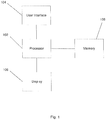
- a system 100 is capable of making modifications to an initial segmentation of an organ or other anatomical structure.
- the system 100 comprises a processor 102 that is capable of processing a segmentation algorithm on a series of volumetric images (e.g., acquired through MRI, CT) to complete an initial segmentation.
- the segmentation algorithm operates either automatically (without user involvement) or semi-automatically to complete the initial segmentation.
- the segmentation algorithm analyzes the image slices and determines the two-dimensional contours of a relevant organ in an image slice without user involvement to complete the initial segmentation.
- semi-automatic operation the user may select a contour or image detail and the algorithm may then complete the initial segmentation based on this selection.
- the initial segmentation is represented by a surface mesh.
- the processor 102 is further capable of interpreting a user input via a user interface 104 of the system 100.
- the system 100 further comprises a display 106 for displaying the surface mesh representation and a memory 108 for storing at least one of the segmentation algorithm, the volumetric images, and the initial surface mesh representation.
- the memory 108 is any known type of computer-readable storage medium. It will be understood by those of skill in the art that the system 100 is a personal computer, a server, or any other processing arrangement.
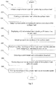
- method 200 comprises initiating a segmentation algorithm, in a step 210, to complete the initial segmentation of an imaged organ, or other anatomic structure, in the series of volumetric images.
- the initial segmentation is represented by a surface mesh that is comprised of triangular polygons formed of vertices and edges.
- Fig. 5 shows an example of a portion of a surface mesh comprising vertices and edges. It will be understood by those of skill in the art that the surface mesh acts as a model or mean organ that may be interactively modified via the user interface 104.
- the processor 102 further creates a volumetric mesh, which is contained within the surface mesh such that vertices and edges of the volumetric mesh are within the vertices and edges of the surface mesh formed by the segmentation algorithm.
- the volumetric mesh includes vertices and edges corresponding to each of the vertices and edges of the surface mesh.
- the processor 102 assigns vertices and edges of the surface mesh with mass points and springs, respectively.
- Each edge of the surface mesh corresponds to a spring while each vertex of the surface mesh corresponds to a mass point.
- the rest length of each spring may be substantially equal to a length of the corresponding edge of the surface mesh.
- each mass point has unit mass and each spring has the same spring constant.
- the mass and spring constant may vary according to prior knowledge about the organ or other anatomic structure that the surface mesh represents. For example, some parts of the organ or structure may be stiffer or more rigid than other parts.
- a 2D reformatted view is displayed on the display 106.
- the 2D reformatted view includes a 2D view of the surface mesh along with the imaged organ. It will be understood by those of skill in the art that the 2D reformatted view is an image from the series of volumetric images that has been reformatted to show the 2D image of both the surface mesh and the imaged organ. It will also be understood by those of skill in the art that the surface mesh is displayed in a position, which corresponds to a position of the imaged organ in the displayed image.
- a point on a surface of the surface mesh is selected.
- the point on the surface of the surface mesh is selected by a user via the user interface 104.
- the user interface 104 includes a mouse, which may be used to point to and click on a point on the surface mesh.
- the user interface 104 may include a touch interface such that the point may be selected by touching a point on the surface of the surface mesh on the display 106. The user selects a point either at random or according to a portion of the surface that the user desires to correct or modify. The selected point will be the point of interaction.
- the selected point may be a feature point on the surface of the surface mesh, which may be identified by the processor 102 or by the user via the user interface 104.
- identifying feature points allows image forces to be added to the surface mesh.
- the processor 102 may identify feature points that show typical characteristics of a point (e.g., corner feature) or contour (e.g., gradient feature) such that placing a mouse pointer in the vicinity of the feature point will result in the pointer "snapping" to the feature point and thereby selecting the feature point.
- the user may select more than one point on the surface of the surface mesh.
- the selected points may also be set (e.g., according to feature points) such that they are changeable by the user.
- a fast marching method is a method of boundary value formulation.
- the fast-marching method assigns a timestamp to each of the vertices on the surface mesh, the timestamp for each vertex being determined by a distance of the vertex from the selected point. Thus, vertices farther away from the selected point are assigned a higher timestamp, while vertices closer to the selected point are assigned a lower timestamp.
- the fast-marching method may also take local orientation of the surface polygons (e.g., triangles) of the surface mesh into consideration.
- a patch of the surface mesh is selected based upon a time threshold, in a step 270.
- the selected patch includes all polygons reached within a certain amount of time.
- the time threshold may be predetermined by the user prior to use.
- the processor 102 may automatically select the patch according to the predetermined threshold. It will also be understood by those of skill in the art, however, that the patch may be selected by the user based upon a threshold determined by the user during use.
- a pull spring is attached to each of the vertices in the patch.
- the pull spring is attached to each vertex such that a first end of the pull spring is attached to the vertex of the surface mesh while a second end of the pull spring is attached to the corresponding vertex of the volumetric mesh.
- Each pull spring will have a rest length of zero.
- a spring constant of each pull spring is weighted according to the corresponding timestamp of the corresponding vertex. For example, pull springs may be down-weighted with respect to closer pull springs. Alternatively, vertices with higher timestamps may be accorded higher masses or may be fixed such that the vertices may not move.
- step 270 is not required. Where a patch is not selected, a pull spring is simply attached from the selected point to a vertex closest to a vertex of the surface mesh closest to the selected point.
- a step 290 the user interactively moves the surface of the surface mesh via an interactive point.
- the interactive point may be the point selected in step 250.
- the interactive point may also be a feature point that shows typical characteristics of a point (e.g., corner feature) or contour (e.g., gradient feature).
- the interactive point is moved to a desired location.
- the desired location may be a corresponding point on a surface of the imaged organ in the 2D reformatted view. It will be understood by those of skill in the art that where the interactive point is close to a feature point, the feature point may be removed to permit movement of the interactive point.
- a numerical solver continuously solves a Netwonian equation for each vertex of the surface mesh such that moving the selected point moves the surface of the surface mesh via the pull springs attached to each of the vertices. Since each pull spring may be assigned a different spring constant based on the timestamp, it will be understood by those of skill in the art that each vertex may move varying distances such that the surface of the surface mesh moves in an intuitive manner.
- the distance moved by each of the vertices is determined based upon a distance from the selected point (i.e., the point of interaction).
- the processor 102 uses any standard solver such as, for example, Euler Runge-Kutta, which is preloaded into the memory 108 of the system 100, or is otherwise made available for use. It will be understood by those of skill in the art that the steps 250 - 290 may be repeated until the surface mesh has been modified as desired.
- the point of interaction of step 290 is selected based on the form of the surface mesh. For example, where the surface mesh is jagged, a jagged corner of the surface mesh is selected and a distance map of ends of the corner is determined and subtracted to reduce the jagged edge.
- the interactive point of the step 290 is a steerable ball or point that is moved by the user via the user interface 104.
- the steerable ball may be either two dimensional or three dimensional, creating an attraction/repulsion field such that any of the vertices that fall within the sphere of the streerable ball is attracted or repelled to move the vertex in line with a motion of the steerable ball.
- Fig. 3 shows a method 300, which is substantially similar to the method 200, described above.
- the method 300 differs in user selection of interaction points.
- Steps 310 - 340 are substantially similar to steps 210 - 240 of the method 200.
- the method 300 comprises initiating a segmentation algorithm, in the step 310, which completes an initial segmentation, as similarly described instep 210 of method 200.
- This initial segmentation produces a surface mesh comprised of vertices and edges.
- a volumetric mesh is formed, within the surface mesh of the initial segmentation.
- the processor 102 assigns each of the vertices of the surface mesh a mass point and each of the edges a spring.
- the display 106 displays a 2D reformatted view of a 2D view of the surface mesh along with the 2D view of the imaged organ such that the user may determine modifications to be made on the surface mesh.
- a step 350 the user draws a 2D contour of the imaged organ.
- the 2D contour may be drawn using a drawing tool such as, for example, Livewire, which allows the user to draw a contour based upon points selected on a surface of the imaged organ. Livewire is used by the user to draw connecting lines between each of the points to draw in the surface of the imaged organ.
- a drawing tool such as, for example, Livewire
- Livewire is used by the user to draw connecting lines between each of the points to draw in the surface of the imaged organ.
- the points of the 2D contour are then connected to points on a surface of the surface mesh, in a step 355.
- the user selects a point on the surface of the surface mesh to which the 2D contour should be connected.
- the processor 102 performs a fast-marching method, similar to the step 260, assigning timestamps to each of the vertices of the surface mesh.
- Steps 360 - 390 are substantially similar to steps 260 - 290, as described above in regard to method 200.
- a patch is selected based upon a time threshold and in the step 380, pull springs are attached to each of the vertices in the selected patch. It will be understood by those of skill in the art that the step 370 is not required. Where a patch is not selected, a pull spring may be added from a point of the 2D contour to a vertex of the surface mesh closest to the point of the 2D contour, in the step 380. In the step 390, the processor 102 calculates the Newtonian equation for each of the vertices with the pull spring attached thereto, to determine a distance by which the vertex will move when the selected point on the surface of the surface mesh is connected to the points on the 2D contour. It will be understood by those of skill in the art that the steps 360 - 390 may be repeated for each of the points on the surface of the surface mesh that are selected by the user to be connected to points on the 2D contour.
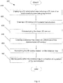
- a method 400 comprises displaying a 2D reformatted view of an imaged organ or other anatomic structure on the display 106, in a step 410.
- the user draws a 2D contour of the imaged organ.
- the 2D contour is for example drawn using a drawing tool such as, for example, Livewire, which allows the user to draw a contour based upon points selected on a surface of the imaged organ. Livewire is used by the user to draw connecting lines between each of the points to draw in the surface of the imaged organ.
- a drawing tool such as, for example, Livewire, which allows the user to draw a contour based upon points selected on a surface of the imaged organ. Livewire is used by the user to draw connecting lines between each of the points to draw in the surface of the imaged organ.
- Livewire is used by the user to draw connecting lines between each of the points to draw in the surface of the imaged organ.
- a Deriche filter is used for 3D edge and feature detection such that structures in the image are delineated and a 2D contour is determined by the processor 102.
- the Deriche filter recognizes feature values, which are then interpolated during a feature search such that outlines of structures are made clearly visible.
- the processor 102 downsamples the drawn 2D contour by, for example, reducing a resolution of the 2D contour such that edges are blurred. It will be understood by those of skill in the art that downsampling of the 2D contour reduces any sharp edges of the 2D contour while increasing a thickness of the drawn 2D contour.
- the processor 102 then creates a distance map of the thickness of the downsampled 2D contour, in a step 440, measuring a distance between outer and inner edges of the downsampled 2D contour.
- the distance map is used to normalize the downsampled 2D contour using, for example, a Gaussian distribution, such that points of the 2D contour within the distance map are pulled in the direction of a gradient of normalization in a step 460. Moving the points within the distance map creates a smooth surface of the 2D contour, closer to a surface of the imaged structure. It will be understood by those of skill in the art that the steps 420 - 460 may be repeated as necessary, until the 2D contour, is sufficiently close to the surface of the imaged organ.
- exemplary embodiments or portions of the exemplary embodiments may be implemented as a set of instructions stored on a computer readable storage medium, the set of instructions being executable by a processor.
Landscapes
- Engineering & Computer Science (AREA)
- Software Systems (AREA)
- Computer Vision & Pattern Recognition (AREA)
- Physics & Mathematics (AREA)
- General Physics & Mathematics (AREA)
- Theoretical Computer Science (AREA)
- Apparatus For Radiation Diagnosis (AREA)
- Image Processing (AREA)
- Magnetic Resonance Imaging Apparatus (AREA)
- Image Analysis (AREA)
Claims (9)
- Verfahren zur Segmentierung einer anatomischen Struktur, wonach:ein Segmentierungsalgorithmus initiiert wird (210, 310), der ein Oberflächen-Mesh der anatomischen Struktur aus einem volumetrischen Bild erzeugt, wobei das aus einer Vielzahl von Polygonen gebildete Oberflächen-Mesh Eckpunkte und Ränder umfasst;jedem der Ränder eine Feder und jedem der Eckpunkte des Oberflächen-Mesh ein Massepunkt zugewiesen wird (230, 330);eine reformatierte 2D-Ansicht mit einer 2D-Ansicht des Oberflächen-Mesh und der anatomischen Struktur dargestellt wird (240, 340);von einem Benutzer ein Punkt auf dem Oberflächen-Mesh ausgewählt wird (250, 355),Zugfedern zu Eckpunkten des Oberflächen-Mesh hinzugefügt werden (280, 380), indem entwedera) ein volumetrisches Mesh unmittelbar innerhalb des Oberflächen-Mesh gebildet wird (220, 320), wobei das volumetrische Mesh Eckpunkte und Ränder entsprechend den Eckpunkten und Rändern des Oberflächen-Mesh umfasst; eine Zugfeder zwischen einem Eckpunkt des Oberflächen-Mesh und einem entsprechenden Eckpunkt des volumetrischen Mesh, basierend auf dem Abstand des Eckpunkts von dem ausgewählten Punkt, hinzugefügt wird;
oderb) eine 2D-Kontur der anatomischen Struktur von einem Benutzer gezogen wird (350), wobei die 2D-Kontur eine Vielzahl von miteinander verbundenen Punkten umfasst; eine Zugfeder von einem Punkt der 2D-Kontur zu einem Eckpunkt des Oberflächen-Mesh, der dem Punkt der 2D-Kontur am nächsten ist, hinzugefügt wird;ein Abschnitt des Oberflächen-Mesh bewegt wird (290, 390), indem ein Benutzer den ausgewählten Punkt in eine gewünschte Position bewegt, wobei der Abstand, um den sich jeder Eckpunkt innerhalb des Abschnitts verschiebt, durch einen Abstand des Eckpunkts von dem ausgewählten Punkt ermittelt wird. - Verfahren nach Anspruch 1, wonach bei Hinzufügen (280, 380) von Zugfedern zu Eckpunkten des Oberflächen-Mesh durch Schritt a) weiterhin:ein Fast-Marching-Verfahren von dem ausgewählten Punkt aus durchgeführt wird (260, 360), wobei das Fast-Marching-Verfahren jedem der Eckpunkte des Oberflächen-Mesh einen Zeitstempel zuweist, wobei der Zeitstempel auf einem Abstand von dem ausgewählten Punkt basiert.
- Verfahren nach Anspruch 2, wonach bei Hinzufügen (280, 380) von Zugfedern zu Eckpunkten des Oberflächen-Mesh durch Schritt a) weiterhin:ein Polygon-Patch, basierend auf einem Schwellenwert von Zeitstempelwerten, ausgewählt wird (270, 370).
- Verfahren nach Anspruch 3, wonach bei Hinzufügen (280, 380) von Zugfedern zu Eckpunkten des Oberflächen-Mesh durch Schritt a) weiterhin:eine Zugfeder zu jedem der Eckpunkte des Patch hinzugefügt wird und ein erstes Ende der Zugfeder an dem Eckpunkt des Oberflächen-Mesh angebracht wird und ein zweites Ende an einem entsprechenden Eckpunkt des volumetrischen Mesh angebracht wird.
- Verfahren nach Anspruch 4, wobei eine Federkonstante der Zugfeder, basierend auf dem entsprechenden Zeitstempelwert, gewichtet wird.
- Verfahren nach Anspruch 2, wobei der Massepunkt jedes der Eckpunkte, basierend auf dem entsprechenden Zeitstempelwert oder einem Bildgradienten, gewichtet wird.
- System zur Segmentierung einer anatomischen Struktur, umfassend:einen Prozessor (102), der einen Segmentierungsalgorithmus initiiert, der ein Oberflächen-Mesh der anatomischen Struktur aus einem volumetrischen Bild erzeugt, wobei das aus einer Vielzahl von Polygonen gebildete Oberflächen-Mesh Eckpunkte und Ränder umfasst, weiterhin jedem der Ränder eine Feder und jedem der Eckpunkte des Oberflächen-Mesh einen Massepunkt zuweist;ein Display (106) zur Darstellung einer reformatierten 2D-Ansicht mit einer 2D-Ansicht des Oberflächen-Mesh und der anatomischen Struktur; sowieeine Benutzeroberfläche (104), die so eingerichtet ist, dass sie es einem Benutzer ermöglicht, einen Punkt auf dem Oberflächen-Mesh auszuwählen und Zugfedern zu Eckpunkten des Oberflächen-Mesh hinzuzufügen, indem entwedera) durch den Prozessor (102) ein volumetrisches Mesh unmittelbar innerhalb des Oberflächen-Mesh gebildet wird (220, 320), wobei das volumetrische Mesh Eckpunkte und Ränder entsprechend den Eckpunkten und Rändern des Oberflächen-Mesh umfasst; und eine Zugfeder zwischen einem Eckpunkt des Oberflächen-Mesh und einem entsprechenden Eckpunkt des volumetrischen Mesh, basierend auf dem Abstand des Eckpunkts von dem ausgewählten Punkt, hinzugefügt wird;
oderb) es dem Benutzer ermöglicht wird, eine 2D-Kontur der anatomischen Struktur zu ziehen (350), wobei die 2D-Kontur eine Vielzahl von miteinander verbundenen Punkten umfasst, und eine Zugfeder von einem Punkt der 2D-Kontur zu einem Eckpunkt des Oberflächen-Mesh, der dem Punkt der 2D-Kontur am nächsten ist, hinzuzufügen;wobei der Prozessor (102) weiterhin so eingerichtet ist, dass er einen Abschnitt des Oberflächen-Mesh bewegt, indem ein Benutzer den ausgewählten Punkt mittels der Benutzeroberfläche (104) in eine gewünschte Position bewegt, wobei der Abstand, um den sich jeder Eckpunkt innerhalb des Abschnitts verschiebt, durch einen Abstand des Eckpunkts von dem ausgewählten Punkt ermittelt wird. - System nach Anspruch 7, wobei, wenn mit Hilfe der Benutzeroberfläche Zugfedern zu Eckpunkten des Oberflächen-Mesh, basierend auf dem ausgewählten Punkt, durch Schritt a) hinzugefügt werden, der Prozessor (102) ein Fast-Marching-Verfahren von dem ausgewählten Punkt aus durchführt, wobei das Fast-Marching-Verfahren jedem der Eckpunkte des Oberflächen-Mesh einen Zeitstempel zuweist, wobei der Zeitstempel auf einem Abstand von dem ausgewählten Punkt basiert.
- System nach Anspruch 8, wobei, wenn mit Hilfe der Benutzeroberfläche Zugfedern zu Eckpunkten des Oberflächen-Mesh, basierend auf dem ausgewählten Punkt, durch Schritt a) hinzugefügt werden, die Benutzeroberfläche (104) so eingerichtet ist, dass sie es einem Benutzer ermöglicht, ein Polygon-Patch, basierend auf einem Schwellenwert von Zeitstempelwerten, auszuwählen, und der Prozessor (102) eine Zugfeder zu jedem der Eckpunkte innerhalb des Patch hinzufügt.
Priority Applications (1)
| Application Number | Priority Date | Filing Date | Title |
|---|---|---|---|
| PL10715355T PL2415018T3 (pl) | 2009-04-03 | 2010-03-02 | UKŁAD I SPOSÓB INTERAKTYWNEJ SEGMENTACJl SIATKI W CZASIE RZECZYWISTYM |
Applications Claiming Priority (2)
| Application Number | Priority Date | Filing Date | Title |
|---|---|---|---|
| US16626309P | 2009-04-03 | 2009-04-03 | |
| PCT/IB2010/050897 WO2010113051A1 (en) | 2009-04-03 | 2010-03-02 | System and method for interactive live-mesh segmentation |
Publications (2)
| Publication Number | Publication Date |
|---|---|
| EP2415018A1 EP2415018A1 (de) | 2012-02-08 |
| EP2415018B1 true EP2415018B1 (de) | 2017-10-25 |
Family
ID=42225065
Family Applications (1)
| Application Number | Title | Priority Date | Filing Date |
|---|---|---|---|
| EP10715355.3A Not-in-force EP2415018B1 (de) | 2009-04-03 | 2010-03-02 | System und verfahren für interaktive live-mesh-segmentierung |
Country Status (7)
| Country | Link |
|---|---|
| US (1) | US20120026168A1 (de) |
| EP (1) | EP2415018B1 (de) |
| JP (1) | JP5451871B2 (de) |
| CN (1) | CN102378990B (de) |
| PL (1) | PL2415018T3 (de) |
| RU (1) | RU2523915C2 (de) |
| WO (1) | WO2010113051A1 (de) |
Families Citing this family (7)
| Publication number | Priority date | Publication date | Assignee | Title |
|---|---|---|---|---|
| US8907944B2 (en) | 2011-06-28 | 2014-12-09 | General Electric Company | Method and system for navigating, segmenting, and extracting a three-dimensional image |
| US8477153B2 (en) | 2011-08-24 | 2013-07-02 | General Electric Company | Method and system for navigating, segmenting, and extracting a three-dimensional image |
| CN102760236B (zh) * | 2012-03-20 | 2014-10-01 | 苏州迪凯尔医疗科技有限公司 | 基于组合稀疏模型的先验形状建模方法 |
| US9189860B2 (en) | 2013-04-22 | 2015-11-17 | General Electric Company | Real-time, interactive image analysis |
| WO2016097920A1 (en) * | 2014-12-18 | 2016-06-23 | Koninklijke Philips N.V. | Medical image editing |
| WO2017001476A1 (en) * | 2015-06-29 | 2017-01-05 | Koninklijke Philips N.V. | Interactive mesh editing |
| CN110139609B (zh) * | 2016-12-12 | 2022-06-03 | 佳能株式会社 | 图像处理装置、图像处理方法和程序 |
Family Cites Families (13)
| Publication number | Priority date | Publication date | Assignee | Title |
|---|---|---|---|---|
| US6256038B1 (en) * | 1998-12-10 | 2001-07-03 | The Board Of Trustees Of The Leland Stanford Junior University | Parameterized surface fitting technique having independent control of fitting and parameterization |
| US6469701B1 (en) * | 1999-07-19 | 2002-10-22 | Stefan Gumhold | Method for compressing graphical information |
| US8988419B2 (en) * | 2000-11-27 | 2015-03-24 | Ding Huang | Parameterization of deformation and simulation of interaction |
| US6631202B2 (en) * | 2000-12-08 | 2003-10-07 | Landmark Graphics Corporation | Method for aligning a lattice of points in response to features in a digital image |
| WO2005038711A1 (en) * | 2003-10-17 | 2005-04-28 | Koninklijke Philips Electronics, N.V. | Manual tools for model based image segmentation |
| US7889209B2 (en) * | 2003-12-10 | 2011-02-15 | Sensable Technologies, Inc. | Apparatus and methods for wrapping texture onto the surface of a virtual object |
| JP2007518484A (ja) * | 2004-01-19 | 2007-07-12 | コーニンクレッカ フィリップス エレクトロニクス エヌ ヴィ | 変形可能な表面のセグメント化のリアルタイムなユーザ対話処理 |
| US7182534B2 (en) * | 2004-09-22 | 2007-02-27 | Dell Products L.P. | System and method for integrated dye sublimation photo printer paper tray |
| US7286127B2 (en) * | 2005-06-22 | 2007-10-23 | Microsoft Corporation | Large mesh deformation using the volumetric graph Laplacian |
| US20090115796A1 (en) * | 2005-09-23 | 2009-05-07 | Koninklijke Philips Electronics, N.V. | Priori information encoding for manual adaptation of geometric models |
| US8065028B1 (en) * | 2007-04-24 | 2011-11-22 | Nasser Saebi | Method of constructing a composite structure |
| EP2006803A1 (de) * | 2007-06-19 | 2008-12-24 | Agfa HealthCare NV | Verfahren zur Segmentierung anatomischer Entitäten in medizinischen 3D-Bildern |
| US8005659B2 (en) * | 2007-07-06 | 2011-08-23 | Immersion Medical, Inc. | Simulation of coupled objects |
-
2010
- 2010-03-02 EP EP10715355.3A patent/EP2415018B1/de not_active Not-in-force
- 2010-03-02 US US13/262,749 patent/US20120026168A1/en not_active Abandoned
- 2010-03-02 WO PCT/IB2010/050897 patent/WO2010113051A1/en active Application Filing
- 2010-03-02 PL PL10715355T patent/PL2415018T3/pl unknown
- 2010-03-02 RU RU2011144580/08A patent/RU2523915C2/ru not_active IP Right Cessation
- 2010-03-02 JP JP2012502835A patent/JP5451871B2/ja not_active Expired - Fee Related
- 2010-03-02 CN CN201080015315.3A patent/CN102378990B/zh not_active Expired - Fee Related
Non-Patent Citations (1)
| Title |
|---|
| URBAN ET AL: "Physical simulation of deformable objects with applications in radiotherapy", THESIS,, 1 January 2007 (2007-01-01), pages 1 - 81, XP009191799 * |
Also Published As
| Publication number | Publication date |
|---|---|
| US20120026168A1 (en) | 2012-02-02 |
| JP5451871B2 (ja) | 2014-03-26 |
| CN102378990A (zh) | 2012-03-14 |
| RU2523915C2 (ru) | 2014-07-27 |
| JP2012522558A (ja) | 2012-09-27 |
| EP2415018A1 (de) | 2012-02-08 |
| CN102378990B (zh) | 2015-05-27 |
| WO2010113051A1 (en) | 2010-10-07 |
| PL2415018T3 (pl) | 2018-03-30 |
| RU2011144580A (ru) | 2013-05-10 |
Similar Documents
| Publication | Publication Date | Title |
|---|---|---|
| EP2415018B1 (de) | System und verfahren für interaktive live-mesh-segmentierung | |
| US20240062488A1 (en) | Object centric scanning | |
| US20120027277A1 (en) | Interactive iterative closest point algorithm for organ segmentation | |
| CN110599528A (zh) | 一种基于神经网络的无监督三维医学图像配准方法及系统 | |
| US20090278846A1 (en) | System and method for geometric modeling of tubular structures | |
| CN108717700B (zh) | 一种检测结节长短径长度的方法及装置 | |
| CN109583509B (zh) | 数据生成方法、装置及电子设备 | |
| JP6385318B2 (ja) | 3d医用画像中の対象物をセグメンテーションするための3d対象物の変換 | |
| EP3971840A1 (de) | Verfahren zur erzeugung eines dreidimensionalen modells; verfahren zur erzeugung eines neuronalen netzes und vorrichtungen | |
| CN110832542B (zh) | 识别处理设备、识别处理方法和程序 | |
| EP1685534B1 (de) | Dreidimensionale segmentierung durch verwendung deformierbarer oberflächen | |
| JP2007518484A (ja) | 変形可能な表面のセグメント化のリアルタイムなユーザ対話処理 | |
| US20160335758A1 (en) | Methods and systems for characterizing concept drawings and estimating three-dimensional information therefrom | |
| WO2021263035A1 (en) | Object recognition neural network for amodal center prediction | |
| CN116310066A (zh) | 一种单图像三维人体形态估计方法及应用 | |
| CN116168384A (zh) | 点云目标检测方法、装置、电子设备及存储介质 | |
| JP2020181283A (ja) | 情報処理装置、情報処理方法、寸法データ算出装置、及び製品製造装置 | |
| CN108090953B (zh) | 感兴趣区域重建方法、系统以及计算机可读存储介质 | |
| EP2266457A1 (de) | Intermediäres bilderzeugungsverfahren, vorrichtung und programm | |
| JP4720478B2 (ja) | モデリング装置、領域抽出装置およびプログラム | |
| JP4736755B2 (ja) | モデリング装置、領域抽出装置、モデリング方法及びプログラム | |
| CN115409856A (zh) | 一种肺部医学图像处理方法、装置、设备及存储介质 | |
| Blezek et al. | Center line algorithm for virtual endoscopy based on chamfer distance transform and Dijkstra's single-source shortest-path algorithm | |
| CN113487575B (zh) | 用于训练医学影像检测模型的方法及装置、设备、可读存储介质 | |
| CN117152174A (zh) | 用于生成肋骨图像的方法、装置及计算机可读存储介质 |
Legal Events
| Date | Code | Title | Description |
|---|---|---|---|
| PUAI | Public reference made under article 153(3) epc to a published international application that has entered the european phase |
Free format text: ORIGINAL CODE: 0009012 |
|
| 17P | Request for examination filed |
Effective date: 20111103 |
|
| AK | Designated contracting states |
Kind code of ref document: A1 Designated state(s): AT BE BG CH CY CZ DE DK EE ES FI FR GB GR HR HU IE IS IT LI LT LU LV MC MK MT NL NO PL PT RO SE SI SK SM TR |
|
| DAX | Request for extension of the european patent (deleted) | ||
| 17Q | First examination report despatched |
Effective date: 20120730 |
|
| RAP1 | Party data changed (applicant data changed or rights of an application transferred) |
Owner name: PHILIPS INTELLECTUAL PROPERTY & STANDARDS GMBH Owner name: KONINKLIJKE PHILIPS N.V. |
|
| STAA | Information on the status of an ep patent application or granted ep patent |
Free format text: STATUS: EXAMINATION IS IN PROGRESS |
|
| GRAP | Despatch of communication of intention to grant a patent |
Free format text: ORIGINAL CODE: EPIDOSNIGR1 |
|
| STAA | Information on the status of an ep patent application or granted ep patent |
Free format text: STATUS: GRANT OF PATENT IS INTENDED |
|
| INTG | Intention to grant announced |
Effective date: 20170519 |
|
| RIN1 | Information on inventor provided before grant (corrected) |
Inventor name: SCHULZ, HEINRICH Inventor name: VIK, TORBJOERN |
|
| GRAS | Grant fee paid |
Free format text: ORIGINAL CODE: EPIDOSNIGR3 |
|
| GRAA | (expected) grant |
Free format text: ORIGINAL CODE: 0009210 |
|
| STAA | Information on the status of an ep patent application or granted ep patent |
Free format text: STATUS: THE PATENT HAS BEEN GRANTED |
|
| AK | Designated contracting states |
Kind code of ref document: B1 Designated state(s): AT BE BG CH CY CZ DE DK EE ES FI FR GB GR HR HU IE IS IT LI LT LU LV MC MK MT NL NO PL PT RO SE SI SK SM TR |
|
| REG | Reference to a national code |
Ref country code: GB Ref legal event code: FG4D |
|
| REG | Reference to a national code |
Ref country code: CH Ref legal event code: EP |
|
| REG | Reference to a national code |
Ref country code: AT Ref legal event code: REF Ref document number: 940566 Country of ref document: AT Kind code of ref document: T Effective date: 20171115 |
|
| REG | Reference to a national code |
Ref country code: IE Ref legal event code: FG4D |
|
| REG | Reference to a national code |
Ref country code: DE Ref legal event code: R096 Ref document number: 602010046189 Country of ref document: DE |
|
| REG | Reference to a national code |
Ref country code: NL Ref legal event code: MP Effective date: 20171025 |
|
| REG | Reference to a national code |
Ref country code: LT Ref legal event code: MG4D |
|
| REG | Reference to a national code |
Ref country code: AT Ref legal event code: MK05 Ref document number: 940566 Country of ref document: AT Kind code of ref document: T Effective date: 20171025 |
|
| REG | Reference to a national code |
Ref country code: DE Ref legal event code: R081 Ref document number: 602010046189 Country of ref document: DE Owner name: PHILIPS GMBH, DE Free format text: FORMER OWNER: PHILIPS INTELLECTUAL PROPERTY & STANDARDS GMBH, 20099 HAMBURG, DE |
|
| PG25 | Lapsed in a contracting state [announced via postgrant information from national office to epo] |
Ref country code: NL Free format text: LAPSE BECAUSE OF FAILURE TO SUBMIT A TRANSLATION OF THE DESCRIPTION OR TO PAY THE FEE WITHIN THE PRESCRIBED TIME-LIMIT Effective date: 20171025 |
|
| PG25 | Lapsed in a contracting state [announced via postgrant information from national office to epo] |
Ref country code: ES Free format text: LAPSE BECAUSE OF FAILURE TO SUBMIT A TRANSLATION OF THE DESCRIPTION OR TO PAY THE FEE WITHIN THE PRESCRIBED TIME-LIMIT Effective date: 20171025 Ref country code: LT Free format text: LAPSE BECAUSE OF FAILURE TO SUBMIT A TRANSLATION OF THE DESCRIPTION OR TO PAY THE FEE WITHIN THE PRESCRIBED TIME-LIMIT Effective date: 20171025 Ref country code: NO Free format text: LAPSE BECAUSE OF FAILURE TO SUBMIT A TRANSLATION OF THE DESCRIPTION OR TO PAY THE FEE WITHIN THE PRESCRIBED TIME-LIMIT Effective date: 20180125 Ref country code: SE Free format text: LAPSE BECAUSE OF FAILURE TO SUBMIT A TRANSLATION OF THE DESCRIPTION OR TO PAY THE FEE WITHIN THE PRESCRIBED TIME-LIMIT Effective date: 20171025 Ref country code: FI Free format text: LAPSE BECAUSE OF FAILURE TO SUBMIT A TRANSLATION OF THE DESCRIPTION OR TO PAY THE FEE WITHIN THE PRESCRIBED TIME-LIMIT Effective date: 20171025 |
|
| PG25 | Lapsed in a contracting state [announced via postgrant information from national office to epo] |
Ref country code: LV Free format text: LAPSE BECAUSE OF FAILURE TO SUBMIT A TRANSLATION OF THE DESCRIPTION OR TO PAY THE FEE WITHIN THE PRESCRIBED TIME-LIMIT Effective date: 20171025 Ref country code: IS Free format text: LAPSE BECAUSE OF FAILURE TO SUBMIT A TRANSLATION OF THE DESCRIPTION OR TO PAY THE FEE WITHIN THE PRESCRIBED TIME-LIMIT Effective date: 20180225 Ref country code: BG Free format text: LAPSE BECAUSE OF FAILURE TO SUBMIT A TRANSLATION OF THE DESCRIPTION OR TO PAY THE FEE WITHIN THE PRESCRIBED TIME-LIMIT Effective date: 20180125 Ref country code: HR Free format text: LAPSE BECAUSE OF FAILURE TO SUBMIT A TRANSLATION OF THE DESCRIPTION OR TO PAY THE FEE WITHIN THE PRESCRIBED TIME-LIMIT Effective date: 20171025 Ref country code: AT Free format text: LAPSE BECAUSE OF FAILURE TO SUBMIT A TRANSLATION OF THE DESCRIPTION OR TO PAY THE FEE WITHIN THE PRESCRIBED TIME-LIMIT Effective date: 20171025 Ref country code: GR Free format text: LAPSE BECAUSE OF FAILURE TO SUBMIT A TRANSLATION OF THE DESCRIPTION OR TO PAY THE FEE WITHIN THE PRESCRIBED TIME-LIMIT Effective date: 20180126 |
|
| REG | Reference to a national code |
Ref country code: DE Ref legal event code: R097 Ref document number: 602010046189 Country of ref document: DE |
|
| PG25 | Lapsed in a contracting state [announced via postgrant information from national office to epo] |
Ref country code: CZ Free format text: LAPSE BECAUSE OF FAILURE TO SUBMIT A TRANSLATION OF THE DESCRIPTION OR TO PAY THE FEE WITHIN THE PRESCRIBED TIME-LIMIT Effective date: 20171025 Ref country code: CY Free format text: LAPSE BECAUSE OF FAILURE TO SUBMIT A TRANSLATION OF THE DESCRIPTION OR TO PAY THE FEE WITHIN THE PRESCRIBED TIME-LIMIT Effective date: 20171025 Ref country code: EE Free format text: LAPSE BECAUSE OF FAILURE TO SUBMIT A TRANSLATION OF THE DESCRIPTION OR TO PAY THE FEE WITHIN THE PRESCRIBED TIME-LIMIT Effective date: 20171025 Ref country code: DK Free format text: LAPSE BECAUSE OF FAILURE TO SUBMIT A TRANSLATION OF THE DESCRIPTION OR TO PAY THE FEE WITHIN THE PRESCRIBED TIME-LIMIT Effective date: 20171025 Ref country code: SK Free format text: LAPSE BECAUSE OF FAILURE TO SUBMIT A TRANSLATION OF THE DESCRIPTION OR TO PAY THE FEE WITHIN THE PRESCRIBED TIME-LIMIT Effective date: 20171025 |
|
| PG25 | Lapsed in a contracting state [announced via postgrant information from national office to epo] |
Ref country code: IT Free format text: LAPSE BECAUSE OF FAILURE TO SUBMIT A TRANSLATION OF THE DESCRIPTION OR TO PAY THE FEE WITHIN THE PRESCRIBED TIME-LIMIT Effective date: 20171025 Ref country code: RO Free format text: LAPSE BECAUSE OF FAILURE TO SUBMIT A TRANSLATION OF THE DESCRIPTION OR TO PAY THE FEE WITHIN THE PRESCRIBED TIME-LIMIT Effective date: 20171025 Ref country code: SM Free format text: LAPSE BECAUSE OF FAILURE TO SUBMIT A TRANSLATION OF THE DESCRIPTION OR TO PAY THE FEE WITHIN THE PRESCRIBED TIME-LIMIT Effective date: 20171025 |
|
| PLBE | No opposition filed within time limit |
Free format text: ORIGINAL CODE: 0009261 |
|
| STAA | Information on the status of an ep patent application or granted ep patent |
Free format text: STATUS: NO OPPOSITION FILED WITHIN TIME LIMIT |
|
| REG | Reference to a national code |
Ref country code: DE Ref legal event code: R119 Ref document number: 602010046189 Country of ref document: DE |
|
| 26N | No opposition filed |
Effective date: 20180726 |
|
| REG | Reference to a national code |
Ref country code: CH Ref legal event code: PL |
|
| GBPC | Gb: european patent ceased through non-payment of renewal fee |
Effective date: 20180302 |
|
| PG25 | Lapsed in a contracting state [announced via postgrant information from national office to epo] |
Ref country code: MC Free format text: LAPSE BECAUSE OF FAILURE TO SUBMIT A TRANSLATION OF THE DESCRIPTION OR TO PAY THE FEE WITHIN THE PRESCRIBED TIME-LIMIT Effective date: 20171025 Ref country code: SI Free format text: LAPSE BECAUSE OF FAILURE TO SUBMIT A TRANSLATION OF THE DESCRIPTION OR TO PAY THE FEE WITHIN THE PRESCRIBED TIME-LIMIT Effective date: 20171025 |
|
| REG | Reference to a national code |
Ref country code: BE Ref legal event code: MM Effective date: 20180331 |
|
| REG | Reference to a national code |
Ref country code: IE Ref legal event code: MM4A |
|
| PG25 | Lapsed in a contracting state [announced via postgrant information from national office to epo] |
Ref country code: LU Free format text: LAPSE BECAUSE OF NON-PAYMENT OF DUE FEES Effective date: 20180302 |
|
| PG25 | Lapsed in a contracting state [announced via postgrant information from national office to epo] |
Ref country code: IE Free format text: LAPSE BECAUSE OF NON-PAYMENT OF DUE FEES Effective date: 20180302 Ref country code: DE Free format text: LAPSE BECAUSE OF NON-PAYMENT OF DUE FEES Effective date: 20181002 |
|
| PG25 | Lapsed in a contracting state [announced via postgrant information from national office to epo] |
Ref country code: GB Free format text: LAPSE BECAUSE OF NON-PAYMENT OF DUE FEES Effective date: 20180302 Ref country code: CH Free format text: LAPSE BECAUSE OF NON-PAYMENT OF DUE FEES Effective date: 20180331 Ref country code: LI Free format text: LAPSE BECAUSE OF NON-PAYMENT OF DUE FEES Effective date: 20180331 Ref country code: BE Free format text: LAPSE BECAUSE OF NON-PAYMENT OF DUE FEES Effective date: 20180331 |
|
| PG25 | Lapsed in a contracting state [announced via postgrant information from national office to epo] |
Ref country code: FR Free format text: LAPSE BECAUSE OF NON-PAYMENT OF DUE FEES Effective date: 20180331 |
|
| PG25 | Lapsed in a contracting state [announced via postgrant information from national office to epo] |
Ref country code: PL Free format text: LAPSE BECAUSE OF NON-PAYMENT OF DUE FEES Effective date: 20180302 |
|
| PG25 | Lapsed in a contracting state [announced via postgrant information from national office to epo] |
Ref country code: MT Free format text: LAPSE BECAUSE OF NON-PAYMENT OF DUE FEES Effective date: 20180302 |
|
| PG25 | Lapsed in a contracting state [announced via postgrant information from national office to epo] |
Ref country code: PT Free format text: LAPSE BECAUSE OF FAILURE TO SUBMIT A TRANSLATION OF THE DESCRIPTION OR TO PAY THE FEE WITHIN THE PRESCRIBED TIME-LIMIT Effective date: 20171025 Ref country code: HU Free format text: LAPSE BECAUSE OF FAILURE TO SUBMIT A TRANSLATION OF THE DESCRIPTION OR TO PAY THE FEE WITHIN THE PRESCRIBED TIME-LIMIT; INVALID AB INITIO Effective date: 20100302 |
|
| PG25 | Lapsed in a contracting state [announced via postgrant information from national office to epo] |
Ref country code: MK Free format text: LAPSE BECAUSE OF NON-PAYMENT OF DUE FEES Effective date: 20171025 |
|
| PG25 | Lapsed in a contracting state [announced via postgrant information from national office to epo] |
Ref country code: TR Free format text: LAPSE BECAUSE OF NON-PAYMENT OF DUE FEES Effective date: 20180302 |