EP2413813B1 - Abgabesystem für eine magnetische anastomose-vorrichtung - Google Patents
Abgabesystem für eine magnetische anastomose-vorrichtung Download PDFInfo
- Publication number
- EP2413813B1 EP2413813B1 EP10712287.1A EP10712287A EP2413813B1 EP 2413813 B1 EP2413813 B1 EP 2413813B1 EP 10712287 A EP10712287 A EP 10712287A EP 2413813 B1 EP2413813 B1 EP 2413813B1
- Authority
- EP
- European Patent Office
- Prior art keywords
- magnet
- catheter
- wire guide
- lumen
- delivery system
- Prior art date
- Legal status (The legal status is an assumption and is not a legal conclusion. Google has not performed a legal analysis and makes no representation as to the accuracy of the status listed.)
- Active
Links
- 230000003872 anastomosis Effects 0.000 title claims description 13
- 238000004891 communication Methods 0.000 claims description 4
- 230000009278 visceral effect Effects 0.000 claims description 2
- 238000000034 method Methods 0.000 description 25
- 230000000712 assembly Effects 0.000 description 11
- 238000000429 assembly Methods 0.000 description 11
- 210000001630 jejunum Anatomy 0.000 description 11
- 210000001835 viscera Anatomy 0.000 description 10
- 210000002784 stomach Anatomy 0.000 description 9
- 238000002594 fluoroscopy Methods 0.000 description 5
- 239000003550 marker Substances 0.000 description 5
- 230000017074 necrotic cell death Effects 0.000 description 5
- 210000000056 organ Anatomy 0.000 description 5
- 230000000302 ischemic effect Effects 0.000 description 4
- 239000000463 material Substances 0.000 description 4
- 241001465754 Metazoa Species 0.000 description 3
- 238000012986 modification Methods 0.000 description 3
- 230000004048 modification Effects 0.000 description 3
- 210000000813 small intestine Anatomy 0.000 description 3
- 0 C=*1CCCC1 Chemical compound C=*1CCCC1 0.000 description 2
- 206010029957 Obstruction gastric Diseases 0.000 description 2
- 201000000660 Pyloric Stenosis Diseases 0.000 description 2
- 210000001124 body fluid Anatomy 0.000 description 2
- 210000001953 common bile duct Anatomy 0.000 description 2
- 230000010339 dilation Effects 0.000 description 2
- 230000009977 dual effect Effects 0.000 description 2
- 210000001198 duodenum Anatomy 0.000 description 2
- 230000000694 effects Effects 0.000 description 2
- 229920001971 elastomer Polymers 0.000 description 2
- 239000004744 fabric Substances 0.000 description 2
- 210000000232 gallbladder Anatomy 0.000 description 2
- 230000002496 gastric effect Effects 0.000 description 2
- 208000008386 gastric outlet obstruction Diseases 0.000 description 2
- 229920000642 polymer Polymers 0.000 description 2
- 210000001187 pylorus Anatomy 0.000 description 2
- 206010028980 Neoplasm Diseases 0.000 description 1
- 208000031481 Pathologic Constriction Diseases 0.000 description 1
- 229920006362 Teflon® Polymers 0.000 description 1
- 208000025865 Ulcer Diseases 0.000 description 1
- 210000000683 abdominal cavity Anatomy 0.000 description 1
- 239000002253 acid Substances 0.000 description 1
- 150000007513 acids Chemical class 0.000 description 1
- 210000000941 bile Anatomy 0.000 description 1
- 210000000013 bile duct Anatomy 0.000 description 1
- 210000001072 colon Anatomy 0.000 description 1
- 230000000295 complement effect Effects 0.000 description 1
- 230000001079 digestive effect Effects 0.000 description 1
- 239000000806 elastomer Substances 0.000 description 1
- 210000003238 esophagus Anatomy 0.000 description 1
- 210000003736 gastrointestinal content Anatomy 0.000 description 1
- 239000007943 implant Substances 0.000 description 1
- 230000002757 inflammatory effect Effects 0.000 description 1
- 208000014674 injury Diseases 0.000 description 1
- 238000003780 insertion Methods 0.000 description 1
- 230000037431 insertion Effects 0.000 description 1
- 238000002357 laparoscopic surgery Methods 0.000 description 1
- 238000002350 laparotomy Methods 0.000 description 1
- 238000004519 manufacturing process Methods 0.000 description 1
- 230000013011 mating Effects 0.000 description 1
- 239000002184 metal Substances 0.000 description 1
- 210000000214 mouth Anatomy 0.000 description 1
- 239000004033 plastic Substances 0.000 description 1
- 229920003023 plastic Polymers 0.000 description 1
- 239000011253 protective coating Substances 0.000 description 1
- 239000000700 radioactive tracer Substances 0.000 description 1
- 239000005060 rubber Substances 0.000 description 1
- 238000009958 sewing Methods 0.000 description 1
- 238000011477 surgical intervention Methods 0.000 description 1
- 230000009747 swallowing Effects 0.000 description 1
- 230000008733 trauma Effects 0.000 description 1
- 231100000397 ulcer Toxicity 0.000 description 1
Images


Classifications
-
- A—HUMAN NECESSITIES
- A61—MEDICAL OR VETERINARY SCIENCE; HYGIENE
- A61B—DIAGNOSIS; SURGERY; IDENTIFICATION
- A61B17/00—Surgical instruments, devices or methods, e.g. tourniquets
- A61B17/11—Surgical instruments, devices or methods, e.g. tourniquets for performing anastomosis; Buttons for anastomosis
- A61B17/1114—Surgical instruments, devices or methods, e.g. tourniquets for performing anastomosis; Buttons for anastomosis of the digestive tract, e.g. bowels or oesophagus
-
- A—HUMAN NECESSITIES
- A61—MEDICAL OR VETERINARY SCIENCE; HYGIENE
- A61B—DIAGNOSIS; SURGERY; IDENTIFICATION
- A61B17/00—Surgical instruments, devices or methods, e.g. tourniquets
- A61B2017/00743—Type of operation; Specification of treatment sites
- A61B2017/00818—Treatment of the gastro-intestinal system
-
- A—HUMAN NECESSITIES
- A61—MEDICAL OR VETERINARY SCIENCE; HYGIENE
- A61B—DIAGNOSIS; SURGERY; IDENTIFICATION
- A61B17/00—Surgical instruments, devices or methods, e.g. tourniquets
- A61B2017/00831—Material properties
- A61B2017/00876—Material properties magnetic
-
- A—HUMAN NECESSITIES
- A61—MEDICAL OR VETERINARY SCIENCE; HYGIENE
- A61B—DIAGNOSIS; SURGERY; IDENTIFICATION
- A61B17/00—Surgical instruments, devices or methods, e.g. tourniquets
- A61B17/11—Surgical instruments, devices or methods, e.g. tourniquets for performing anastomosis; Buttons for anastomosis
- A61B2017/1139—Side-to-side connections, e.g. shunt or X-connections
Definitions
- the present invention relates to delivery devices useful in delivering magnetic anastomosis devices.
- Magnetic anastomosis devices are currently used to create a channel between two viscera for the purpose of redirecting bodily fluids. For example, intestinal contents or bile may be redirected in patients who have developed an obstruction of the bowel or bile duct due to such conditions as tumor, ulcer, inflammatory strictures, or trauma. Magnetic anastomosis devices are disclosed in document WO 2008/061024 , according to the preamble of appended claim 1 and in U.S. Patent No. 5.690,656 . Generally, the MAD includes first and second magnet assemblies comprising magnetic cores that are surrounded by thin metal rims.
- the viscera treated by MADs include the gall bladder, the common bile duct, the stomach, the duodenum, and the jejunum of the small intestine.
- MADs have been delivered through surgical intervention such as laparotomy which of course is invasive and carries its own risks.
- the exemplary self-centering MAD of WO 2008/06124 or U.S. Patent No. 5,690,656 permits delivery of the device over a wire guide and through the oral cavity, and typically under fluoroscopy.
- delivery can be accomplished by simply swallowing the magnet assemblies of the MAD and using massage under fluoroscopy to center the two magnet assemblies.
- delivery of the magnet assemblies has occasionally been performed endoscopically with grasping forceps, which can be time consuming and difficult. Removal of the MAD is typically accomplished by allowing the magnet assemblies to pass through the gastrointestinal track naturally, or more typically, with a follow-up endoscopic procedure using grasping forceps.
- the relatively large size of the magnet assemblies can make delivery and retrieval complicated.
- balloon dilation of bodily lumens is often required in order to deliver the magnet assemblies to the desired location.
- the size of bodily lumens is often the limiting factor in the size of the magnet assemblies that can be delivered and deployed.
- Certain MAD procedures utilizing a jejunal magnet require the magnet to be passed down the esophagus to the stomach, and then through the pylorus and into the jejunum. Because of the curved nature of the passages leading to the jejunum, the magnet often becomes dislodged from the delivery system during advancement and placement thereof. Passing the jejunal magnet through the pylorus may be further complicated by patients with gastric outlet obstruction.
- the delivery system comprises a wire guide, a catheter, and a magnet.
- the catheter has a delivery portion for advancement into a space.
- This delivery portion has a lumen extending at least partially therethrough, a first port, and a second port in communication with the lumen and through which the wire guide is disposed.
- the magnet defines a lumen through which the wire guide is disposed.
- the magnet is removably secured to the delivery portion of the catheter between the first and second ports by disposing the wire guide through the lumen of the magnet, the first port, and the second port.
- the delivery system provided herein is introduced into a bodily organ, such as any of the viscera.
- the magnet which is on the delivery portion of the catheter, is positioned adjacent the wall of a first organ.
- the wire guide is withdrawn from the lumen of the magnet.
- a system having a delivery portion further comprising a third port, a fourth port, and a second magnet that also defines a lumen therethrough.
- the second magnet is located between the third and fourth ports.
- the wire guide is placed through the lumen of the second magnet such that it can be withdrawn later to deliver the second magnet.
- There can be a single wire or separate wires.
- Such systems may allow the delivery of multiple magnets during a minimum number of procedures.
- the delivery system can be used in tandem with a second magnet delivery system as previously described.
- This second magnet delivery system may be used to position a second magnet adjacent the wall of a second organ such that it will be attracted to the first magnet placed adjacent to the wall of the first organ.
- the exemplary method includes positioning the first magnet on a delivery portion of a catheter.
- the delivery portion of the catheter having a first catheter lumen extending at least partially therethrough, a first port and a second port in communication with the first catheter lumen.
- a first wire guide is disposed through the first catheter lumen, the first port and the second port, and through the lumen of the first magnet to removably secure the first magnet to the delivery portion of the catheter between the first and second ports.
- the first wire guide is then withdrawn from the lumen of the first magnet to deliver the first magnet.
- the exemplary method includes delivering a second magnet defining a lumen formed therethrough.
- the delivery portion of the catheter further comprises a third port and a fourth port.
- the first wire guide is disposed through the first catheter lumen, the third port and the fourth port, and through the lumen of the second magnet to removably secure the second magnet to the delivery portion of the catheter between the third and fourth ports.
- the first wire guide is then withdrawn from the lumen of the second magnet to deliver the second magnet.
- the magnet is firmly attached to the delivery catheter and the likelihood of the magnet becoming dislodged during the procedure is minimized.
- the system described herein makes it possible to push the magnet through a gastric outlet obstruction.
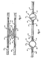
- Figure 1 is a perspective view of the delivery system described herein;
- Figure 2 is an overhead view of the delivery system
- Figure 3 is a perspective view of two delivery systems with complementary jejunal magnets
- Figure 4 is an overhead view of a dual delivery system
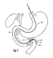
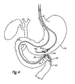
- FIGS. 5 , 6 , and 7 schematically depict the use of two magnet assemblies for forming a magnetic anastamosis device ;
- Figure 7a is a cross-sectional view of two magnets compressing the walls of two internal bodily organs to facilitate a new anastamosis
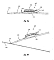
- Figures 8a and 8b are perspective views of a delivery system for delivering a magnetic anastomosis device ;
- Figures 9 is an overhead view of a delivery system for delivering a magnetic anastomosis device.
- prosthesis means any replacement for a body part or for a function of that body part or any device that enhances or adds functionality to a physiological system.
- catheter generally means a medical device comprising an elongate shaft having a lumen extending at least partially therethrough, including balloon catheters, guide catheters, and delivery catheters.
- An example of a catheter includes the Cook Medica) Fusion TM Biliary Dilation Catheter (FS-BDC).
- the magnet delivery system uses a catheter 35 and a wire guide 33 to deliver a jejunal magnet 30.
- the catheter 35 has two ports, a first port 27 and a second port 29 in communication with the lumen of the catheter and through which the wire guide 33 is placed.
- Suitable wire guides can include the Cook Medical Tracer Hybrid@ Wire Guides (HYB-48015).
- the proximal 27 and distal 29 ports are sufficiently spaced apart to accommodate the magnet 30 between them.
- the ports 27, 29 are about 35 mm to about 70 mm apart or any combination or subcombination of ranges therein. In the particular embodiment illustrated, the ports 27, 29 can be spaced about 60 mm apart.
- the first and second ports 27, 29 are formed through the catheter 35 wall and are spaced proximally from the distal end of the catheter 35 so as to be distinguished from the entry or exit openings of the catheter at the very proximal or distal ends thereof.
- the ports 27, 29 are preferably longitudinally aligned. The preferred distance between the ports will depend on the diameter and size of the magnets. Magnet sizes will range across standard sizes used in the field.
- These ports 27, 29 are located in the distal part of the catheter 35 and are appropriately spaced to accommodate magnets of various sizes in diameter. Magnets between about 10 mm and 20 mm in diameter or any combination or subcombination of ranges therein may be accommodated, although a magnet about 14 mm in diameter is illustrated. For other magnet sizes the location of the ports in the wire guide lumen may be modified as required.
- the magnet 30 shown has a general disc shape (i.e. having an axial height which is less than the outer diameter). Magnets that may be used in this delivery system can be circular, cubular, cyclindrical, polygonal, oval or ovoid, square, or the like. Numerous other shapes of the magnets may be readily . envisioned by those skilled in the art.
- the magnet may includean an elongate magnet as described in U.S. Patent Application Publication No. 2011/160752 A1 , entitled Elongate Magnet for a Magnetic Anastomosis Device".
- the magnet 30 may include a protective coating which may be formed of various materials such as polymers like Teflon® or Paralene® for protection of the magnetic core from the corrosive effects of digestive acids or other bodily fluids depending upon the bodily structure involved.
- the magnet 30 has a lumen therethrough to accommodate the wire guide 33.
- the magnet 30 also comprises an annular edge 39 along the magnet's perimeter.
- the edge 39 is slightly raised above the center of the magnet 30 such that it forms a basin 32 to accommodate or mate with a second magnet (as described below).
- this edge 39 contacts the wall of the viscera and helps to initiate the ischemic necrosis of the tissue captured between the magnet 30 and a mated second magnet.
- a radiopaque marker 37 is placed on the catheter in the vicinity of the magnet to mark the magnet location when viewed through fluoroscopy.
- a radiopaque marker can be placed underneath the magnet 30 on the catheter 35 to mark the location of the magnet when viewing the delivery system from the side.
- the wire guide 33 holds the magnet 30 in place on the distal end of the catheter 35.
- the wire guide 33 is shown protruding from the first port 27, going through the lumen of the magnet 30, and re-entering the catheter 35 at the second port 29.
- the catheter 35 may include radiopaque markers 37 that permit tracking of the delivery system for accurate positioning of the magnet 30. It may be preferred that a radiopaque marker 37 be placed immediately distal to the magnet 30.
- the catheter 35 may be used alone or in conjunction with other wire guide cannulae for navigation of the bodily lumens and delivery of a magnet.
- Figure 3 shows two delivery systems where a second magnet 31 is affixed to a second catheter 45.
- the second magnet 31 has an annular recess 40 that is capable of mating with the annular edge 39 of the first magnet 30.
- Figure 7a shows the walls 52, 62 of two viscera being compressed between magnets 30, 31.
- the edge 39 compresses the walls against the second magnet 31 to assist the ischemic necrosis.
- the second magnet 31 can also have an annular edge with a smaller diameter than the first magnet 30. When implanted and mated with the first magnet 30, the second magnet 31 can fit within the annular edge 39 of the first magnet 30.
- Figure 4 shows a system for the delivery of two magnets 30, 31. Such a system may be used as an efficient means of delivering multiple magnets.
- the catheter has four holes in total: first 57 and second 67 proximal ports and first 59 and second 69 distal ports.
- First magnet 30 is held between first port 57 and second port 59 with wire guide 33.
- the second magnet 31 is constrained between first port 67 and second port 69 with wire guide 33.
- the first magnet 30 comprises an annular edge 39 with a basin 32.
- the annular recess 40 on the second magnet 31 mates with the annular edge 39 of the first magnet 30 when both magnets 30, 31 are implanted.
- Two sets of radiopaque markers can be used with a second radiopaque marker located distal to the second magnet 31.
- the radiopaque markers can be located on the delivery portion sufficient to guide an operator during the placement procedure. Methods for delivering both magnets using such a system are described further below.
- the magnetic anastamosis device employing the magnet assemblies described herein not only preserves the benefits of improving the time of the procedure to place the magnet, but further provides a small delivery configuration which may be easily located within the body for accurate delivery.
- the delivery systems described herein also provide for insertion of the magnets through natural orifices.
- Figure 5 shows the relative positions of several viscera in the abdominal cavity, including the gall bladder 10, the common bile duct 12, the stomach 14, the duodenum 16, and the jejunum 18 of the small intestine.
- the delivery system described herein may also be used to implant anastomosis-forming magnets in the colon for possible use in gastric bypass procedures.
- the delivery system described herein can be used, for example, to create an anastomosis between the stomach 14 and the jejunum 18 of the small intestine.
- the delivery system can also be used as a part of procedure where forceps are used to place one of the magnets.
- the exemplary method for delivering a jejunal magnet to form an anastomosis comprises introducing the delivery system 65 into an endoluminal vessel.
- Figure 5 shows the system 65 being advanced to the jejunum 18.
- the delivery of magnet 31 follows once the wire guide 60 has been positioned adjacent the wall of a first viscus.
- the first viscus is the jejunum 18.
- the magnet 31 is placed on catheter 35 as shown in Figure 1 and held in place on the catheter 35 by the wire guide 33.
- the wire guide 33 is loaded through the catheter 35, passing through second port 29 in the catheter 35 lumen, through the lumen of the magnet 30, and then reentering the catheter 35 lumen through first port 27.
- the catheter 35 is advanced such that the magnet 31 is placed adjacent to the wall of the jejunum 18 as shown in Figure 6 .
- the delivery system 65 with magnet 31 remains in position as a second delivery system 70 is introduced into the stomach 14 as shown in Figure 6 .
- Magnet 30 is positioned adjacent the wall of the stomach 14 that borders the jejunum 18 near the location of magnet 31. Magnets 30, 31 are released so that the magnetic forces attract the magnets together, compressing the walls 52, 62 together of the jejunum 18 and the stomach 14 as seen in Figure 7 .
- the operator removes the wire guide 33 and then the catheter 35.
- the attraction forces exerted between the magnets 30, 31 is strong enough so that in the event that the catheter 35 is caught between the two magnets 30, 31 after the placement of magnet 30, the catheter 35 may be removed and the magnets 30, 31 will remain together.
- the radiopaque markers 37 can be used as a guide to help position the magnet 31 in the correct orientation under fluoroscopy.
- a radiopaque marker 37 may be located at the proximal edge of the magnet as exemplified in Figure 1 .
- an anastomosis is formed.
- the magnets 30, 31 can then pass through the body naturally or can be removed by means such as laparotic removal, endoscopic removal, or other procedure.
- the delivery system shown in Figure 4 can be used to deliver two magnets using one catheter.
- Magnet 31 can be delivered first to a first location to be treated by retracting the guidewire 33 sufficiently to release the magnet 31.
- the delivery portion of the catheter can then be positioned in a second location where magnet 30 can be released by further retracting the guidewire 33 from the lumen of the magnet 30.
- the magnets 30, 31 can be maneuvered to mate with one another by massage under fluoroscopy or by grasping forceps through laparoscopic surgery. Once mated, the ischemic necrosis process can begin on the walls of the two viscera being treated.
- FIGs 8a and 8b depict an alternative embodiment of a delivery system 165 in accordance with the teachings of the present description and having a description similar to that of Figure 1 , and in which similar components are denoted by similar reference numerals increased by 100.
- the delivery system 165 uses a catheter 135 with ports 127 and 129 and a wire guide 133 to deliver a magnet 130.
- the wire guide 133 includes a loop 134 at a distal end thereof. The loop 134 extends beyond a distal end of the catheter 135.
- the loop 134 slides over a second wire guide 143 during delivery of the magnet 130.
- the wire guide 143 is positioned in the target site.
- the catheter 135 is then backloaded onto the wire guide 143 via the loop 134.
- the loop 134 slidably receives the wire guide 143 and the catheter 135 is pushed relative thereto until the target site is reached.
- the magnet 130 is then placed adjacent a bodily wall.
- Another magnet is delivered in the same fashion to another target site to mate with the magnet 130 to compress the bodily walls therebetween.
- the wire guide 143 is removed followed by removal of the wire guide 133. Thereafter, the catheter 135 is removed.
- an elongate magnet 130 as described in U.S. Patent Application Publication No. 2011/160752 A1 shown.
- the elongate magnet 130 may or may not include the suture 136 shown extending through the lumen of the magnet 130 which may aid in positioning of the magnet 130.
- the delivery system 165 is advantageous for delivering larger, elongate magnets 130.
- the delivery systems described above may be used to deliver the elongate magnet 130.
- a greater force would be needed to advance the elongate magnet 130 over the wire guide 33 due to the larger area of friction between the elongate magnet 130 and the catheter 35.
- the extra force is eliminated as the magnet 130 moves with the catheter 135 as it slides along the external wire guide 143.
- Figure 9 depicts another embodiment of a delivery system 265 in accordance with the teachings of the present description and having a description similar to that of Figure 1 , and in which similar components are denoted by similar reference numerals increased by 200.
- the delivery system 265 uses a catheter 235 and a wire guide 233 to deliver a magnet 230.
- the distal loop 234 of the wire guide 233 slidably receives a second wire guide 243, similar to Figures 8a and 8b , thus providing reduced force needing during delivery of the magnet 230.
- a dual lumen outer sheath 238 slidably receives the catheter 235 in one lumen and the wire guide 233 in a second lumen.
- the outer sheath 238 includes ports 227 and 229.
- a larger portion of the catheter 235 remains closer to the wire guide 243 rather than merely the distal end as is the case with the system 165 of Figures 8a and 8b . This improves the trackability of the catheter 235 and reduces the likelihood that the catheter will bow in the stomach.
- the catheter 235 may include two lumens; one for the wire guide 233 to hold the magnet and the other for the main wire guide 243.
- the distal loop 234 slides over the main guide wire 243 during delivery of the magnet 230.
- the exemplary methods described above generally include placing the magnetic devices within a body adjacent two bodily walls to compress the bodily tissue between the magnetic devices and create a channel therethrough.
- the devices and exemplary methods may be used on any layer of material (e.g. fabrics, cloth, polymers, elastomers, plastics and rubber) that may or may not be associated with a human or animal body and a bodily lumen.
- the devices and exemplary methods disclosed herein can find use in laboratory and industrial settings for joining one or more layers of material that may or may not find application to the human or animal body, and likewise forming an opening in the layers of material that are not bodily tissue.
- Some examples include sewing or stitching and related manufacturing, working with synthetic tissues, connecting polymeric sheets, animal studies, and post-mortem activities.
Landscapes
- Health & Medical Sciences (AREA)
- Surgery (AREA)
- Life Sciences & Earth Sciences (AREA)
- Medical Informatics (AREA)
- Nuclear Medicine, Radiotherapy & Molecular Imaging (AREA)
- Engineering & Computer Science (AREA)
- Biomedical Technology (AREA)
- Heart & Thoracic Surgery (AREA)
- Physiology (AREA)
- Molecular Biology (AREA)
- Animal Behavior & Ethology (AREA)
- General Health & Medical Sciences (AREA)
- Public Health (AREA)
- Veterinary Medicine (AREA)
- Surgical Instruments (AREA)
- Media Introduction/Drainage Providing Device (AREA)
Claims (10)
- Magnetausbringungssystem (65, 165, 265) zum Bilden einer Anastomose, wobei das Magnetausbringungssystem (65, 165, 265) umfasst:eine erste Drahtführung (33, 133, 233);einen ersten Magneten (30, 130, 230), welcher ein Lumen dorthindurch definiert,dadurch gekennzeichnet, dassdas Ausbringungssystem (65, 165, 265) desweitereneinen Katheter (35, 135, 235) umfasst, welcher einen Ausbringungsabschnitt zum Fortbewegen in einen viszeralen Bereich hinein aufweist, wobei der Ausbringungsabschnitt ein erstes Katheterlumen aufweist, welches sich zumindest teilweise dorthindurch erstreckt, wobei der Ausbringungsabschnitt eine erste Öffnung (27, 127, 227) und eine zweite Öffnung (29, 129, 229) aufweist, welche mit dem ersten Katheterlumen verbunden sind und durch welche die Drahtführung (33, 133, 233) angeordnet ist,wobei der erste Magnet (30, 130, 230) durch Anordnen der Drahtführung (33, 133, 233) durch das Lumen des ersten Magneten (30, 130, 230), die erste Öffnung (27, 127, 227) und die zweite Öffnung (29, 129, 229) abnehmbar an dem Ausbringungsabschnitt des Katheters (35, 135, 235) zwischen der ersten (27, 127, 227) und der zweiten (29, 129, 229) Öffnung befestigt ist.
- Magnetausbringungssystem (65, 165, 265) nach Anspruch 1, wobei der erste Magnet (30, 130, 230) eine Scheibenform aufweist.
- Magnetausbringungssystem (65, 165, 265) nach Anspruch 1, wobei der erste Magnet (30, 130, 230) desweiteren entweder einen ringförmigen Randvorsprung (39) oder eine ringförmige Aussparung (40) umfasst.
- Magnetausbringungssystem (65, 165, 265) nach Anspruch 1, wobei der erste Magnet (30, 130, 230) einen länglichen Mantel aufweist, welcher zwei magnetische Elemente umgibt, welche entlang einer Längsachse des länglichen Mantels angeordnet sind.
- Magnetausbringungssystem (65, 165, 265) nach Anspruch 1, wobei der Ausbringungsabschnitt des Katheters (35, 135, 235) desweiteren eine dritte Öffnung, eine vierte Öffnung und einen zweiten Magneten (32), durch welchen ein Lumen ausgebildet ist, umfasst, wobei der zweite Magnet (31) abnehmbar an dem Ausbringungsabschnitt des Katheters (35, 135, 235) zwischen der dritten und der vierten Öffnung befestigt ist, wobei die erste Drahtführung (33, 133, 233) durch das Lumen des zweiten Magneten (31), die dritte Öffnung und die vierte Öffnung angeordnet ist.
- Magnetausbringungssystem (65, 165, 265) nach Anspruch 5, wobei der erste Magnet (30, 130, 230) desweiteren einen ringförmigen Randvorsprung (39) umfasst und der zweite Magnet (31) desweiteren eine ringförmige Aussparung (40) umfasst.
- Magnetausbringungssystem (65, 165, 265) nach Anspruch 1, wobei der Katheter (35, 135, 235) eine schlauchförmige Wand aufweist, wobei die erste (37, 127, 227) und die zweite (29, 129, 229) Öffnung durch die schlauchförmige Wand ausgebildet sind, wobei die erste (27, 127, 227) und die zweite (29, 129, 229) Öffnung in Längsrichtung fluchten, und wobei die erste (27, 127, 227) und die zweite (29, 129, 229) Öffnung in proximaler Richtung beabstandet von einem distalen Ende des Katheters (35, 135, 235) angeordnet sind.
- Magnetausbringungssystem (65, 165, 265) nach Anspruch 1, wobei die erste Drahtführung (33, 133, 233) eine Schlaufe (134, 234) an einem distalen Ende davon aufweist, wobei das Ausbringungssystem desweiteren eine zweite Drahtführung (143, 243) umfasst, wobei die Schlaufe (134, 234) der ersten Drahtführung (33, 133, 233) derart ausgebildet ist, dass sie sich über ein distales Ende des Katheters (35, 135, 235) erstreckt, um die zweite Kabelführung (143, 243) verschiebbar aufzunehmen.
- Magnetausbringungssystem (65, 165, 265) nach Anspruch 8, wobei der Katheter (35, 135, 235) ein zweites Katheterlumen umfasst, wobei die erste Drahtführung (33, 133, 233) innerhalb des ersten Katheterlumens angeordnet ist und die zweite Drahtführung (143, 243) innerhalb des zweiten Katheterlumens angeordnet ist.
- Magnetausbringungssystem (65, 165, 265) nach Anspruch 8, desweiteren umfassend eine äußere Hülle (238), welche ein erstes Mantellumen und ein zweites Mantellumen aufweist, wobei der Katheter (35, 135, 235) in dem ersten Lumen angeordnet ist, die erste Drahtführung (33, 133, 233) innerhalb des ersten Katheterlumens angeordnet ist und die zweite Drahtführung (143, 243) innerhalb des zweiten Mantellumens angeordnet ist.
Applications Claiming Priority (2)
| Application Number | Priority Date | Filing Date | Title |
|---|---|---|---|
| US16645309P | 2009-04-03 | 2009-04-03 | |
| PCT/US2010/029801 WO2010115116A1 (en) | 2009-04-03 | 2010-04-02 | Delivery system for magnetic anastomosis device |
Publications (2)
| Publication Number | Publication Date |
|---|---|
| EP2413813A1 EP2413813A1 (de) | 2012-02-08 |
| EP2413813B1 true EP2413813B1 (de) | 2013-08-14 |
Family
ID=42225274
Family Applications (1)
| Application Number | Title | Priority Date | Filing Date |
|---|---|---|---|
| EP10712287.1A Active EP2413813B1 (de) | 2009-04-03 | 2010-04-02 | Abgabesystem für eine magnetische anastomose-vorrichtung |
Country Status (6)
| Country | Link |
|---|---|
| US (1) | US8628548B2 (de) |
| EP (1) | EP2413813B1 (de) |
| JP (1) | JP5449525B2 (de) |
| AU (1) | AU2010232488B2 (de) |
| CA (1) | CA2757558C (de) |
| WO (1) | WO2010115116A1 (de) |
Cited By (4)
| Publication number | Priority date | Publication date | Assignee | Title |
|---|---|---|---|---|
| CN106061408A (zh) * | 2013-12-31 | 2016-10-26 | 伊兹诺茨有限公司 | 磁吻合组件 |
| US10154844B2 (en) | 2016-07-25 | 2018-12-18 | Virender K. Sharma | Magnetic anastomosis device and delivery system |
| US10561423B2 (en) | 2016-07-25 | 2020-02-18 | Virender K. Sharma | Cardiac shunt device and delivery system |
| US11304698B2 (en) | 2016-07-25 | 2022-04-19 | Virender K. Sharma | Cardiac shunt device and delivery system |
Families Citing this family (15)
| Publication number | Priority date | Publication date | Assignee | Title |
|---|---|---|---|---|
| CA2746083C (en) | 2007-12-21 | 2016-02-23 | Medical And Surgical Review, P.C. | Methods and devices for endoscopically creating an anastomosis |
| AU2009209518A1 (en) * | 2008-01-28 | 2009-08-06 | Milux Holding S.A. | A drainage device comprising an active filter |
| US8679139B2 (en) | 2009-04-03 | 2014-03-25 | Cook Medical Technologies Llc | Delivery system for magnetic anastomosis device |
| EP2413813B1 (de) | 2009-04-03 | 2013-08-14 | Cook Medical Technologies LLC | Abgabesystem für eine magnetische anastomose-vorrichtung |
| AU2010247862B2 (en) * | 2009-05-15 | 2013-02-07 | Cook Medical Technologies Llc | Delivery system for magnetic anastomosis device |
| ES2898345T3 (es) * | 2009-07-15 | 2022-03-07 | Gt Metabolic Solutions Inc | Dispositivos para un baipás gástrico sin incisión |
| US8728105B2 (en) | 2009-12-30 | 2014-05-20 | Cook Medical Technologies Llc | Elongate magnet for a magnetic anastomosis device |
| US9332990B2 (en) * | 2010-12-30 | 2016-05-10 | Wake Forest University Health Sciences | Ureter to ileal conduit anastomosis using magnetic compression and related delivery devices and methods |
| EP2717789B1 (de) * | 2011-06-09 | 2017-11-15 | Cook Medical Technologies LLC | Zuführsystem für eine magnetische anastomosevorrichtung |
| WO2013070838A1 (en) | 2011-11-09 | 2013-05-16 | Easynotes Ltd. | Obstruction device |
| US20130325042A1 (en) * | 2012-05-31 | 2013-12-05 | Izhak Fabian | Pylorus plug and anastomosis |
| US9125660B2 (en) | 2013-04-14 | 2015-09-08 | Easynotes Ltd. | Inflation and deflation of obstruction device |
| US20140309669A1 (en) * | 2013-04-14 | 2014-10-16 | Izhak Fabian | Positioning tool for anastomosis |
| US20160000985A1 (en) * | 2014-07-02 | 2016-01-07 | Abbott Cardiovascular Systems Inc. | Extravascular devices supporting an arteriovenous fistula |
| US9943335B2 (en) | 2014-09-23 | 2018-04-17 | Cook Medical Technologies Llc | Implanted magnets retrieval system and method |
Family Cites Families (12)
| Publication number | Priority date | Publication date | Assignee | Title |
|---|---|---|---|---|
| US5690656A (en) | 1995-06-27 | 1997-11-25 | Cook Incorporated | Method and apparatus for creating abdominal visceral anastomoses |
| US6352543B1 (en) * | 2000-04-29 | 2002-03-05 | Ventrica, Inc. | Methods for forming anastomoses using magnetic force |
| US6273917B1 (en) * | 1998-03-27 | 2001-08-14 | Kanji Inoue | Transplantation device |
| US20050080439A1 (en) * | 2000-04-29 | 2005-04-14 | Carson Dean F. | Devices and methods for forming magnetic anastomoses and ports in vessels |
| US6802847B1 (en) * | 2000-04-29 | 2004-10-12 | Ventrica, Inc. | Devices and methods for forming magnetic anastomoses and ports in vessels |
| US7025791B2 (en) * | 2002-12-02 | 2006-04-11 | Gi Dynamics, Inc. | Bariatric sleeve |
| JP4898985B2 (ja) * | 2003-07-31 | 2012-03-21 | クック メディカル テクノロジーズ エルエルシー | 複数の医療装置を導入するためのシステム及び方法 |
| US7282057B2 (en) * | 2004-03-30 | 2007-10-16 | Wilson-Cook Medical, Inc. | Pediatric atresia magnets |
| EP2086426B1 (de) * | 2006-11-10 | 2013-07-31 | Cook Medical Technologies LLC | Ringmagneten für chirurgische verfahren |
| EP2207488B1 (de) * | 2007-10-09 | 2012-09-26 | Cook Medical Technologies LLC | Magnetische anastomosevorrichtung mit verbesserter freisetzung |
| US8679139B2 (en) * | 2009-04-03 | 2014-03-25 | Cook Medical Technologies Llc | Delivery system for magnetic anastomosis device |
| EP2413813B1 (de) | 2009-04-03 | 2013-08-14 | Cook Medical Technologies LLC | Abgabesystem für eine magnetische anastomose-vorrichtung |
-
2010
- 2010-04-02 EP EP10712287.1A patent/EP2413813B1/de active Active
- 2010-04-02 CA CA2757558A patent/CA2757558C/en active Active
- 2010-04-02 AU AU2010232488A patent/AU2010232488B2/en active Active
- 2010-04-02 WO PCT/US2010/029801 patent/WO2010115116A1/en active Application Filing
- 2010-04-02 US US12/753,583 patent/US8628548B2/en active Active
- 2010-04-02 JP JP2012503745A patent/JP5449525B2/ja active Active
Cited By (4)
| Publication number | Priority date | Publication date | Assignee | Title |
|---|---|---|---|---|
| CN106061408A (zh) * | 2013-12-31 | 2016-10-26 | 伊兹诺茨有限公司 | 磁吻合组件 |
| US10154844B2 (en) | 2016-07-25 | 2018-12-18 | Virender K. Sharma | Magnetic anastomosis device and delivery system |
| US10561423B2 (en) | 2016-07-25 | 2020-02-18 | Virender K. Sharma | Cardiac shunt device and delivery system |
| US11304698B2 (en) | 2016-07-25 | 2022-04-19 | Virender K. Sharma | Cardiac shunt device and delivery system |
Also Published As
| Publication number | Publication date |
|---|---|
| CA2757558C (en) | 2014-05-20 |
| AU2010232488A1 (en) | 2011-11-10 |
| CA2757558A1 (en) | 2010-10-07 |
| JP2012522601A (ja) | 2012-09-27 |
| US20100256659A1 (en) | 2010-10-07 |
| US8628548B2 (en) | 2014-01-14 |
| JP5449525B2 (ja) | 2014-03-19 |
| EP2413813A1 (de) | 2012-02-08 |
| WO2010115116A1 (en) | 2010-10-07 |
| AU2010232488B2 (en) | 2013-10-17 |
Similar Documents
| Publication | Publication Date | Title |
|---|---|---|
| EP2413813B1 (de) | Abgabesystem für eine magnetische anastomose-vorrichtung | |
| EP2429625B1 (de) | Freisetzungssystem für eine magnetische anastomosevorrichtung | |
| US8679139B2 (en) | Delivery system for magnetic anastomosis device | |
| US11612398B2 (en) | Incisionless gastric bypass system | |
| US8262680B2 (en) | Anastomotic device | |
| EP2717789B1 (de) | Zuführsystem für eine magnetische anastomosevorrichtung |
Legal Events
| Date | Code | Title | Description |
|---|---|---|---|
| PUAI | Public reference made under article 153(3) epc to a published international application that has entered the european phase |
Free format text: ORIGINAL CODE: 0009012 |
|
| 17P | Request for examination filed |
Effective date: 20111017 |
|
| AK | Designated contracting states |
Kind code of ref document: A1 Designated state(s): AT BE BG CH CY CZ DE DK EE ES FI FR GB GR HR HU IE IS IT LI LT LU LV MC MK MT NL NO PL PT RO SE SI SK SM TR |
|
| DAX | Request for extension of the european patent (deleted) | ||
| GRAC | Information related to communication of intention to grant a patent modified |
Free format text: ORIGINAL CODE: EPIDOSCIGR1 |
|
| GRAP | Despatch of communication of intention to grant a patent |
Free format text: ORIGINAL CODE: EPIDOSNIGR1 |
|
| GRAP | Despatch of communication of intention to grant a patent |
Free format text: ORIGINAL CODE: EPIDOSNIGR1 |
|
| GRAS | Grant fee paid |
Free format text: ORIGINAL CODE: EPIDOSNIGR3 |
|
| GRAA | (expected) grant |
Free format text: ORIGINAL CODE: 0009210 |
|
| AK | Designated contracting states |
Kind code of ref document: B1 Designated state(s): AT BE BG CH CY CZ DE DK EE ES FI FR GB GR HR HU IE IS IT LI LT LU LV MC MK MT NL NO PL PT RO SE SI SK SM TR |
|
| REG | Reference to a national code |
Ref country code: GB Ref legal event code: FG4D |
|
| REG | Reference to a national code |
Ref country code: AT Ref legal event code: REF Ref document number: 626303 Country of ref document: AT Kind code of ref document: T Effective date: 20130815 Ref country code: CH Ref legal event code: EP |
|
| REG | Reference to a national code |
Ref country code: IE Ref legal event code: FG4D |
|
| REG | Reference to a national code |
Ref country code: DE Ref legal event code: R096 Ref document number: 602010009422 Country of ref document: DE Effective date: 20131010 |
|
| REG | Reference to a national code |
Ref country code: NL Ref legal event code: VDEP Effective date: 20130814 Ref country code: AT Ref legal event code: MK05 Ref document number: 626303 Country of ref document: AT Kind code of ref document: T Effective date: 20130814 |
|
| REG | Reference to a national code |
Ref country code: LT Ref legal event code: MG4D |
|
| PG25 | Lapsed in a contracting state [announced via postgrant information from national office to epo] |
Ref country code: SE Free format text: LAPSE BECAUSE OF FAILURE TO SUBMIT A TRANSLATION OF THE DESCRIPTION OR TO PAY THE FEE WITHIN THE PRESCRIBED TIME-LIMIT Effective date: 20130814 Ref country code: LT Free format text: LAPSE BECAUSE OF FAILURE TO SUBMIT A TRANSLATION OF THE DESCRIPTION OR TO PAY THE FEE WITHIN THE PRESCRIBED TIME-LIMIT Effective date: 20130814 Ref country code: AT Free format text: LAPSE BECAUSE OF FAILURE TO SUBMIT A TRANSLATION OF THE DESCRIPTION OR TO PAY THE FEE WITHIN THE PRESCRIBED TIME-LIMIT Effective date: 20130814 Ref country code: PT Free format text: LAPSE BECAUSE OF FAILURE TO SUBMIT A TRANSLATION OF THE DESCRIPTION OR TO PAY THE FEE WITHIN THE PRESCRIBED TIME-LIMIT Effective date: 20131216 Ref country code: IS Free format text: LAPSE BECAUSE OF FAILURE TO SUBMIT A TRANSLATION OF THE DESCRIPTION OR TO PAY THE FEE WITHIN THE PRESCRIBED TIME-LIMIT Effective date: 20131214 Ref country code: HR Free format text: LAPSE BECAUSE OF FAILURE TO SUBMIT A TRANSLATION OF THE DESCRIPTION OR TO PAY THE FEE WITHIN THE PRESCRIBED TIME-LIMIT Effective date: 20130814 Ref country code: NO Free format text: LAPSE BECAUSE OF FAILURE TO SUBMIT A TRANSLATION OF THE DESCRIPTION OR TO PAY THE FEE WITHIN THE PRESCRIBED TIME-LIMIT Effective date: 20131114 Ref country code: CY Free format text: LAPSE BECAUSE OF FAILURE TO SUBMIT A TRANSLATION OF THE DESCRIPTION OR TO PAY THE FEE WITHIN THE PRESCRIBED TIME-LIMIT Effective date: 20130807 |
|
| PG25 | Lapsed in a contracting state [announced via postgrant information from national office to epo] |
Ref country code: BE Free format text: LAPSE BECAUSE OF FAILURE TO SUBMIT A TRANSLATION OF THE DESCRIPTION OR TO PAY THE FEE WITHIN THE PRESCRIBED TIME-LIMIT Effective date: 20130814 Ref country code: GR Free format text: LAPSE BECAUSE OF FAILURE TO SUBMIT A TRANSLATION OF THE DESCRIPTION OR TO PAY THE FEE WITHIN THE PRESCRIBED TIME-LIMIT Effective date: 20131115 Ref country code: FI Free format text: LAPSE BECAUSE OF FAILURE TO SUBMIT A TRANSLATION OF THE DESCRIPTION OR TO PAY THE FEE WITHIN THE PRESCRIBED TIME-LIMIT Effective date: 20130814 Ref country code: SI Free format text: LAPSE BECAUSE OF FAILURE TO SUBMIT A TRANSLATION OF THE DESCRIPTION OR TO PAY THE FEE WITHIN THE PRESCRIBED TIME-LIMIT Effective date: 20130814 Ref country code: LV Free format text: LAPSE BECAUSE OF FAILURE TO SUBMIT A TRANSLATION OF THE DESCRIPTION OR TO PAY THE FEE WITHIN THE PRESCRIBED TIME-LIMIT Effective date: 20130814 Ref country code: PL Free format text: LAPSE BECAUSE OF FAILURE TO SUBMIT A TRANSLATION OF THE DESCRIPTION OR TO PAY THE FEE WITHIN THE PRESCRIBED TIME-LIMIT Effective date: 20130814 |
|
| PG25 | Lapsed in a contracting state [announced via postgrant information from national office to epo] |
Ref country code: CY Free format text: LAPSE BECAUSE OF FAILURE TO SUBMIT A TRANSLATION OF THE DESCRIPTION OR TO PAY THE FEE WITHIN THE PRESCRIBED TIME-LIMIT Effective date: 20130814 |
|
| PG25 | Lapsed in a contracting state [announced via postgrant information from national office to epo] |
Ref country code: SK Free format text: LAPSE BECAUSE OF FAILURE TO SUBMIT A TRANSLATION OF THE DESCRIPTION OR TO PAY THE FEE WITHIN THE PRESCRIBED TIME-LIMIT Effective date: 20130814 Ref country code: NL Free format text: LAPSE BECAUSE OF FAILURE TO SUBMIT A TRANSLATION OF THE DESCRIPTION OR TO PAY THE FEE WITHIN THE PRESCRIBED TIME-LIMIT Effective date: 20130814 Ref country code: CZ Free format text: LAPSE BECAUSE OF FAILURE TO SUBMIT A TRANSLATION OF THE DESCRIPTION OR TO PAY THE FEE WITHIN THE PRESCRIBED TIME-LIMIT Effective date: 20130814 Ref country code: DK Free format text: LAPSE BECAUSE OF FAILURE TO SUBMIT A TRANSLATION OF THE DESCRIPTION OR TO PAY THE FEE WITHIN THE PRESCRIBED TIME-LIMIT Effective date: 20130814 Ref country code: EE Free format text: LAPSE BECAUSE OF FAILURE TO SUBMIT A TRANSLATION OF THE DESCRIPTION OR TO PAY THE FEE WITHIN THE PRESCRIBED TIME-LIMIT Effective date: 20130814 Ref country code: RO Free format text: LAPSE BECAUSE OF FAILURE TO SUBMIT A TRANSLATION OF THE DESCRIPTION OR TO PAY THE FEE WITHIN THE PRESCRIBED TIME-LIMIT Effective date: 20130814 |
|
| PG25 | Lapsed in a contracting state [announced via postgrant information from national office to epo] |
Ref country code: ES Free format text: LAPSE BECAUSE OF FAILURE TO SUBMIT A TRANSLATION OF THE DESCRIPTION OR TO PAY THE FEE WITHIN THE PRESCRIBED TIME-LIMIT Effective date: 20130814 Ref country code: IT Free format text: LAPSE BECAUSE OF FAILURE TO SUBMIT A TRANSLATION OF THE DESCRIPTION OR TO PAY THE FEE WITHIN THE PRESCRIBED TIME-LIMIT Effective date: 20130814 |
|
| PLBE | No opposition filed within time limit |
Free format text: ORIGINAL CODE: 0009261 |
|
| STAA | Information on the status of an ep patent application or granted ep patent |
Free format text: STATUS: NO OPPOSITION FILED WITHIN TIME LIMIT |
|
| 26N | No opposition filed |
Effective date: 20140515 |
|
| REG | Reference to a national code |
Ref country code: DE Ref legal event code: R097 Ref document number: 602010009422 Country of ref document: DE Effective date: 20140515 |
|
| PG25 | Lapsed in a contracting state [announced via postgrant information from national office to epo] |
Ref country code: MC Free format text: LAPSE BECAUSE OF FAILURE TO SUBMIT A TRANSLATION OF THE DESCRIPTION OR TO PAY THE FEE WITHIN THE PRESCRIBED TIME-LIMIT Effective date: 20130814 Ref country code: LU Free format text: LAPSE BECAUSE OF FAILURE TO SUBMIT A TRANSLATION OF THE DESCRIPTION OR TO PAY THE FEE WITHIN THE PRESCRIBED TIME-LIMIT Effective date: 20140402 |
|
| REG | Reference to a national code |
Ref country code: CH Ref legal event code: PL |
|
| REG | Reference to a national code |
Ref country code: FR Ref legal event code: ST Effective date: 20141231 |
|
| PG25 | Lapsed in a contracting state [announced via postgrant information from national office to epo] |
Ref country code: CH Free format text: LAPSE BECAUSE OF NON-PAYMENT OF DUE FEES Effective date: 20140430 Ref country code: LI Free format text: LAPSE BECAUSE OF NON-PAYMENT OF DUE FEES Effective date: 20140430 |
|
| PG25 | Lapsed in a contracting state [announced via postgrant information from national office to epo] |
Ref country code: FR Free format text: LAPSE BECAUSE OF NON-PAYMENT OF DUE FEES Effective date: 20140430 |
|
| PG25 | Lapsed in a contracting state [announced via postgrant information from national office to epo] |
Ref country code: MT Free format text: LAPSE BECAUSE OF FAILURE TO SUBMIT A TRANSLATION OF THE DESCRIPTION OR TO PAY THE FEE WITHIN THE PRESCRIBED TIME-LIMIT Effective date: 20130814 |
|
| PG25 | Lapsed in a contracting state [announced via postgrant information from national office to epo] |
Ref country code: SM Free format text: LAPSE BECAUSE OF FAILURE TO SUBMIT A TRANSLATION OF THE DESCRIPTION OR TO PAY THE FEE WITHIN THE PRESCRIBED TIME-LIMIT Effective date: 20130814 |
|
| PG25 | Lapsed in a contracting state [announced via postgrant information from national office to epo] |
Ref country code: BG Free format text: LAPSE BECAUSE OF FAILURE TO SUBMIT A TRANSLATION OF THE DESCRIPTION OR TO PAY THE FEE WITHIN THE PRESCRIBED TIME-LIMIT Effective date: 20130814 |
|
| PG25 | Lapsed in a contracting state [announced via postgrant information from national office to epo] |
Ref country code: TR Free format text: LAPSE BECAUSE OF FAILURE TO SUBMIT A TRANSLATION OF THE DESCRIPTION OR TO PAY THE FEE WITHIN THE PRESCRIBED TIME-LIMIT Effective date: 20130814 Ref country code: HU Free format text: LAPSE BECAUSE OF FAILURE TO SUBMIT A TRANSLATION OF THE DESCRIPTION OR TO PAY THE FEE WITHIN THE PRESCRIBED TIME-LIMIT; INVALID AB INITIO Effective date: 20100402 |
|
| PG25 | Lapsed in a contracting state [announced via postgrant information from national office to epo] |
Ref country code: MK Free format text: LAPSE BECAUSE OF FAILURE TO SUBMIT A TRANSLATION OF THE DESCRIPTION OR TO PAY THE FEE WITHIN THE PRESCRIBED TIME-LIMIT Effective date: 20130814 |
|
| P01 | Opt-out of the competence of the unified patent court (upc) registered |
Effective date: 20230602 |
|
| PGFP | Annual fee paid to national office [announced via postgrant information from national office to epo] |
Ref country code: DE Payment date: 20230320 Year of fee payment: 14 |
|
| PGFP | Annual fee paid to national office [announced via postgrant information from national office to epo] |
Ref country code: IE Payment date: 20240326 Year of fee payment: 15 |
|
| PGFP | Annual fee paid to national office [announced via postgrant information from national office to epo] |
Ref country code: GB Payment date: 20240314 Year of fee payment: 15 |