EP2413690B1 - A fixed spool fishing reel - Google Patents
A fixed spool fishing reel Download PDFInfo
- Publication number
- EP2413690B1 EP2413690B1 EP10719599.2A EP10719599A EP2413690B1 EP 2413690 B1 EP2413690 B1 EP 2413690B1 EP 10719599 A EP10719599 A EP 10719599A EP 2413690 B1 EP2413690 B1 EP 2413690B1
- Authority
- EP
- European Patent Office
- Prior art keywords
- shaft
- gear
- handle
- spool
- teeth
- Prior art date
- Legal status (The legal status is an assumption and is not a legal conclusion. Google has not performed a legal analysis and makes no representation as to the accuracy of the status listed.)
- Not-in-force
Links
Images


Classifications
-
- A—HUMAN NECESSITIES
- A01—AGRICULTURE; FORESTRY; ANIMAL HUSBANDRY; HUNTING; TRAPPING; FISHING
- A01K—ANIMAL HUSBANDRY; CARE OF BIRDS, FISHES, INSECTS; FISHING; REARING OR BREEDING ANIMALS, NOT OTHERWISE PROVIDED FOR; NEW BREEDS OF ANIMALS
- A01K89/00—Reels
- A01K89/01—Reels with pick-up, i.e. with the guiding member rotating and the spool not rotating during normal retrieval of the line
- A01K89/0105—Multi-speed mechanisms
-
- A—HUMAN NECESSITIES
- A01—AGRICULTURE; FORESTRY; ANIMAL HUSBANDRY; HUNTING; TRAPPING; FISHING
- A01K—ANIMAL HUSBANDRY; CARE OF BIRDS, FISHES, INSECTS; FISHING; REARING OR BREEDING ANIMALS, NOT OTHERWISE PROVIDED FOR; NEW BREEDS OF ANIMALS
- A01K89/00—Reels
- A01K89/01—Reels with pick-up, i.e. with the guiding member rotating and the spool not rotating during normal retrieval of the line
-
- Y—GENERAL TAGGING OF NEW TECHNOLOGICAL DEVELOPMENTS; GENERAL TAGGING OF CROSS-SECTIONAL TECHNOLOGIES SPANNING OVER SEVERAL SECTIONS OF THE IPC; TECHNICAL SUBJECTS COVERED BY FORMER USPC CROSS-REFERENCE ART COLLECTIONS [XRACs] AND DIGESTS
- Y10—TECHNICAL SUBJECTS COVERED BY FORMER USPC
- Y10T—TECHNICAL SUBJECTS COVERED BY FORMER US CLASSIFICATION
- Y10T74/00—Machine element or mechanism
- Y10T74/19—Gearing
- Y10T74/19219—Interchangeably locked
- Y10T74/19293—Longitudinally slidable
- Y10T74/19298—Multiple spur gears
- Y10T74/19316—Progressive
Definitions
- the present invention relates to a fixed spool fishing reel having a handle shaft connected to a handle to be rotated thereby and coupled to a bail arm drive of the reel so that rotation of the handle shaft causes rotation of the bail arm, in which the handle shaft is coupled to the bail arm drive via a gear mechanism that enables the gear ratio between rotation of the handle shaft and rotation of the bail arm drive to be selectively altered, in which the handle is readily releaseably connected to either selected one of the two ends of the handle shaft.
- Such a fishing reel is used in a sport referred to as "high speed jigging".
- high speed jigging This involves fishing at sea in which a jig comprising for example a hook, a lure and a weight at the end of a line is cast into the sea and allowed to drop whilst attached to the line many hundreds of feet below the surface of the water.
- the reel is then used to wind-in the line, thus raising the rig at high speed.
- the raising of the jig in this way attracts a fish which may bite on to the hook so that the fish may now be reeled-in.
- a disadvantage of such a fishing reel which has already been proposed is that the forces which can be exerted on the fish by the angler with such a reel are insufficient to play the fish towards the boat with reasonable ease.
- the present invention seeks to provide a remedy, although it will be appreciated that the benefit of the present invention is not restricted to high speed jigging.
- US-A-4850549 discloses a fishing spinning reel speed changer wherein the winding handle is selectively attachable to the right and left sides of the reel.
- Two first and second speed change gears are integrally engaged with large and small speed change gears and movably fitted on a clutch axially displaceable on a hollow gear shaft which is rotatably supported through the spinning reel's body.
- a clutch lever and an attached bar may readily be assembled and disengaged to and from the spinning reel body for maintenance and when rotated move the bar to engage either the first speed change gear or the second speed change gear for low or high speed rotation.
- the present invention is directed to a fixed spool fishing reel having the construction set out in the opening paragraph of the present specification, in which the handle shaft extends through a hollow dog gear shaft which is rotationally fixed on but slidable along the handle shaft, which dog gear shaft is provided with dog gears at both of its ends, couplable respectively to two gear wheels of the said gear mechanism, the length of the dog gear shaft being such that when one of its ends is coupled to its associated gear wheel the other is not, and correspondingly when the other of its ends is coupled to its associated gear wheel the said one of its ends is not.
- a fixed spool fishing reel is one in which the spool itself does not rotate. However, it does reciprocate as the bail arm rotates to lay the line evenly on to the spool.
- the two gear wheels may be on opposite sides of a spool shaft of the reel, coupling between each of the said two gear wheels and a spool shaft oscillatory mechanism of the reel being via respective gearing arrangements to impart different respective ratios of handle rotary speed to oscillatory speed of the spool shaft.
- the spool shaft may have a slot in it, and the coupling between one of the said two gear wheels and the oscillatory mechanism may be by way of a shaft which passes through the said slot.
- the hollow dog gear shaft may be moved towards and away from both of the said two gear wheels by way of a lever coupled to the dog gear shaft via a resilient member whereby each dog gear will be urged into engagement with the associated one of the said two gear wheels, and may so engage once they have an appropriate relative angular position.
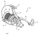
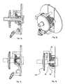
- a fixed spool fishing reel 10 shown in Figure 1 comprises a mounting foot 12, a support arm 14 extending in an intended downward direction from the mounting foot 12 to the reel housing 16, a handle 18 rotatably mounted on a crank 20 connected to the housing 16, a bail arm 22 with a bail 24, and a skirted spool 26 extending forwardly from the front of the housing 16 with its axis parallel to the foot 12 and hence to an angling rod to which the reel is attached when the latter is in use.
- crank 20 is connected to a handle shaft 34 which extends through the housing 16 transversely of the spool axis, the end of the shaft 34 that projects outwardly from the housing 16 on the crank side thereof is surrounded by a compression spring 36 located between the housing 16 and an inner end of the crank 20.
- the spring 36 is covered by a skirt portion 38 extending from the inner end of the crank 20.
- Figure 3 shows that the shaft 34 comprises a number of parts to facilitate assembly.
- a portion of the shaft 34 extending from the crank 20 has an internally screw-threaded hollow which receives an externally screw-threaded shank portion 40 extending from that portion of the shaft 34 which projects from the housing 16 on the side further from the crank 20.
- An outer end of the latter is provided with a pivot 42 to which is connected the lever 30 in such a manner that operation of the lever 30 outwardly from the housing 16 enables the shaft 34 to slide in a direction towards the crank 20 under the action of the compression spring 36.
- Movement of the user operable lever 30 back to the position it has in Figures 2 and 3 draws the shaft 34 in a direction away from the crank 20 against the action of the compression spring 36.
- a snap action (not shown) holds the lever 30 in this position until the user moves it once again to the outward position.
- the shaft 34 is provided with a sleeve 44 which is fixed relative to the portions of the shaft 34 which extend through it and which is provided with a series of splines or external teeth 46 extending around a portion of its circumference.
- these teeth 46 which are external teeth in the sense that they extend around the outside of the shaft 34, engage internal teeth of a first gear wheel 48 which surrounds the shaft 34 and is generally or substantially orthogonal thereto.
- This gear wheel 48 is fixed to and integral with a sleeve portion 50 which is coaxial with and rotatable in relation to the shaft 34.
- the sleeve portion 50 in turn is fixed to and integral with a crown wheel 52, the latter having an axis of rotation which is co-linear with the axis of the shaft 34. It is coupled to drive a further gear 54 coupled to rotate the bail arm 22.
- a second gear wheel 56 also surrounds and is generally or substantially orthogonal to the shaft 34 and is also provided with internal teeth, and external teeth which engage the gearing mechanism 32 coupled to the said first gear wheel 48. This second gear wheel 56 is immediately adjacent and on the crank side of the said first gear wheel 48.
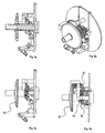
- the second embodiment is illustrated in Figures 6 to 12 .
- the gear wheels 48 and 56 are substantially and immediately adjacent to one another, such separation as there is between them being less than 10% of the width of each.
- the gear wheel 48 has internal teeth 60 and the gear wheel 56 has internal teeth 62.
- Each tooth 60 and 62 has a flat 64 facing in an anti-clockwise sense about the common axes of these wheels 48 and 56, as viewed in the manner shown in Figure 6 .
- the side of each tooth 60 which is adjacent to the wheel 56, and the side of each tooth 62 which is adjacent to the wheel 48, is chamfered or bevelled in planes which are perpendicular to the direction of extension of the tooth.
- the face of the chamfering or bevelling is directed rearwardly of the tooth and outwardly of the wheel of which the tooth is a part.
- the edges of the tooth are generally rounded to reduce the likelihood of wear and friction.
- the splines or external teeth 46 and the sleeve 44 are each provided with a flat 66 directed in a clockwise sense around the axis of the sleeve 44, and consequently also the axes of rotation of the gear wheels 48 and 56, viewing these parts in the direction of view of Figure 6 .
- each spline or external tooth 46 is generally arcuate and convex.
- the edges of the splines or external teeth 46 are rounded to reduce wear and friction.
- a flange 70 is integral with and extends around a portion of the sleeve 44 spaced to the right of the splines or external teeth 46 as viewed in Figure 6 .
- the sleeve 44 is slidable in a longitudinal direction relative to its axis so that the splines or external teeth 46 may engage the internal teeth 60 or 62 of either selected one of the two gear wheels 48 and 56.
- a mechanism to be described herein engages the flange 70 to shift the sleeve 44 to the left or to the right as viewed in Figure 6 .
- the various component parts will usually, but not necessarily, be stationary.
- the change of engagement of the splines or external teeth 46 from the internal teeth 60 of the gear wheel 48, so that the sleeve 44 is to be shifted to the right as in Figure 6 and the splines or external teeth 46 are to move into engagement with the internal teeth 62 of the gear wheel 56, will be considered first.
- the sleeve 44 is urged rightwardly to effect this change by a spring mechanism to be described herein. If the teeth 62 happen to be in registration with the teeth 60 at this stage, the sleeve 44 will move fully to the right to enable an immediate change of engagement of the teeth 46 from the teeth 60 of the wheel 48 to the teeth 62 of the wheel 56.
- the gear wheel 48 rotates faster than the, gear wheel 56. If, therefore, at the time of switching, the teeth 62 and the teeth 60 are not in registration with one another, the teeth 46 will slide towards the teeth 62 so that they engage the chamfered or bevelled sides of the teeth 62, until full engagement of the teeth 46 with the teeth 62 is possible when the teeth 60 are next in registration with the teeth 62.
- the teeth 60 are positioned slightly ahead of the teeth 62 in a clockwise sense, the teeth 46 will slide towards the gap between the teeth 60 until a slanting rear flank of each tooth 46 abuts the chamfered or bevelled side of an adjacent tooth 60. From here, further rotation of the sleeve 44 by the crank 20 will cause the teeth 46 to rotate the wheel 56, and consequently through the gear mechanism 32 the wheel 48 at a faster rate so that each tooth 60 will catch up and overtake the adjacent tooth 62.
- the teeth 46 are first pushed out of the gaps between the teeth 60 by virtue of the chamfered or bevelled sides thereof until the face 64 of each tooth 60 passes the flat face 66 of the adjacent tooth 46, whereupon the latter is now free to slide in the adjacent gap between teeth 60 so that the teeth 46 now fully engage the teeth 60.
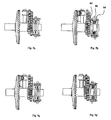
- a shift member 80 extends above the and below the sleeve 44. It has inner portions 82 which are sandwiched between plates 84 and has a pair of spigots 86 projecting outwardly from opposite sides of the switching member 80. The plates 84 are connected together by tension springs 88. The flange 70 of the sleeve 44 is also sandwiched between the plates 84.
- a stirrup 90 is provided with two sides 92 which extend on opposite sides of the sleeve 44. Each side 92 is provided with a pair of elongate apertures 94, which slant in relation to a plane perpendicular to the axis of the sleeve 44. The spigots 84 extend into the slanting apertures 94.
- a user operable lever 96 is pivotally attached to the underside of the housing 16 in Figure 1 so as to be pivotable to the left or to the right viewing the reel along the direction of the axis of the spool 26, or in the direction of view of Figures 11 and 12 for example.
- a mechanical link 98 couples the lever 96 to the stirrup 90 such that viewing the parts as shown in Figure 11 for example a pivoting movement of the lever 96 from the left to the right lowers the stirrup 90, thus moving it transversely of the axis of the sleeve 44, and slides the switching member 80 to the left, and thus longitudinally in relation to the axis of the sleeve 44, whereas movement of the lever to the left moves these various parts in the respective opposite directions.
- the movement of the switching member 80 for example from its left-hand position as viewed in Figure 11 to its right-hand position as viewed in Figure 11 is the step represented by the change from Figure 11 a to Figure 11 b .
- the sleeve 44 has a wider cross-section at one end than at the other in Figures 6 to 12 , it is preferable for that sleeve to be formed so that it has hollows at least at both its ends of the same internal cross-section. These cross-sections are both non-circular. Rotatable spigots (not shown) having the same external cross-section as the internal cross-section of these hollows extend respectively from the crank 20 and a securing portion on the opposite side of the housing 16.
- a tranverse axle 100 can be connected by releasable connection devices (not shown) to the handle 18 selectively at either one of its two ends, to provide a right- or left-handed reel.
- Two gear wheels 102 and 104 of different respective diameters are attached to this axle 100 so as to be in respective spaced apart fixed positions on the axle 100, but also so as to be rotatable relative thereto and also therewith.
- a spool shaft 106 to which the spool 26 is attached extends at right angles to the axle 100, longitudinally of the reel.
- the two gear wheels 102 and 104 are on opposite respective sides of the spool shaft 106.
- the gear wheel 102 meshes directly with an oscillatory motion mechanism drive wheel 108.
- the gear wheel 104 is coupled to drive the wheel 108 via a gear train 110, the end gear wheel 112 of which is rotationally fixed to and is coaxial with the wheel 108.
- the wheels 112 and 108 are fixed together by way of a transverse shaft 114 which extends through a slot 116 which is in and extends longitudinally along the spool shaft 106.
- a block 118 at the end of the spool shaft 106 which is further from the spool 26 is formed with an S-slot 119 which receives a spigot 121 on the side of an oscillatory motion effecting wheel 120 coupled to be driven by the wheel 108.
- the wheel 108 is also coupled to drive a bevelled gear 122 itself coupled to rotate the bail arm 22 whilst the spool 26 is being moved forwards and backwards by the oscillating mechanism.
- a hollow shaft 124 at opposite ends of which are respective dog gears 126 and 128.
- the length of the shaft 124 is such that when the dog gear 126 is coupled to the gear wheel 102, the dog gear is uncoupled from the gear wheel 104, and vice versa.
- a slideable bracket 130 below the shaft 124 can be moved transversely by the user by means of a lever 132 linked to the bracket 130.
- a helical compression spring 133 is located relative to the bracket in such a fashion that when the lever 132 is operated, the shaft 124 is urged in a direction to change gear, but the gear is only actually changed when the relevant dog gear meshes with a part of the relevant one of the said two gears 102 and 104.
- switching the lever 132 thereby changes the gearing between spool oscillation speed and bail arm speed on the one hand and the speed with which the handle 18 is rotated on the other hand.
- the two ratios either one of which can be selected are 6.5:1 and 2:1.
Description
- The present invention relates to a fixed spool fishing reel having a handle shaft connected to a handle to be rotated thereby and coupled to a bail arm drive of the reel so that rotation of the handle shaft causes rotation of the bail arm, in which the handle shaft is coupled to the bail arm drive via a gear mechanism that enables the gear ratio between rotation of the handle shaft and rotation of the bail arm drive to be selectively altered, in which the handle is readily releaseably connected to either selected one of the two ends of the handle shaft.
- Such a fishing reel is used in a sport referred to as "high speed jigging". This involves fishing at sea in which a jig comprising for example a hook, a lure and a weight at the end of a line is cast into the sea and allowed to drop whilst attached to the line many hundreds of feet below the surface of the water. The reel is then used to wind-in the line, thus raising the rig at high speed. The raising of the jig in this way attracts a fish which may bite on to the hook so that the fish may now be reeled-in.
- A disadvantage of such a fishing reel which has already been proposed is that the forces which can be exerted on the fish by the angler with such a reel are insufficient to play the fish towards the boat with reasonable ease.
- The present invention seeks to provide a remedy, although it will be appreciated that the benefit of the present invention is not restricted to high speed jigging.
-
US-A-4850549 discloses a fishing spinning reel speed changer wherein the winding handle is selectively attachable to the right and left sides of the reel. Two first and second speed change gears are integrally engaged with large and small speed change gears and movably fitted on a clutch axially displaceable on a hollow gear shaft which is rotatably supported through the spinning reel's body. A clutch lever and an attached bar may readily be assembled and disengaged to and from the spinning reel body for maintenance and when rotated move the bar to engage either the first speed change gear or the second speed change gear for low or high speed rotation. - Accordingly, the present invention is directed to a fixed spool fishing reel having the construction set out in the opening paragraph of the present specification, in which the handle shaft extends through a hollow dog gear shaft which is rotationally fixed on but slidable along the handle shaft, which dog gear shaft is provided with dog gears at both of its ends, couplable respectively to two gear wheels of the said gear mechanism, the length of the dog gear shaft being such that when one of its ends is coupled to its associated gear wheel the other is not, and correspondingly when the other of its ends is coupled to its associated gear wheel the said one of its ends is not.
- It will be understood by those familiar with the art of fishing reels that a fixed spool fishing reel is one in which the spool itself does not rotate. However, it does reciprocate as the bail arm rotates to lay the line evenly on to the spool.
- The two gear wheels may be on opposite sides of a spool shaft of the reel, coupling between each of the said two gear wheels and a spool shaft oscillatory mechanism of the reel being via respective gearing arrangements to impart different respective ratios of handle rotary speed to oscillatory speed of the spool shaft.
- The spool shaft may have a slot in it, and the coupling between one of the said two gear wheels and the oscillatory mechanism may be by way of a shaft which passes through the said slot.
- The hollow dog gear shaft may be moved towards and away from both of the said two gear wheels by way of a lever coupled to the dog gear shaft via a resilient member whereby each dog gear will be urged into engagement with the associated one of the said two gear wheels, and may so engage once they have an appropriate relative angular position.
- An example of a fixed spool fishing reel made in accordance with the present invention will now be described with reference to the accompanying drawings, in which:
- Figure 1
- shows a perspective view from the rear and to one side of a fixed spool fishing reel not embodying the present invention;
- Figure 2
- shows a view from one side of parts of the fishing reel shown in
Figure 1 ; - Figure 3
- shows a cross-sectional view of the reel shown in
Figure 2 in the plane indicated by the line III-III ofFigure 2 ; - Figures 4 and 5
- show respective views of parts of the reel shown in
Figures 2 and 3 from above and from the front of the reel shown inFigures 2 and 3 ; - Figure 6
- shows on a larger scale a perspective partly exploded view from above and to one side of parts of a second embodiment of a fixed spool fishing reel not made in accordance with the present invention;
- Figures 7a to 7d
- show on a smaller scale an axial sectional view, a view from the rear and from one side, a view from one side, and a view from above, respectively, of the parts as well as further parts of the second embodiment, in a first setting;
- Figures 8a to 8d
- show an axial sectional view, a view from the rear and from one side, a view from one side, and a view from above, respectively, of parts of the second embodiment in a second setting;
- Figures 9a to 9d
- show respective views from above of parts of the reel shown in
Figures 7 and8 , with respective different settings hereof; - Figures 10a to 10d
- show respective axial cross-sections from above of the parts shown in
Figures 9a to 9d , respectively; - Figures 11a to 11d
- show respective side views of the parts shown in
Figures 9a to 9d , respectively; - Figures 12a to 12d
- show respective axial sectional views of the parts shown in
Figure 11 , viewed from the side; - Figure 10
- shows a perspective view from above, from one end and from one side of a modified form of drive for the reel which does embody the present invention;
- Figure 14
- shows a corresponding view of the drive shown in
Figure 13 from the other end; - Figures 15a and 15b
- show opposite end views of the drive shown in
Figures 13 and 14 ; - Figure 16
- shows a view corresponding to that of
Figure 13 with parts of the drive removed to reveal other features of the drive; - Figure 17
- shows a view corresponding to that of
Figure 14 with parts of the drive removed to reveal other features of the drive; - Figures 18a and 18b
- show opposite end views of the parts of the drive shown in
Figures 16 and 17 . - A fixed
spool fishing reel 10 shown inFigure 1 comprises amounting foot 12, asupport arm 14 extending in an intended downward direction from themounting foot 12 to thereel housing 16, ahandle 18 rotatably mounted on acrank 20 connected to thehousing 16, abail arm 22 with abail 24, and askirted spool 26 extending forwardly from the front of thehousing 16 with its axis parallel to thefoot 12 and hence to an angling rod to which the reel is attached when the latter is in use. - When in use, with the
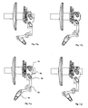
fishing line 28 wound around thespool 26 and a rig (not shown) attached to the free end of theline 28, and with thebail arm 24 in an open position, the user holds the line against spillage with a finger as he prepares to cast the line and then sharply whips the rod and the reel with the free end of the line on the rigging attached thereto forwardly so that the rigging is cast forwards as the line spills off the front end of the spool. Once the rigging has been cast and the rigging has dropped many hundreds of feet below the surface of the water. Thehandle 18 is now rotated and thebail arm 24 is swivelled rearwardly to the position it has inFigure 1 , to wind the line back on to thespool 26. This is effected by couplings within the housing 16 (not shown inFigure 1 ) which simultaneously cause rotation of thebail arm 22 about the axis of thespool 26 and reciprocation of the latter to and fro along its axis. This ensures an even lay of theline 28 on thespool 26. During this phase of operation of the reel, which results in the rigging being lifted towards the surface of the sea very rapidly, the ratio of turns of thebail arm 22 completes seven turns for every single turn of thecrank 20. In the event that a fish bites on the jigging as it is being raised in this fashion, a useroperable lever 30 shown inFigures 2 to 5 is now shifted outwardly into its second position to change the gearing by way of agearing mechanism 32 within thehousing 16. This changes the ratio of turns of thebail arm 22 to each turn of thecrank 20 from 7:1 to 2:1. Thelever 30 is shown in its setting 4 in this phase of operation of the reel. - Details of the manner in which this change of gear is effected is shown more clearly in
Figure 3 . Thus, thecrank 20 is connected to ahandle shaft 34 which extends through thehousing 16 transversely of the spool axis, the end of theshaft 34 that projects outwardly from thehousing 16 on the crank side thereof is surrounded by acompression spring 36 located between thehousing 16 and an inner end of thecrank 20. Thespring 36 is covered by askirt portion 38 extending from the inner end of thecrank 20. -
Figure 3 shows that theshaft 34 comprises a number of parts to facilitate assembly. A portion of theshaft 34 extending from thecrank 20 has an internally screw-threaded hollow which receives an externally screw-threadedshank portion 40 extending from that portion of theshaft 34 which projects from thehousing 16 on the side further from thecrank 20. An outer end of the latter is provided with apivot 42 to which is connected thelever 30 in such a manner that operation of thelever 30 outwardly from thehousing 16 enables theshaft 34 to slide in a direction towards thecrank 20 under the action of thecompression spring 36. Movement of the useroperable lever 30 back to the position it has inFigures 2 and 3 draws theshaft 34 in a direction away from thecrank 20 against the action of thecompression spring 36. A snap action (not shown) holds thelever 30 in this position until the user moves it once again to the outward position. - The
shaft 34 is provided with asleeve 44 which is fixed relative to the portions of theshaft 34 which extend through it and which is provided with a series of splines orexternal teeth 46 extending around a portion of its circumference. In the setting shown inFigure 3 , theseteeth 46, which are external teeth in the sense that they extend around the outside of theshaft 34, engage internal teeth of afirst gear wheel 48 which surrounds theshaft 34 and is generally or substantially orthogonal thereto. Thisgear wheel 48 is fixed to and integral with asleeve portion 50 which is coaxial with and rotatable in relation to theshaft 34. Thesleeve portion 50 in turn is fixed to and integral with acrown wheel 52, the latter having an axis of rotation which is co-linear with the axis of theshaft 34. It is coupled to drive afurther gear 54 coupled to rotate thebail arm 22. Asecond gear wheel 56 also surrounds and is generally or substantially orthogonal to theshaft 34 and is also provided with internal teeth, and external teeth which engage thegearing mechanism 32 coupled to the saidfirst gear wheel 48. Thissecond gear wheel 56 is immediately adjacent and on the crank side of the saidfirst gear wheel 48. As a result, when thelever 30 is moved outwardly from thehousing 16 to enable theshaft 34 to slide longitudinally in a direction towards thecrank 20 under the action of thecompression spring 36, the splines orexternal teeth 46 of theshaft 34 slip out of engagement with the internal teeth of thegear wheel 48 and engage the internal teeth of thegear wheel 56. Under such a change of gear, one portion of thecrank 20 now rotates the crown wheel 52 a higher number of turns than it did in the setting illustrated inFigure 3 , by virtue of thegearing mechanism 32. - The second embodiment is illustrated in
Figures 6 to 12 . - The parts shown in
Figure 6 , and the angle at which they are shown, is especially helpful to an understanding of how these parts cooperate together. So far as the parts shown inFigure 6 is concerned, apart from certain dimensions and apart from a flange (to be referred to) around the shaft (also to be referred to herein), those parts shown inFigure 6 which correspond to parts already illustrated are accorded the same reference numerals as used inFigures 3 to 5 . - It can be seen from
Figure 6 that thegear wheels gear wheel 48 hasinternal teeth 60 and thegear wheel 56 hasinternal teeth 62. Eachtooth wheels Figure 6 . The side of eachtooth 60 which is adjacent to thewheel 56, and the side of eachtooth 62 which is adjacent to thewheel 48, is chamfered or bevelled in planes which are perpendicular to the direction of extension of the tooth. If the flat 64 of the tooth is considered to be the front of the tooth, the face of the chamfering or bevelling is directed rearwardly of the tooth and outwardly of the wheel of which the tooth is a part. The edges of the tooth are generally rounded to reduce the likelihood of wear and friction. The splines orexternal teeth 46 and thesleeve 44 are each provided with a flat 66 directed in a clockwise sense around the axis of thesleeve 44, and consequently also the axes of rotation of thegear wheels Figure 6 . Considering theseflats 66 to be at the front of the splines orexternal teeth 46, therear side 68 of each spline orexternal tooth 46 is generally arcuate and convex. In addition, the edges of the splines orexternal teeth 46 are rounded to reduce wear and friction. - A
flange 70 is integral with and extends around a portion of thesleeve 44 spaced to the right of the splines orexternal teeth 46 as viewed inFigure 6 . When the parts shown inFigure 6 are assembled for operation, thesleeve 44 is slidable in a longitudinal direction relative to its axis so that the splines orexternal teeth 46 may engage theinternal teeth gear wheels flange 70 to shift thesleeve 44 to the left or to the right as viewed inFigure 6 . When a change of gear is made, the various component parts will usually, but not necessarily, be stationary. The change of engagement of the splines orexternal teeth 46 from theinternal teeth 60 of thegear wheel 48, so that thesleeve 44 is to be shifted to the right as inFigure 6 and the splines orexternal teeth 46 are to move into engagement with theinternal teeth 62 of thegear wheel 56, will be considered first. Thesleeve 44 is urged rightwardly to effect this change by a spring mechanism to be described herein. If theteeth 62 happen to be in registration with theteeth 60 at this stage, thesleeve 44 will move fully to the right to enable an immediate change of engagement of theteeth 46 from theteeth 60 of thewheel 48 to theteeth 62 of thewheel 56. - It will be appreciated that because of the
gear mechanism 32, thegear wheel 48 rotates faster than the,gear wheel 56. If, therefore, at the time of switching, theteeth 62 and theteeth 60 are not in registration with one another, theteeth 46 will slide towards theteeth 62 so that they engage the chamfered or bevelled sides of theteeth 62, until full engagement of theteeth 46 with theteeth 62 is possible when theteeth 60 are next in registration with theteeth 62. - Considering a transfer of engagement of the
teeth 46 from theinternal teeth 62 of thewheel 56 to theinternal teeth 60 of thewheel 48, a similar sequence of events will occur bearing in mind now that the wheel into which theteeth 46 are urged is the faster moving of the twowheels teeth sleeve 44 is urged in the left direction as viewed inFigure 6 , the change of gear will be immediate. If, therefore at the time of switching theteeth 62 are positioned in a clockwise sense slightly ahead of theteeth 60, then at the time of switching, theteeth 46 will be unable to engage theinternal teeth 60 fully until the latter have caught up with theteeth 62, whereupon theteeth 46 will be free to slide into full engagement with theteeth 60. - If on the other hand at the time of switching, the
teeth 60 are positioned slightly ahead of theteeth 62 in a clockwise sense, theteeth 46 will slide towards the gap between theteeth 60 until a slanting rear flank of eachtooth 46 abuts the chamfered or bevelled side of anadjacent tooth 60. From here, further rotation of thesleeve 44 by thecrank 20 will cause theteeth 46 to rotate thewheel 56, and consequently through thegear mechanism 32 thewheel 48 at a faster rate so that eachtooth 60 will catch up and overtake theadjacent tooth 62. As this happens, theteeth 46 are first pushed out of the gaps between theteeth 60 by virtue of the chamfered or bevelled sides thereof until theface 64 of eachtooth 60 passes theflat face 66 of theadjacent tooth 46, whereupon the latter is now free to slide in the adjacent gap betweenteeth 60 so that theteeth 46 now fully engage theteeth 60. - A mechanism by which longitudinal sliding of the
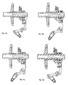
sleeve 44 is effected, is shown more clearly inFigures 7 to 12 . In these Figures, corresponding parts, which have already been labelled with reference numerals in the preceding Figures, have been given the same reference numerals in these Figures. - A
shift member 80 extends above the and below thesleeve 44. It hasinner portions 82 which are sandwiched betweenplates 84 and has a pair ofspigots 86 projecting outwardly from opposite sides of the switchingmember 80. Theplates 84 are connected together by tension springs 88. Theflange 70 of thesleeve 44 is also sandwiched between theplates 84. - A
stirrup 90 is provided with twosides 92 which extend on opposite sides of thesleeve 44. Eachside 92 is provided with a pair ofelongate apertures 94, which slant in relation to a plane perpendicular to the axis of thesleeve 44. Thespigots 84 extend into the slantingapertures 94. A useroperable lever 96 is pivotally attached to the underside of thehousing 16 inFigure 1 so as to be pivotable to the left or to the right viewing the reel along the direction of the axis of thespool 26, or in the direction of view ofFigures 11 and12 for example. Amechanical link 98 couples thelever 96 to thestirrup 90 such that viewing the parts as shown inFigure 11 for example a pivoting movement of thelever 96 from the left to the right lowers thestirrup 90, thus moving it transversely of the axis of thesleeve 44, and slides the switchingmember 80 to the left, and thus longitudinally in relation to the axis of thesleeve 44, whereas movement of the lever to the left moves these various parts in the respective opposite directions. The movement of the switchingmember 80 for example from its left-hand position as viewed inFigure 11 to its right-hand position as viewed inFigure 11 is the step represented by the change fromFigure 11 a toFigure 11 b. Theflange 70 and with it thesleeve 44 remain at this stage in the left-hand position, but are nonetheless urged by the tension springs 88 acting on the left-hand plate 84 which in turn presses theflange 70 to urge the latter and with it thesleeve 44 towards the right-hand position. As and when theteeth 46 are able to slide from engagement with theteeth 60 of thegear wheel 48 into engagement with theteeth 62 of thegear wheel 56, the left-hand plate 84 now moves to the right under the action of the tension springs 88, and with it theflange 70 and thesleeve 44. This is the change illustrated inFigure 11 c relative toFigure 11 b. - Moving the
lever 96 back to its left-hand position will now move the switchingmember 82 and with it the left-hand plate 84 leftwards, being the change illustrated in going fromFigure 11 c toFigure 11 d. Once theteeth 46 are free to disengage theteeth 62 of thewheel 56 and to engage theteeth 60 of thewheel 48, the action of the springs 88 on the right-hand plate 84 shifts that plate, and with it theflange 70 and thesleeve 44 leftwards. This transition is represented inFigure 11 by going fromFigure 11 d back toFigure 11 a. - Whilst the
sleeve 44 has a wider cross-section at one end than at the other inFigures 6 to 12 , it is preferable for that sleeve to be formed so that it has hollows at least at both its ends of the same internal cross-section. These cross-sections are both non-circular. Rotatable spigots (not shown) having the same external cross-section as the internal cross-section of these hollows extend respectively from thecrank 20 and a securing portion on the opposite side of thehousing 16. These spigots do not extend the whole way into the hollow, to ensure that thesleeve 44 is free to be moved to the left or to the right whilst the spigots (not shown) inserted into thesleeve 44 remain fixed in the longitudinal direction of the axis of thesleeve 44. Furthermore, because of the symmetry of such asleeve 44, thecrank 20 and the securing portion (not shown) can be swapped to change the reel from a left-hand reel to a right-hand reel or vice versa. - Numerous variations and modifications to the illustrated reel may occur to the reader. To give one example only, instead of a
lever 96, the more direct link to thestirrup 90 could be effected by way of a push button on the underside of thehousing 16 of thereel 10 to effect up and down movement of thestirrup 90. The gear ratios may be different from the ones given herein. - In the modified drive shown in
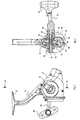
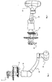
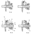
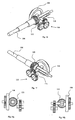
Figures 13 to 18 , atranverse axle 100 can be connected by releasable connection devices (not shown) to thehandle 18 selectively at either one of its two ends, to provide a right- or left-handed reel. - Two
gear wheels axle 100 so as to be in respective spaced apart fixed positions on theaxle 100, but also so as to be rotatable relative thereto and also therewith. - A
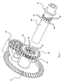
spool shaft 106 to which thespool 26 is attached extends at right angles to theaxle 100, longitudinally of the reel. The twogear wheels spool shaft 106. Thegear wheel 102 meshes directly with an oscillatory motionmechanism drive wheel 108. Thegear wheel 104 is coupled to drive thewheel 108 via agear train 110, theend gear wheel 112 of which is rotationally fixed to and is coaxial with thewheel 108. Thewheels transverse shaft 114 which extends through aslot 116 which is in and extends longitudinally along thespool shaft 106. - A
block 118 at the end of thespool shaft 106 which is further from thespool 26 is formed with an S-slot 119 which receives aspigot 121 on the side of an oscillatorymotion effecting wheel 120 coupled to be driven by thewheel 108. - The
wheel 108 is also coupled to drive abevelled gear 122 itself coupled to rotate thebail arm 22 whilst thespool 26 is being moved forwards and backwards by the oscillating mechanism. - Rotationally fixed on but slideable along the
axle 100 is ahollow shaft 124 at opposite ends of which are respective dog gears 126 and 128. The length of theshaft 124 is such that when thedog gear 126 is coupled to thegear wheel 102, the dog gear is uncoupled from thegear wheel 104, and vice versa. Aslideable bracket 130 below theshaft 124 can be moved transversely by the user by means of alever 132 linked to thebracket 130. Ahelical compression spring 133 is located relative to the bracket in such a fashion that when thelever 132 is operated, theshaft 124 is urged in a direction to change gear, but the gear is only actually changed when the relevant dog gear meshes with a part of the relevant one of the said twogears - It will be appreciated that switching the
lever 132 thereby changes the gearing between spool oscillation speed and bail arm speed on the one hand and the speed with which thehandle 18 is rotated on the other hand. Desirably the two ratios either one of which can be selected are 6.5:1 and 2:1. - Numerous variations and modifications to the illustrated reel may occur to the reader without taking the resulting construction outside the scope of the present invention. To give one example only, the gear ratios could be changed.
Claims (4)
- A fixed spool fishing reel having a handle shaft connected to a handle to be rotated thereby and coupled to a bail arm drive of the reel so that rotation of the handle shaft causes rotation of the bail arm, in which the handle shaft is coupled to the bail arm drive via a gear mechanism that enables the gear ratio between rotation of the handle shaft and rotation of the bail arm drive to be selectively altered, in which the handle is readily releaseably connected to either selected one of the two ends of the handle shaft, characterised in that the handle shaft extends through a hollow dog gear shaft which is rotationally fixed on but slidable along the handle shaft, which dog gear shaft is provided with dog gears at both of its ends, couplable respectively to two gear wheels of the said gear mechanism, the length of the dog gear shaft being such that when one of its ends is coupled to its associated gear wheel the other is not, and correspondingly when the other of its ends is coupled to its associated gear wheel the said one of its ends is not.
- A fixed spool fishing reel according to claim 1, characterised in that the said two gear wheels are respectively on opposite sides of a spool shaft of the reel, coupling between each of the said two gear wheels and a spool shaft oscillatory mechanism of the reel being via respective gearing arrangements to impart different respective ratios of handle rotary speed to oscillatory speed of the spool shaft.
- A fixed spool fishing reel according to claim 2, characterised in that the spool shaft has a slot in it, and the coupling between one of the said two gear wheels and the oscillatory mechanism is by way of a shaft which passes through the said slot.
- A fixed spool fishing reel according to any preceding the claim, characterised in that the hollow dog gear shaft may be moved towards and away from both of the said two gear wheels by way of a lever coupled to the dog gear shaft via a resilient member whereby each dog gear will be urged into engagement with the associated one of the said two gear wheels, and will so engage once they have an appropriate relative angular position.
Priority Applications (1)
| Application Number | Priority Date | Filing Date | Title |
|---|---|---|---|
| EP11007758A EP2433493B1 (en) | 2009-04-03 | 2010-04-01 | A fixed spool fishing reel |
Applications Claiming Priority (2)
| Application Number | Priority Date | Filing Date | Title |
|---|---|---|---|
| GBGB0905869.4A GB0905869D0 (en) | 2009-04-03 | 2009-04-03 | A fixed spool fishing reel |
| PCT/GB2010/000663 WO2010112871A2 (en) | 2009-04-03 | 2010-04-01 | A fixed spool fishing reel |
Related Child Applications (1)
| Application Number | Title | Priority Date | Filing Date |
|---|---|---|---|
| EP11007758.3 Division-Into | 2011-11-04 |
Publications (2)
| Publication Number | Publication Date |
|---|---|
| EP2413690A2 EP2413690A2 (en) | 2012-02-08 |
| EP2413690B1 true EP2413690B1 (en) | 2013-06-19 |
Family
ID=40750114
Family Applications (2)
| Application Number | Title | Priority Date | Filing Date |
|---|---|---|---|
| EP10719599.2A Not-in-force EP2413690B1 (en) | 2009-04-03 | 2010-04-01 | A fixed spool fishing reel |
| EP11007758A Not-in-force EP2433493B1 (en) | 2009-04-03 | 2010-04-01 | A fixed spool fishing reel |
Family Applications After (1)
| Application Number | Title | Priority Date | Filing Date |
|---|---|---|---|
| EP11007758A Not-in-force EP2433493B1 (en) | 2009-04-03 | 2010-04-01 | A fixed spool fishing reel |
Country Status (6)
| Country | Link |
|---|---|
| US (1) | US8960583B2 (en) |
| EP (2) | EP2413690B1 (en) |
| JP (1) | JP5593376B2 (en) |
| AU (1) | AU2010231159A1 (en) |
| GB (1) | GB0905869D0 (en) |
| WO (1) | WO2010112871A2 (en) |
Cited By (1)
| Publication number | Priority date | Publication date | Assignee | Title |
|---|---|---|---|---|
| CN104930136A (en) * | 2015-05-31 | 2015-09-23 | 曹建峰 | Gear control gearbox |
Families Citing this family (7)
| Publication number | Priority date | Publication date | Assignee | Title |
|---|---|---|---|---|
| GB201116267D0 (en) * | 2011-09-20 | 2011-11-02 | Fox Int Group Ltd | A fixed spool fishing reel |
| CN105518248B (en) | 2013-07-05 | 2019-09-24 | 布鲁斯·A.·通盖特 | For cultivating the device and method of downhole surface |
| CN104145894A (en) * | 2014-07-29 | 2014-11-19 | 徐帮奇 | Eccentric variable speed wire reel in same direction |
| US10004214B2 (en) * | 2014-10-17 | 2018-06-26 | Haibao Fishing Tackle Co., Ltd. | Spinning reel with variable gear ratio transmission |
| CN104322469A (en) * | 2014-10-17 | 2015-02-04 | 宁波海宝渔具有限公司 | Variable-speed spinning wheel type line reel for fishing |
| KR101754410B1 (en) | 2015-06-19 | 2017-07-05 | 류상훈 | Reel for fishing |
| WO2020257651A1 (en) * | 2019-06-21 | 2020-12-24 | Biz Outdoors, Inc. | Left handed fishing reel |
Family Cites Families (21)
| Publication number | Priority date | Publication date | Assignee | Title |
|---|---|---|---|---|
| CH268095A (en) * | 1948-04-24 | 1950-05-15 | Vollmar Niklaus | Fishing long cast reel. |
| FR1074776A (en) * | 1952-01-19 | 1954-10-08 | Federnfabrik & Appbau A G | Spinning Rod Reel |
| DE921060C (en) * | 1952-10-10 | 1954-12-06 | Bonner Kunststoff G M B H | Stationary fishing reel with optional drive for spool housing and spool |
| DE918476C (en) * | 1952-10-18 | 1954-09-27 | Sportex G M B H | Fishing winch with multi-speed gear |
| US2807965A (en) * | 1954-04-12 | 1957-10-01 | Frank & Pignard Ets | Variable speed transmission |
| GB925964A (en) * | 1960-09-30 | 1963-05-15 | Urfabriken Ab | Improved automatically variable drive gear for fishing reels |
| US3250489A (en) * | 1963-01-21 | 1966-05-10 | Olympic Fishing Tackle Co | Fishing reel with selectively operable speed selecting means |
| US3600964A (en) * | 1970-03-05 | 1971-08-24 | Shakespheare Of Arkansas Inc | Optionally automatic two speed drive for a fishing reel |
| US3675502A (en) * | 1971-03-08 | 1972-07-11 | Shakespeare Co | Selectively manual or automatic shift control for a two speed drive in a fishing reel |
| US4077587A (en) * | 1976-12-22 | 1978-03-07 | Yoshiya Nishizaki | Spin casting reel |
| JPS56101765U (en) * | 1979-12-31 | 1981-08-10 | ||
| JPH0618459Y2 (en) * | 1986-07-21 | 1994-05-18 | リョービ株式会社 | Spinning reel |
| JPS6359830A (en) * | 1986-08-29 | 1988-03-15 | 株式会社上州屋 | Spinning reel |
| JPH0445507Y2 (en) * | 1987-04-30 | 1992-10-26 | ||
| JP2516625Y2 (en) * | 1989-06-23 | 1996-11-06 | マミヤ・オーピー株式会社 | Double bearing reel |
| JP3290072B2 (en) * | 1996-04-04 | 2002-06-10 | ダイワ精工株式会社 | Fishing reel transmission |
| AUPO406296A0 (en) * | 1996-12-06 | 1997-01-09 | Hsing, Suo | A spinning reel for fishing |
| JP4094821B2 (en) * | 2001-03-19 | 2008-06-04 | ダイワ精工株式会社 | Fishing spinning reel |
| US6672526B1 (en) * | 2002-07-08 | 2004-01-06 | Tiburon Engineering, Inc. | Automatic two-speed transmission for a fishing reel |
| JP4024702B2 (en) * | 2003-03-12 | 2007-12-19 | ダイワ精工株式会社 | Fishing reel |
| GB0608383D0 (en) * | 2006-04-27 | 2006-06-07 | Fox Int Group Ltd | A fixed spool fishing reel |
-
2009
- 2009-04-03 GB GBGB0905869.4A patent/GB0905869D0/en not_active Ceased
-
2010
- 2010-04-01 WO PCT/GB2010/000663 patent/WO2010112871A2/en active Application Filing
- 2010-04-01 JP JP2012502776A patent/JP5593376B2/en not_active Expired - Fee Related
- 2010-04-01 US US13/254,686 patent/US8960583B2/en not_active Expired - Fee Related
- 2010-04-01 AU AU2010231159A patent/AU2010231159A1/en not_active Abandoned
- 2010-04-01 EP EP10719599.2A patent/EP2413690B1/en not_active Not-in-force
- 2010-04-01 EP EP11007758A patent/EP2433493B1/en not_active Not-in-force
Cited By (1)
| Publication number | Priority date | Publication date | Assignee | Title |
|---|---|---|---|---|
| CN104930136A (en) * | 2015-05-31 | 2015-09-23 | 曹建峰 | Gear control gearbox |
Also Published As
| Publication number | Publication date |
|---|---|
| AU2010231159A1 (en) | 2011-10-13 |
| WO2010112871A3 (en) | 2011-05-19 |
| WO2010112871A2 (en) | 2010-10-07 |
| JP2012522499A (en) | 2012-09-27 |
| EP2413690A2 (en) | 2012-02-08 |
| JP5593376B2 (en) | 2014-09-24 |
| EP2433493A1 (en) | 2012-03-28 |
| US8960583B2 (en) | 2015-02-24 |
| GB0905869D0 (en) | 2009-05-20 |
| EP2433493B1 (en) | 2013-03-20 |
| US20120266705A1 (en) | 2012-10-25 |
Similar Documents
| Publication | Publication Date | Title |
|---|---|---|
| EP2413690B1 (en) | A fixed spool fishing reel | |
| KR101676855B1 (en) | Traverse camshaft for fishing reel and reciprocal movement mechanism for fishing reel employing the traverse camshaft | |
| AU759992B2 (en) | Double bearing reel | |
| CN104663604B (en) | Fishing line reel | |
| JP2012522499A5 (en) | ||
| US20040144877A1 (en) | Level wind mechanism for a dual bearing reel | |
| US5201477A (en) | Spinning reel with drag brake mechanism and clutch | |
| TWI682714B (en) | Double bearing reel | |
| US5058447A (en) | Change-speed construction for fishing reel | |
| JP2001505056A (en) | Spinning reel for fishing | |
| US5318243A (en) | Spinning reel having a device for preventing backward rotation of a rotor | |
| EP1849357B1 (en) | A fixed spool fishing reel | |
| JP2503245Y2 (en) | Clutch device for fishing reel | |
| EP2572575B1 (en) | A fixed spool fishing reel | |
| US8905345B2 (en) | Fixed spool fishing reel | |
| JP2000350537A (en) | Clutch operation device for double bearing type reel | |
| EP2111754B1 (en) | Fishing spinning reel | |
| WO2021077004A1 (en) | Baitcaster with line guide mechanism | |
| EP2236027B1 (en) | A fixed spool fishing reel | |
| CN216674367U (en) | Manual shifting fishing line reel | |
| CN216415714U (en) | Swinging winding displacement fishing line reel | |
| JP3490892B2 (en) | Dual bearing reel clutch operating mechanism | |
| JP2570781Y2 (en) | Spinning reel | |
| CN2061760U (en) | Reel for angling | |
| CN116267829A (en) | Manual gear shifting fishing reel |
Legal Events
| Date | Code | Title | Description |
|---|---|---|---|
| PUAI | Public reference made under article 153(3) epc to a published international application that has entered the european phase |
Free format text: ORIGINAL CODE: 0009012 |
|
| 17P | Request for examination filed |
Effective date: 20111121 |
|
| AK | Designated contracting states |
Kind code of ref document: A2 Designated state(s): AT BE BG CH CY CZ DE DK EE ES FI FR GB GR HR HU IE IS IT LI LT LU LV MC MK MT NL NO PL PT RO SE SI SK SM TR |
|
| DAX | Request for extension of the european patent (deleted) | ||
| GRAP | Despatch of communication of intention to grant a patent |
Free format text: ORIGINAL CODE: EPIDOSNIGR1 |
|
| RAP1 | Party data changed (applicant data changed or rights of an application transferred) |
Owner name: FOX INTERNATIONAL GROUP LIMITED |
|
| RIN1 | Information on inventor provided before grant (corrected) |
Inventor name: TAYLOR, ADAM Inventor name: LITTLE, ANDY |
|
| GRAS | Grant fee paid |
Free format text: ORIGINAL CODE: EPIDOSNIGR3 |
|
| GRAA | (expected) grant |
Free format text: ORIGINAL CODE: 0009210 |
|
| AK | Designated contracting states |
Kind code of ref document: B1 Designated state(s): AT BE BG CH CY CZ DE DK EE ES FI FR GB GR HR HU IE IS IT LI LT LU LV MC MK MT NL NO PL PT RO SE SI SK SM TR |
|
| REG | Reference to a national code |
Ref country code: GB Ref legal event code: FG4D |
|
| REG | Reference to a national code |
Ref country code: CH Ref legal event code: EP |
|
| REG | Reference to a national code |
Ref country code: AT Ref legal event code: REF Ref document number: 617130 Country of ref document: AT Kind code of ref document: T Effective date: 20130715 |
|
| REG | Reference to a national code |
Ref country code: IE Ref legal event code: FG4D |
|
| REG | Reference to a national code |
Ref country code: DE Ref legal event code: R096 Ref document number: 602010007950 Country of ref document: DE Effective date: 20130814 |
|
| REG | Reference to a national code |
Ref country code: NL Ref legal event code: T3 |
|
| REG | Reference to a national code |
Ref country code: SE Ref legal event code: TRGR |
|
| REG | Reference to a national code |
Ref country code: NO Ref legal event code: T2 Effective date: 20130619 |
|
| PG25 | Lapsed in a contracting state [announced via postgrant information from national office to epo] |
Ref country code: FI Free format text: LAPSE BECAUSE OF FAILURE TO SUBMIT A TRANSLATION OF THE DESCRIPTION OR TO PAY THE FEE WITHIN THE PRESCRIBED TIME-LIMIT Effective date: 20130619 Ref country code: GR Free format text: LAPSE BECAUSE OF FAILURE TO SUBMIT A TRANSLATION OF THE DESCRIPTION OR TO PAY THE FEE WITHIN THE PRESCRIBED TIME-LIMIT Effective date: 20130920 Ref country code: ES Free format text: LAPSE BECAUSE OF FAILURE TO SUBMIT A TRANSLATION OF THE DESCRIPTION OR TO PAY THE FEE WITHIN THE PRESCRIBED TIME-LIMIT Effective date: 20130930 Ref country code: SI Free format text: LAPSE BECAUSE OF FAILURE TO SUBMIT A TRANSLATION OF THE DESCRIPTION OR TO PAY THE FEE WITHIN THE PRESCRIBED TIME-LIMIT Effective date: 20130619 Ref country code: LT Free format text: LAPSE BECAUSE OF FAILURE TO SUBMIT A TRANSLATION OF THE DESCRIPTION OR TO PAY THE FEE WITHIN THE PRESCRIBED TIME-LIMIT Effective date: 20130619 |
|
| REG | Reference to a national code |
Ref country code: LT Ref legal event code: MG4D |
|
| PG25 | Lapsed in a contracting state [announced via postgrant information from national office to epo] |
Ref country code: HR Free format text: LAPSE BECAUSE OF FAILURE TO SUBMIT A TRANSLATION OF THE DESCRIPTION OR TO PAY THE FEE WITHIN THE PRESCRIBED TIME-LIMIT Effective date: 20130619 Ref country code: BG Free format text: LAPSE BECAUSE OF FAILURE TO SUBMIT A TRANSLATION OF THE DESCRIPTION OR TO PAY THE FEE WITHIN THE PRESCRIBED TIME-LIMIT Effective date: 20130919 |
|
| PG25 | Lapsed in a contracting state [announced via postgrant information from national office to epo] |
Ref country code: LV Free format text: LAPSE BECAUSE OF FAILURE TO SUBMIT A TRANSLATION OF THE DESCRIPTION OR TO PAY THE FEE WITHIN THE PRESCRIBED TIME-LIMIT Effective date: 20130619 |
|
| PG25 | Lapsed in a contracting state [announced via postgrant information from national office to epo] |
Ref country code: CY Free format text: LAPSE BECAUSE OF FAILURE TO SUBMIT A TRANSLATION OF THE DESCRIPTION OR TO PAY THE FEE WITHIN THE PRESCRIBED TIME-LIMIT Effective date: 20130807 Ref country code: PT Free format text: LAPSE BECAUSE OF FAILURE TO SUBMIT A TRANSLATION OF THE DESCRIPTION OR TO PAY THE FEE WITHIN THE PRESCRIBED TIME-LIMIT Effective date: 20131021 Ref country code: IS Free format text: LAPSE BECAUSE OF FAILURE TO SUBMIT A TRANSLATION OF THE DESCRIPTION OR TO PAY THE FEE WITHIN THE PRESCRIBED TIME-LIMIT Effective date: 20131019 Ref country code: EE Free format text: LAPSE BECAUSE OF FAILURE TO SUBMIT A TRANSLATION OF THE DESCRIPTION OR TO PAY THE FEE WITHIN THE PRESCRIBED TIME-LIMIT Effective date: 20130619 Ref country code: SK Free format text: LAPSE BECAUSE OF FAILURE TO SUBMIT A TRANSLATION OF THE DESCRIPTION OR TO PAY THE FEE WITHIN THE PRESCRIBED TIME-LIMIT Effective date: 20130619 Ref country code: CZ Free format text: LAPSE BECAUSE OF FAILURE TO SUBMIT A TRANSLATION OF THE DESCRIPTION OR TO PAY THE FEE WITHIN THE PRESCRIBED TIME-LIMIT Effective date: 20130619 |
|
| PG25 | Lapsed in a contracting state [announced via postgrant information from national office to epo] |
Ref country code: PL Free format text: LAPSE BECAUSE OF FAILURE TO SUBMIT A TRANSLATION OF THE DESCRIPTION OR TO PAY THE FEE WITHIN THE PRESCRIBED TIME-LIMIT Effective date: 20130619 Ref country code: RO Free format text: LAPSE BECAUSE OF FAILURE TO SUBMIT A TRANSLATION OF THE DESCRIPTION OR TO PAY THE FEE WITHIN THE PRESCRIBED TIME-LIMIT Effective date: 20130619 |
|
| PG25 | Lapsed in a contracting state [announced via postgrant information from national office to epo] |
Ref country code: CY Free format text: LAPSE BECAUSE OF FAILURE TO SUBMIT A TRANSLATION OF THE DESCRIPTION OR TO PAY THE FEE WITHIN THE PRESCRIBED TIME-LIMIT Effective date: 20130619 |
|
| PLBE | No opposition filed within time limit |
Free format text: ORIGINAL CODE: 0009261 |
|
| STAA | Information on the status of an ep patent application or granted ep patent |
Free format text: STATUS: NO OPPOSITION FILED WITHIN TIME LIMIT |
|
| PG25 | Lapsed in a contracting state [announced via postgrant information from national office to epo] |
Ref country code: DK Free format text: LAPSE BECAUSE OF FAILURE TO SUBMIT A TRANSLATION OF THE DESCRIPTION OR TO PAY THE FEE WITHIN THE PRESCRIBED TIME-LIMIT Effective date: 20130619 |
|
| 26N | No opposition filed |
Effective date: 20140320 |
|
| REG | Reference to a national code |
Ref country code: DE Ref legal event code: R097 Ref document number: 602010007950 Country of ref document: DE Effective date: 20140320 |
|
| PG25 | Lapsed in a contracting state [announced via postgrant information from national office to epo] |
Ref country code: LU Free format text: LAPSE BECAUSE OF FAILURE TO SUBMIT A TRANSLATION OF THE DESCRIPTION OR TO PAY THE FEE WITHIN THE PRESCRIBED TIME-LIMIT Effective date: 20140401 Ref country code: MC Free format text: LAPSE BECAUSE OF FAILURE TO SUBMIT A TRANSLATION OF THE DESCRIPTION OR TO PAY THE FEE WITHIN THE PRESCRIBED TIME-LIMIT Effective date: 20130619 |
|
| REG | Reference to a national code |
Ref country code: CH Ref legal event code: PL |
|
| REG | Reference to a national code |
Ref country code: IE Ref legal event code: MM4A |
|
| PG25 | Lapsed in a contracting state [announced via postgrant information from national office to epo] |
Ref country code: CH Free format text: LAPSE BECAUSE OF NON-PAYMENT OF DUE FEES Effective date: 20140430 Ref country code: LI Free format text: LAPSE BECAUSE OF NON-PAYMENT OF DUE FEES Effective date: 20140430 |
|
| REG | Reference to a national code |
Ref country code: FR Ref legal event code: PLFP Year of fee payment: 6 |
|
| PG25 | Lapsed in a contracting state [announced via postgrant information from national office to epo] |
Ref country code: IE Free format text: LAPSE BECAUSE OF NON-PAYMENT OF DUE FEES Effective date: 20140401 |
|
| PG25 | Lapsed in a contracting state [announced via postgrant information from national office to epo] |
Ref country code: MT Free format text: LAPSE BECAUSE OF FAILURE TO SUBMIT A TRANSLATION OF THE DESCRIPTION OR TO PAY THE FEE WITHIN THE PRESCRIBED TIME-LIMIT Effective date: 20130619 |
|
| REG | Reference to a national code |
Ref country code: FR Ref legal event code: PLFP Year of fee payment: 7 |
|
| PG25 | Lapsed in a contracting state [announced via postgrant information from national office to epo] |
Ref country code: SM Free format text: LAPSE BECAUSE OF FAILURE TO SUBMIT A TRANSLATION OF THE DESCRIPTION OR TO PAY THE FEE WITHIN THE PRESCRIBED TIME-LIMIT Effective date: 20130619 |
|
| PG25 | Lapsed in a contracting state [announced via postgrant information from national office to epo] |
Ref country code: TR Free format text: LAPSE BECAUSE OF FAILURE TO SUBMIT A TRANSLATION OF THE DESCRIPTION OR TO PAY THE FEE WITHIN THE PRESCRIBED TIME-LIMIT Effective date: 20130619 Ref country code: HU Free format text: LAPSE BECAUSE OF FAILURE TO SUBMIT A TRANSLATION OF THE DESCRIPTION OR TO PAY THE FEE WITHIN THE PRESCRIBED TIME-LIMIT; INVALID AB INITIO Effective date: 20100401 |
|
| PGFP | Annual fee paid to national office [announced via postgrant information from national office to epo] |
Ref country code: GB Payment date: 20160428 Year of fee payment: 7 |
|
| REG | Reference to a national code |
Ref country code: FR Ref legal event code: PLFP Year of fee payment: 8 |
|
| PGFP | Annual fee paid to national office [announced via postgrant information from national office to epo] |
Ref country code: NL Payment date: 20170425 Year of fee payment: 8 |
|
| PGFP | Annual fee paid to national office [announced via postgrant information from national office to epo] |
Ref country code: NO Payment date: 20170426 Year of fee payment: 8 Ref country code: FR Payment date: 20170428 Year of fee payment: 8 |
|
| PGFP | Annual fee paid to national office [announced via postgrant information from national office to epo] |
Ref country code: SE Payment date: 20170427 Year of fee payment: 8 Ref country code: BE Payment date: 20170427 Year of fee payment: 8 Ref country code: IT Payment date: 20170426 Year of fee payment: 8 Ref country code: AT Payment date: 20170428 Year of fee payment: 8 |
|
| PGFP | Annual fee paid to national office [announced via postgrant information from national office to epo] |
Ref country code: DE Payment date: 20170630 Year of fee payment: 8 |
|
| GBPC | Gb: european patent ceased through non-payment of renewal fee |
Effective date: 20170401 |
|
| PG25 | Lapsed in a contracting state [announced via postgrant information from national office to epo] |
Ref country code: GB Free format text: LAPSE BECAUSE OF NON-PAYMENT OF DUE FEES Effective date: 20170401 |
|
| REG | Reference to a national code |
Ref country code: DE Ref legal event code: R082 Ref document number: 602010007950 Country of ref document: DE Representative=s name: LS-MP VON PUTTKAMER BERNGRUBER LOTH SPUHLER MU, DE Ref country code: DE Ref legal event code: R081 Ref document number: 602010007950 Country of ref document: DE Owner name: FOX INTERNATIONAL GROUP LTD., WARLEY, GB Free format text: FORMER OWNER: FOX INTERNATIONAL GROUP LTD., HAINAULT, ESSEX, GB |
|
| PG25 | Lapsed in a contracting state [announced via postgrant information from national office to epo] |
Ref country code: MK Free format text: LAPSE BECAUSE OF FAILURE TO SUBMIT A TRANSLATION OF THE DESCRIPTION OR TO PAY THE FEE WITHIN THE PRESCRIBED TIME-LIMIT Effective date: 20130619 |
|
| REG | Reference to a national code |
Ref country code: DE Ref legal event code: R119 Ref document number: 602010007950 Country of ref document: DE |
|
| REG | Reference to a national code |
Ref country code: NO Ref legal event code: MMEP |
|
| REG | Reference to a national code |
Ref country code: SE Ref legal event code: EUG |
|
| REG | Reference to a national code |
Ref country code: NL Ref legal event code: MM Effective date: 20180501 |
|
| REG | Reference to a national code |
Ref country code: AT Ref legal event code: MM01 Ref document number: 617130 Country of ref document: AT Kind code of ref document: T Effective date: 20180401 |
|
| REG | Reference to a national code |
Ref country code: BE Ref legal event code: MM Effective date: 20180430 |
|
| PG25 | Lapsed in a contracting state [announced via postgrant information from national office to epo] |
Ref country code: AT Free format text: LAPSE BECAUSE OF NON-PAYMENT OF DUE FEES Effective date: 20180401 Ref country code: NO Free format text: LAPSE BECAUSE OF NON-PAYMENT OF DUE FEES Effective date: 20180430 Ref country code: DE Free format text: LAPSE BECAUSE OF NON-PAYMENT OF DUE FEES Effective date: 20181101 Ref country code: NL Free format text: LAPSE BECAUSE OF NON-PAYMENT OF DUE FEES Effective date: 20180501 Ref country code: SE Free format text: LAPSE BECAUSE OF NON-PAYMENT OF DUE FEES Effective date: 20180402 |
|
| PG25 | Lapsed in a contracting state [announced via postgrant information from national office to epo] |
Ref country code: BE Free format text: LAPSE BECAUSE OF NON-PAYMENT OF DUE FEES Effective date: 20180430 |
|
| PG25 | Lapsed in a contracting state [announced via postgrant information from national office to epo] |
Ref country code: FR Free format text: LAPSE BECAUSE OF NON-PAYMENT OF DUE FEES Effective date: 20180430 Ref country code: IT Free format text: LAPSE BECAUSE OF NON-PAYMENT OF DUE FEES Effective date: 20180401 |