EP2413644A2 - Station de base et système de communication cellulaire sans fil avec commande de puissance de liaison montante - Google Patents
Station de base et système de communication cellulaire sans fil avec commande de puissance de liaison montante Download PDFInfo
- Publication number
- EP2413644A2 EP2413644A2 EP11173391A EP11173391A EP2413644A2 EP 2413644 A2 EP2413644 A2 EP 2413644A2 EP 11173391 A EP11173391 A EP 11173391A EP 11173391 A EP11173391 A EP 11173391A EP 2413644 A2 EP2413644 A2 EP 2413644A2
- Authority
- EP
- European Patent Office
- Prior art keywords
- base station
- cell
- transmit power
- terminal
- power
- Prior art date
- Legal status (The legal status is an assumption and is not a legal conclusion. Google has not performed a legal analysis and makes no representation as to the accuracy of the status listed.)
- Withdrawn
Links
Images


Classifications
-
- H—ELECTRICITY
- H04—ELECTRIC COMMUNICATION TECHNIQUE
- H04W—WIRELESS COMMUNICATION NETWORKS
- H04W52/00—Power management, e.g. TPC [Transmission Power Control], power saving or power classes
- H04W52/04—TPC
- H04W52/18—TPC being performed according to specific parameters
- H04W52/28—TPC being performed according to specific parameters using user profile, e.g. mobile speed, priority or network state, e.g. standby, idle or non transmission
- H04W52/283—Power depending on the position of the mobile
-
- H—ELECTRICITY
- H04—ELECTRIC COMMUNICATION TECHNIQUE
- H04W—WIRELESS COMMUNICATION NETWORKS
- H04W52/00—Power management, e.g. TPC [Transmission Power Control], power saving or power classes
- H04W52/04—TPC
- H04W52/18—TPC being performed according to specific parameters
- H04W52/24—TPC being performed according to specific parameters using SIR [Signal to Interference Ratio] or other wireless path parameters
- H04W52/242—TPC being performed according to specific parameters using SIR [Signal to Interference Ratio] or other wireless path parameters taking into account path loss
-
- H—ELECTRICITY
- H04—ELECTRIC COMMUNICATION TECHNIQUE
- H04W—WIRELESS COMMUNICATION NETWORKS
- H04W52/00—Power management, e.g. TPC [Transmission Power Control], power saving or power classes
- H04W52/04—TPC
- H04W52/18—TPC being performed according to specific parameters
- H04W52/24—TPC being performed according to specific parameters using SIR [Signal to Interference Ratio] or other wireless path parameters
- H04W52/243—TPC being performed according to specific parameters using SIR [Signal to Interference Ratio] or other wireless path parameters taking into account interferences
- H04W52/244—Interferences in heterogeneous networks, e.g. among macro and femto or pico cells or other sector / system interference [OSI]
-
- H—ELECTRICITY
- H04—ELECTRIC COMMUNICATION TECHNIQUE
- H04W—WIRELESS COMMUNICATION NETWORKS
- H04W52/00—Power management, e.g. TPC [Transmission Power Control], power saving or power classes
- H04W52/04—TPC
- H04W52/06—TPC algorithms
- H04W52/14—Separate analysis of uplink or downlink
- H04W52/146—Uplink power control
-
- H—ELECTRICITY
- H04—ELECTRIC COMMUNICATION TECHNIQUE
- H04W—WIRELESS COMMUNICATION NETWORKS
- H04W52/00—Power management, e.g. TPC [Transmission Power Control], power saving or power classes
- H04W52/04—TPC
- H04W52/18—TPC being performed according to specific parameters
- H04W52/22—TPC being performed according to specific parameters taking into account previous information or commands
- H04W52/225—Calculation of statistics, e.g. average, variance
Definitions
- the present invention relates to a base station and a cellular wireless communication system, and relates in particular to a base station and a cellular wireless communication system that makes uplink transmit power control settings while taking the applied interference into account.
- the present invention also relates to power control of terminals by base stations in cellular wireless communication system utilizing the orthogonal frequency division multiple access system (OFDMA).
- OFDMA orthogonal frequency division multiple access system
- Cellular wireless communication systems are comprised of communication areas called cells which are base stations ⁇ sometimes referred to as eNB (e-UTRA Node B) ⁇ that cover a particular communication area.
- eNB e-UTRA Node B
- These base stations have different names such as macrocell base stations (MeNB), picocell base stations, and femtocell base stations (HeNB: Home eNB), according to the width, and function of their area.
- the cellular wireless base station having the largest area is called the macrocell base station which contains terminals (sometimes referred to as UE or User Equipment) within a range from a few hundred to a few thousand meters.
- the interference power generated from the neighboring cell base station in the downlink and the interference power from the terminals belonging to the neighboring cell base station in the uplink are known to exert effects on the quality of the communication link.
- the desired signal from that base station's own cell must compete with interference power generated from adjacent cells.
- This interference power causes the SINR (Signal to Interference and Noise Power Ratio) which is an index for expressing received power quality to deteriorate and appears as a drastic drop in communication speed. Lowering the interference from adjacent cells is therefore an essential element in improving the overall system in terms of channel capacity during wireless access.
- Transmit power control at the terminal during the uplink operation during wireless access is also closely involved with interference control. This relation is described using FIG. 13 .
- the terminal 13-A in the figure must transmit at high power to overcome the path loss generated between itself and the serving cell base station 11-A (base station to which terminal 13-A belongs) and attain the desired signal (solid line arrows in the figure) at the specified communication quality.
- the high power at which the terminal 13-A transmits arrives at the neighboring cell base station 11-B (broken line arrows in the figure) as interference power which is a large interference power at the terminal 13-B that is connected to the neighboring cell base station 11-B.
- the power from the transmission by the terminal 13-B arrives at the base station 11-A as interference power in the same way and acts as interference power on the terminal 13-A connected to the base station 11-A.
- the 3rd Generation Partnership Project or 3GPP which is the Standards Development Organization (SDO) is working to establish standards for OFDMA type wireless communication systems called LTE (Long Term Evolution).
- LTE Long Term Evolution
- the transmit power control for the LTE uplink shared (PUSCH: Physical Uplink Shared Channel) is expressed by the following formula as defined in 3GPP TS36.213, "Physical layer: procedures", v9.1.0, Mar. 2010 .
- P PUSCH i min P MAX , 10 ⁇ log 10 M PUSCH i + P 0 _PUSCH + ⁇ ⁇ PL + ⁇ TF i + f i
- the base station 11 notifies all the terminals 13 belonging to its own cell of control parameters except for PL (Pathloss).
- the terminal 13 decides the transmit power utilizing the measured PL and the notified parameter.
- PL Physical layer: procedures
- Each parameter is described later on (See 3GPP TS36.213, "Physical layer: procedures", v9.1.0, Mar. 2010 for more detailed information.)
- FIG. 14 shows a concept view of the control scheme.
- the vertical axis is the transmit power.
- the horizontal axis is the PL between the base station 11 and the terminal 13.
- the communication quality deteriorates as the PL becomes larger so the terminal 13 must increase the transmit power in order to compensate for the PL.
- the ⁇ or alpha in the formula is a predetermined coefficient for compensating the PL.
- the ⁇ falls below 1.0 the PL is not fully compensated, and the base station does not maintain the received power at an equal amount among the terminals.
- the ⁇ equals 0 then the path loss is no longer compensated so transmit power control that is largely dependent on the base power P 0_PUSCH is implemented.
- This scheme is sometimes called the fractional power control equation.
- the terminal transmit power at the cell-center is set by adjusting the ⁇ after determining the transmit power for maintaining communication quality at the cell-edge.
- the technology in Japanese Unexamined Patent Application Publication (Translation of PCT Application) No. 2010-516184 for example discusses a method for setting the uplink target received power quality so as to allow communications within the cell itself, and then raising the uplink target received power quality of the cell-center terminal.
- This power control method takes the applied interference into account however the terminal itself regulates the transmit power by correcting the target SINR.
- this method does not always take into account the extent of interference that adjacent cells apply to each other when this method cannot be applied to all terminals.
- the base station should preferably provide fixed rules to terminals under its control as broadcast information from the base station.
- Terminal transmit power control to compensate for the path loss in the femtocell during uplink communication from the terminal to the femtocell base station, achieves high communication throughput at the terminals within the femtocell base station but also increases the applied interference at terminals within the macrocell base station.
- the present invention has the objective of providing a base station for wireless communication systems that controls the transmit power in terminals while both reducing the interference applied to neighboring cells and attaining high communication quality in its own cell during the uplink.
- the present invention controls parameters for uplink transmit power control according to the distribution of terminals within the cell of the femtocell base station.
- the femtocell base station collects the terminal distribution within the cell, and selects terminals to represent the cell-center and cell-edge from the terminals within the cell.
- the femtocell base station further calculates the maximum allowed transmit power of the macrocell for the respective cell-center and the cell-edge terminals within the macrocell.
- the femtocell base station sets a respective transmit power for the cell-center and the cell-edge that does not exceed the range of the maximum transmit power, adjusts the transmit power control parameters to allow limiting the terminal to the power value that was set, and notifies the terminal.
- a first aspect of the present invention to resolve the above problems provides a base station for a cellular wireless communication system comprised of a plurality of base stations and terminals for controlling the transmit power based on specified transmit power control parameters and the path loss with the base station carrying out communication; in which the base station:
- a second aspect of the present invention to resolve the above problems provides a cellular wireless transmission system comprising a first base station for communicating with a plurality of terminals, and a second base station adjacent to the applicable first base station, and the cellular wireless communication system controls the transmit power based on the specified transmit power control parameters and path loss in communication between the base station and the terminals; in which the first base station:
- the present invention is capable of providing control of transmit power in terminals while both minimizing the interference applied to neighboring cells and attaining high communication quality in its own cell during the uplink.
- the present invention can for example be effectively applied to femtocell base stations.
- the improved easy installation of femtocell base stations has made hotspot installation simpler in cellular wireless communication systems, which is beneficial in terms of minimizing effects on the macrocell base station.
- a base station considered here as exerting interference can for example be the femtocell base station.
- the femtocell base station in the following embodiment is therefore a conceptual base station that includes the typical femtocell base station category called ultra-small base stations that are connected to an IP network.
- a base station such as macrocell base station may be considered here as a base station affected by applied interference.
- the macrocell base station is considered here as a base station within the scope of a typical macrocell base station the same as for femtocell base stations but is not limited to such base stations.
- FIG. 1 describes the overall configuration of the cellular wireless communication system of the present embodiment.
- the cellular wireless communication system of the present embodiment is comprised for example the macrocell base stations 1201-M and the femtocell base station 1201-H.
- the terminal 1203 can communicate with the macrocell base stations 1201-M and the femtocell base station 1201-H.
- the base station 1201 provides communication among terminals 1203 located at separate positions, and data communication services between terminals and contents providers through a core network 1202 configured from host devices such as element management servers, mobility management elements, and gateways. Even among base stations however, the femtocell base station connects to the core network 1202 via ISP (Internet Service Provider) network.
- ISP Internet Service Provider
- the femtocell base station 1201-H sets the transmit power control parameters according to the initial setups P101 after startup.
- the parameters set in the initial setup P101 may even be pre-installed parameters or may be parameters set by an OAM device.
- the terminal 1203-H connected to the femtocell base station 1201-H receives the downlink reference signal sent by the macrocell base station 1201-M, and measures the downlink signal quality (for example the received power) (P102).
- the downlink signal quality for example the received power
- One macrocell base station is displayed in the drawing however the downlink signals from a plurality of macrocell base stations may be received and respectively measured.
- the femtocell base station 1201-H may then notify the measurement configuration to the terminal 1203-H.
- the terminal 1203-H may report (measurement report) the downlink received power quality measured on the reference signals sent from the femtocell base station 1201-H and from the macrocell base station 1201-M, to the femtocell base station 1201-H functioning as the serving cell.
- the femtocell base station 1201-H calculates statistical information based on the measurement report from the terminals 1203-H, where the measurement report includes the received power information of serving cell and also that of neighboring cells (P103).
- the femtocell base station 1201-H selects the cell-center terminal and the cell-edge terminal (P104) from information in the control table acquired in P103.
- the femtocell base station 1201-H also determines the respective "maximum allowed transmit power" (P105) for the cell-center terminal and the cell-edge terminal that were set in P104.
- the femtocell base station 1201-H calculates the transmit power based on the modulation method scheduled for use in the terminals and the maximum allowed transmit power in the terminal of cell-center terminal. In P107, the femtocell base station 1201-H calculates the transmit power for the cell-edge terminal and the scheduled modulation method for use in the terminals in the same way. In P108, the femtocell base station 1201-H determines the transmit power control parameters for all terminals within the cell, utilizing the cell-edge terminal transmit power and the cell-center terminal power. All terminals are notified of the parameters that were set and the terminals execute open-loop power control. The above process provides high throughput communications that take the applied interference into account. These steps P103 through P108 are described next in detail.
- Step P103 is first of all described next while referring to FIG. 3 .
- the femtocell base station 1201-H and the macrocell base stations 1201-M (#1, #2) are installed in the system.
- the terminals 1203-H connected to the femtocell base stations, measure the downlink reference signal from the macrocell base stations 1201-M (#1, #2).
- the terminals 1203-H respectively report the measurement results to the femtocell base station 1201-H.
- the femtocell base station 1201-H stores the reported measurement results in a received power report table 4011 such as shown in FIG. 4 .
- the received power report table 4011 for example retains each base station ID (identifier) and received power information as a set along with each terminal ID.
- the values stored in the received power report table 4011 may even be instantaneous values or statistical values (e.g. mean values or reported frequency, etc.).
- the femtocell base station 1201-H updates the information in the received power report table 4011 each time a report arrives from the terminals.
- the method for selecting the cell-center terminal and the cell-edge terminal in P104 is described next.
- the method for selecting the cell-center terminal is considered first.
- One method for selecting the cell-center terminal for example is selecting one terminal meeting the condition that the received power from the femtocell base station 1201-H is the same or higher than a preset threshold value for received power from the macrocell base stations 1201-M.
- Another method is setting a received power from the macrocell base stations 1201-M that is a certain threshold value or lower as a judgment criteria and then selecting a terminal that satisfies that judgment criteria.
- the method for selecting the cell-edge terminal may for example select one terminal from satisfying the condition that the received power from the macrocell base stations 1201-M is the same or higher than a preset threshold value for the received power from the femtocell base station 1201-H.
- Another method may for example select one cell-edge terminal from among terminals satisfying the condition that the difference in received power from the femtocell base station 1201-H and the received power from the macrocell base stations 1201-M is the same or lower than a preset threshold value.
- the cell-center and the cell-edge may here be defined in terms of the size of the path loss rather the physical distance from the femtocell.
- the terminal where the received power from the femtocell base station 1201-H is a maximum may be defined as the cell-center terminal, and the terminal where the received power is minimum may be defined as the cell-edge terminal.
- the terminal #3 was selected as the cell-center terminal, and the terminal #2 was selected as the cell-edge terminal.
- FIG. 6 is a diagrammatic representation of FIG. 6 .
- the femtocell base station 1201-H calculates the path loss 503 between the terminals 1203-H and the macrocell base stations 1201-M from the downlink transmit power 501 sent from the macrocell base stations 1201-M, and from the downlink received power 502 from the macrocell base stations 1201-M that was received and measured by the terminals 1203-H.
- the downlink transmit power from the macrocell base station can be acquired as needed as described later on.
- the maximum allowed transmit power 505 sent by the femtocell base station 1201-H can be calculated by obtaining the difference (sum of each absolute value) between the pathloss 503 that was found, and the allowed interference power quantity 504 received by the macrocell base stations 1201-M.
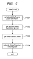
- the femtocell base station 1201-H execute step P105 in the detailed procedure shown in FIG. 6 .
- the femtocell base station 1201-H collects information on the allowed interference power quantity 504.
- This allowed interference power quantity 504 may even be a value found from the receive sensitivity of the macrocell base stations 1201-M. Power that is lower than the receive sensitivity cannot be distinguished from noise and so can be treated as power at a level that can be ignored.
- An interference power quantity 504 allowable at the macrocell base stations 1201-M as part of the system design may also be set as a system parameter.
- the OAM device may set an allowed interference power (or receive sensitivity) in the femtocell base station 1201-H, or may provide an initial setup for the femtocell base station 1201-H.
- the femtocell base station 1201-H estimates the downlink received power 502 from the macrocell base stations 1201-M measured by the terminals 1203-H. To make this estimation, the femtocell base station 1201-H may utilize the value for the received power information report table 4011 that was used to sort the cell-center terminals and the cell-edge terminals.
- the femtocell base station 1201-H collects the downlink transmit power information 501 from the macrocell base stations 1201-M.
- Methods for collection from the backhaul line may include exchange of downlink transmit power information between each of the base stations or instructions sent from the OAM device.
- the femtocell base station 1201-H may receive macrocell base station 1201-M information and control channels if they contain a function for receiving information from terminals. If these channels can be received then macrocell base station transmit power can be directly obtained. Alternatively, the path loss may be reported when the terminals report the received power quality from neighboring cells.
- the femtocell base station 1201-H calculates the maximum allowed transmit power 505.
- the pathloss 503 between the terminals 1203-H and the macrocell base stations 1201-M can be calculated from the difference between the information 501 and 502 collected in P1002 and P1003.
- the maximum allowed transmit power 505 can be calculated if the sum of the absolute values for the pathloss 503 and the allowed interference power quantity 504 can be obtained.
- the interference power is a large limiting condition when calculating the maximum allowed transmit power 505 for both the cell-edge terminal and cell-center terminal. Compared to the cell-center terminal, the cell-edge terminal causes a relatively larger interference power to the macrocell base station 1201-M.
- the cell-edge terminal tends to have a maximum allowed transmit power 505 that is smaller than the cell-center terminal.
- the femtocell base station 1201-H stores the maximum allowed transmit power for the cell-edge terminal and the maximum allowed transmit power for the cell-center terminal as needed.
- Step P106 for calculating the transmit power of the cell-center terminal is described next using FIG. 7 .
- Step P1011 is a process for loading the maximum allowed transmit power of the cell-center terminal that was calculated in P105.
- Step P1012 is a process for setting the target MCS of the cell-center terminal.
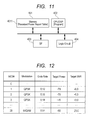
- the MCS as shown in FIG. 12 is the modulation method and code rate set and when the MCS is high (large MCS number) typically the modulation order is large and the code rate also high. In other words setting a high MCS requires attaining a high quality channel so that the required power must also be high.
- the figures shown in FIG. 12 are only examples and do not limit the embodiments. A high value must first of all be selected for the MCS of the cell-center terminal in order to achieve a high throughput for the femtocell base station.
- the femtocell base station sets a power that matches the above MCS.
- the base station sets a transmit power that allows successful communication for example when using a target MCS (modulation and coding scheme) for setting the transmit power (P1013) of the cell-center terminal.
- the transmit power can be calculated from the sum of the path loss between the cell-center terminals and the femtocell base station 1201-H, and the SNR (Signal to Noise Ratio) required for each modulation method, and the noise power in the femtocell base station 1201-H.
- An alternative method when calculating the transmit power using the SINR is to also measure the index IoT (Interference over Thermal Noise) value for the arriving interference power in addition to the noise power as part of the measurement. This implies that the femtocell base stations measure IoT with a certain periodicity.
- the base station decides whether or not the transmit power calculated in P1013 is the same or lower than the maximum allowed transmit power obtained in P1011. If the decision is Yes, then the process proceeds to P1015 and if No the process proceeds to P1016. The decision may set unconditionally to Yes when the target MCS is already the minimum value.
- the transmit power found in P1013 is stored as the cell-center terminal transmit power. The path loss between the cell-center terminal and the femtocell base station 1201-H may also be stored.
- the step P1016 may comprise a loop that lowers the target MCS to return to P1012 and repeats P1012 through P1014.
- the method for setting the transmit power of the cell-edge terminal in P107 is described next using FIG. 8 .
- the step P2011 is the process for loading the maximum allowed transmit power of the cell-edge terminal the same as in P1011.
- the femtocell base station 1201-H set the transmit power of the cell-edge terminal in the maximum allowed transmit power acquired in P2011.
- the femtocell base station 1201-H execute a process for estimating the received power quality at the femtocell base station 1201-H when the cell-edge terminal sent a transmission at the maximum allowed transmit power.
- the uplink quality from the cell-edge terminal is found by subtracting the path loss between the femtocell base station 1201-H and the terminals 1023-H from the maximum allowed transmit power. Since the path loss during the downlink is considered the same as in the uplink, the femtocell base station 1201-H executes a process for calculating the downlink path loss.
- the downlink path loss may be found from the difference between the received power from the femtocell base station 1201-H that received the path loss reported by the cell edge terminal in the received power report table 4011 ( FIG. 4 ) and the transmit power of the femtocell base station 1201-H.
- the downlink path loss may alternatively be found from the MCS of the downlink transmission that was set for the terminal 1203-H.
- the downlink path loss may be found by adding the differential between the femtocell base station 1201-H transmit power and maximum allowed transmit power, to the power requirements of the MCS used in downlink communication.
- the femtocell base station can moreover set the target MCS of the cell-edge terminal, and for example first of all select a high value for the MCS.
- step P2014 a decision is made whether the estimated received power quality satisfies the quality required for successful communications with the target MCS.
- the quality for successful communication with the target MCS can be preset and stored for each target MCS.
- the received quality may for example be set as SNR or as SINR.
- a high target MCS value in an obtainable range may be selected to achieve high throughput. If the estimated received power quality satisfies the above conditions then the process can proceed to P2015. If the received power quality fails to meet the conditions then the process proceeds to P2016.
- the femtocell base station stores the transmit power along with the above target MCS. The path loss between the cell-edge terminal and the femtocell base station 1201-H may also be stored.
- the femtocell base station lowers the target MCS and adjusts the received power quality to a quality required for the target MCS.
- P108 is a step for determining the common parameters for all terminals within the cell from the transmit power of the cell-center terminal, and the transmit power of the cell-edge terminal.
- the transmit power 511 of the cell-center terminal and the transmit power 512 of the edge terminal are subjected to linear interpolation for path loss as shown in FIG. 9 (514) in order to calculate the transmit power 513 of the other terminals.
- a power control parameter e.g., a parameter equivalent to the slope or intercept
- the femtocell base station 1201-H may notify all terminals under its control of this common power control parameter.
- the power control parameter found in the above process is reported to the terminals.
- the parameter notification to all terminals may be sent via a report or notification wireless (radio) channel. If the reported power control parameter has been changed from the previously used parameter then the terminals 1203-H updates the power control parameter and reconfigures the connection.
- Each of the terminals 1203-H belonging to the femtocell base station 1201-H controls the path loss between its own terminal and the femtocell base station 1201-H, and the transmit power based on the reported power control parameter.
- FIG. 10 shows a function block diagram of the femtocell base station of this embodiment.
- a transmitter 411 is a block utilized by the femtocell base station 1201-H for sending downlink signals to the terminals 1203-H. A process for converting the downlink signal from a baseband signal to an RF (radio frequency) signal may also be included here.
- the transmitter 411 also contains a transmit antenna for sending radio waves.
- a receiver 412 is a block for allowing the femtocell base station 1201-H to receive uplink signals from the terminal 1203-H. A process for converting the uplink signal from an RF signal to a baseband signal may also be included here.
- the receiver 412 also contains a receive antenna for receiving radio waves.
- a common antenna that both receives and transmits radio waves may also be used.
- a network I/F (network interface) 413 is a block serving as an interface for coupling the femtocell base station 1201-H to the core network 1202 by way of the backhaul lines.
- the coupling via the core network 1202 provides mobile communication functions including information exchange between base stations, mobility management, communication with OAM devices, data transmission and receiving of data required by the terminals 1203-H and voice calls, etc.
- the L1 processing unit 414 is a unit for allowing the femtocell base station 1201-H to perform signal processing in the physical layers.
- the main processing tasks for transmitting include FFT (Fast Fourier Transform), or adaptive modulation, error correction coding, layer mapping and precoding processing called MIMO (Multiple Input Multiple Output) signal processing.
- Main processing tasks for receiving are demodulation or decoding for removing the modulation or coding processing applied on the transmitting side.
- Data for transmission to the terminals is obtained from the L2/L3 processing unit 415, and data obtained from the terminals is sent to the L2/L3 processing unit 415.
- the L2/L3 processing unit 415 is also a block including radio resource management functions such as cell interference control.
- the statistical information processing unit 416 is a block that performs statistical processing to acquire information needed for executing the processing in this embodiment.
- the received power report table 4011 ( FIG. 4 ) stores the information generated in this block. This received power report table 4011 may also be applied to finding the distribution of terminals 1203-H within the cell and the positional relationships with each base station, and for calculating each type of path loss.
- the TPC parameter determination unit 417 is a block for executing the processing in the sequence for P104 through P108 ( FIG. 2 ) in the embodiment.
- the TPC parameter determination unit 417 operation is linked to the statistical processing unit 416 in order to search information in the received power report table 4011 ( FIG. 4 ) acquired by the statistical information processing unit 416. Allowed power information and power information for calculating the path loss may be acquired through information exchange between base stations or the OAM device by way of the network I/F 413.
- FIG.. 11 is a drawing showing the hardware structure of the femtocell base station 1201-H of the present embodiment.
- the memory unit 401 stores the received power report table 4011 as shown in FIG. 4 .
- the CPU-DSP unit 402 may for example be comprised of a program to execute P103 through P108 as the unique processing of this embodiment.
- the logic circuit 404 is a section that supports program functions executed by the CPU-DSP unit 402.
- the I/F 403 is a collective name for the interface with the wireless antenna and the interface with the backhaul line, etc.
- the method disclosed in this embodiment is capable of adequately lowering the interference applied to the macrocell base station 1201-M to ensure communication quality with the femtocell base station 1201-H by setting the transmit power of the cell-edge terminal within the range of the allowed interference power.
- the method of the embodiment can also provide high speed communication quality to the cell-center terminal. After setting the transmit power for the cell-center terminal and the cell-edge terminal, this method sets the transmit power for other terminals by linear interpolation of both (cell-center and cell-edge) terminals.
- the terminal 1203-H adjusts the maximum target MCS after measuring the downlink receive power from the femtocell base station 1201-H, and the downlink receive power from the macrocell base station 1201-M. Uplink interference will be suppressed only when all terminals posses the processing disclosed in Japanese Unexamined Patent Application Publication (Translation of PCT Application) No. 2010-516184 .
- the femtocell base station 1201-H adjusts the target MCS rather than the terminals, by methods such as in P105, P106.
- the femtocell base station 1201-H can control the uplink interference applied to the other base stations without omissions.
- the base stations collectively set the power control parameters jointly used by all terminals, so that all terminals 1203-H within the cell utilize a commonly applied allowed interference power not unique to each terminal.
- the technique disclosed in the first embodiment is described next as a detailed method assuming usage is applied to LTE.
- the condition in P102 of FIG. 2 required for the terminal 1203-H to perform measurement may be set as a value in the initial setup in P101, and notification made by using an RRC message.
- the measurement scheme utilizes a function for reporting the RSRP (Reference Signal Received Power) or RSRQ (Reference Signal Received Power) or RSRQ (Reference Signal Received Quality) .
- Reporting the RSRQ allows reporting in a format that is a power ratio of the RSSI (Received Signal Strength Indication) including the interference power of the reference signals from the other cells, and the received signal of its own cell.
- the report may be in the form of either the RSRP or the RSRQ, or a collection of both. However, usually one of these formats is used due to the possibility that numerous configuration rewrites will occur, and a training period then set, and other markers (indicators) collected just within that time. The training period may be triggered periodically or manually via OAM devices.
- femtocell base station 1201-H manages the RSRP and RSRQ respectively via the received power report value control table 4011.
- the terminal 1203-H performs normalizing each time a report value is generated, so the femtocell base station 1201-H that received the report may manage just the instantaneous value.
- the femtocell base station 1201-H may also incorporate the reporting frequency (or rate) when using statistics to manage the RSRP and RSRQ. Control can also be achieved according to the terminal distribution by recording the value from the report value in combination with the frequency (rate) over a long period of time.
- the terminal 1203-H is seldom exposed to large changes in the fading environment. On the other hand, if moved from one room to another then the received power distribution is likely to change due to effects from the walls. While stationary within a room, the terminal 1203-H returns a report value containing a fixed receive power to the femtocell base station 1201-H.
- the femtocell base station 1201-H is in other words capable of decided at what position the terminal 1203-H is stationary or stopped from the count obtained from the returned report values.
- the power report value with the largest reporting frequency or rate indicates the position where the terminal 1203-H is most often stopped or stationary, that value may be set as a general indicator of power at the cell-center. Conversely, a power report value whose reporting count (frequency) never reaches a specified count can be judged as a location where the terminal 1203-H is almost never present.
- an evaluation function may prove advisable to reflect the above information when selecting the cell-center terminal and the cell-edge terminal.
- an evaluation function can be generated by utilizing a forgetting average, and then after reducing the forgetting factor, continuously acquiring the average value from the report value spanning a long time period. The calculation can also be made during cell-center and cell-edge terminal selection by excluding report value figures that are lower than a specified value. Even if there are no actual cell-center and cell-edge terminals, one can assume the presence of terminals able to return report value results where a forgetting average was acquired.
- a more accurate power setting can be provided for selecting a cell-center terminal and cell-edge terminal by utilizing a value that takes into account the reporting frequency rather than a value utilizing a simple average of the reported power values.
- the CQI (Channel Quality Indication) Report is another method for reporting the downlink communication quality from the femtocell base station.
- the CQI value may be set as one method for selecting the cell-center terminal and cell-edge terminal.
- Power control parameters such as for expressing linear interpolation formulas also including other terminals may be set in P108 based on the power of the cell-center terminal and cell-edge terminal.
- the power control formula for LTE joint traffic channels for example may be expressed by writing as follows.
- P PUSCH i min P MAX , 10 ⁇ log 10 M PUSCH i + P 0 _ PUSCH + ⁇ ⁇ PL + ⁇ TF i + f i
- the left side of the formula is equivalent to the cell-edge and cell-center terminal power.
- the ⁇ TF and f (i) are adjustment components for use during communication and can therefore be ignored.
- the M PUSCH (I) may be considered a given value of the OFDMA resource, and viewed as a specific value for use during power control.
- This formula can be expressed as a linearly interpolated formula by setting the coefficient ( ⁇ ) by which to multiply the path loss and the reference (base) power (P 0_PUSCH ).
- These ( ⁇ ) and P 0_PUSCH ) values can be calculated by applying the above formula respectively for the cell-edge terminal and cell-center terminal and solving the system of equations.
- the coefficient ( ⁇ ) is a coefficient for compensating for path loss, and is the dominant parameter for all terminals. Control can of course also be achieved based on the same approach for other than joint traffic channel power control.
- the method disclosed in this embodiment is capable of setting the transmit power of the cell-edge terminal to the allowed interference power in LTE systems, and lowering the interference applied to the macrocell base station 1201-M, and ensuring the communication quality to the femtocell base station 1201-H.
- the first embodiment deals with the case in P107 where the maximum allowed transmit power of the cell-edge terminal is small. If the maximum allowed transmit power is small, then the estimated communication quality at the femtocell base station 1201-H will sometimes be worse than expected.
- the problem can be resolved by implementing control linked to the cell-edge terminal scheduling method to lower the power density, or by increasing the allocation resources.
- allocating a large quantity of resources is an easy to employ avoidance method.
- resources can be allocated along the time axis and along the frequency axis.
- the OFDMA/SC-FDMA schemes are multiplexing methods for allocating terminals to each resource.
- TTI bundling a technique called TTI bundling.
- the TTI bundling technique sends data for one sub frame over four sub frames to obtain repetition gain.
- TTL bundling can be actively applied to the cell-edge terminals in this invention to lower the power density.
- This embodiment renders the effect of dispersing interference by lowering the interference power density per the wireless resource. Dispersing the interference serves to lower the effects of interference on the terminals in the macrocell base station.
- This embodiment provides a method for selecting the cell-center terminal and cell-edge terminal that provides a large change in performance in power control performance.
- the installation is often indoors so that penetration loss due to the walls or ceilings of the first and second floor of the building becomes a major problem that must be taken into account.
- a differential to an extent of 10 to 30 dB is prone to occur in path loss between the femtocell base station 1201-H. and the terminal 1203-H due to penetration loss.
- only the absolute value for path loss between the macrocell base station 1201-M and the terminal need be taken into account regardless of whether the connected to the femtocell base station 1201-H is the cell-center or cell-edge terminal.
- path loss is the same or higher than a specified value (large attenuation) then only the path loss between the femtocell base station 1201-H and terminals 1203-H need be compensated. If the path loss is the same or lower than a specified value then control may be implemented as shown in the first embodiment.
- an MCS can be set that is used within the range of the maximum allowed transmit power after taking the interference power applied to the macrocell base station 1201-M into account.
- the path loss distribution is within a specified quantity then the power of the cell-center terminal may be utilized unchanged by the cell-edge terminal without calculating the interference power applied to the macrocell base station 1201-M.
- the present embodiment allows skipping the process for selecting a cell-center terminal and cell-edge terminal by finding the path loss distribution of terminals within the femtocell base station 1201-H, and then deciding to what extent to limit the specified path loss distribution.
- a typical application for the present invention for example is the femtocell base station.
- the present invention can limit effects on the currently utilized macrocell base station to a minimum level.
- the present invention can therefore be applied for example to small-sized base stations for use as a countermeasure in hotspots and blind areas where macrocell base stations were installed.
Applications Claiming Priority (1)
| Application Number | Priority Date | Filing Date | Title |
|---|---|---|---|
| JP2010170242A JP5427139B2 (ja) | 2010-07-29 | 2010-07-29 | 基地局及びセルラ無線通信システム |
Publications (2)
| Publication Number | Publication Date |
|---|---|
| EP2413644A2 true EP2413644A2 (fr) | 2012-02-01 |
| EP2413644A3 EP2413644A3 (fr) | 2012-06-20 |
Family
ID=44645336
Family Applications (1)
| Application Number | Title | Priority Date | Filing Date |
|---|---|---|---|
| EP11173391A Withdrawn EP2413644A3 (fr) | 2010-07-29 | 2011-07-11 | Station de base et système de communication cellulaire sans fil avec commande de puissance de liaison montante |
Country Status (4)
| Country | Link |
|---|---|
| US (1) | US8818443B2 (fr) |
| EP (1) | EP2413644A3 (fr) |
| JP (1) | JP5427139B2 (fr) |
| CN (1) | CN102348266B (fr) |
Cited By (2)
| Publication number | Priority date | Publication date | Assignee | Title |
|---|---|---|---|---|
| WO2014062440A1 (fr) * | 2012-10-17 | 2014-04-24 | Motorola Solutions, Inc. | Procédé et appareil de commande de puissance sur liaison montante dans un système de communication à accès multiples par répartition orthogonale de la fréquence |
| CN103945514A (zh) * | 2014-04-22 | 2014-07-23 | 西安交通大学 | 基于公平性的扩散式自适应上行功率控制方法 |
Families Citing this family (35)
| Publication number | Priority date | Publication date | Assignee | Title |
|---|---|---|---|---|
| US8738065B2 (en) * | 2009-10-02 | 2014-05-27 | Kyocera Corporation | Radio communication system, large cell base station, and communication control method |
| US20120179810A1 (en) * | 2011-01-11 | 2012-07-12 | Qualcomm Incorporated | Method and apparatus for improving management of network resources for devices |
| KR101547752B1 (ko) * | 2011-08-09 | 2015-08-26 | 엘지전자 주식회사 | 다중 셀에서의 동작 방법 및 이를 이용한 무선기기 |
| JP5642896B2 (ja) * | 2011-09-16 | 2014-12-17 | エヌイーシー(チャイナ)カンパニー, リミテッドNEC(China)Co.,Ltd. | 階層的スペクトル共有システムにおける二次送信機の送信電力決定方法及び送信電力決定装置 |
| WO2013046964A1 (fr) * | 2011-09-28 | 2013-04-04 | シャープ株式会社 | Dispositif de station mobile, système et procédé de communication et circuit intégré |
| US9210583B2 (en) | 2011-12-06 | 2015-12-08 | At&T Mobility Ii Llc | Centralized femtocell optimization |
| US9935748B2 (en) | 2012-02-10 | 2018-04-03 | Lg Electronics Inc. | Method for providing transmission power in wireless communication system and apparatus for same |
| JP5947878B2 (ja) * | 2012-02-29 | 2016-07-06 | 京セラ株式会社 | 移動通信システム、移動通信方法、無線基地局及び無線端末 |
| KR20140141622A (ko) | 2012-03-05 | 2014-12-10 | 엘지전자 주식회사 | 무선 통신 시스템에서 측정 방법 및 장치 |
| CN103326805B (zh) * | 2012-03-19 | 2017-11-10 | 中兴通讯股份有限公司 | 预编码确定方法及装置 |
| JP6092521B2 (ja) * | 2012-04-06 | 2017-03-08 | 株式会社Nttドコモ | 通信システム、移動端末装置、ローカルエリア基地局装置及び通信方法 |
| CN103378925B (zh) * | 2012-04-18 | 2018-01-02 | 中兴通讯股份有限公司 | 基于传输时间间隔捆绑的数据传输方法和装置 |
| US9084203B2 (en) * | 2012-05-21 | 2015-07-14 | Qualcomm Incorporated | Methods and apparatus for providing transmit power control for devices engaged in D2D communications |
| US20140056211A1 (en) * | 2012-08-22 | 2014-02-27 | Samsung Electronics Co., Ltd. | Lattice coding scheme for two-way multi-relay wireless communications |
| JP5939948B2 (ja) * | 2012-09-28 | 2016-06-22 | 三菱電機株式会社 | 屋内基地局、無線通信システムおよび無線通信システムの制御方法 |
| US9277497B2 (en) | 2012-10-26 | 2016-03-01 | New Jersey Institute Of Technology | Cell size optimization for energy savings in cellular networks with hybrid energy supplies |
| WO2014094239A1 (fr) * | 2012-12-18 | 2014-06-26 | 华为技术有限公司 | Procédé de lutte contre le brouillage vmimo et dispositif de station de base |
| CN105075159B (zh) * | 2013-03-22 | 2018-04-10 | Lg电子株式会社 | 在无线通信系统中执行干扰协调的方法和设备 |
| US9445378B2 (en) * | 2013-07-25 | 2016-09-13 | Lg Electronics Inc. | Method and apparatus for coverage enhancement |
| US9578650B2 (en) | 2013-09-04 | 2017-02-21 | Nokia Solutions And Networks Oy | Coordinated scheduling with adaptive muting |
| US20150065108A1 (en) * | 2013-09-04 | 2015-03-05 | Nokia Siemens Networks Oy | Coordinated scheduling with adaptive muting |
| CN103491620B (zh) * | 2013-09-18 | 2016-07-06 | 东南大学 | 一种异构网络中基于用户主导的分布式上行功控方法 |
| US9578605B2 (en) * | 2013-09-27 | 2017-02-21 | Parallel Wireless, Inc. | Adjusting transmit power across a network |
| JP6243051B2 (ja) | 2014-01-28 | 2017-12-06 | 華為技術有限公司Huawei Technologies Co.,Ltd. | カバレッジ拡張シナリオにおいて送信電力を決定するための方法および装置 |
| JP6379629B2 (ja) * | 2014-04-24 | 2018-08-29 | ソニー株式会社 | 通信制御装置、無線通信装置、通信制御方法、及び無線通信方法 |
| CN105101250B (zh) * | 2014-05-08 | 2018-08-14 | 上海诺基亚贝尔股份有限公司 | 一种用于降低d2d带内干扰对蜂窝传输的影响的方法 |
| AU2017207499B2 (en) | 2016-01-13 | 2021-02-11 | Parallel Wireless, Inc. | Inter-cell fractional frequency reuse scheduler |
| US11191090B2 (en) | 2016-01-13 | 2021-11-30 | Parallel Wireless, Inc. | Inter-cell fractional frequency reuse scheduler |
| US11196462B2 (en) * | 2016-02-22 | 2021-12-07 | Qualcomm Incorporated | Multi-layer beamforming in millimeter-wave multiple-input/multiple-output systems |
| CN107889207B (zh) * | 2016-09-30 | 2022-07-15 | 中兴通讯股份有限公司 | 一种上行信号质量补偿方法及装置 |
| CN110521247B (zh) * | 2017-05-05 | 2022-07-19 | 大唐移动通信设备有限公司 | 用于多波束配置的功率控制架构 |
| CN110392390B (zh) * | 2018-04-23 | 2021-09-14 | 华为技术有限公司 | 无线局域网发射功率设置方法、设置装置以及无线接入点 |
| KR20200042774A (ko) * | 2018-10-16 | 2020-04-24 | 삼성전자주식회사 | 무선랜 시스템에서 공간 재사용 제어 방법 및 장치 |
| CN112020128B (zh) * | 2019-05-29 | 2022-08-30 | 中国电信股份有限公司 | 终端及其发射功率控制方法 |
| CN111669776B (zh) * | 2020-05-22 | 2023-05-30 | 中国联合网络通信集团有限公司 | 一种边缘速率的确定方法和装置 |
Citations (2)
| Publication number | Priority date | Publication date | Assignee | Title |
|---|---|---|---|---|
| JP2010512680A (ja) | 2006-12-15 | 2010-04-22 | アルカテル−ルーセント ユーエスエー インコーポレーテッド | マクロセル内におけるピコセル通信のアップリンク電力制御 |
| JP2010516184A (ja) | 2007-01-09 | 2010-05-13 | アルカテル−ルーセント ユーエスエー インコーポレーテッド | 上りリンクの電力制御 |
Family Cites Families (17)
| Publication number | Priority date | Publication date | Assignee | Title |
|---|---|---|---|---|
| US7403503B2 (en) * | 2003-07-09 | 2008-07-22 | Interdigital Technology Corporation | Resource allocation in wireless communication systems |
| KR100974326B1 (ko) * | 2004-10-28 | 2010-08-05 | 삼성전자주식회사 | 직교 주파수 분할 다중 접속 방식을 사용하는 통신시스템에서 동적 자원 할당 장치 및 방법 |
| KR100957314B1 (ko) * | 2005-02-16 | 2010-05-12 | 삼성전자주식회사 | 셀룰라 무선 이동 통신 시스템에서 역방향 트래픽 로드 제어 시스템 및 방법 |
| JP2007221178A (ja) * | 2005-04-01 | 2007-08-30 | Ntt Docomo Inc | 送信装置及び送信方法 |
| CN1996806A (zh) * | 2006-01-06 | 2007-07-11 | 北京三星通信技术研究有限公司 | 无线通信系统中在竞争资源中传输数据的设备和方法 |
| US20070177501A1 (en) * | 2006-01-31 | 2007-08-02 | Texas Instruments Incorporated | Signaling Requirements to Support Interference Coordination in OFDMA Based Systems |
| KR100964546B1 (ko) * | 2006-07-04 | 2010-06-21 | 삼성전자주식회사 | 통신 시스템에서 제어 방법 및 시스템 |
| EP2043376B1 (fr) * | 2006-07-14 | 2013-07-17 | Fujitsu Ltd. | Recuperation d'informations lors de handovers sur les ressources utilisees dans une cellule voisine |
| CN101127540B (zh) | 2006-08-15 | 2011-03-16 | 大唐移动通信设备有限公司 | 一种功率控制方法及装置 |
| KR20090042846A (ko) * | 2006-09-20 | 2009-04-30 | 닛본 덴끼 가부시끼가이샤 | 셀룰러 시스템의 캐리어 할당 방법, 셀룰러 시스템, 기지국 및 이동국 |
| US8712461B2 (en) * | 2007-08-10 | 2014-04-29 | Qualcomm Incorporated | Autonomous adaptation of transmit power |
| US8229445B2 (en) * | 2008-05-21 | 2012-07-24 | Samsung Electronics Co., Ltd. | Apparatus and method for determining fractional frequency reuse region by using broadcast reference signal in broadband wireless communication system |
| GB2462063B (en) * | 2008-07-15 | 2010-11-10 | Ip Access Ltd | Method and apparatus for setting an uplink transmit power level for a wireless communication unit |
| CN101674641B (zh) * | 2008-09-10 | 2012-02-08 | 中兴通讯股份有限公司 | 一种基于无线通信系统下行链路小区间干扰的控制方法 |
| EP2334124A1 (fr) * | 2008-09-22 | 2011-06-15 | NTT DoCoMo, Inc. | Station mobile et station de base sans fil |
| US8417280B2 (en) * | 2008-11-28 | 2013-04-09 | Panasonic Corporation | Radio communication base station device and transmission power control method |
| US8243670B2 (en) * | 2009-08-19 | 2012-08-14 | Chunghwa Telecom Co., Ltd. | User grouping method for inter-cell interference coordination in mobile telecommunication |
-
2010
- 2010-07-29 JP JP2010170242A patent/JP5427139B2/ja not_active Expired - Fee Related
-
2011
- 2011-06-22 US US13/166,084 patent/US8818443B2/en not_active Expired - Fee Related
- 2011-07-11 EP EP11173391A patent/EP2413644A3/fr not_active Withdrawn
- 2011-07-13 CN CN201110195795.2A patent/CN102348266B/zh not_active Expired - Fee Related
Patent Citations (2)
| Publication number | Priority date | Publication date | Assignee | Title |
|---|---|---|---|---|
| JP2010512680A (ja) | 2006-12-15 | 2010-04-22 | アルカテル−ルーセント ユーエスエー インコーポレーテッド | マクロセル内におけるピコセル通信のアップリンク電力制御 |
| JP2010516184A (ja) | 2007-01-09 | 2010-05-13 | アルカテル−ルーセント ユーエスエー インコーポレーテッド | 上りリンクの電力制御 |
Non-Patent Citations (1)
| Title |
|---|
| "Physical layer: procedures", 3GPP TS36.213, March 2010 (2010-03-01) |
Cited By (3)
| Publication number | Priority date | Publication date | Assignee | Title |
|---|---|---|---|---|
| WO2014062440A1 (fr) * | 2012-10-17 | 2014-04-24 | Motorola Solutions, Inc. | Procédé et appareil de commande de puissance sur liaison montante dans un système de communication à accès multiples par répartition orthogonale de la fréquence |
| US8867397B2 (en) | 2012-10-17 | 2014-10-21 | Motorola Solutions, Inc. | Method and apparatus for uplink power control in an orthogonal frequency division multiple access communication system |
| CN103945514A (zh) * | 2014-04-22 | 2014-07-23 | 西安交通大学 | 基于公平性的扩散式自适应上行功率控制方法 |
Also Published As
| Publication number | Publication date |
|---|---|
| EP2413644A3 (fr) | 2012-06-20 |
| US20120028630A1 (en) | 2012-02-02 |
| JP5427139B2 (ja) | 2014-02-26 |
| JP2012034074A (ja) | 2012-02-16 |
| CN102348266A (zh) | 2012-02-08 |
| US8818443B2 (en) | 2014-08-26 |
| CN102348266B (zh) | 2015-06-17 |
Similar Documents
| Publication | Publication Date | Title |
|---|---|---|
| US8818443B2 (en) | Base station and cellular wireless communication system | |
| US9661637B2 (en) | Radio communication system, high-power base station, low-power base station, and communication control method | |
| US9820296B2 (en) | System and method for frequency and time domain downlink inter-cell interference coordination | |
| US9467864B2 (en) | Method and apparatus of spectrum utilization in a wireless cellular environment | |
| US8619680B2 (en) | Radio communication system, base station apparatus, radio resource control method, and non-transitory computer readable medium | |
| Pedersen et al. | eICIC functionality and performance for LTE HetNet co-channel deployments | |
| US20110134759A1 (en) | Method and apparatus for controlling uplink power in a wireless communication system | |
| US9848392B2 (en) | Radio communication system, high-power base station, low-power base station, and communication control method | |
| JP5896177B2 (ja) | 無線通信システム、基地局、管理サーバ及び無線通信方法 | |
| KR20140090351A (ko) | 이동통신 시스템에서 상향링크 amc 운용을 위한 방법 및 장치 | |
| KR20120083192A (ko) | 무선통신 시스템에서 채널 상태 정보의 전송 장치 및 방법 | |
| KR101411245B1 (ko) | 업링크 전력 제어 기법 | |
| US10292109B2 (en) | Method for coordinating at least one first transmission from a single-point transmitter to a single-point receiver and at least one second transmission from a multipoint transmitter or to a multipoint receiver in a radio communication system, network node and mobile station thereof | |
| Wang et al. | Sensitivity study of optimal eICIC configurations in different heterogeneous network scenarios | |
| EP1891763A1 (fr) | Procede de controle de l'elevation du niveau de bruit dans une cellule | |
| Dominique et al. | Self-organizing interference management for LTE | |
| Agrawal et al. | Interference penalty algorithm (IPA) for inter-cell interference co-ordination in LTE uplink | |
| Lalam et al. | Adaptive downlink power control for HSDPA femtocells | |
| JP6609357B2 (ja) | 無線基地局及びユーザ端末 | |
| CN117560755A (zh) | 一种功率余量的处理方法、装置及通信设备 |
Legal Events
| Date | Code | Title | Description |
|---|---|---|---|
| 17P | Request for examination filed |
Effective date: 20111104 |
|
| AK | Designated contracting states |
Kind code of ref document: A2 Designated state(s): AL AT BE BG CH CY CZ DE DK EE ES FI FR GB GR HR HU IE IS IT LI LT LU LV MC MK MT NL NO PL PT RO RS SE SI SK SM TR |
|
| AX | Request for extension of the european patent |
Extension state: BA ME |
|
| PUAI | Public reference made under article 153(3) epc to a published international application that has entered the european phase |
Free format text: ORIGINAL CODE: 0009012 |
|
| PUAL | Search report despatched |
Free format text: ORIGINAL CODE: 0009013 |
|
| AK | Designated contracting states |
Kind code of ref document: A3 Designated state(s): AL AT BE BG CH CY CZ DE DK EE ES FI FR GB GR HR HU IE IS IT LI LT LU LV MC MK MT NL NO PL PT RO RS SE SI SK SM TR |
|
| AX | Request for extension of the european patent |
Extension state: BA ME |
|
| RIC1 | Information provided on ipc code assigned before grant |
Ipc: H04W 52/24 20090101ALI20120514BHEP Ipc: H04W 52/14 20090101ALN20120514BHEP Ipc: H04W 52/28 20090101AFI20120514BHEP |
|
| GRAP | Despatch of communication of intention to grant a patent |
Free format text: ORIGINAL CODE: EPIDOSNIGR1 |
|
| RIC1 | Information provided on ipc code assigned before grant |
Ipc: H04W 52/14 20090101ALN20160603BHEP Ipc: H04W 52/28 20090101AFI20160603BHEP Ipc: H04W 52/24 20090101ALI20160603BHEP Ipc: H04W 52/22 20090101ALI20160603BHEP |
|
| INTG | Intention to grant announced |
Effective date: 20160620 |
|
| STAA | Information on the status of an ep patent application or granted ep patent |
Free format text: STATUS: THE APPLICATION IS DEEMED TO BE WITHDRAWN |
|
| 18D | Application deemed to be withdrawn |
Effective date: 20161101 |