EP2413618A2 - Femtozellen-zugangsknoten, femtozellensystem und datenübertragungsverfahren für dieses system - Google Patents
Femtozellen-zugangsknoten, femtozellensystem und datenübertragungsverfahren für dieses system Download PDFInfo
- Publication number
- EP2413618A2 EP2413618A2 EP10756350A EP10756350A EP2413618A2 EP 2413618 A2 EP2413618 A2 EP 2413618A2 EP 10756350 A EP10756350 A EP 10756350A EP 10756350 A EP10756350 A EP 10756350A EP 2413618 A2 EP2413618 A2 EP 2413618A2
- Authority
- EP
- European Patent Office
- Prior art keywords
- receiving terminal
- femto cell
- terminal
- connection state
- network
- Prior art date
- Legal status (The legal status is an assumption and is not a legal conclusion. Google has not performed a legal analysis and makes no representation as to the accuracy of the status listed.)
- Withdrawn
Links
Images


Classifications
-
- H—ELECTRICITY
- H04—ELECTRIC COMMUNICATION TECHNIQUE
- H04W—WIRELESS COMMUNICATION NETWORKS
- H04W4/00—Services specially adapted for wireless communication networks; Facilities therefor
- H04W4/18—Information format or content conversion, e.g. adaptation by the network of the transmitted or received information for the purpose of wireless delivery to users or terminals
-
- H—ELECTRICITY
- H04—ELECTRIC COMMUNICATION TECHNIQUE
- H04W—WIRELESS COMMUNICATION NETWORKS
- H04W8/00—Network data management
- H04W8/02—Processing of mobility data, e.g. registration information at HLR [Home Location Register] or VLR [Visitor Location Register]; Transfer of mobility data, e.g. between HLR, VLR or external networks
- H04W8/08—Mobility data transfer
- H04W8/082—Mobility data transfer for traffic bypassing of mobility servers, e.g. location registers, home PLMNs or home agents
-
- H—ELECTRICITY
- H04—ELECTRIC COMMUNICATION TECHNIQUE
- H04L—TRANSMISSION OF DIGITAL INFORMATION, e.g. TELEGRAPHIC COMMUNICATION
- H04L67/00—Network arrangements or protocols for supporting network services or applications
- H04L67/50—Network services
- H04L67/54—Presence management, e.g. monitoring or registration for receipt of user log-on information, or the connection status of the users
-
- H—ELECTRICITY
- H04—ELECTRIC COMMUNICATION TECHNIQUE
- H04W—WIRELESS COMMUNICATION NETWORKS
- H04W28/00—Network traffic management; Network resource management
- H04W28/02—Traffic management, e.g. flow control or congestion control
- H04W28/06—Optimizing the usage of the radio link, e.g. header compression, information sizing, discarding information
-
- H—ELECTRICITY
- H04—ELECTRIC COMMUNICATION TECHNIQUE
- H04W—WIRELESS COMMUNICATION NETWORKS
- H04W76/00—Connection management
- H04W76/10—Connection setup
-
- H—ELECTRICITY
- H04—ELECTRIC COMMUNICATION TECHNIQUE
- H04W—WIRELESS COMMUNICATION NETWORKS
- H04W84/00—Network topologies
- H04W84/02—Hierarchically pre-organised networks, e.g. paging networks, cellular networks, WLAN [Wireless Local Area Network] or WLL [Wireless Local Loop]
- H04W84/04—Large scale networks; Deep hierarchical networks
- H04W84/042—Public Land Mobile systems, e.g. cellular systems
- H04W84/045—Public Land Mobile systems, e.g. cellular systems using private Base Stations, e.g. femto Base Stations, home Node B
-
- H—ELECTRICITY
- H04—ELECTRIC COMMUNICATION TECHNIQUE
- H04W—WIRELESS COMMUNICATION NETWORKS
- H04W88/00—Devices specially adapted for wireless communication networks, e.g. terminals, base stations or access point devices
- H04W88/02—Terminal devices
- H04W88/06—Terminal devices adapted for operation in multiple networks or having at least two operational modes, e.g. multi-mode terminals
Definitions
- the present disclosure relates to a femto cell, and particularly to, a femto cell connection node connected to an Internet Protocol (IP) network such as Home eNodeB (HeNB), a system including the same, and a data transmission method of the system.
- IP Internet Protocol
- HeNB Home eNodeB
- a femto cell is an ultra-small/low-power indoor base station providing mobile communication service to a region with a radius of approximate 200 m, and is generally installed at a region where the waves of a macro cell is deteriorated or at a shading region such as houses or offices to compensate the quality of mobile communication service.
- Such a femto cell uses a widely used Internet line for the communication with a core network which is a core control station, which ensures low installation costs and low maintenance costs.
- a core network which is a core control station
- the femto cell since the femto cell may be installed at any place where an Internet line is installed, the femto cell is excellent in mobility. Since the femto cell may reinforce the coverage of the cell and enhance the quality of voice service, mobile communication service providers are expected to provide data service using the femto cell so that subscribers may perfectly adapt to 3G.
- the femto cell standardization is under progress under the name of Home NodeB (HNB) in the Wideband Code Division Multiple Access (WCDMA) network and under the name of Home eNodeB (HeNB) in the Long Term Evolution (LTE) network.
- HNB Home NodeB
- WCDMA Wideband Code Division Multiple Access
- HeNB Home eNodeB
- LTE Long Term Evolution
- connection node representatively HeNB is not connected to a dedicated line of a mobile communication service provider but directly connected to a widely used Internet Protocol (IP) network.
- IP Internet Protocol
- the HeNB Since the HeNB is directly connected to the IP network, various advantages are on the rise. First, an ultrahigh speed IP network already installed indoors may be utilized, and therefore easy installation and operation are allowed. In aspect of costs, it is cheaper to use a dedicated network for wireless communications.
- IP voice over IP
- IPTV IP television
- the data traffic path is in the order of a terminal ⁇ a wireless region ⁇ a connection node ⁇ an IP network ⁇ a core network ⁇ the IP network ⁇ the corresponding server.
- the data traffic path is similarly in the order of the A terminal ⁇ the wireless region ⁇ HeNB ⁇ the IP network ⁇ the core network ⁇ the IP network ⁇ HeNB ⁇ the B terminal.
- the form of data should be changed to an agreed form between the HeNB and the core network and then transmitted so as to pass via the core network provided by the mobile communication service provider.
- the data traffic path between terminals unconditionally passes via the core network of a mobile communication service provider without any optimizing process, even though the data traffic path may be implemented in various ways, the load of the core network unnecessarily increases, and accordingly the overall receiving capacity of the system decreases.
- the present disclosure is directed to providing a femto cell connection node capable of reducing a load of a core network by allowing direct connection through an Internet Protocol (IP) network without passing via the core network of a mobile communication service provider, thereby increasing an overall receiving capacity of a system, a femto cell system, and a data transmission method of the system.
- IP Internet Protocol
- the present disclosure is also directed to providing a femto cell connection node capable of reducing data delay by decreasing an unnecessary data path and shortening a data traffic path, a femto cell system and a data transmission method of the system.
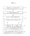
- a femto cell connection node includes: a connection state detection unit for checking a connection state of a receiving terminal when a data transmission request for the receiving terminal is received from a sending terminal; and a protocol support processing unit for changing a transmission format of data received from the sending terminal according to the connection state of the receiving terminal.
- a femto cell connection node supporting the sending terminal checks a connection state of the receiving terminal, and the femto cell connection node determines a transmission format of the data to be transmitted to the receiving terminal according to the connection state of the receiving terminal.
- a femto cell system using a femto cell includes: a sending terminal; and a femto cell connection node wirelessly connected to the sending terminal, receiving a data transmission request for a receiving terminal from the sending terminal, checking a connection state of the receiving terminal to determine a transmission format according to the connection state of the receiving terminal, changing a transmission format of the data received from the sending terminal according to the determined transmission format, and transmitting the data.
- a terminal connected to HeNB communicates with a terminal connected to another HeNB or directly connected to the IP network
- FIGS. 1 to 3 a femto cell system according to a preferred embodiment of the present disclosure will be described in detail with reference to FIGS. 1 to 3 .
- FIG. 1 is a schematic view showing the femto cell system according to one embodiment of the present invention.
- FIG. 1 exemplarily shows a configuration for performing efficient data transmission using an Internet Protocol (IP) network in a mobile communication system using femto cells.
- IP Internet Protocol
- Macro cell connection nodes such as base stations, node B and evolved Node B (eNB) should be connected to a dedicated line used in a core network of a mobile communication service provider and perform voice and data communication by using the dedicated line.
- femto cell connection nodes may be connected to the core network even through an IP network installed indoors or in an office.
- Home NodeB (HNB) and Home eNodeB (HeNB) are representative examples of the femto cell connection node.
- a data traffic load in a core network of a mobile communication system is reduced using the above features of the femto cell connection node, thereby improving the performance.
- a sending terminal 110 and a femto cell connection node#1 131 are located at a sending side.
- a core network such as Evolved Packet Core (EPC), or a receiving terminal#1 121 to a receiving terminal#3 123 linked to an IP network, a femto cell connection node#2 132, and a macro cell connection node 160 are located at a receiving side.
- EPC Evolved Packet Core
- the receiving terminal#1 121 to the receiving terminal#3 123 are generally called a 'receiving terminal 120 ', and the femto cell connection node#1 131 and the femto cell connection node#2 132 are generally called a 'femto cell connection node 130', if required.
- the sending terminal 110 sends a data transmission request for the receiving terminal 120 by call transmission to the femto cell connection node#1 131 supporting the sending terminal 110, and transmits data to the femto cell connection node#1 131 if a response is received.
- the receiving terminal 120 is a device receiving data from the sending side via various paths through a core network or an IP network, and the receiving terminal#1 121, the receiving terminal#2 122, and the receiving terminal#3 123 exemplarily show various traffic paths for data receipt.
- the receiving terminal#1 121 receives data transmitted from the sending terminal 110 through the macro cell connection node 160 linked with the core network.
- the receiving terminal#2 122 exemplarily shows a terminal connected to the IP network through the femto cell connection node#2 132, and the receiving terminal#3 123 exemplarily shows a terminal directly connected to the IP network.
- the receiving terminals 120 may periodically determine using a cell ID whether it is connected to the femto cell connection node 130 (e.g., the femto cell connection node#2 132) or the macro cell connection node 160 in order to receive communication service.
- the determination result may be sent to an uplink device (e.g., a femto cell gateway 140 or a core network node 150) connected thereto.
- the femto cell connection node#1 131 is a sending connection node wirelessly connected to the sending terminal 110 and directly connected to the IP network to operate. If the data transmission request for the receiving terminal 120 is received from the sending terminal 110, the femto cell connection node#1 131 checks a connection state of the corresponding receiving terminal 120 and determines a transmission format of the data according to the connection state of the receiving terminal 120. In addition, the femto cell connection node#1 131 changes the transmission format of the data received from the sending terminal 110 according to the determined transmission format and then sends the corresponding data to the receiving terminal 120 through the IP network or the core network.
- the femto cell connection node#1 131 may change the data received from the sending terminal 110 into a transmission format suitable for the IP network, instead of tunneling the data suitably for the core network, and then send the data to the receiving terminal 120 through the IP network.
- the sending terminal 110 communicates with the receiving terminal#2 122 or the receiving terminal#3 123 may belong to the above case.
- the femto cell connection node#2 132 is a receiving connection node at the data receiving side, which is wirelessly connected to the receiving terminal 120 and plays a role of receiving the data sent from the sending terminal 110 through the IP network and sending the received data to the receiving terminal#2 122.
- the femto cell connection node#2 132 may be Home eNodeB (HeNB, Femto Cell BTS in LTE).
- the femto cell gateway 140 is a device located at the sending side or the receiving side to interconnect the femto cell connection nodes 130 managing terminals such as the sending terminal 110 and the receiving terminal 120 and to link the femto cell connection nodes 130 to the IP network.
- the femto cell connection node 130 may be connected through the femto cell gateway 140 to the core network node 150, or may be directly connected to the core network node 150.
- the femto cell gateway 140 may be Home eNodeB Gateway (HeNB GW). In the case where the femto cell connection node 130 is directly connected to the core network node 150, the femto cell gateway 140 may be excluded.
- HeNB GW Home eNodeB Gateway
- the core network node 150 in the core network manages the macro cell connection node 160.
- the core network node 150 controls the macro cell connection node 160 to enable communication between the sending side and the receiving side.
- the core network may include Serving Gateway (S-GW), Packet Data Network (PDN) Gateway (P-GW), Mobility Management Entity (MME) and so on, among which MME may operate as the core network node 150.
- S-GW Serving Gateway
- PDN Packet Data Network
- P-GW Packet Data Network Gateway
- MME Mobility Management Entity
- the core network node 150 may perform functions such as Non-Access Stratum (NAS) signaling or security, inter core-network signaling for mobility of terminals, P-GW/S-GW selection, selection of another MME or another SGSN at the handover accompanied with MME change or serving GPRS support node (SGSN) change, roaming, authentication and so on.
- the S-GW may perform functions such as management of Local Mobility Anchor (LMA) point for handover, packet routing or forwarding, and so on.
- LMA Local Mobility Anchor
- the P-GW may perform functions such as packet filtering, terminal IP address allocation and so on.
- the macro cell connection node 160 is a device connected to the data sending side through the core network, and is supported by the core network node 150 to send the data received from the sending terminal 110 to the receiving terminal 120.
- the macro cell connection node 160 may be evolved Node B (eNB).
- the macro cell connection node 160 may perform functions such as radio bearer control, radio admission control, connection mobility control, frequency management such as scheduling, data encoding of IP header and user data, routing, scheduling of paging message and broadcasting message, measurement, measurement reporting and so on.
- functions such as radio bearer control, radio admission control, connection mobility control, frequency management such as scheduling, data encoding of IP header and user data, routing, scheduling of paging message and broadcasting message, measurement, measurement reporting and so on.
- one sending terminal 110 receives outdoors mobile communication service at the macro cell connection node 160 (e.g., eNB) connected to the core network, and when entering an indoor femto cell region, the sending terminal 110 receives mobile communication service from the femto cell connection node 130 (e.g., HeNB).
- the femto cell connection node 130 e.g., HeNB
- the femto cell connection node 130 is connected to the IP network by using an IP network line installed indoors and is connected to the core network of the mobile communication system through the IP network.
- the femto cell system transforms the data transmission format not suitably for the core network (e.g., EPC) but suitably for the IP network so as to allow data communication directly through the IP network without passing the core network.
- This operation may be performed in the case where the sending terminal 110 connected to the femto cell connection node#1 131 (e.g., HeNB) communicates with the receiving terminal#2 122 connected to another femto cell connection node#2 132 (e.g., HeNB), or in the case where the sending terminal 110 communicates with the receiving terminal#3 123 directly connected to the IP network.
- the core network e.g., EPC
- IP network e.g., IP network
- direct communication may be performed through the IP network without passing the core network of the mobile communication system.
- the load of the core network in the mobile communication system may be reduced according to one embodiment of the present disclosure, and accordingly the overall receiving capacity may increase.
- unnecessary data paths decrease to shorten the data traffic path, it is possible to reduce data delay.
- a user may reduce service costs by using the cheap IP network at maximum, instead of using an expensive interface provided by a mobile communication service provider.
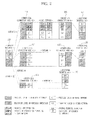
- FIG. 2 shows the change of a data structure passing the femto cell system of FIG. 1 .
- the sending terminal 110 sends a data transmission request for the receiving terminal 120 to the femto cell connection node#1 131.
- the sending terminal 110 transmits a call initiating request message (CalllnitReq) requesting data transmission for the receiving terminal 120 to the femto cell connection node#1 131.
- the femto cell connection node#1 131 supporting the sending terminal 110 checks a connection state of the receiving terminal 120, and determines a transmission format of the data to be sent to the corresponding receiving terminal 120 according to the connection state of the receiving terminal 120.
- the femto cell connection node#1 131 receiving the message sends a terminal information request message (UElnfoReq) requesting the connection state of the receiving terminal 120 to its uplink device (e.g., the femto cell gateway, the core network node or the like) and receives connection state information of the receiving terminal as a response.
- UElnfoReq terminal information request message
- the connection state of the receiving terminal 120 may be classified into any one of a core network connection state passing via the core network provided by a mobile communication service provider at data communication, and an IP network connection state using the IP network distinguished from the core network or provided by Internet Service Provider (ISP) at data communication.
- the receiving terminal#1 121 may be considered as the core network connection state connected to the macro cell connection node connected to the core network.
- the receiving terminal#2 122 connected to the IP network through the femto cell connection node#2 132 and the receiving terminal#3 123 directly connected to the IP network may be considered as the IP network connection state.
- the femto cell connection node#1 131 receives data from the sending terminal 110 and changes the data into a transmission format suitable for the IP network.
- the femto cell connection node#1 131 receives data from the sending terminal 110 and changes the data into a transmission format suitable for the core network.
- each terminal may periodically determine by using the cell ID whether it is connected to the femto cell connection node 130 or the macro cell connection node 160, and notify the determination result to its uplink device (e.g., the femto cell gateway 140, the core network node 150 or the like).
- its uplink device e.g., the femto cell gateway 140, the core network node 150 or the like.
- each terminal may receive the cell ID from the connection node (e.g., the femto cell connection node 130 or the macro cell connection node 160) connected thereto.
- the connection node e.g., the femto cell connection node 130 or the macro cell connection node 160
- FIG. 2 is for illustrating the data format changing process according to the present disclosure.
- the femto cell connection node#1 131 is connected to an IP network installed indoors, and is connected to the core network (e.g., EPC) of a mobile communication service provider through the IP network.
- EPC the core network
- the femto cell connection node#1 131 of the sending side, the femto cell connection node#2 132 of the receiving side, and the core network are all included in the data traffic path.
- the process is as follows.
- the femto cell connection node#1 131 may tunnel the data received from the sending terminal 110 in the GPRS Tunneling Protocol/User Datagram Protocol/Internet Protocol (GTP/UDP/IP) manner and send the data to the core network.
- the traffic of the data passing via the core network is transmitted through the IP network again to the femto cell connection node#2 132 (e.g., HeNB) where the receiving terminal 120 which is an opponent is located.
- GTP/UDP/IP GPRS Tunneling Protocol/User Datagram Protocol/Internet Protocol
- the data is changed again into a Transmission Control Protocol/Internet Protocol (TCP/IP) format used in the IP network and then transmitted in order to pass via the IP network.
- TCP/IP Transmission Control Protocol/Internet Protocol
- the traffic of the data reaching the opponent femto cell connection node#2 132 e.g., HeNB is transmitted to the receiving terminal 120.
- the data should be transmitted basically via the core network, similar to the above process.
- the scenario I exemplarily shows the format change of a data structure at such a data flow.
- the scenario I always passing via the core network is not efficient.
- a scenario II or a scenario III is suggested as a data path along which data may be efficiently transmitted using the IP network.
- both of the sending terminal 110 which is willing to send or receive data and the receiving terminal 120 are connected to the femto cell connection node 130 (e.g., HeNB), or in the case where one terminal is connected to the femto cell connection node 130 (e.g., HeNB) and the other terminal is directly connected to the IP network, the following scenario II or III may be applied.
- the femto cell connection node 130 e.g., HeNB
- the sending terminal 110 and the receiving terminal 120 respectively need to check whether they are connected to the femto cell connection node 130. This may be determined using the cell ID received from the femto cell connection node 130.
- the femto cell connection node 130 has a cell ID distinguished from the macro cell connection node 160.
- the macro cell connection nodes e.g., eNB
- the femto cell connection nodes e.g., HeNB
- the femto cell connection nodes are endowed with cell IDs over 0x2000, and the IDs of the femto cell connection nodes are distinguished from the macro cell connection nodes.
- Each terminal may receive a message notifying the connection node information such as a paging channel message from the connection node connected thereto, check its cell ID, and then determine whether it is connected to the femto cell connection node (e.g., HeNB) or the macro cell connection node (e.g., eNB).
- the connection node information such as a paging channel message from the connection node connected thereto
- the cell ID e.g., HeNB
- eNB macro cell connection node
- Each terminal needs to periodically notify to the uplink deice (e.g., MME) whether the connection node connected thereto at the present is the macro cell connection node (e.g., eNB) or the femto cell connection node (e.g., HeNB).
- MME uplink deice
- the core network may periodically request the corresponding information to each terminal, or each terminal may periodically notify the corresponding information to the core network.
- the femto cell connection node 130 (e.g., HeNB) of the sending terminal 110 sending data checks whether the receiving terminal 120 is connected to the femto cell connection node (e.g., HeNB) or directly connected to the IP network, and then transmits data according to the scenario II or III of FIG. 2 .
- the femto cell connection node 130 (e.g., HeNB) of the sending terminal 110 sending data checks whether the receiving terminal 120 is connected to the femto cell connection node (e.g., HeNB) or directly connected to the IP network, and then transmits data according to the scenario II or III of FIG. 2 .
- the data may be transmitted according to the scenario I.
- the macro cell connection node 160 e.g., eNB
- FIG. 3 shows an inner configuration of the femto cell connection node of FIG. 1 , and an inner configuration of the femto cell connection node#1 131 located at the sending side is illustrated as an example.
- the opponent receiving terminal 120 is connected to the femto cell connection node 130 (e.g., femto cell connection node#2 132) (for example, the receiving terminal#2 122) or directly connected to the IP network (for example, the receiving terminal#3 123), the femto cell connection node#1 131 of the sending side may communicate with the receiving side directly through the IP network.
- the femto cell connection node#1 131 uses a signaling technique to check a state of the receiving terminal 120 which is an opponent for data exchange.
- the femto cell connection node#1 131 changes a data format suitably for the checked state of the receiving side. For example, this operation may be performed in the case where the receiving terminal 120 is directly connected to the IP network or located at a local network after checking their states.
- the femto cell connection node#1 131 allows communication using the IP network with an efficient data format by making the data in a format available in the IP network, not in a format suitable for the core network interface of the mobile communication system.
- the femto cell connection node#1 131 includes a connection state detection unit 133 and a protocol support processing unit 135, and a data format determining unit 134 may be further included.
- the connection state detection unit 133 checks a connection state of the receiving terminal 120. For example, if a call initiating request message (CallInitReq) requesting data transmission for the receiving terminal 120 is received from the sending terminal 110, the connection state detection unit 133 generates a terminal information request message (UEInfoReq) requesting a connection state of the receiving terminal 120 as a response.
- the connection state detection unit 133 may transmit the terminal information request message (UEInfoReq) to the uplink device (e.g., MME) and then receive the connection state of the receiving terminal 120 from the corresponding uplink device (e.g., MME) as a response to the terminal information request message (UEInfoReq).
- the uplink device e.g., MME
- MME uplink device
- the connection state of the receiving terminal 120 may be classified into a core network connection state and an IP network connection state.
- the core network connection state is a state passing via the core network provided by the mobile communication service provider at data communication
- the IP network connection state is a state distinguished from the core network or passing via the IP network provided by the ISP at data communication.
- the core network connection state may mean a state where the receiving terminal 120 is connected to the macro cell connection node (e.g., receiving terminal#1 121).
- the IP network connection state may mean a state where the receiving terminal 120 is connected to the femto cell connection node connected to the IP network (e.g., the receiving terminal#2 122), or a state directly connected to the IP network (e.g., the receiving terminal#3 123).
- the data format determining unit 134 determines a transmission format of the data transmitted from the sending terminal 110 to the receiving terminal 120 according to the connection state of the receiving terminal 120 checked by the connection state detection unit 133, and notifies the result to the protocol support processing unit 135.
- the protocol support processing unit 135 changes a transmission format of the data received from the sending terminal 110 according to the connection state of the corresponding receiving terminal 120 so that the data may be transmitted to the receiving terminal 120.
- the protocol support processing unit 135 may change the data received from the sending terminal 110 into a transmission format suitable for the IP network and then transmit the data to the receiving terminal 120 through the IP network.
- the protocol support processing unit 135 may include an IP network protocol supporting unit 136 and a core network protocol supporting unit 137.
- the IP network protocol supporting unit 136 receives data from the sending terminal 110 and changes the data into a transmission format suitable for the IP network in the state where the receiving terminal 120 is in the IP network connection state.
- the IP network protocol supporting unit 136 may include a femto cell connection supporting unit 138 and an IP direct connection supporting unit 139.
- the femto cell connection supporting unit 138 in the femto cell connection node#1 131 of the sending side changes a protocol structure as in the scenario II of FIG. 2 .
- the protocol region L1 (Physical Layer)/L2 (Transport Layer) for wireless region transmission is changed to a protocol structure L1 (Physical Layer)/L2 (Transport Layer)/TCP (Transmission Control Protocol)/IP (Internet Protocol).
- L1/L2 is for the transmission in a wired network
- TCP/IP is an IP protocol structure, where IP is an address for the connection to the femto cell connection node#2 132 connected to the receiving terminal 120.
- the IP direct connection supporting unit 139 changes a transmission format of the data as in the scenario III.
- the protocol portion L1 (Physical Layer)/ L2 (Transport Layer) for the wireless region transmission is changed to the L1 (Physical Layer)/L2 (Transport Layer) in a wired network.
- the core network protocol supporting unit 137 receives data from the sending terminal 110 and changes the data into a transmission format suitable for the core network in the case where the receiving terminal 120 is in the core network connection state (e.g., the receiving terminal#1 121).
- the core network protocol supporting unit 137 of the femto cell connection node#1 131 changes, in the data received from the sending terminal 110, the protocol portion L1 (Physical Layer)/L2 (Transport Layer) for the wireless region transmission to a protocol structure L1 (Physical Layer)/L2 (Transport Layer)/GTP (GPRS Tunneling Protocol)/UDP (User Datagram Protocol)/IP (Internet Protocol) as in the scenario I.
- L1/L2 is for the transmission in a wired network
- GTP/UDP is for the transmission in the core network
- IP is a private IP address.
- the femto cell connection node#1 131 of the sending terminal 110 may check whether the receiving terminal 120 is connected to the femto cell connection node 130 (e.g., HeNB) or directly connected to the IP network, by means of the signaling technique of FIGS. 4 to 6 .
- the femto cell connection node 130 e.g., HeNB
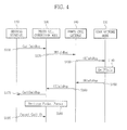
- FIG. 4 is a flowchart for illustrating a data transmission method of the femto cell system according to one embodiment of the present disclosure.
- FIG. 4 exemplarily shows a process in which, in the case where the femto cell gateway 140 (e.g., HeNB GW) is present, the femto cell connection node 130 (e.g., HeNB) of the sending side checks connection state information of the receiving terminal 120 and determines a transmission method of data such as traffic and packet.
- the femto cell gateway 140 e.g., HeNB GW
- the femto cell connection node 130 e.g., HeNB
- the connection state information may be information notifying whether the receiving terminal 120 is connected to the connection node 160 (e.g., eNB) supporting macro cells, connected to the connection node 130 (e.g., HeNB) supporting femto cells, or directly connected to the IP network where a connected location may be checked.
- the connection node 160 e.g., eNB
- the connection node 130 e.g., HeNB
- femto cells femto cells
- the femto cell connection node 130 of the sending side checks the connection state information of the receiving terminal 120, which may be obtained from the core network. After that, the femto cell connection node 130 may enhance the transmission efficiency by selectively applying two manners, namely a manner of transmitting data via the core network provided by a mobile communication service provider and a manner of sending data using the IP network distinguished from the core network, provided by a general ISP or provided through an IP, according to circumstances.
- FIG. 4 exemplarily shows the case where the sending terminal 110 transmits data.
- the Mobility Management Entity (MME) operated as the core network node 150 plays a role of storing user location information and manages a terminal in Tracking Area (TA) unit. If TA is changed, the terminal notifies TA information about its location to the MME through a Tracking Area Update (TAU) process. At a specific point of time, the terminal registers its location to only one MME.
- MME Mobility Management Entity
- TAU Tracking Area Update
- the sending terminal 110 transmits a call initiating request message (CallInitReq) requesting data transmission for the receiving terminal 120 to the connected femto cell connection node 130 (S110).
- the call initiating request message (CallInitReq) is a message requesting the sending terminal 110 to make a call to a desired opponent.
- the call initiating request message (CallInitReq) may include ID of the receiving terminal 120 which is a call opponent, service ID, kind of service, and so on.
- the femto cell connection node 130 As the call initiating request message (CallInitReq) is received, the femto cell connection node 130 generates a terminal information request message (UEInfoReq) inquiring a connection state of the receiving terminal 120. After that, the femto cell connection node 130 transmits the terminal information request message (UEInfoReq) to the uplink devices, namely the femto cell gateway 140 and the core network node 150, in order (S120, S130), and receives a connection state of the receiving terminal 120 from the femto cell gateway 140 as a response (S140 to S160).
- UEInfoReq terminal information request message
- the femto cell connection node 130 receives the call initiating request message (CallInitReq) from the sending terminal 110 and then generates transmits the terminal information request message (UEInfoReq) to the femto cell gateway 140 (S120).
- the terminal information request message (UEinfoReq) is a message requesting connection state information of a desired opponent.
- the terminal information request message (UEinfoReq) may include ID of the receiving terminal 120 which is a call opponent, service ID, kind of service, and so on.
- the femto cell gateway 140 receives the terminal information request message (UEinfoReq) from the femto cell connection node 130 and then transmits the message to the core network node 150 (S130).
- the terminal information request message (UEInfoReq) is a message requesting connection state information of the receiving terminal 120 which is a call opponent.
- the terminal information request message (UEinfoReq) may include ID of the receiving terminal 120 which is a call opponent, service ID, kind of service, and so on.
- the core network node 150 receives the terminal information request message (UEInfoReq) from the femto cell gateway 140 and then checks the connection state information of the receiving terminal 120 (S140).
- the core network node 150, the MME may recognize the connection state information or location information of the receiving terminal 120.
- the core network node 150 may recognize whether the receiving terminal 120 is connected in a state of the receiving terminal#2 122 shown in FIGS. 1 and 2 (scenario II) or connected in a state of the receiving terminal#1 121 (scenario I) according to the connection state information.
- the receiving terminal 120 is registered in a specific server connected to the IP network or connected to the server, it may be understood that it is in a connection state like the receiving terminal#3 123.
- the core network node 150 checks the connection state information of the receiving terminal 120 and then transmits the terminal information notifying message (UEInfoRsp) to the femto cell gateway 140 (S150).
- the terminal information notifying message (UEInfoRsp) is a response message notifying the connection state information of the receiving terminal 120.
- the terminal information notifying message (UEInfoRsp) includes the connection state information of the receiving terminal 120 checked by the core network node 150.
- the femto cell gateway 140 receives the terminal information notifying message (UEInfoRsp) from the core network node 150, and then transmits the terminal information notifying message (UEInfoRsp) to the femto cell connection node 130 (S160).
- the terminal information notifying message (UEInfoRsp) is a response message notifying the connection state information of the receiving terminal 120 and includes the connection state information of the receiving terminal 120 checked by the core network node 150.
- the femto cell connection node 130 receives the terminal information notifying message (UEInfoRsp) from the femto cell gateway 140, and then transmits the call initiating response message (CallInitRsp) to the sending terminal 110 (S170).
- the call initiating response message (CallInitRsp) is a message notifying that the sending terminal 110 may send user data.
- the femto cell connection node 130 determines a transmission format of user data to be transmitted according to the connection state information of the receiving terminal 120 included in the terminal information notifying message (UElnfoRsp) (S180).
- the data may be transmitted in a packet format as in the scenario II of FIG. 2 .
- connection state information is identical to the receiving terminal#1 121, in other words if the receiving terminal 120 is in a state of being connected to the macro cell connection node 160, the data may be transmitted in a packet format as in the scenario I.
- connection state information is identical to the receiving terminal#3 123, in other words if the receiving terminal 120 is in a state of being connected through the IP network, the data may be transmitted in a packet format as in the scenario III.
- the core network node 150 or the femto cell gateway 140 may recognize the corresponding connection state as a specific server or the like on the IP network notifies the state where the receiving terminal 120 is registered or connected.
- the determining the packet format (S180) may be executed at the same time as or before the transmitting the call initiating response message (CallInitRsp) (S170), or may be executed after a packet call transmission message (Packet Call Tx) is received (S190). If the sending terminal 110 receiving the call initiating response message (CallInitRsp) transmits the user data to be sent to the receiving side by using the packet call transmission message (Packet Call Tx) (S190), the femto cell connection node 130 transmits the corresponding data to the receiving side in the determined packet format.
- FIG. 5 is a flowchart for illustrating a data transmission method of the femto cell system according to another embodiment of the present disclosure.
- FIG. 5 shows the process of checking the connection state information in a way that the femto cell connection node 130 (e.g., HeNB) transmits the terminal information request message (UEInfoReq) directly to the core network node 150 (e.g., MME) without passing through the femto cell gateway 140 (e.g., HeNB GW).
- the femto cell connection node 130 may be directly connected to and communicate with the core network node 150 without passing through the femto cell gateway 140.
- the sending terminal 110 transmits the call initiating request message (CallInitReq) to the connected femto cell connection node 130 (S210).
- the call initiating request message (CallInitReq) is a message requesting the sending terminal 110 to communicate with a desired opponent.
- the call initiating request message (CallInitReq) includes ID of the receiving terminal 120 which is a call opponent, service ID, kind of service, and so on.
- the femto cell connection node 130 receives the call initiating request message (CallInitReq) from the sending terminal 110 and then transmits the terminal information request message (UEInfoReq) to the core network node 150 (S220).
- the terminal information request message (UEInfoReq) is a message requesting connection state information of a desired opponent.
- the terminal information request message (UEInfoReq) includes ID of the receiving terminal 120 which is a call opponent, service ID, kind of service, and so on.
- the core network node 150 receives the terminal information request message (UEInfoReq) from the femto cell connection node 130 and then checks the connection state information of the receiving terminal 120 (S230).
- UEInfoReq terminal information request message
- the core network node 150 may recognize the connection state information or location information of the receiving terminal 120, and may recognize whether the receiving terminal 120 is connected in the state of the receiving terminal#1 121 of FIGS. 1 and 2 or connected in the state of the receiving terminal#2 122 according to the connection state information. In the case where the receiving terminal 120 is registered in a specific server connected to the IP network or connected to the corresponding server, it may be understood to be in same connection state as the receiving terminal#3 123.
- the core network node 150 checks the connection state information of the receiving terminal 120 and then transmits the terminal information request message (UEInfoRsp) to the femto cell connection node 130 (S240).
- the terminal information request message (UEInfoRsp) is a response message notifying the connection state information of the receiving terminal 120 and includes the connection state information of the receiving terminal 120 checked by the core network node 150.
- the femto cell connection node 130 receives the terminal information request message (UEInfoRsp) from the core network node 150, and then transmits the call initiating response message (CallInitRsp) to the sending terminal 110 (S250).
- the call initiating response message (CallInitRsp) is a message notifying that the sending terminal 110 may send the user data.
- the femto cell connection node 130 determines a packet format of the user data to be transmitted according to the connection state information of the receiving terminal 120 included in the received terminal information notifying message (UEinfoRsp) (S260).
- the connection state information is identical to the receiving terminal#2 122, in other words if the receiving terminal 120 is in a state of being connected through the femto cell connection node 130 (e.g., HeNB), the data may be transmitted in the packet format as in the scenario II of FIG. 2 .
- the femto cell connection node 130 e.g., HeNB
- connection state information is identical to the receiving terminal#1 121, in other words if the receiving terminal 120 is in a state of being connected to the macro cell connection node 160 (e.g., eNB) of the core network, the data may be transmitted in the packet format as in the scenario I of FIG. 2 .
- the macro cell connection node 160 e.g., eNB
- connection state information is identical to the receiving terminal#3 123, in other words if the receiving terminal 120 is in a state of being connected through the IP network, the data may be transmitted in the packet format as in the scenario III of FIG. 2 .
- the uplink device of the core network node 150 may recognize whether a terminal is registered or connected through a specific server.
- the determining packet format (S260) of FIG. 5 may be executed at the same time as or before the transmitting the call initiating response message (CallInitRsp) (S250), or after the packet call transmission message (Packet Call Tx) is received (S270).
- FIG. 6 is a flowchart for illustrating a data transmission method of the femto cell system according to still another embodiment of the present disclosure.
- FIG. 6 shows the process of checking the connection state information in a way of sending a terminal information request message (UEInfoReq) to the femto cell gateway 140 without passing through the core network node 150.
- UEInfoReq terminal information request message
- the femto cell gateway 140 may store the connection state information or location information of terminals connected through the femto cell connection node 130 managed by the femto cell gateway 140, and may download (or, receive) and store the connection state information or location information from the core network node 150.
- HeNB GW HeNB GW
- terminals connected to the core network or the IP network through the femto cell connection node 130 managed by the femto cell gateway 140 perform a process of notifying the core network node 150 through the corresponding femto cell gateway 140 that they are connected to the corresponding femto cell gateway 140.
- the femto cell gateway 140 may recognize that the receiving terminal 120 is connected through the femto cell connection node 130, and may store the connection state information of the receiving terminal 120.
- the sending terminal 110 attempts a call
- the connection state information of the receiving terminal 120 may be found at the femto cell gateway 140.
- the receiving terminal 120 may also recognize the connection state information of the sending terminal 110 managed by the femto cell gateway 140 at the femto cell gateway 140.
- the femto cell gateway 140 may transmit a message requesting the connection state information of the receiving terminal 120 again to the core network node 150 (e.g., MME).
- the core network node 150 e.g., MME
- the sending terminal 110 transmits the call initiating request message (CallInitReq) to the connected femto cell connection node 130 (S310).
- the call initiating request message (CallInitReq) is a message requesting the sending terminal 110 to make a call to a desired opponent.
- the call initiating request message (CallInitReq) may include ID of the receiving terminal 120 which is a call opponent, service ID, kind of service, and so on.
- the femto cell connection node 130 receives the call initiating request message (CallInitReq) from the sending terminal 110, and then transmits the terminal information request message (UEInfoReq) to the femto cell gateway 140 (S320).
- the terminal information request message (UEInfoReq) is a message requesting the connection state information of a desired opponent.
- the terminal information request message (UEInfoReq) may include ID of the receiving terminal 120 which is a call opponent, service ID, kind of service, and so on.
- the femto cell gateway 140 receives the terminal information request message (UEInfoReq) from the femto cell connection node 130, and then checks the connection state information of the receiving terminal 120 (S330).
- the femto cell gateway 140 may recognize the connection state information or location information of the receiving terminal 120, and may recognize whether the receiving terminal 120 is connected in the state of the receiving terminal#1 121 of FIGS. 1 and 2 or connected in the state of the receiving terminal#2 122 according to the connection state information.
- the receiving terminal 120 In the state where the receiving terminal 120 is registered in a specific server connected to the IP network or connected to the corresponding server, it may be recognized to be in the same connection state as the receiving terminal#3 123. In the case where the information of the receiving terminal 120 is not found in the femto cell gateway 140, the femto cell connection node 130 may transmit the terminal information request message (UEInfoReq) to the core network node 150 so that the connection state information of the corresponding receiving terminal 120 may be recognized.
- UEInfoReq terminal information request message
- the femto cell gateway 140 checks the connection state information of the receiving terminal 120 and then transmits the terminal information notifying message (UEInfoRsp) to the femto cell connection node 130 (S340).
- the terminal information notifying message (UEInfoRsp) is a response message notifying the connection state information of the receiving terminal 120, and includes the connection state information of the receiving terminal 120 checked by the femto cell gateway 140.
- the femto cell connection node 130 receives the terminal information notifying message (UEInfoRsp) from the femto cell gateway 140, and then transmits the call initiating response message (CallInitRsp) to the sending terminal 110 (S350).
- the call initiating response message (CallInitRsp) is a message notifying that the sending terminal 110 may send user data.
- the femto cell connection node 130 determines a packet format of the user data to be transmitted according to the connection state information of the receiving terminal 120 included in the received terminal information notifying message (UEinfoRsp) (S360).
- the connection state information is identical to the receiving terminal#2 122, in other words if the receiving terminal 120 is in the state of being connected through the femto cell connection node 130 (e.g., HeNB), the data may be transmitted in the packet format as in the scenario II of FIG. 2 .
- the femto cell connection node 130 e.g., HeNB
- connection state information is identical to the receiving terminal#1 121, in other words if the receiving terminal 120 is in the state of being connected to the macro cell connection node 160 (e.g., eNB), the data may be transmitted in the packet format as in the scenario I of FIG. 2 .
- the macro cell connection node 160 e.g., eNB
- connection state information is identical to the receiving terminal#3 123, in other words if the receiving terminal 120 is in the state of being connected through the IP network and the registration or connection state of the terminal is transmitted through a specific server so that the femto cell gateway 140 (or, the core network node 150) recognizes the corresponding connection state, the data may be transmitted in the packet format as in the scenario III of FIG. 2 .
- the determining packet format determining (S360) of FIG. 6 may be executed at the same time as or before the transmitting the call initiating response message (CallInitRsp) (S350), or may be executed after the packet call transmission message (Packet Call Tx) is received from the sending terminal 110 (S370).
- the sending terminal 110 transmits data in a data format suitable for the core network without any change from the conventional case.
- the femto cell connection node 130 of the sending side receiving data from the sending terminal recognizes that the data transmission manner determined according to the connection state information of the receiving terminal 120 is the scenario II or III.
- the femto cell connection node 130 changes the data format as in the method of FIGS. 1 and 2 without making a data format in a conventional tunneling manner and transmits the data to the femto cell connection node 130 (e.g., HeNB) to which the receiving terminal 120 is connected, so that the data may pass through the IP network.
- the femto cell connection node 130 e.g., HeNB
- the femto cell connection node 130 of the receiving side which receives the data forwards the received data to the receiving terminal 120.
- the femto cell connection node 130 of the sending side recognizes the scenario III.
- the femto cell connection node 130 changes only the L1/L2 protocol portion to pass through the IP network, without making data in a conventional tunneling manner, and transmits the data to the receiving terminal 120.
- the receiving terminal 120 since the receiving terminal 120 is not connected to the femto cell connection node 130, the data may be directly received.
- the present disclosure is not limited to HeNB or any specific base station but may be applied all kinds of connection nodes connected to the IP network.
- the present disclosure may include all kinds of connection manners, without being limited to wireless connection techniques such as CDMA, OFDMA, and TDMA, and may similarly include all kinds of service manners such as WiBro, LTE, and WiMax, without being limited to a specific service.
- the femto cell connection node, the femto cell system, and the data transmission method of the system according to the present disclosure may reduce the load of a core network, accordingly increase an overall receiving capacity of the system, and reduce unnecessary data paths to shorten a path of data traffic, thereby reducing the data delay.
Landscapes
- Engineering & Computer Science (AREA)
- Computer Networks & Wireless Communication (AREA)
- Signal Processing (AREA)
- Databases & Information Systems (AREA)
- Mobile Radio Communication Systems (AREA)
Applications Claiming Priority (2)
| Application Number | Priority Date | Filing Date | Title |
|---|---|---|---|
| KR1020090025096A KR101034932B1 (ko) | 2009-03-24 | 2009-03-24 | 펨토 셀 시스템 및 그 시스템의 데이터 전송 방법 |
| PCT/KR2010/001803 WO2010110595A2 (ko) | 2009-03-24 | 2010-03-24 | 펨토 셀 접속노드, 펨토 셀 시스템 및 그 시스템의 데이터 전송 방법 |
Publications (1)
| Publication Number | Publication Date |
|---|---|
| EP2413618A2 true EP2413618A2 (de) | 2012-02-01 |
Family
ID=42781669
Family Applications (1)
| Application Number | Title | Priority Date | Filing Date |
|---|---|---|---|
| EP10756350A Withdrawn EP2413618A2 (de) | 2009-03-24 | 2010-03-24 | Femtozellen-zugangsknoten, femtozellensystem und datenübertragungsverfahren für dieses system |
Country Status (6)
| Country | Link |
|---|---|
| US (1) | US20120009913A1 (de) |
| EP (1) | EP2413618A2 (de) |
| JP (1) | JP2012521710A (de) |
| KR (1) | KR101034932B1 (de) |
| CN (1) | CN102362514A (de) |
| WO (1) | WO2010110595A2 (de) |
Families Citing this family (7)
| Publication number | Priority date | Publication date | Assignee | Title |
|---|---|---|---|---|
| KR20120032644A (ko) * | 2010-09-29 | 2012-04-06 | 주식회사 팬택 | 이동 단말기 및 이동 단말기를 이용한 제어 방법 |
| EP2698036A4 (de) * | 2011-04-12 | 2015-04-15 | Public Wireless Inc | Gemeinsame funkelement-anwendungsverwaltungsarchitektur für drahtlose picozellen |
| US8750835B2 (en) * | 2011-07-26 | 2014-06-10 | Qualcomm Incorporated | Presence-based communication |
| CN103096501B (zh) * | 2011-11-01 | 2016-03-30 | 中国移动通信集团上海有限公司 | 基于毫微微基站系统架构的呼叫系统、方法及装置 |
| JP6179596B2 (ja) | 2013-06-11 | 2017-08-16 | 日本電気株式会社 | 無線基地局、ゲートウェイ装置 |
| JP6341168B2 (ja) * | 2015-09-08 | 2018-06-13 | 京セラドキュメントソリューションズ株式会社 | 情報処理装置、自動設定方法 |
| US11197232B2 (en) * | 2019-04-01 | 2021-12-07 | Ofinno, Llc | Location reporting handling |
Family Cites Families (11)
| Publication number | Priority date | Publication date | Assignee | Title |
|---|---|---|---|---|
| KR100357476B1 (ko) * | 2000-08-18 | 2002-10-19 | (주)클립컴 | 블루투스-인터넷전화 게이트웨이 장치를 이용한 무선인터넷 전화 서비스 시스템 |
| KR100426399B1 (ko) * | 2001-04-06 | 2004-04-08 | 니트젠테크놀러지스 주식회사 | 무선망을 통한 씨디엔 서비스 방법 및 시스템 |
| CN100477856C (zh) * | 2003-04-07 | 2009-04-08 | 华为技术有限公司 | 一种通知上行资源分配的方法 |
| JP2005020545A (ja) * | 2003-06-27 | 2005-01-20 | Oki Electric Ind Co Ltd | Ip電話システム |
| CN1256847C (zh) * | 2003-09-17 | 2006-05-17 | 联想(北京)有限公司 | 动态调整视频传输的方法 |
| KR20050067677A (ko) * | 2003-12-29 | 2005-07-05 | 삼성전자주식회사 | 무선 노드와 외부 인터넷 망과의 통신에서의 데이터 전송장치 및 방법 |
| CN100417276C (zh) * | 2004-05-21 | 2008-09-03 | 华为技术有限公司 | 呼叫状态检测方法 |
| KR100585768B1 (ko) * | 2004-07-09 | 2006-06-07 | 엘지전자 주식회사 | 이동 교환기의 전원 오프 안내 메시지 전송 방법 |
| US20080304462A1 (en) * | 2007-06-05 | 2008-12-11 | Lucent Technologies, Inc. | SESSION INITIATION PROTOCOL/INTERNET PROTOCOL MULTIMEDIA SUBSYSTEM BASED ARCHITECTURE FOR SUPPORTING 3G1x VOICE/DATA |
| US8787302B2 (en) * | 2008-09-18 | 2014-07-22 | Alcatel Lucent | Architecture to support network-wide multiple-in-multiple-out wireless communication over a downlink |
| KR20090038325A (ko) * | 2007-10-15 | 2009-04-20 | 에스케이 텔레콤주식회사 | 펨토셀에서의 부가 장치 연동 시스템 및 그 방법 |
-
2009
- 2009-03-24 KR KR1020090025096A patent/KR101034932B1/ko not_active Expired - Fee Related
-
2010
- 2010-03-24 WO PCT/KR2010/001803 patent/WO2010110595A2/ko not_active Ceased
- 2010-03-24 JP JP2012501936A patent/JP2012521710A/ja active Pending
- 2010-03-24 US US13/257,497 patent/US20120009913A1/en not_active Abandoned
- 2010-03-24 CN CN2010800134557A patent/CN102362514A/zh active Pending
- 2010-03-24 EP EP10756350A patent/EP2413618A2/de not_active Withdrawn
Non-Patent Citations (1)
| Title |
|---|
| See references of WO2010110595A2 * |
Also Published As
| Publication number | Publication date |
|---|---|
| KR101034932B1 (ko) | 2011-05-17 |
| WO2010110595A3 (ko) | 2010-12-09 |
| KR20100106852A (ko) | 2010-10-04 |
| CN102362514A (zh) | 2012-02-22 |
| WO2010110595A2 (ko) | 2010-09-30 |
| JP2012521710A (ja) | 2012-09-13 |
| US20120009913A1 (en) | 2012-01-12 |
Similar Documents
| Publication | Publication Date | Title |
|---|---|---|
| JP6662477B2 (ja) | 最適化されたue中継 | |
| JP6317491B2 (ja) | モバイル通信ネットワーク、インフラストラクチャ機器、モバイル通信端末、および方法。 | |
| CN109076382B (zh) | 在无线通信系统中由基站执行的数据传输方法和使用该方法的装置 | |
| JP6149035B2 (ja) | 通信端末および方法 | |
| US10506394B2 (en) | Communication method of terminal in V2X communication system, and terminal | |
| KR101694085B1 (ko) | 무선 통신 네트워크에서 중계 지원을 핸들링하기 위한 무선 장치, 네트워크 노드 및 방법 | |
| US10588160B2 (en) | Method for handling an ID collision for a D2D communication system and device therefor | |
| US20130322390A1 (en) | Method and apparatus for initiating x2 interface setup in wireless communication system | |
| EP2413618A2 (de) | Femtozellen-zugangsknoten, femtozellensystem und datenübertragungsverfahren für dieses system | |
| US10178584B2 (en) | Method for changing a link connection in a communication system and device therefor | |
| US10111231B2 (en) | Method and apparatus for performing D2D operation in wireless communication system | |
| WO2013191505A1 (en) | Method and apparatus for transmitting indication in wireless communication system | |
| EP2416530B1 (de) | Verfahren, netzwerksystem und einrichtung zur realisierung von datenneuübertragung | |
| KR20100102438A (ko) | 펨토 기지국을 이용한 액세스 제어 방법 및 이를 위한 통신시스템 | |
| WO2013137600A1 (en) | Method and apparatus for determining handover of user equipments attached to mobile relay node in wireless communication system | |
| US9888454B2 (en) | Method and apparatus for efficient mobility management in heterogeneous network environment | |
| KR101383294B1 (ko) | 데이터 오프로딩 접속을 제어하는 기지국 장치 및 가상화 기지국 시스템 | |
| KR101648523B1 (ko) | Pdn 게이트웨이 기능을 가지도록 확장된 펨토 기지국을 포함하는 네트워크 구조에서 효율적인 로컬 ip 액세스 데이터 경로의 설정을 지원하는 방법과 절차 및 장치 | |
| JP5821434B2 (ja) | ネットワーク接続装置およびネットワーク接続方法 | |
| JP6020693B2 (ja) | ネットワーク接続装置およびネットワーク接続方法 | |
| KR20120074833A (ko) | 옥내용 기지국에 연결된 단말들 간의 직접 통신을 위한 방법 및 그러한 옥내용 기지국 |
Legal Events
| Date | Code | Title | Description |
|---|---|---|---|
| PUAI | Public reference made under article 153(3) epc to a published international application that has entered the european phase |
Free format text: ORIGINAL CODE: 0009012 |
|
| 17P | Request for examination filed |
Effective date: 20110916 |
|
| AK | Designated contracting states |
Kind code of ref document: A2 Designated state(s): AT BE BG CH CY CZ DE DK EE ES FI FR GB GR HR HU IE IS IT LI LT LU LV MC MK MT NL NO PL PT RO SE SI SK SM TR |
|
| DAX | Request for extension of the european patent (deleted) | ||
| STAA | Information on the status of an ep patent application or granted ep patent |
Free format text: STATUS: THE APPLICATION IS DEEMED TO BE WITHDRAWN |
|
| 18D | Application deemed to be withdrawn |
Effective date: 20141001 |