EP2413552B1 - Method and device for determining smooth window length in channel estimation - Google Patents
Method and device for determining smooth window length in channel estimation Download PDFInfo
- Publication number
- EP2413552B1 EP2413552B1 EP20110175203 EP11175203A EP2413552B1 EP 2413552 B1 EP2413552 B1 EP 2413552B1 EP 20110175203 EP20110175203 EP 20110175203 EP 11175203 A EP11175203 A EP 11175203A EP 2413552 B1 EP2413552 B1 EP 2413552B1
- Authority
- EP
- European Patent Office
- Prior art keywords
- value
- autocorrelation
- speed range
- length
- values
- Prior art date
- Legal status (The legal status is an assumption and is not a legal conclusion. Google has not performed a legal analysis and makes no representation as to the accuracy of the status listed.)
- Active
Links
Images
Classifications
-
- H—ELECTRICITY
- H04—ELECTRIC COMMUNICATION TECHNIQUE
- H04L—TRANSMISSION OF DIGITAL INFORMATION, e.g. TELEGRAPHIC COMMUNICATION
- H04L25/00—Baseband systems
- H04L25/02—Details ; arrangements for supplying electrical power along data transmission lines
- H04L25/0202—Channel estimation
- H04L25/0224—Channel estimation using sounding signals
- H04L25/0228—Channel estimation using sounding signals with direct estimation from sounding signals
Definitions
- the present invention relates to the field of mobile communications technologies, and in particular, to a method and a device for determining a smooth window length in channel estimation.
- a Wideband Code Division Multiple Access (Wideband Code Division Multiple Access, WCDMA) system adopts a Common Pilot Channel (Common Pilot Channel, CPICH) signal to perform channel estimation.
- CPICH Common Pilot Channel
- a smoothing process is generally required to eliminate the influence of interferences such as noises.
- the principle of determining a smooth window length is that the smooth window length is as long as possible while ensuring correlation between signals within the window. If the smooth window length is too small, the correlation between signals cannot be fully utilized, so that a good noise suppression effect is unable to be achieved. If the smooth window length is too large, the smoothing operation is performed on signals with low correlation, so that the accuracy of channel estimation is decreased and throughput performance is directly affected. Therefore, proper selection of the smooth window length according to the signal correlation is one of the efficient ways to increase the accuracy of the channel estimation and improve system performance.
- a method and a system for Doppler estimation are disclosed in a published patent application, No. 2008/0056390 .
- the published patent application discloses, in the paragraph [0007], that the received pilot symbol estimates are generally noisy, and the Doppler frequency can be used to determine a length of a pilot symbol filter which is used to reduce the noise in channel estimation; and, in the paragraphs [0045] to [0109], that how calculation of the Doppler estimation is performed by using the autocorrelation computing form the preambles or the preambles plus pilots.
- the published patent application briefly describes that the Doppler estimate can be used to determine the length of the appropriate filtering window, and as the
- pilot symbol filtering window length is reduced, as the use velocity decreases, the pilot symbol filtering window length is increased.
- a method and a system for accurately estimating Doppler spread are disclosed in a published international application, No. WO 02/078213 , the published international application discloses using accurate Doppler estimation to adjust the filter bandwidth for channel estimation thereby improving demodulator performance, and that the Doppler estimation referring to Doppler spread is estimated through calculation of the autocorrelation function of a sequence of complex channel estimates determined from the known sequence in a received signal.
- the signal correlation may be measured by a coherence time, which is a statistical average value of time intervals in which a channel impulse response remains the same, and is approximately the reciprocal of a Doppler frequency shift.
- the Doppler frequency shift is mainly caused by a relative speed between a user device and a base station.
- the smooth window lengths in optimal channel estimation corresponding to different speeds are different.
- Embodiments of the present invention provide a method and a device for determining a smooth window length in channel estimation, so as to solve the problem caused by a fixed smooth window length in the prior art.
- An embodiment of the present invention provides a method for determining a smooth window length to eliminate the influence of interferences in channel estimation, where the method includes:
- Another embodiment of the present invention provides a device for determining a smooth window length to eliminate the influence of interferences in channel estimation, where the device includes:
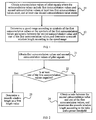
- FIG. 1 is a schematic flow chart of a method according to a first embodiment of the present invention. The method includes the following steps.
- step 11 autocorrelation values of pilot signals are obtained, where the autocorrelation values include first autocorrelation values and second autocorrelation values, at least two first autocorrelation values exist, and at least one second autocorrelation value exists.
- the pilot signal may be a CPICH signal.
- a signal autocorrelation function of the Rayleigh channel presents the characteristic of a zero-order Bessel function.
- the zero-order Bessel function is related to the Doppler frequency shift, and the Doppler frequency shift is related to a relative speed between a mobile device and a transmitting station. Therefore, in this embodiment of the present invention, speed estimation may be performed according to an autocorrelation function of the CPICH signal, so that different smooth window lengths are determined according to different speeds.
- the embodiment of the present invention is also applicable to the Rician channel.
- an antenna separation value of the CPICH signal may be used to represent the CPICH signal at a receiving end.
- a time slot index is t
- a path index is j
- an antenna separation value index is i
- an antenna separation value of the i th pilot signal in the j th path is A i,j ( t ).
- the autocorrelation value may be an autocorrelation value in non-zero correlation intervals, which refers to an autocorrelation value obtained by using the foregoing calculation formula when k ⁇ 0 . Since noise processing needs to be performed on autocorrelation values in the zero correlation interval, in this embodiment, a non-zero autocorrelation value is adopted, so that the noise processing does not need to be performed. Of course, if the autocorrelation values in the zero correlation interval are adopted as the autocorrelation values, the noise processing may be further performed, and then the principle of the embodiment of the present invention is adopted.
- a speed range is determined according to symbols of the first autocorrelation values or the symbols of the first autocorrelation values and a ratio value between the second autocorrelation value and one of the first autocorrelation values, and a smooth window length is determined according to the speed range.
- An autocorrelation function may show a degree of correlation between two signals having a time interval.
- the degree of correlation is higher, and the corresponding speed is lower. Therefore, the corresponding speed range may be determined according to the autocorrelation values. Since at different speeds the channels correspond to different optimal smooth window lengths, the smooth window length may be determined according to the speeds to obtain the optimal performance.
- the applicable speed range may be expanded when the first autocorrelation value is adopted, and the accuracy of the applicable speed range may be increased in a certain speed range when the ratio value between the second autocorrelation value and the one of first autocorrelation values is adopted.
- the autocorrelation function is obtained, the speed range is determined according to the autocorrelation function, and the smooth window length is determined according to the speed range, so that different smooth window lengths may be determined according to different speeds, thereby avoiding the problems caused by a fixed smooth window length.
- the speed range is determined according to the symbols of the autocorrelation values, so that an effective range of the speed estimation is expanded; after the approximate speed range is determined according to the symbols of the autocorrelation values, the speed range is determined according to the ratio value between autocorrelation values, so as to increase the accuracy of the speed estimation in a speed range with a higher accuracy demand.
- FIG. 2 is a schematic flow chart of a method according to a second embodiment of the present invention. The method includes the following steps.
- step 21 first autocorrelation values and second autocorrelation values of pilot signals are obtained, where two first autocorrelation values exist, and only one second autocorrelation value exists.
- An autocorrelation value is R(k).
- R(k) An autocorrelation value for the calculation formula of R(k), reference may be made to the first embodiment.
- the first autocorrelation values may be represented as R(k 1 ) and R( k 2) respectively, and the second autocorrelation value is represented as R( k 3) .
- step 22 it is determined whether at least one of the first autocorrelation values is a negative value, and if yes, step 23 is performed; otherwise, step 24 is performed.
- a smooth window length is determined as a first length value.
- a first speed range is determined, where the first speed range is an extremely high speed range, for example, a speed is higher than 150 kilometers per hour (150 km/h) and generally lower than 800 km/h.
- step 24 a ratio value between the second autocorrelation value and one of the first autocorrelation values is obtained, and the smooth window length is determined according to the ratio value and a preset threshold.
- a second speed range may be determined, where the second speed range is lower than 150 km/h (or higher than 800 km/h). Since the speed higher than 800 km/h hardly occurs in a practical application scenario, the second speed range is lower than 150 km/h by default when both R(k1) and R(k2) are positive values.
- new autocorrelation values may be further introduced, and it is determined whether the speed range is lower than 150 km/h or higher than 800 km/h according to the new autocorrelation values.
- 150 km/h is taken as an example. Under this circumstance, in order to increase the accuracy, this range needs to be further divided.
- a first threshold Threshold _1 and a second threshold Threshold _2 are set (Threshold _1 > Threshold_ 2 ), the specific values of which may be determined according to a practical situation, for example, 0.97 and 0.55 respectively.
- R k ⁇ 3 R k ⁇ 1 is taken as an example for the ratio value between the second autocorrelation value and one of the first autocorrelation values.
- the smooth window length is determined as a second length value, which may be 15. If Threshold_ 2 ⁇ R k ⁇ 3 R k ⁇ 1 ⁇ Threshold_ 1 , a medium speed channel is determined. Under this circumstance, a medium smooth window length needs to be adopted. For example, the smooth window length is determined as a third length value, which may be 10.
- the smooth window length is determined as a fourth length value, which may be 5.
- ⁇ filtering may also be performed on the ratio value, and then the comparison with the threshold is performed.
- standards corresponding to all the types of channels may be unified by using an interference elimination technology.
- the interference elimination technology is adopted so that all the types of channels correspond to approximately unified thresholds.
- symbols of the first autocorrelation values are first compared to divide a wide speed range.
- speed range is an extremely high speed range, it may be directly determined that a small smooth window length is adopted.
- speed division may be further performed to increase the accuracy.
- an effective range of speed estimation may be expanded, so as to ensure that higher accuracy of speed estimation is obtained within a lower speed range, which satisfies system requirements, so as to further increase the accuracy of the channel estimation and improve the system performance.
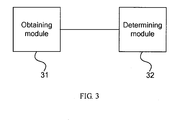
- FIG. 3 is a schematic diagram showing a structure of a device according to a third embodiment of the present invention.
- the device includes an obtaining module 31 and a determining module 32.
- the obtaining module 31 is configured to obtain autocorrelation values of pilot signals, where the autocorrelation values include first autocorrelation values and second autocorrelation values, at least two first autocorrelation values exist, and at least one second autocorrelation value exists.
- the determining module 32 is configured to determine a speed range according to symbols of the first autocorrelation values or the symbols of the first autocorrelation values and a ratio value between the second autocorrelation value and one of the first autocorrelation values and determine a smooth window length according to the speed range.
- the autocorrelation values of the pilot signals are autocorrelation values in non-zero correlation intervals.
- the first autocorrelation values may be R(k1) and R(k2)
- the second autocorrelation value is R(k3) .
- the determining module 32 may be specifically configured to determine a first speed range when either of R(k1) and R ( k 2) is a negative value and determine the smooth window length corresponding to the first speed range as a first length value; or determine a second speed range when R(k1) and R(k2) are both positive values, determine a fine range within the second speed range according to a ratio value between R(k3) and R(k1) and a preset threshold when in the second speed range, and determine the smooth window length according to the fine range, where the first length value is smaller than or equal to the smooth window length within the second speed range.
- the determining module 32 is configured to determine the smooth window length as a second length value when the ratio value between R(k3) and R(k 1 ) is greater than a first preset threshold, determine the smooth window length as a third length value when the ratio value between R(k3) and R(k 1 ) is between the first preset threshold and a second preset threshold, or determine the smooth window length as a fourth length value when the ratio value between R(k3) and R(k1) is smaller than the second preset threshold, where the second length value is greater than the third length value, the third length value is greater than the fourth length value, and the fourth length value is greater than or equal to the first length value.
- symbols of the first autocorrelation values are first compared to divide a large speed range.
- speed is in an extremely high speed range, it may be directly determined that a small smooth window length is adopted.
- speed division may be further performed to increase the accuracy.
- an effective range of speed estimation may be expanded, so as to ensure that higher accuracy of the speed estimation is obtained within a low speed range, which satisfies system requirements, thereby further increasing the accuracy of the channel estimation and improving the system performance.
- the program may be stored in a computer readable storage medium.
- the storage medium may be any medium capable of storing program codes, such as a Read Only Memory (ROM), a Random Access Memory (RAM), a magnetic disk, or an optical disk.
Landscapes
- Engineering & Computer Science (AREA)
- Power Engineering (AREA)
- Computer Networks & Wireless Communication (AREA)
- Signal Processing (AREA)
- Mobile Radio Communication Systems (AREA)
- Radar Systems Or Details Thereof (AREA)
- Synchronisation In Digital Transmission Systems (AREA)
Description
- The present invention relates to the field of mobile communications technologies, and in particular, to a method and a device for determining a smooth window length in channel estimation.
- A Wideband Code Division Multiple Access (Wideband Code Division Multiple Access, WCDMA) system adopts a Common Pilot Channel (Common Pilot Channel, CPICH) signal to perform channel estimation. During the channel estimation, a smoothing process is generally required to eliminate the influence of interferences such as noises. The principle of determining a smooth window length is that the smooth window length is as long as possible while ensuring correlation between signals within the window. If the smooth window length is too small, the correlation between signals cannot be fully utilized, so that a good noise suppression effect is unable to be achieved. If the smooth window length is too large, the smoothing operation is performed on signals with low correlation, so that the accuracy of channel estimation is decreased and throughput performance is directly affected. Therefore, proper selection of the smooth window length according to the signal correlation is one of the efficient ways to increase the accuracy of the channel estimation and improve system performance.
- A method and a system for Doppler estimation are disclosed in a published patent application, No.
2008/0056390 - user velocity is increased, the pilot symbol filtering window length is reduced, as the use velocity decreases, the pilot symbol filtering window length is increased.
- A method and a system for accurately estimating Doppler spread, are disclosed in a published international application, No.
WO 02/078213 - In wireless communications, the signal correlation may be measured by a coherence time, which is a statistical average value of time intervals in which a channel impulse response remains the same, and is approximately the reciprocal of a Doppler frequency shift. The Doppler frequency shift is mainly caused by a relative speed between a user device and a base station. The smooth window lengths in optimal channel estimation corresponding to different speeds are different.
- In the prior art, a fixed smooth window length is adopted during determination of the smooth window length, which may cause that the suppression performance gain cannot be obtained at a low speed and that the data having relatively low correlation may be introduced at a high speed, thereby causing the performance degradation.
- Embodiments of the present invention provide a method and a device for determining a smooth window length in channel estimation, so as to solve the problem caused by a fixed smooth window length in the prior art.
- An embodiment of the present invention provides a method for determining a smooth window length to eliminate the influence of interferences in channel estimation, where the method includes:
- obtaining autocorrelation values of pilot signals, where the autocorrelation values include at least two first autocorrelation values and at least one second autocorrelation values, wherein the autocorrelation values of the pilot signals are autocorrelation values in non-zero correlation intervals, and a calculation formula for obtaining the autocorrelation values of the pilot signals is as follows:

- wherein R(k) is the autocorrelation value of the pilot signal, k is a correlation interval and
- not equal to 0, M is the preset number of multi-path search periods, and Rf (k) is an autocorrelation value of a pilot signal within a multi-path search period of an index f, and the calculation formula of Rf (k) is as follows:
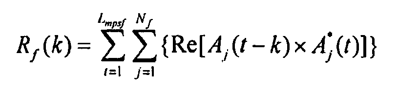
- wherein Lmpsf is the number of pilot channel time slots contained in the multi-path search period of the index f, Nf is the number of effective paths in the multi-path search period of the index f, Re() is an operation for taking a real part, A* j (t) is a conjugate function of Aj (t), Aj (t) is an accumulated value of the antenna separation values of the pilot signals within each time slot, and a calculation formula of Aj (t) is as follows:
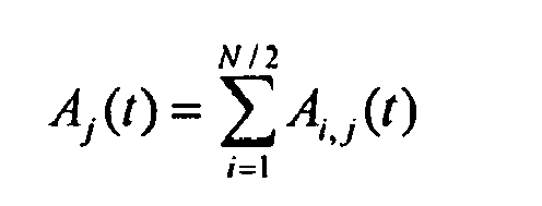
- wherein N is the number of pilot signal symbols within each time slot, Ai,j (t) is an antenna separation value of a pilot signal of an index i corresponding to a path of an index j within a time slot of an index t ; the first autocorrelation values are R(k1) and R(k2), and the second autocorrelation value is R(k3), wherein |k1| < |k2| < |k3|; and
- determining a speed range according to symbols of the first autocorrelation values or the symbols of the first autocorrelation values and a ratio value between the second autocorrelation value and one of the first autocorrelation values, and determining the smooth window length according to the speed range, wherein, the determining the speed range according to the symbols of the first autocorrelation values or the symbols of the first autocorrelation values and the ratio value between the second autocorrelation value and one of the first autocorrelation values and the determining the smooth window length according to the speed range comprise:
- when either of R(k1) and R(k2) is a negative value, determining a first speed range, and determining the smooth window length corresponding to the first speed range as a first length value, wherein, if the first speed range is a high speed range, a smaller smooth window length is adopted as the first length value; and
- when R(k1) and R(k2) are both positive values, determining a second speed range, determining a fine range within the second speed range according to a ratio value between R(k3) and R(k1) and a preset threshold when in the second speed range, and determining the smooth window length according to the fine range,
- wherein the first length value is smaller than or equal to the smooth window length within the second speed range, and the unit of the smooth window is the number of the antenna separation values Ai,j (t) of pilot signals.
- Another embodiment of the present invention provides a device for determining a smooth window length to eliminate the influence of interferences in channel estimation, where the device includes:
- an obtaining module, configured to obtain autocorrelation values of pilot signals, where the autocorrelation values include at least two first autocorrelation values and at least one second autocorrelation values; wherein the autocorrelation values of the pilot signals are autocorrelation values in non-zero correlation intervals, and the autocorrelation value of the pilot signals is as follows:

- wherein R(k) is the autocorrelation value of the pilot signal, k is a correlation interval and not equal to 0, M is the preset number of multi-path search periods, and Rf (k) is an autocorrelation value of a pilot signal within a multi-path search period of an index f, and the calculation formula of Rf (k) is as follows:

- wherein Lmpsf is the number of pilot channel time slots contained in the multi-path search period of the index f, Nf is the number of effective paths in the multi-path search period of the index f, Re() is an operation for taking a real part,


- wherein N is the number of pilot signal symbols within each time slot, Ai,j (t) is an antenna separation value of a pilot signal of an index i corresponding to a path of an index j within a time slot of an index t; the first autocorrelation values are R(k1) and R(k2), and the second autocorrelation value is R(k3) ; and
- a determining module, configured to determine a speed range according to symbols of the first autocorrelation values or the symbols of the first autocorrelation values and a ratio value between the second autocorrelation value and one of the first autocorrelation values, and determine the smooth window length according to the speed range, wherein, the determining the speed range according to the symbols of the first autocorrelation values or the symbols of the first autocorrelation values and the ratio value between the second autocorrelation value and one of the first autocorrelation values and the determining the smooth window length according to the speed range further comprises the determining module is further configured to determine a first speed range and determine the smooth window length corresponding to the first speed range as a first length value when either of R(k1) and R(k2) is a negative value, wherein, if the first speed range is a high speed range, a smaller smooth window length is adopted as the first length value; or determine a second speed range when R(k1) and R(k2) are both positive values, determine a fine range within the second speed range according to a ratio value between R(k3) and R(k1) and a preset threshold when in the second speed range, and determine the smooth window length according to the fine range, wherein the first length value is smaller than or equal to the smooth window length within the second speed range, and |k1| < |k2| < |k3|, and the unit of the window is the number of the antenna separation values Ai,j (t) of pilot signals.
- It can be seen from the technical solutions of the present invention that, through the method and the device for determining the smooth window length in the channel estimation according to the present invention, an autocorrelation function is obtained, the speed range is determined according to the autocorrelation function, and the smooth window length is determined according to the speed range, so that different smooth window lengths may be determined according to different speeds, thereby avoiding the problems caused by the fixed smooth window length.
- To illustrate the technical solutions according to the embodiments of the present invention more clearly, the accompanying drawings required for describing the embodiments are introduced briefly in the following. Apparently, the accompanying drawings in the following description are only some embodiments of the present invention; persons of ordinary skill in the art may also derive other drawings according to the accompanying drawings without any creative effort.
-
FIG. 1 is a schematic flow chart of a method according to a first embodiment of the present invention; -
FIG. 2 is a schematic flow chart of a method according to a second embodiment of the present invention; and -
FIG. 3 is a schematic diagram showing a structure of a device according to a third embodiment of the present invention. - In order to make the objectives, technical solutions, and advantages of the embodiments of the present invention clearer, the technical solutions of the embodiments of the present invention are completely and clearly described in the following with reference to the accompanying drawings. Apparently, the embodiments in the following descriptions are merely a part of the embodiments of the present invention, rather than all the embodiments of the present invention. Persons of ordinary skill in the art can derive other embodiments based on the embodiments of the present invention without creative efforts, which all fall within the scope of the present invention.
-
FIG. 1 is a schematic flow chart of a method according to a first embodiment of the present invention. The method includes the following steps. - In step 11, autocorrelation values of pilot signals are obtained, where the autocorrelation values include first autocorrelation values and second autocorrelation values, at least two first autocorrelation values exist, and at least one second autocorrelation value exists.
- The pilot signal may be a CPICH signal. As most communication channels conform to the Rayleigh channel model. A signal autocorrelation function of the Rayleigh channel presents the characteristic of a zero-order Bessel function. The zero-order Bessel function is related to the Doppler frequency shift, and the Doppler frequency shift is related to a relative speed between a mobile device and a transmitting station. Therefore, in this embodiment of the present invention, speed estimation may be performed according to an autocorrelation function of the CPICH signal, so that different smooth window lengths are determined according to different speeds. Moreover, the embodiment of the present invention is also applicable to the Rician channel.
- Since WCDMA supports dual-antenna transmission, an antenna separation value of the CPICH signal may be used to represent the CPICH signal at a receiving end.
- It is assumed that a time slot index is t, a path index is j , and an antenna separation value index is i, so in the time slot t, an antenna separation value of the ith pilot signal in the jth path is Ai,j (t).
- It is assumed that the number of effective paths within a multi-path search period of an index f is N f and the number of pilot signal symbols corresponding to each antenna is N, so an accumulated value of the antenna separation values of the pilot signals within each time slot is as follows:

- Taking N = 10 as an example, the accumulated value is

- It is assumed that the number of pilot channel time slots contained in the multi-path search period of the index f is Lmpsf , so an autocorrelation value of the antenna separation values of the pilot signals at a time slot level Rf(k) is as follows:

where f is the index of the multi-path search period. - It is assumed that the number of the multi-path search periods contained in a single speed estimation period is M, the autocorrelation value of the pilot signals within the single speed estimation period R(k) is as follows:

where k is a correlation interval, and the value of M may be 100. - Moreover, in the embodiment of the present invention, the autocorrelation value may be an autocorrelation value in non-zero correlation intervals, which refers to an autocorrelation value obtained by using the foregoing calculation formula when k ≠ 0 . Since noise processing needs to be performed on autocorrelation values in the zero correlation interval, in this embodiment, a non-zero autocorrelation value is adopted, so that the noise processing does not need to be performed. Of course, if the autocorrelation values in the zero correlation interval are adopted as the autocorrelation values, the noise processing may be further performed, and then the principle of the embodiment of the present invention is adopted.
- In
step 12, a speed range is determined according to symbols of the first autocorrelation values or the symbols of the first autocorrelation values and a ratio value between the second autocorrelation value and one of the first autocorrelation values, and a smooth window length is determined according to the speed range. - An autocorrelation function may show a degree of correlation between two signals having a time interval. When the autocorrelation value is larger, the degree of correlation is higher, and the corresponding speed is lower. Therefore, the corresponding speed range may be determined according to the autocorrelation values. Since at different speeds the channels correspond to different optimal smooth window lengths, the smooth window length may be determined according to the speeds to obtain the optimal performance.
- The applicable speed range may be expanded when the first autocorrelation value is adopted, and the accuracy of the applicable speed range may be increased in a certain speed range when the ratio value between the second autocorrelation value and the one of first autocorrelation values is adopted. In this embodiment, the autocorrelation function is obtained, the speed range is determined according to the autocorrelation function, and the smooth window length is determined according to the speed range, so that different smooth window lengths may be determined according to different speeds, thereby avoiding the problems caused by a fixed smooth window length. Moreover, in this embodiment, the speed range is determined according to the symbols of the autocorrelation values, so that an effective range of the speed estimation is expanded; after the approximate speed range is determined according to the symbols of the autocorrelation values, the speed range is determined according to the ratio value between autocorrelation values, so as to increase the accuracy of the speed estimation in a speed range with a higher accuracy demand.
-
FIG. 2 is a schematic flow chart of a method according to a second embodiment of the present invention. The method includes the following steps. - In
step 21, first autocorrelation values and second autocorrelation values of pilot signals are obtained, where two first autocorrelation values exist, and only one second autocorrelation value exists. - An autocorrelation value is R(k). For the calculation formula of R(k), reference may be made to the first embodiment.
- In this embodiment, the first autocorrelation values may be represented as R(k1) and R(k2) respectively, and the second autocorrelation value is represented as R(k3) .
- The values of k1 and k2 are close to zero, for example, k1 =1 1 and k2 = 2; and the value of k3 is far from zero, for example, k3 = 4 .
- In
step 22, it is determined whether at least one of the first autocorrelation values is a negative value, and if yes, step 23 is performed; otherwise,step 24 is performed. - In
step 23, a smooth window length is determined as a first length value. - Since at least one of R(k1) and R(k2) is a negative value, a first speed range is determined, where the first speed range is an extremely high speed range, for example, a speed is higher than 150 kilometers per hour (150 km/h) and generally lower than 800 km/h.
- Since the speed is high under this circumstance, a smaller smooth window length needs to be adopted. For example, the first length value is determined as L=5. In this embodiment of the present invention, the unit of a smooth window is the number of antenna separation values Ai,j(t) of pilot signals. For example, if L=5, it indicates that each smooth window contains five Ai,j(t) .
- In
step 24, a ratio value between the second autocorrelation value and one of the first autocorrelation values is obtained, and the smooth window length is determined according to the ratio value and a preset threshold. - Since both R(k1) and R(k2) are positive values, a second speed range may be determined, where the second speed range is lower than 150 km/h (or higher than 800 km/h). Since the speed higher than 800 km/h hardly occurs in a practical application scenario, the second speed range is lower than 150 km/h by default when both R(k1) and R(k2) are positive values. Of course, if a scenario that the speed range is higher than 800 km/h is considered, new autocorrelation values may be further introduced, and it is determined whether the speed range is lower than 150 km/h or higher than 800 km/h according to the new autocorrelation values. Here, 150 km/h is taken as an example. Under this circumstance, in order to increase the accuracy, this range needs to be further divided.
- For example, a first threshold Threshold _1 and a second threshold Threshold _2 are set (Threshold _1 > Threshold_2), the specific values of which may be determined according to a practical situation, for example, 0.97 and 0.55 respectively.

- If


- If

- It can be understood that, when calculating
- It can be understood that, in order to further improve the system performance, more autocorrelation values in different interval positions and/or more thresholds may be introduced. The time interval and/or threshold may be specifically determined according to practical requirements.
- Furthermore, for different types of channels, standards corresponding to all the types of channels may be unified by using an interference elimination technology. For example, the interference elimination technology is adopted so that all the types of channels correspond to approximately unified thresholds.
- In this embodiment, symbols of the first autocorrelation values are first compared to divide a wide speed range. When the speed range is an extremely high speed range, it may be directly determined that a small smooth window length is adopted. When the first autocorrelation values are both positive values, speed division may be further performed to increase the accuracy. In this embodiment, through the two-step method, an effective range of speed estimation may be expanded, so as to ensure that higher accuracy of speed estimation is obtained within a lower speed range, which satisfies system requirements, so as to further increase the accuracy of the channel estimation and improve the system performance.
-
FIG. 3 is a schematic diagram showing a structure of a device according to a third embodiment of the present invention. The device includes an obtainingmodule 31 and a determiningmodule 32. The obtainingmodule 31 is configured to obtain autocorrelation values of pilot signals, where the autocorrelation values include first autocorrelation values and second autocorrelation values, at least two first autocorrelation values exist, and at least one second autocorrelation value exists. The determiningmodule 32 is configured to determine a speed range according to symbols of the first autocorrelation values or the symbols of the first autocorrelation values and a ratio value between the second autocorrelation value and one of the first autocorrelation values and determine a smooth window length according to the speed range. - The autocorrelation values of the pilot signals are autocorrelation values in non-zero correlation intervals. The autocorrelation value of the pilot signal is as follows:

where R(k) is the autocorrelation value of the pilot signals, k is a correlation interval and not equal to 0, M is the preset number of multi-path search periods, Rf(k) is an autocorrelation value of a pilot signal within a multi-path search period of an index f , and a calculation formula of Rf(k) is as follows:
where Lmpsf is the number of pilot channel time slots contained in the multi-path search period of the index f , N f is the number of effective paths in the multi-path search period of the index f , Re() is an operation for taking a real part,

where N is the number of pilot signal symbols within each time slot, Ai,j(t) is an antenna separation value of a pilot signal of an index i corresponding to a path of an index j within a time slot of an index t . - Specifically, the first autocorrelation values may be R(k1) and R(k2) , and the second autocorrelation value is R(k3) .
- The determining
module 32 may be specifically configured to determine a first speed range when either of R(k1) and R(k2) is a negative value and determine the smooth window length corresponding to the first speed range as a first length value; or determine a second speed range when R(k1) and R(k2) are both positive values, determine a fine range within the second speed range according to a ratio value between R(k3) and R(k1) and a preset threshold when in the second speed range, and determine the smooth window length according to the fine range, where the first length value is smaller than or equal to the smooth window length within the second speed range. Furthermore, the determiningmodule 32 is configured to determine the smooth window length as a second length value when the ratio value between R(k3) and R(k1) is greater than a first preset threshold, determine the smooth window length as a third length value when the ratio value between R(k3) and R(k1) is between the first preset threshold and a second preset threshold, or determine the smooth window length as a fourth length value when the ratio value between R(k3) and R(k1) is smaller than the second preset threshold, where the second length value is greater than the third length value, the third length value is greater than the fourth length value, and the fourth length value is greater than or equal to the first length value. The specific length values may be k1=1, k2 = 2, and k3 = 4 . - In this embodiment, symbols of the first autocorrelation values are first compared to divide a large speed range. When the speed is in an extremely high speed range, it may be directly determined that a small smooth window length is adopted. When the first autocorrelation values are both positive values, speed division may be further performed to increase the accuracy.
- In this embodiment, through the two-step method, an effective range of speed estimation may be expanded, so as to ensure that higher accuracy of the speed estimation is obtained within a low speed range, which satisfies system requirements, thereby further increasing the accuracy of the channel estimation and improving the system performance.
- Persons of ordinary skill in the art should understand that, all or a part of the steps of the method according to the embodiments may be implemented by a program instructing relevant hardware. The program may be stored in a computer readable storage medium. When the program is executed, the steps of the method according to the embodiments are performed. The storage medium may be any medium capable of storing program codes, such as a Read Only Memory (ROM), a Random Access Memory (RAM), a magnetic disk, or an optical disk.
- Finally, it should be noted that the preceding embodiments are merely provided for describing the technical solutions of the present invention, but not intended to limit the present invention. It should be understood by persons of ordinary skill in the art that although the present invention has been described in detail with reference to the embodiments, modifications may be made to the technical solutions described in the embodiments, or replacements may be made to some technical features in the technical solutions, as long as such modifications or replacements do not depart from the scope of the claims.
Claims (7)
- A method for determining a smooth window length to eliminate the influence of interferences in channel estimation, comprising:obtaining (11) autocorrelation values of pilot signals; and characterized in thatthe autocorrelation values comprise at least two first autocorrelation values and at least one second autocorrelation value, wherein the autocorrelation values of the pilot signals are autocorrelation values in non-zero correlation intervals, and a calculation formula for obtaining the autocorrelation values of the pilot signals is as follows:
 wherein R(k) is the autocorrelation value of the pilot signal, k is a correlation interval and not equal to 0, M is the preset number of multi-path search periods, and Rf (k) is an autocorrelation value of a pilot signal within a multi-path search period of an index f, and the calculation formula of Rf (k) is as follows:
 wherein Lmpsf is the number of pilot channel time slots contained in the multi-path search period of the index f, Nf is the number of effective paths in the multi-path search period of the index f, Re() is an operation for taking a real part, A*j (t) is a conjugate function of Aj (t), Aj(t) is an accumulated value of the antenna separation values of the pilot signals within each time slot, and a calculation formula of Aj(t) is as follows:
 wherein N is the number of pilot signal symbols within each time slot, A i,j (t) is an antenna separation value of a pilot signal of an index i corresponding to a path of an index j within a time slot of an index t; the first autocorrelation values are R(k1) and R(k2), and the second autocorrelation value is R(k3), wherein |k1| < |k2| < |k3|; anddetermining (12) a speed range according to symbols of the first autocorrelation values or the symbols of the first autocorrelation values and a ratio value between the second autocorrelation value and one of the first autocorrelation values, and determining the smooth window length according to the speed range, wherein, the determining the speed range according to the symbols of the first autocorrelation values or the symbols of the first autocorrelation values and the ratio value between the second autocorrelation value and one of the first autocorrelation values and the determining the smooth window length according to the speed range comprise:when either of R(k1) and R(k2) is a negative value, determining a first speed range, and determining the smooth window length corresponding to the first speed range as a first length value, wherein, if the first speed range is a high speed range, a smaller smooth window length is adopted as the first length value; andwhen R(k1) and R(k2) are both positive values, determining a second speed range, determining a fine range within the second speed range according to a ratio value between R(k3) and R(k1) and a preset threshold when in the second speed range, and determining the smooth window length according to the fine range,wherein the first length value is smaller than or equal to the smooth window length within the second speed range, and the unit of the smooth window is the number of the antenna separation values Ai,j (t) of pilot signals.
 - The method according to claim 1, wherein the determining the fine range within the second speed range according to the ratio value between R(k3) and R(k1) and the preset threshold and determining the smooth window length according to the fine range comprise:determining the smooth window length as a second length value when the ratio value between R(k3) and R(k1) is greater than a first preset threshold;determining the smooth window length as a third length value when the ratio value between R(k3) and R(k1) is between the first preset threshold and a second preset threshold;determining the smooth window length as a fourth length value when the ratio value between R(k3) and R(k1) is smaller than the second preset threshold,wherein the second length value is greater than the third length value, the third length value is greater than the fourth length value, and the fourth length value is greater than or equal to the first length value.
- The method according to claim 2, wherein the ratio value between R(k3) and R(k1) is an α-filtered ratio value.
- The method according to any one of claims 1 to 3, wherein k1 = 1, k2 = 2, and k3 = 4.
- A device adapted or determining a smooth window length to eliminate the influence of interferences in channel estimation, comprising:an obtaining module (31), configured to obtain autocorrelation values of pilot signals; and characterized in thatthe autocorrelation values comprise at least two first autocorrelation values and at least one second autocorrelation value; wherein the autocorrelation values of the pilot signals are autocorrelation values in non-zero correlation intervals, and the autocorrelation value of the pilot signals is as follows:
 wherein R(k) is the autocorrelation value of the pilot signal, k is a correlation interval and not equal to 0, M is the preset number of multi-path search periods, and Rf (k) is an autocorrelation value of a pilot signal within a multi-path search period of an index f, and the calculation formula of Rf (k) is as follows:
 wherein Lmpsf is the number of pilot channel time slots contained in the multi-path search period of the index f, Nf is the number of effective paths in the multi-path search period of the index f, Re() is an operation for taking a real part, A*j (t) is a conjugate function of Aj (t), Aj (t) is an accumulated value of the antenna separation values of the pilot signals within each time slot, and a calculation formula of Aj (t) is as follows:
 wherein N is the number of pilot signal symbols within each time slot, Ai,j (t) is an antenna separation value of a pilot signal of an index i corresponding to a path of an index j within a time slot of an index t; the first autocorrelation values are R(k1) and R(k2), and the second autocorrelation value is R(k3) ;anda determining module (32), configured to determine a speed range according to symbols of the first autocorrelation values or the symbols of the first autocorrelation values and a ratio value between the second autocorrelation value and one of the first autocorrelation values, and determine the smooth window length according to the speed range, wherein, the determining the speed range according to the symbols of the first autocorrelation values or the symbols of the first autocorrelation values and the ratio valve between the second autocorrelation value and one of the first autocorrelation values and the determining the smooth window length according to the speed range further comprises the determining module is further configured to determine a first speed range and determine the smooth window length corresponding to the first speed range as a first length value when either of R(k1) and R(k2) is a negative value, wherein, if the first speed range is a high speed range, a smaller smooth window length is adopted as the first length value; or determine a second speed range when R(k1) and R(k2) are both positive values, determine a fine range within the second speed range according to a ratio value between R(k3) and R(k1) and a preset threshold when in the second speed range, and determine the smooth window length according to the fine range, wherein the first length value is smaller than or equal to the smooth window length within the second speed range, and |k1| < |k2| < |k3|, and the unit of the window is the number of the antenna separation values Ai,j (t) of pilot signals.
 - The device according to claim 5, wherein
the determining module is further configured to determine the smooth window length as a second length value when the ratio value between R(k3) and R(k1) is greater than a first preset threshold, determine the smooth window length as a third length value when the ratio value between R(k3) and R(k1) is between the first preset threshold and a second preset threshold, or determine the smooth window length as a fourth length value when the ratio value between R(k3) and R(k1) is smaller than the second preset threshold, wherein the second length value is greater than the third length value, the third length value is greater than the fourth length value, and the fourth length value is greater than or equal to the first length value. - The method according to any one of claims 5 and 6, wherein k1 = 1, k2 = 2, and k3 = 4.
Priority Applications (1)
| Application Number | Priority Date | Filing Date | Title |
|---|---|---|---|
| EP13171379.4A EP2640024A1 (en) | 2010-07-26 | 2011-07-25 | Method and device for determining smooth window length in channel estimation |
Applications Claiming Priority (1)
| Application Number | Priority Date | Filing Date | Title |
|---|---|---|---|
| CN 201010239269 CN101902250B (en) | 2010-07-26 | 2010-07-26 | Method and equipment for determining length of smooth window in channel estimation |
Publications (2)
| Publication Number | Publication Date |
|---|---|
| EP2413552A1 EP2413552A1 (en) | 2012-02-01 |
| EP2413552B1 true EP2413552B1 (en) | 2013-07-03 |
Family
ID=43227488
Family Applications (2)
| Application Number | Title | Priority Date | Filing Date |
|---|---|---|---|
| EP20110175203 Active EP2413552B1 (en) | 2010-07-26 | 2011-07-25 | Method and device for determining smooth window length in channel estimation |
| EP13171379.4A Withdrawn EP2640024A1 (en) | 2010-07-26 | 2011-07-25 | Method and device for determining smooth window length in channel estimation |
Family Applications After (1)
| Application Number | Title | Priority Date | Filing Date |
|---|---|---|---|
| EP13171379.4A Withdrawn EP2640024A1 (en) | 2010-07-26 | 2011-07-25 | Method and device for determining smooth window length in channel estimation |
Country Status (3)
| Country | Link |
|---|---|
| US (1) | US8780956B2 (en) |
| EP (2) | EP2413552B1 (en) |
| CN (1) | CN101902250B (en) |
Families Citing this family (4)
| Publication number | Priority date | Publication date | Assignee | Title |
|---|---|---|---|---|
| CN102571221B (en) * | 2010-12-20 | 2014-10-22 | 上海贝尔股份有限公司 | Method and equipment for estimating Doppler frequency shift in wireless communication system |
| US9081076B2 (en) | 2012-11-12 | 2015-07-14 | Isolynx, Llc | System and method for object tracking anti-jitter filtering |
| CN110531332B (en) * | 2019-07-02 | 2023-02-21 | 中国航空工业集团公司雷华电子技术研究所 | Low-altitude slow-speed small target detection method based on segmentation threshold |
| CN114757855B (en) * | 2022-06-16 | 2022-09-23 | 广州三七极耀网络科技有限公司 | Motion data correction method, device, equipment and storage medium |
Family Cites Families (5)
| Publication number | Priority date | Publication date | Assignee | Title |
|---|---|---|---|---|
| US6922452B2 (en) * | 2001-03-27 | 2005-07-26 | Telefonaktiebolaget L M Ericsson (Publ) | Method and apparatus for estimating Doppler spread |
| JP2004135247A (en) * | 2002-10-15 | 2004-04-30 | Oki Electric Ind Co Ltd | Synchronous position detecting circuit |
| US20080056390A1 (en) * | 2006-08-29 | 2008-03-06 | Motorola, Inc. | method and system for doppler estimation |
| US8199706B2 (en) * | 2006-10-27 | 2012-06-12 | Texas Instruments Incorporated | Random access design for high doppler in wireless networks |
| CN101741487B (en) * | 2010-01-19 | 2013-04-17 | 西安交通大学 | Implementation method of pilot-assisted detector for DVB-T signals in cognitive radio network |
-
2010
- 2010-07-26 CN CN 201010239269 patent/CN101902250B/en active Active
-
2011
- 2011-07-25 EP EP20110175203 patent/EP2413552B1/en active Active
- 2011-07-25 EP EP13171379.4A patent/EP2640024A1/en not_active Withdrawn
- 2011-07-26 US US13/191,151 patent/US8780956B2/en active Active
Also Published As
| Publication number | Publication date |
|---|---|
| EP2640024A1 (en) | 2013-09-18 |
| CN101902250B (en) | 2013-08-07 |
| US20120020440A1 (en) | 2012-01-26 |
| US8780956B2 (en) | 2014-07-15 |
| EP2413552A1 (en) | 2012-02-01 |
| CN101902250A (en) | 2010-12-01 |
Similar Documents
| Publication | Publication Date | Title |
|---|---|---|
| US8259865B2 (en) | Methods and apparatus for adapting channel estimation in a communication system | |
| CN101909024B (en) | Method and device for estimating maximum Doppler frequency offset | |
| US20100290570A1 (en) | Method and apparatus for channel estimation in ofdm | |
| EP1210803B1 (en) | Determination of data rate, based on power spectral density estimates | |
| US8059753B2 (en) | Adaptive channel estimator and adaptive channel estimation method | |
| US9294312B2 (en) | Apparatus and method for estimating doppler spread in mobile communication system | |
| CN102647387B (en) | The removing method of co-channel interference and device | |
| US6505053B1 (en) | Method for sinusoidal modeling and prediction of fast fading processes | |
| EP2413552B1 (en) | Method and device for determining smooth window length in channel estimation | |
| EP2905986B1 (en) | Method and device for testing moving speed of terminal | |
| KR100689418B1 (en) | Apparatus and method for delay spread estimation of multipath fading channel in wireless communication system | |
| EP2096776B1 (en) | Noise power estimation apparatus and method | |
| US20050267370A1 (en) | Velocity estimation apparatus and method | |
| CN103916342B (en) | Signal-to-noise-ratio estimation method | |
| KR20090013957A (en) | Apparatus and Method for Compensating Error Estimation of Channel Impulse Response in Orthogonal Frequency Division Multiplexing Systems | |
| US20110310945A1 (en) | Radio communication apparatus and radio communication method | |
| CN116708092B (en) | Pilot parameter design method suitable for low signal-to-noise ratio MC-CDMA systems | |
| CN109005138B (en) | OFDM signal time domain parameter estimation method based on cepstrum | |
| US20160352555A1 (en) | Fine timing | |
| US8442165B2 (en) | Method and apparatus for estimating Doppler frequency in a mobile terminal | |
| JP2004159077A (en) | Data receiving device and data receiving method | |
| KR100870671B1 (en) | Method and apparatus for estimating signal-to-interference noise ratio in wireless communication system | |
| CN109302360A (en) | Channel estimation methods and device, computer readable storage medium, terminal | |
| EP2662999A1 (en) | Receiver, reception method, and computer program | |
| CN119727959B (en) | Channel detection method, device and computer readable storage medium |
Legal Events
| Date | Code | Title | Description |
|---|---|---|---|
| 17P | Request for examination filed |
Effective date: 20110725 |
|
| AK | Designated contracting states |
Kind code of ref document: A1 Designated state(s): AL AT BE BG CH CY CZ DE DK EE ES FI FR GB GR HR HU IE IS IT LI LT LU LV MC MK MT NL NO PL PT RO RS SE SI SK SM TR |
|
| AX | Request for extension of the european patent |
Extension state: BA ME |
|
| PUAI | Public reference made under article 153(3) epc to a published international application that has entered the european phase |
Free format text: ORIGINAL CODE: 0009012 |
|
| 17Q | First examination report despatched |
Effective date: 20120322 |
|
| GRAP | Despatch of communication of intention to grant a patent |
Free format text: ORIGINAL CODE: EPIDOSNIGR1 |
|
| RIN1 | Information on inventor provided before grant (corrected) |
Inventor name: JIAO, SHURONG Inventor name: ZHANG, CHUNLING Inventor name: HUA, MENG Inventor name: WU, GENGSHI Inventor name: SUN, FENGYU |
|
| GRAS | Grant fee paid |
Free format text: ORIGINAL CODE: EPIDOSNIGR3 |
|
| GRAA | (expected) grant |
Free format text: ORIGINAL CODE: 0009210 |
|
| AK | Designated contracting states |
Kind code of ref document: B1 Designated state(s): AL AT BE BG CH CY CZ DE DK EE ES FI FR GB GR HR HU IE IS IT LI LT LU LV MC MK MT NL NO PL PT RO RS SE SI SK SM TR |
|
| REG | Reference to a national code |
Ref country code: GB Ref legal event code: FG4D |
|
| REG | Reference to a national code |
Ref country code: AT Ref legal event code: REF Ref document number: 620294 Country of ref document: AT Kind code of ref document: T Effective date: 20130715 Ref country code: CH Ref legal event code: EP |
|
| REG | Reference to a national code |
Ref country code: IE Ref legal event code: FG4D |
|
| REG | Reference to a national code |
Ref country code: DE Ref legal event code: R096 Ref document number: 602011002193 Country of ref document: DE Effective date: 20130829 |
|
| PG25 | Lapsed in a contracting state [announced via postgrant information from national office to epo] |
Ref country code: SI Free format text: LAPSE BECAUSE OF FAILURE TO SUBMIT A TRANSLATION OF THE DESCRIPTION OR TO PAY THE FEE WITHIN THE PRESCRIBED TIME-LIMIT Effective date: 20130703 |
|
| REG | Reference to a national code |
Ref country code: AT Ref legal event code: MK05 Ref document number: 620294 Country of ref document: AT Kind code of ref document: T Effective date: 20130703 |
|
| REG | Reference to a national code |
Ref country code: NL Ref legal event code: VDEP Effective date: 20130703 |
|
| REG | Reference to a national code |
Ref country code: LT Ref legal event code: MG4D |
|
| PG25 | Lapsed in a contracting state [announced via postgrant information from national office to epo] |
Ref country code: LT Free format text: LAPSE BECAUSE OF FAILURE TO SUBMIT A TRANSLATION OF THE DESCRIPTION OR TO PAY THE FEE WITHIN THE PRESCRIBED TIME-LIMIT Effective date: 20130703 Ref country code: PT Free format text: LAPSE BECAUSE OF FAILURE TO SUBMIT A TRANSLATION OF THE DESCRIPTION OR TO PAY THE FEE WITHIN THE PRESCRIBED TIME-LIMIT Effective date: 20131104 Ref country code: SE Free format text: LAPSE BECAUSE OF FAILURE TO SUBMIT A TRANSLATION OF THE DESCRIPTION OR TO PAY THE FEE WITHIN THE PRESCRIBED TIME-LIMIT Effective date: 20130703 Ref country code: NO Free format text: LAPSE BECAUSE OF FAILURE TO SUBMIT A TRANSLATION OF THE DESCRIPTION OR TO PAY THE FEE WITHIN THE PRESCRIBED TIME-LIMIT Effective date: 20131003 Ref country code: BE Free format text: LAPSE BECAUSE OF FAILURE TO SUBMIT A TRANSLATION OF THE DESCRIPTION OR TO PAY THE FEE WITHIN THE PRESCRIBED TIME-LIMIT Effective date: 20130703 Ref country code: CY Free format text: LAPSE BECAUSE OF FAILURE TO SUBMIT A TRANSLATION OF THE DESCRIPTION OR TO PAY THE FEE WITHIN THE PRESCRIBED TIME-LIMIT Effective date: 20130807 Ref country code: AT Free format text: LAPSE BECAUSE OF FAILURE TO SUBMIT A TRANSLATION OF THE DESCRIPTION OR TO PAY THE FEE WITHIN THE PRESCRIBED TIME-LIMIT Effective date: 20130703 Ref country code: HR Free format text: LAPSE BECAUSE OF FAILURE TO SUBMIT A TRANSLATION OF THE DESCRIPTION OR TO PAY THE FEE WITHIN THE PRESCRIBED TIME-LIMIT Effective date: 20130703 Ref country code: IS Free format text: LAPSE BECAUSE OF FAILURE TO SUBMIT A TRANSLATION OF THE DESCRIPTION OR TO PAY THE FEE WITHIN THE PRESCRIBED TIME-LIMIT Effective date: 20131103 |
|
| PG25 | Lapsed in a contracting state [announced via postgrant information from national office to epo] |
Ref country code: FI Free format text: LAPSE BECAUSE OF FAILURE TO SUBMIT A TRANSLATION OF THE DESCRIPTION OR TO PAY THE FEE WITHIN THE PRESCRIBED TIME-LIMIT Effective date: 20130703 Ref country code: GR Free format text: LAPSE BECAUSE OF FAILURE TO SUBMIT A TRANSLATION OF THE DESCRIPTION OR TO PAY THE FEE WITHIN THE PRESCRIBED TIME-LIMIT Effective date: 20131004 Ref country code: ES Free format text: LAPSE BECAUSE OF FAILURE TO SUBMIT A TRANSLATION OF THE DESCRIPTION OR TO PAY THE FEE WITHIN THE PRESCRIBED TIME-LIMIT Effective date: 20131014 Ref country code: LV Free format text: LAPSE BECAUSE OF FAILURE TO SUBMIT A TRANSLATION OF THE DESCRIPTION OR TO PAY THE FEE WITHIN THE PRESCRIBED TIME-LIMIT Effective date: 20130703 Ref country code: NL Free format text: LAPSE BECAUSE OF FAILURE TO SUBMIT A TRANSLATION OF THE DESCRIPTION OR TO PAY THE FEE WITHIN THE PRESCRIBED TIME-LIMIT Effective date: 20130703 Ref country code: PL Free format text: LAPSE BECAUSE OF FAILURE TO SUBMIT A TRANSLATION OF THE DESCRIPTION OR TO PAY THE FEE WITHIN THE PRESCRIBED TIME-LIMIT Effective date: 20130703 |
|
| PG25 | Lapsed in a contracting state [announced via postgrant information from national office to epo] |
Ref country code: CY Free format text: LAPSE BECAUSE OF FAILURE TO SUBMIT A TRANSLATION OF THE DESCRIPTION OR TO PAY THE FEE WITHIN THE PRESCRIBED TIME-LIMIT Effective date: 20130703 |
|
| REG | Reference to a national code |
Ref country code: IE Ref legal event code: MM4A |
|
| PG25 | Lapsed in a contracting state [announced via postgrant information from national office to epo] |
Ref country code: EE Free format text: LAPSE BECAUSE OF FAILURE TO SUBMIT A TRANSLATION OF THE DESCRIPTION OR TO PAY THE FEE WITHIN THE PRESCRIBED TIME-LIMIT Effective date: 20130703 Ref country code: MC Free format text: LAPSE BECAUSE OF FAILURE TO SUBMIT A TRANSLATION OF THE DESCRIPTION OR TO PAY THE FEE WITHIN THE PRESCRIBED TIME-LIMIT Effective date: 20130703 Ref country code: RO Free format text: LAPSE BECAUSE OF FAILURE TO SUBMIT A TRANSLATION OF THE DESCRIPTION OR TO PAY THE FEE WITHIN THE PRESCRIBED TIME-LIMIT Effective date: 20130703 Ref country code: CZ Free format text: LAPSE BECAUSE OF FAILURE TO SUBMIT A TRANSLATION OF THE DESCRIPTION OR TO PAY THE FEE WITHIN THE PRESCRIBED TIME-LIMIT Effective date: 20130703 Ref country code: DK Free format text: LAPSE BECAUSE OF FAILURE TO SUBMIT A TRANSLATION OF THE DESCRIPTION OR TO PAY THE FEE WITHIN THE PRESCRIBED TIME-LIMIT Effective date: 20130703 Ref country code: SK Free format text: LAPSE BECAUSE OF FAILURE TO SUBMIT A TRANSLATION OF THE DESCRIPTION OR TO PAY THE FEE WITHIN THE PRESCRIBED TIME-LIMIT Effective date: 20130703 |
|
| PLBE | No opposition filed within time limit |
Free format text: ORIGINAL CODE: 0009261 |
|
| STAA | Information on the status of an ep patent application or granted ep patent |
Free format text: STATUS: NO OPPOSITION FILED WITHIN TIME LIMIT |
|
| PG25 | Lapsed in a contracting state [announced via postgrant information from national office to epo] |
Ref country code: IT Free format text: LAPSE BECAUSE OF FAILURE TO SUBMIT A TRANSLATION OF THE DESCRIPTION OR TO PAY THE FEE WITHIN THE PRESCRIBED TIME-LIMIT Effective date: 20130703 |
|
| 26N | No opposition filed |
Effective date: 20140404 |
|
| REG | Reference to a national code |
Ref country code: DE Ref legal event code: R097 Ref document number: 602011002193 Country of ref document: DE Effective date: 20140404 |
|
| PG25 | Lapsed in a contracting state [announced via postgrant information from national office to epo] |
Ref country code: IE Free format text: LAPSE BECAUSE OF NON-PAYMENT OF DUE FEES Effective date: 20130725 |
|
| REG | Reference to a national code |
Ref country code: CH Ref legal event code: PL |
|
| PG25 | Lapsed in a contracting state [announced via postgrant information from national office to epo] |
Ref country code: LI Free format text: LAPSE BECAUSE OF NON-PAYMENT OF DUE FEES Effective date: 20140731 Ref country code: CH Free format text: LAPSE BECAUSE OF NON-PAYMENT OF DUE FEES Effective date: 20140731 |
|
| PG25 | Lapsed in a contracting state [announced via postgrant information from national office to epo] |
Ref country code: SM Free format text: LAPSE BECAUSE OF FAILURE TO SUBMIT A TRANSLATION OF THE DESCRIPTION OR TO PAY THE FEE WITHIN THE PRESCRIBED TIME-LIMIT Effective date: 20130703 |
|
| PG25 | Lapsed in a contracting state [announced via postgrant information from national office to epo] |
Ref country code: MT Free format text: LAPSE BECAUSE OF FAILURE TO SUBMIT A TRANSLATION OF THE DESCRIPTION OR TO PAY THE FEE WITHIN THE PRESCRIBED TIME-LIMIT Effective date: 20130703 Ref country code: TR Free format text: LAPSE BECAUSE OF FAILURE TO SUBMIT A TRANSLATION OF THE DESCRIPTION OR TO PAY THE FEE WITHIN THE PRESCRIBED TIME-LIMIT Effective date: 20130703 |
|
| PG25 | Lapsed in a contracting state [announced via postgrant information from national office to epo] |
Ref country code: HU Free format text: LAPSE BECAUSE OF FAILURE TO SUBMIT A TRANSLATION OF THE DESCRIPTION OR TO PAY THE FEE WITHIN THE PRESCRIBED TIME-LIMIT; INVALID AB INITIO Effective date: 20110725 Ref country code: RS Free format text: LAPSE BECAUSE OF FAILURE TO SUBMIT A TRANSLATION OF THE DESCRIPTION OR TO PAY THE FEE WITHIN THE PRESCRIBED TIME-LIMIT Effective date: 20131003 Ref country code: MK Free format text: LAPSE BECAUSE OF FAILURE TO SUBMIT A TRANSLATION OF THE DESCRIPTION OR TO PAY THE FEE WITHIN THE PRESCRIBED TIME-LIMIT Effective date: 20130703 Ref country code: LU Free format text: LAPSE BECAUSE OF NON-PAYMENT OF DUE FEES Effective date: 20130725 Ref country code: BG Free format text: LAPSE BECAUSE OF FAILURE TO SUBMIT A TRANSLATION OF THE DESCRIPTION OR TO PAY THE FEE WITHIN THE PRESCRIBED TIME-LIMIT Effective date: 20130703 |
|
| REG | Reference to a national code |
Ref country code: FR Ref legal event code: PLFP Year of fee payment: 6 |
|
| REG | Reference to a national code |
Ref country code: FR Ref legal event code: PLFP Year of fee payment: 7 |
|
| REG | Reference to a national code |
Ref country code: FR Ref legal event code: PLFP Year of fee payment: 8 |
|
| PG25 | Lapsed in a contracting state [announced via postgrant information from national office to epo] |
Ref country code: AL Free format text: LAPSE BECAUSE OF FAILURE TO SUBMIT A TRANSLATION OF THE DESCRIPTION OR TO PAY THE FEE WITHIN THE PRESCRIBED TIME-LIMIT Effective date: 20130703 |
|
| REG | Reference to a national code |
Ref country code: DE Ref legal event code: R081 Ref document number: 602011002193 Country of ref document: DE Owner name: HUAWEI DEVICE CO., LTD., DONGGUAN, CN Free format text: FORMER OWNER: HUAWEI DEVICE CO., LTD., SHENZHEN, GUANGDONG, CN Ref country code: DE Ref legal event code: R081 Ref document number: 602011002193 Country of ref document: DE Owner name: HONOR DEVICE CO., LTD., SHENZHEN, CN Free format text: FORMER OWNER: HUAWEI DEVICE CO., LTD., SHENZHEN, GUANGDONG, CN |
|
| REG | Reference to a national code |
Ref country code: GB Ref legal event code: 732E Free format text: REGISTERED BETWEEN 20190124 AND 20190130 |
|
| REG | Reference to a national code |
Ref country code: DE Ref legal event code: R081 Ref document number: 602011002193 Country of ref document: DE Owner name: HONOR DEVICE CO., LTD., SHENZHEN, CN Free format text: FORMER OWNER: HUAWEI DEVICE CO., LTD., DONGGUAN, GUANGDONG, CN |
|
| REG | Reference to a national code |
Ref country code: GB Ref legal event code: 732E Free format text: REGISTERED BETWEEN 20210624 AND 20210630 |
|
| PGFP | Annual fee paid to national office [announced via postgrant information from national office to epo] |
Ref country code: GB Payment date: 20250605 Year of fee payment: 15 |
|
| PGFP | Annual fee paid to national office [announced via postgrant information from national office to epo] |
Ref country code: FR Payment date: 20250610 Year of fee payment: 15 |
|
| PGFP | Annual fee paid to national office [announced via postgrant information from national office to epo] |
Ref country code: DE Payment date: 20250604 Year of fee payment: 15 |