EP2413514A1 - Radio communication apparatus and radio communication method - Google Patents
Radio communication apparatus and radio communication method Download PDFInfo
- Publication number
- EP2413514A1 EP2413514A1 EP11175346A EP11175346A EP2413514A1 EP 2413514 A1 EP2413514 A1 EP 2413514A1 EP 11175346 A EP11175346 A EP 11175346A EP 11175346 A EP11175346 A EP 11175346A EP 2413514 A1 EP2413514 A1 EP 2413514A1
- Authority
- EP
- European Patent Office
- Prior art keywords
- mobile terminal
- apparatuses
- radio communication
- scheduling
- terminal apparatus
- Prior art date
- Legal status (The legal status is an assumption and is not a legal conclusion. Google has not performed a legal analysis and makes no representation as to the accuracy of the status listed.)
- Granted
Links
Images


Classifications
-
- H—ELECTRICITY
- H04—ELECTRIC COMMUNICATION TECHNIQUE
- H04B—TRANSMISSION
- H04B7/00—Radio transmission systems, i.e. using radiation field
- H04B7/02—Diversity systems; Multi-antenna system, i.e. transmission or reception using multiple antennas
- H04B7/022—Site diversity; Macro-diversity
- H04B7/024—Co-operative use of antennas of several sites, e.g. in co-ordinated multipoint or co-operative multiple-input multiple-output [MIMO] systems
-
- H—ELECTRICITY
- H04—ELECTRIC COMMUNICATION TECHNIQUE
- H04B—TRANSMISSION
- H04B7/00—Radio transmission systems, i.e. using radiation field
- H04B7/02—Diversity systems; Multi-antenna system, i.e. transmission or reception using multiple antennas
- H04B7/04—Diversity systems; Multi-antenna system, i.e. transmission or reception using multiple antennas using two or more spaced independent antennas
- H04B7/0413—MIMO systems
- H04B7/0452—Multi-user MIMO systems
-
- H—ELECTRICITY
- H04—ELECTRIC COMMUNICATION TECHNIQUE
- H04B—TRANSMISSION
- H04B7/00—Radio transmission systems, i.e. using radiation field
- H04B7/02—Diversity systems; Multi-antenna system, i.e. transmission or reception using multiple antennas
- H04B7/04—Diversity systems; Multi-antenna system, i.e. transmission or reception using multiple antennas using two or more spaced independent antennas
- H04B7/06—Diversity systems; Multi-antenna system, i.e. transmission or reception using multiple antennas using two or more spaced independent antennas at the transmitting station
- H04B7/0613—Diversity systems; Multi-antenna system, i.e. transmission or reception using multiple antennas using two or more spaced independent antennas at the transmitting station using simultaneous transmission
- H04B7/0615—Diversity systems; Multi-antenna system, i.e. transmission or reception using multiple antennas using two or more spaced independent antennas at the transmitting station using simultaneous transmission of weighted versions of same signal
- H04B7/0619—Diversity systems; Multi-antenna system, i.e. transmission or reception using multiple antennas using two or more spaced independent antennas at the transmitting station using simultaneous transmission of weighted versions of same signal using feedback from receiving side
- H04B7/0621—Feedback content
- H04B7/0628—Diversity capabilities
-
- H—ELECTRICITY
- H04—ELECTRIC COMMUNICATION TECHNIQUE
- H04B—TRANSMISSION
- H04B7/00—Radio transmission systems, i.e. using radiation field
- H04B7/02—Diversity systems; Multi-antenna system, i.e. transmission or reception using multiple antennas
- H04B7/04—Diversity systems; Multi-antenna system, i.e. transmission or reception using multiple antennas using two or more spaced independent antennas
- H04B7/06—Diversity systems; Multi-antenna system, i.e. transmission or reception using multiple antennas using two or more spaced independent antennas at the transmitting station
- H04B7/0613—Diversity systems; Multi-antenna system, i.e. transmission or reception using multiple antennas using two or more spaced independent antennas at the transmitting station using simultaneous transmission
- H04B7/0615—Diversity systems; Multi-antenna system, i.e. transmission or reception using multiple antennas using two or more spaced independent antennas at the transmitting station using simultaneous transmission of weighted versions of same signal
- H04B7/0619—Diversity systems; Multi-antenna system, i.e. transmission or reception using multiple antennas using two or more spaced independent antennas at the transmitting station using simultaneous transmission of weighted versions of same signal using feedback from receiving side
- H04B7/0621—Feedback content
- H04B7/063—Parameters other than those covered in groups H04B7/0623 - H04B7/0634, e.g. channel matrix rank or transmit mode selection
Definitions
- the present invention relates to a radio communication apparatus and radio communication method concerning downlink CoMP transmission (Coordinated Multiple Point transmission).
- LTE Long Term Evolution
- TR25.912 V7.1.0
- Feasibility study f or EvolvedUTRAandUTRAN Sept. 2006
- 3GPP 3 rd Generation Partnership Project
- OFDMA Orthogonal Frequency Division Multiple Access
- UE User Equipment
- OFDMA Orthogonal Frequency Division Multiple Access
- the LTE cellular system is based on frequency reuse one, large interference is received from surrounding cells and the interference level at a UE located in a cell edge is particularly high. Measures against inter-cell interference are required to compensate for such peripheral cell interference and maintain constant receiving quality.
- LTE-A LTE-Advanced
- LTE-Advanced LTE-Advanced
- eNode B independent eNB
- RRE Remote Radio Equipment
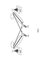
- data and reference signals are simultaneously transmitted, for example, on downlinks from a plurality of (here, two) radio base station apparatuses eNB#1 and eNB#2 to mobile terminal apparatuses UE#1 and UE#2 as shown in FIG. 1 .
- channel information (CSI: Channel State Information) is fed back from the mobile terminal apparatus UE to the radio base station apparatus eNB.
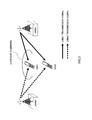
- Downlink CoMP transmission can be roughly divided into two categories; CS/CB (Coordinated Scheduling/Coordinated Beamforming) shown in FIG. 2 and JP (Joint Processing) shown in FIG. 3 .
- CS/CB Coordinatd Scheduling/Coordinated Beamforming
- JP Job Processing
- transmission is performed simultaneously for a specific UE (UE#1 or UE#2) from a plurality of cells (eNB#1, eNB#2) using the same time and frequency radio resources (joint transmission).
- precoding is performed between cells and signals are in-phase combined at a receiving point (coherent combining).
- CS/CB or JP a CSI measured value for each user is fed back to the radio base station apparatus.
- making the most of the effect of CoMP requires spatial information of the channel to be fed back accurately from the mobile terminal apparatus. This causes the amount of feedback information from the mobile terminal apparatus to the radio base station apparatus to increase.
- feedback information or data needs to be shared between the radio base station apparatuses via the X2 interface, which results in a problem that a large capacity X2 interface will be required when causing many radio base station apparatuses to coordinate with each other.
- the present invention has been implemented in view of the above problems and it is an object of the present invention to provide a radio communication apparatus and radio communication method that coordinates a plurality of radio base station apparatuses in consideration of interference cancelling capability of mobile terminal apparatuses and can thereby improve the throughput of the entire system even when the amount of information shared among the plurality of radio base station apparatuses is small.
- a radio communication apparatus is a radio communication apparatus in a system that performs multicell coordinated transmission in downlink, including a selecting section configured to select a set of mobile terminal apparatuses whose interference can be cancelled from a plurality of mobile terminal apparatus when a plurality of radio base station apparatuses perform joint scheduling using interference cancelling capability information fed back from each mobile terminal apparatus and a scheduling section configured to perform joint scheduling for the set of mobile terminal apparatuses.
- a radio communication method is a radio communication method in a system that performs multicell coordinated transmission in downlink, including a step of selecting a set of mobile terminal apparatuses whose interference can be cancelled from a plurality of mobile terminal apparatus when a plurality of radio base station apparatuses perform joint scheduling using interference cancelling capability information fed back from each mobile terminal apparatus and a step of performing joint scheduling for the set of selected mobile terminal apparatuses.
- the aforementioned inter-eNB coordination technique can avoid interference between coordinating radio base station apparatuses, but interference cancelling capability on the mobile terminal apparatus side is not considered. Since a channel measurement result of the downlink is fed back to the mobile terminal apparatus, if the mobile terminal apparatus side has interference cancelling capability, the mobile terminal apparatus side preferably cancels interference. For this reason, an inter-cell interference control (ICIC) technique making full use of the capability of the mobile terminal apparatus side becomes important.
- ICIC inter-cell interference control
- the network side assists scheduling between radio base station apparatuses and the mobile terminal apparatuses actually cancel interference.
- the network side performs scheduling between the radio base station apparatuses based on the capability of the mobile terminal apparatus, it is possible to reduce information fed back from the mobile terminal apparatus to the radio base station apparatus and also reduce information shared between the radio base station apparatuses. This makes it possible to realize coordination between base stations without the necessity of introducing a large capacity X2 interface and improve the throughput of the entire system.
- the essence of the present invention is to use, in a system that performs multicell coordinated transmission in downlink, interference cancelling capability information fed back from each mobile terminal apparatus, select a set of mobile terminal apparatuses whose interference can be cancelled from, when a plurality of radio base station apparatuses perform joint scheduling, among the mobile terminal apparatuses that have fed back the interference cancelling capability information and perform joint scheduling for the selected set of mobile terminal apparatuses and thereby improve the throughput of the entire system.
- the capability of the mobile terminal apparatus to be considered when performing scheduling between the radio base station apparatuses will be described.
- Examples of the capability of a mobile terminal apparatus may include the number of antennas and degree of delay tolerance or the like.
- the number of antennas installable on a mobile terminal apparatus varies. Many antennas are arranged on a mobile terminal apparatus requiring a high data rate. Therefore, the mobile terminal apparatus including many antennas has high space degrees of freedom and it is possible to cancel interference from other cells taking advantage of these space degrees of freedom. That is, a mobile terminal apparatus including many antennas is a mobile terminal apparatus with high space degrees of freedom (spatial interference cancelling capability).
- the tolerable delay varies depending on the application of a mobile terminal apparatus.
- An application that allows a long delay results in having a high time degrees of freedom and it is possible to cancel interference from other cells taking advantage of the time degrees of freedom. That is, a mobile terminal apparatus that tolerates a long delay is a mobile terminal apparatus having high time degrees of freedom (time interference cancelling capability).
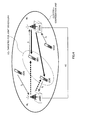
- FIG. 4 is a diagram illustrating coordinated transmission between base stations according to the embodiment of the present invention.
- radio base station apparatuses eNB#1 and eNB#2 constitute a coordination unit (cluster) for performing multicell coordinated transmission in downlink.
- Mobile terminal apparatuses UE#1, UE#2, UE#3 and UE#4 are present within this coordination unit.
- interference cancelling capability information Z of each mobile terminal apparatus UE#1 to UE#4 is fed back from each mobile terminal apparatus to the radio base station apparatus eNB#1 or eNB#2 which is the connection destination.
- the interference cancelling capability information Z i may be dynamically fed back or quasi-statically fed back.
- interference cancelling capability information Z 1 to Z 4 and information of the number of streams transmitted to each mobile terminal apparatus are shared and centralized at the radio base station apparatuses eNB#1 and eNB#2 or node such as a central station.
- the radio communication apparatus which has centralized the information searches or selects a set of mobile terminal apparatuses targeted for joint scheduling. That is, any one of the radio base station apparatuses eNB#1 and eNB#2 or a node such as the central station selects a set of mobile terminal apparatuses targeted for joint scheduling (joint scheduling target) from among the mobile terminal apparatuses UE#1 to UE#4 which fed back the interference cancelling capability information Z 1 to Z 4 .
- the mobile terminal apparatuses UE#1 and UE#2 are selected as a set of mobile terminal apparatuses.
- a set of mobile terminal apparatuses is selected within a range that does not exceed the degrees of freedom of each mobile terminal apparatus UE#1, UE#2 targeted for joint scheduling (range within which the receiving side can cancel interference even when scheduling is performed simultaneously).
- any one of the radio base station apparatuses eNB#1 and eNB#2 or node such as a central station performs joint scheduling for the set of mobile terminal apparatuses.
- Z i N i to be a space degree of freedom (e.g., the number of uncorrelated antennas or the number of independent eigenmodes)
- UE#m is connected to the eNB#1 and the UE#n is connected to the eNB#2
- their respective mobile terminal apparatus sides can separate a desired signal from an interference signal. Therefore, a set of mobile terminal apparatuses (m, n) that satisfy a condition of M 1,m +M 2,n ⁇ min(Z m , Z n ) is searched and joint scheduling is performed.
- M 1,m is the number of independent substreams to be sent from the eNB#1 to the UE#m during MIMO (Multiple Input Multiple Output) transmission and M 2,n is the number of independent substreams to be sent from the eNB#2 to the UE#n during MIMO transmission.
- MIMO Multiple Input Multiple Output
- M 1,m is the number of independent substreams to be sent from the eNB#1 to the UE#m during MIMO (Multiple Input Multiple Output) transmission
- M 2,n is the number of independent substreams to be sent from the eNB#2 to the UE#n during MIMO transmission.
- floor (x) is a floor function that returns the largest integer which is smaller than x.
- T i the space degrees of freedom on the i th mobile terminal apparatus side
- T re the time necessary for retransmission (packet retransmission)
- a channel of a mobile terminal apparatus is uncorrelated among packets
- a set of mobile terminal apparatuses (m, n) that satisfies a condition of M 1,m +M 2,n ⁇ min(k m xN m ,k n xN n ) is searched and joint scheduling is performed.
- the present invention can perform inter-cell interference control taking advantage of the interference cancelling capability of the mobile terminal apparatus.
- a mobile terminal apparatus having a high time degree of freedom and/or space degree of freedom (high interference cancelling capability) is selected for at least one of mobile terminal apparatuses targeted for joint scheduling, spatial inter-cell interference control is possible even when the mobile terminal apparatus is paired with another mobile terminal apparatus.
- the interference cancelling capability needs only to be fed back once from the mobile terminal apparatus and need not be fed back in RB (Resource Block) units as in the case of CSI information.
- RB Resource Block
- the network side need not cancel or control interference through precoding or the like. For this reason, it is possible to reduce information necessary to cancel or control interference, that is, information shared between radio base stations eNB via the X2 interface. As a result, the throughput of the entire system can be improved through coordinated transmission between base stations.
- the present invention may select the set of mobile terminal apparatuses according to other scheduling references.
- the other scheduling references include proportional fairness and sum rate maximization.
- the present invention may change the coordination unit of multicell coordinated transmission in downlink depending on whether the set of mobile terminal apparatuses is present or not.
- the coordination unit (cluster size) is reduced. Dynamically changing the coordination unit in this way enables the cluster sizeto be made variable.
- the coordination unit (cluster size) can be identified by the number of radio base station apparatuses targeted for joint scheduling.
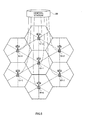
- FIG. 5 is a diagram illustrating a radio communication system including the radio communication apparatuses according to the embodiment of the present invention.
- the radio communication system includes a plurality of cells employing an independent eNB configuration as shown in FIG. 5 .
- mobile terminal apparatuses UE are accommodated under the control of radio base station apparatuses eNB 10-1 to 10-7 respectively.
- eNBs 10-1 to 10-7 of the respective cells are connected to a central station 20 which is a radio communication apparatus.
- the central station 20 centralizes interference cancelling capability information sent from each mobile terminal apparatus, selects a set of mobile terminal apparatuses whose interference can be cancelled on the receiving side even when a plurality of radio base station apparatuses perform scheduling simultaneously from among mobile terminal apparatuses that fed back the interference cancelling capability information and performs scheduling for the selected set of mobile terminal apparatuses.
- the present invention is not limited to this, but one radio base station apparatus may have the above-described function.
- This radio communication system is a system to which, for example, E-UTRA (Evolved UTRA and UTRAN) is applied.
- E-UTRA Evolved UTRA and UTRAN
- OFDM orthogonal frequency division multiple access
- SC-FDMA single carrier frequency division multiple access
- OFDM is a multicarrier transmission scheme for carrying out communication by dividing a frequency band into a plurality of narrow frequency bands (subcarriers) and mapping data to each subcarrier.
- SC-FDMA is a single carrier transmission scheme for reducing interference between mobile terminal apparatuses by dividing a frequency band into portions corresponding to the respective terminals and the plurality of mobile terminal apparatuses using different frequency bands.
- a traffic channel in E-UTRA will be described.
- physical downlink shared channel (PDSCH) and physical downlink control channel (PDCCH) shared between mobile terminal apparatuses are used.
- the physical downlink control channel is also called “downlink L1/L2 control channel.”
- User data that is, an ordinary data signal is transmitted through the above-described physical downlink shared channel.
- downlink scheduling information DL Scheduling Information
- delivery acknowledgement information ACK/NACK
- uplink scheduling grant UL Scheduling Grant
- TPC command Transmission Power Control Command
- the downlink scheduling information includes, for example, an ID of a user who carries out communication using a physical downlink shared channel, information of the transport format of the user data, that is, information of data size, modulation scheme, retransmission control (HARQ: Hybrid ARQ) and allocation information of downlink resource blocks or the like.
- information of the transport format of the user data that is, information of data size, modulation scheme, retransmission control (HARQ: Hybrid ARQ) and allocation information of downlink resource blocks or the like.
- Physical uplink shared channel (PUSCH) and physical uplink control channel (PUCCH) shared by the respective mobile terminal apparatuses are used for uplinks.
- User data that is, an ordinary data signal is transmitted through the above-described physical uplink shared channel.
- downlink channel quality information (CQI: Channel Quality Indicator) to be used for scheduling processing and adaptive modulation/demodulation and coding processing (AMC:Adaptive Modulation and Coding scheme) for a shared physical channel in downlink, delivery acknowledgement information of a physical downlink shared channel and feedback (feedback index or the like) of channel information necessary for MIMO precoding transmission are transmitted through the physical uplink control channel.
- CQI Channel Quality Indicator
- AMC adaptive Modulation and Coding scheme
- the connected base station is fed back information of the interference cancelling capability on the mobile terminal side in addition to feedback information necessary for MIMO precoding transmission, less feedback information is required for coordination compared to a system in which base stations are coordinated through precoding of a plurality of base stations so that the transmitting side avoids interference.
- FIG. 6 is a diagram illustrating a configuration of the central station in the radio communication system shown in Fig. 5 .
- a central station 20 shown in FIG. 6 is mainly constructed of a communication control section 201, an interference cancelling capability information receiving section 202, a terminal set selection section 203 and a scheduler 204.
- the communication control section 201 controls transmission/reception of data and information between the radio base station apparatuses eNB 10-1 to 10-7.
- the interference cancelling capability information receiving section 202 receives (or centralizes), from the radio base station apparatuses eNB 10-1 to 10-7, interference cancelling capability information fed back to the radio base station apparatuses eNB 10-1 to 10-7 from the respective mobile terminal apparatuses and outputs interference cancelling capability information to the terminal set selection section 203.
- the terminal set selection section 203 selects a set of mobile terminal apparatuses whose interference can be cancelled on the receiving side (mobile terminal apparatus side) even when a plurality of radio base station apparatuses perform scheduling simultaneously from among the mobile terminal apparatuses that feed back the interference cancelling capability information based on the interference cancelling capability information fed back from each mobile terminal apparatus.
- the terminal set is selected using the time degrees of freedom and/or space degrees of freedom (terminal capability) as described above.
- the terminal set selection section 203 outputs information of the selected terminal set to the scheduler 204.
- the scheduler 204 performs scheduling for the selected terminal set. That is, the scheduler 204 performs joint scheduling so as to realize the technique of coordination between base stations using autonomous distributed control (coordination between base stations) based on an independent base station configuration.
- the scheduler 204 outputs the scheduling information to a selected radio base station apparatus.
- the central station or one radio base station apparatus sets the number of radio base stations (cluster size) that perform joint scheduling beforehand (ST11). This identifies the unit of coordination between base stations.
- Each mobile terminal apparatus UE feeds back interference cancelling capability thereof to its serving radio base station apparatus eNB (ST12).
- the central station (joint scheduling node) then centralizes the interference cancelling capability information fed back in this way (ST13) .
- the terminal set selection section 203 of the central station searches a terminal set that satisfies a joint scheduling condition (ST14) and judges whether the terminal set is present or not (ST15).
- the "joint scheduling condition” is a condition that does not exceed the mutual interference cancelling capabilities when the mutual degrees of freedom of the mobile terminal apparatuses are taken into consideration, that is, a condition under which interference can be cancelled on the receiving side even when a plurality of radio base station apparatuses perform scheduling simultaneously.
- the terminal set selection section 203 selects the terminal set.
- the scheduler 204 then outputs scheduling information so that joint scheduling is performed for the selected terminal set (ST16). If necessary, the scheduler 204 checks additional scheduling criteria before performing joint scheduling using all the scheduling criteria as required. On the other hand, if no desired terminal set is found, the scheduler 204 outputs scheduling information so that single user scheduling is performed for each mobile terminal apparatus separately (ST17).
- the interference cancelling capability needs only to be fed back once from the mobile terminal apparatus and need not be fed back in RB units as in the case of CSI information.
- the network side does not need to cancel or control interference.
- information necessary to cancel or control interference that is, information shared between the radio base station apparatuses via the X2 interface.
- the throughput of the entire system can be improved with less feedback/sharing information during downlink coordinated transmission between base stations.
- the central station or one radio base station apparatus eNB sets the number of radio base station apparatuses (clustersize) thatperformjoint scheduling beforehand (ST21). This identifies the unit of coordination between the base stations.
- Each mobile terminal apparatus UE feeds back the interference cancelling capability thereof to its serving radio base station apparatus eNB (ST22).
- the central station (joint scheduling node) centralizes the interference cancelling capability information fed back in this way (ST23).
- the terminal set selection section 203 of the central station searches a terminal set that satisfies a joint scheduling condition (ST24) and judges whether the terminal set is present or not (ST25).
- the "joint scheduling condition” is a condition that does not exceed the mutual interference cancelling capabilities when the mutual degrees of freedom of the mobile terminal apparatuses are taken into consideration, that is, a condition under which interference can be cancelled on the receiving side even when a plurality of radio base station apparatuses perform scheduling simultaneously.
- the terminal set selection section 203 selects the terminal set.
- the scheduler 204 outputs scheduling information so that joint scheduling is performed for the selected terminal set (ST26). If necessary, the scheduler 204 checks additional scheduling criteriabefore performing scheduling using all scheduling criteria as required. On the other hand, if no desired terminal set is found, the central station or one radio base station apparatus eNB resets the number of radio base station apparatuses targeted for joint scheduling (cluster size) A (ST27). For example, the cluster size is reduced (A ⁇ A-1).
- the interference cancelling capability needs only to be fed back once from the mobile terminal apparatus and a large amount of information need not be fed back as in the case of CSI information.
- the network side need not cancel or control interference.
- information necessary to cancel or control interference that is, information shared between the radio base station apparatuses via the X2 interface.
- the throughput of the entire system can be improved during coordinated transmission between base stations.
- the cluster size can be dynamically changed and the cluster size can thereby be adjusted so that interference can be cancelled in the mobile terminal apparatus targeted for joint scheduling according to the interference cancelling capability of the mobile terminal apparatus connected.
- the present invention is not limited to the above embodiment, but can be implemented with various changes. Although a case has been described in the above embodiment where there are two radio base station apparatuses and four mobile terminal apparatuses, the present invention is not limited to this, but is also applicable to cases where there are other numbers of radio base station apparatuses and mobile terminal apparatuses. Furthermore, the technique of the present invention can be implemented in combination with existing inter-cell interference control techniques as appropriate. Furthermore, the present invention can be implemented by changing the number of processing sections and processing procedure in the above description as appropriate without departing from the scope of the present invention. Furthermore, each element illustrated shows a function and each function block may be implemented by hardware or software. In addition, the present invention can be implemented with changes as appropriate without departing from the scope of the present invention.
Abstract
Description
- This application is based upon and claims the benefit of priority from the prior Japanese Patent Application No.
2010-167700, filed on July 27, 2010 - The present invention relates to a radio communication apparatus and radio communication method concerning downlink CoMP transmission (Coordinated Multiple Point transmission).
- An LTE (Long Term Evolution) system (3GPP, TR25.912 (V7.1.0), "Feasibility study f or EvolvedUTRAandUTRAN", Sept. 2006) defined in 3GPP (3rd Generation Partnership Project) adopts OFDMA (Orthogonal Frequency Division Multiple Access) for downlinks. Thus, through scheduling by a radio base station apparatus, certain frequency and time radio resources are basically allocated to one mobile terminal apparatus (UE: User Equipment), and therefore users in the same cell are orthogonal to each other in the frequency and time domains. However, since the LTE cellular system is based on frequency reuse one, large interference is received from surrounding cells and the interference level at a UE located in a cell edge is particularly high. Measures against inter-cell interference are required to compensate for such peripheral cell interference and maintain constant receiving quality.
- 3GPP is studying an LTE-A (LTE-Advanced) system to realize high-speed transmission with broader coverage than the LTE cellular system. The LTE-A (LTE-Advanced) system adopts a coordinated multiple point transmission/reception (CoMP) technique as an additional inter-cell interference control (ICIC). There are two methods for realizing the CoMP technique; autonomous distributed control based on an independent eNB (eNode B) configuration (inter-eNB coordination) and concentrated control based on a remote base station (RRE: Remote Radio Equipment) configuration (intra-eNB coordination). The independent eNB configuration requires signaling through a wired transmission path (X2 interface) between eNBs as shown in
FIG. 1 . - In an inter-base-station coordinated transmission system such as CoMP, data and reference signals (RS) are simultaneously transmitted, for example, on downlinks from a plurality of (here, two) radio base station apparatuses eNB#1 and eNB#2 to mobile terminal apparatuses UE#1 and UE#2 as shown in
FIG. 1 . Furthermore, channel information (CSI: Channel State Information) is fed back from the mobile terminal apparatus UE to the radio base station apparatus eNB. - Downlink CoMP transmission can be roughly divided into two categories; CS/CB (Coordinated Scheduling/Coordinated Beamforming) shown in
FIG. 2 and JP (Joint Processing) shown inFIG. 3 . With CS/CB as shown inFIG. 2 , data is transmitted to a specific UE (UE#1) from one cell (eNB#2) in a subframe, and beam forming and scheduling coordinated among a plurality of cells are performed so as to reduce interference with the other UE (eNB##1) in the other cell. On the other hand, with JP as shown inFIG. 3 , transmission is performed simultaneously for a specific UE (UE#1 or UE#2) from a plurality of cells (eNB#1, eNB#2) using the same time and frequency radio resources (joint transmission). In this case, precoding is performed between cells and signals are in-phase combined at a receiving point (coherent combining). - With CS/CB or JP, a CSI measured value for each user is fed back to the radio base station apparatus. In this case, making the most of the effect of CoMP (avoidance of spatial interference between cells) requires spatial information of the channel to be fed back accurately from the mobile terminal apparatus. This causes the amount of feedback information from the mobile terminal apparatus to the radio base station apparatus to increase. Furthermore, in the case of coordinated transmission between a plurality of base stations as shown in
FIG. 1 , feedback information or data needs to be shared between the radio base station apparatuses via the X2 interface, which results in a problem that a large capacity X2 interface will be required when causing many radio base station apparatuses to coordinate with each other. - The present invention has been implemented in view of the above problems and it is an object of the present invention to provide a radio communication apparatus and radio communication method that coordinates a plurality of radio base station apparatuses in consideration of interference cancelling capability of mobile terminal apparatuses and can thereby improve the throughput of the entire system even when the amount of information shared among the plurality of radio base station apparatuses is small.
- A radio communication apparatus according to the present invention is a radio communication apparatus in a system that performs multicell coordinated transmission in downlink, including a selecting section configured to select a set of mobile terminal apparatuses whose interference can be cancelled from a plurality of mobile terminal apparatus when a plurality of radio base station apparatuses perform joint scheduling using interference cancelling capability information fed back from each mobile terminal apparatus and a scheduling section configured to perform joint scheduling for the set of mobile terminal apparatuses.
- A radio communication method according to the present invention is a radio communication method in a system that performs multicell coordinated transmission in downlink, including a step of selecting a set of mobile terminal apparatuses whose interference can be cancelled from a plurality of mobile terminal apparatus when a plurality of radio base station apparatuses perform joint scheduling using interference cancelling capability information fed back from each mobile terminal apparatus and a step of performing joint scheduling for the set of selected mobile terminal apparatuses.
-
-
FIG.1 is a diagram illustrating downlink coordinated transmission between base stations; -
FIG .2 is a diagram illustrating downlink coordinated transmission between base stations; -
FIG .3 is a diagram illustrating downlink coordinated transmission between base stations; -
FIG .4 is a diagram illustrating downlink coordinated transmission between base stations according to the present embodiment; -
FIG .5 is a diagram illustrating a radio communication system performing a radio communication method according to the present embodiment; -
FIG. 6 is a diagram illustrating a configuration of a radio communication apparatus in the radio communication system shown inFIG.5 ; -
FIG. 7 is a flowchart for illustrating the radio communication method according to the present embodiment; and -
FIG. 8 is a flowchart for illustrating another example of the radio communication method according to the present embodiment. - Hereinafter, an embodiment of the present invention will be described in detail with reference to the accompanying drawings.
The aforementioned inter-eNB coordination technique can avoid interference between coordinating radio base station apparatuses, but interference cancelling capability on the mobile terminal apparatus side is not considered. Since a channel measurement result of the downlink is fed back to the mobile terminal apparatus, if the mobile terminal apparatus side has interference cancelling capability, the mobile terminal apparatus side preferably cancels interference. For this reason, an inter-cell interference control (ICIC) technique making full use of the capability of the mobile terminal apparatus side becomes important. - The inventors noticed the inter-cell interference control technique making use of the capability of the mobile terminal apparatus side, discovered that it should be possible to improve the system throughput by performing scheduling between radio base station apparatuses in consideration of the capability of the mobile terminal apparatus side and came up with the present invention. In the inter-cell interference control according to the radio communication method of the present invention, the network side assists scheduling between radio base station apparatuses and the mobile terminal apparatuses actually cancel interference.
- Thus, since the network side performs scheduling between the radio base station apparatuses based on the capability of the mobile terminal apparatus, it is possible to reduce information fed back from the mobile terminal apparatus to the radio base station apparatus and also reduce information shared between the radio base station apparatuses. This makes it possible to realize coordination between base stations without the necessity of introducing a large capacity X2 interface and improve the throughput of the entire system.
- That is, the essence of the present invention is to use, in a system that performs multicell coordinated transmission in downlink, interference cancelling capability information fed back from each mobile terminal apparatus, select a set of mobile terminal apparatuses whose interference can be cancelled from, when a plurality of radio base station apparatuses perform joint scheduling, among the mobile terminal apparatuses that have fed back the interference cancelling capability information and perform joint scheduling for the selected set of mobile terminal apparatuses and thereby improve the throughput of the entire system.
- Here, the capability of the mobile terminal apparatus to be considered when performing scheduling between the radio base station apparatuses will be described. Examples of the capability of a mobile terminal apparatus may include the number of antennas and degree of delay tolerance or the like.
- For example, the number of antennas installable on a mobile terminal apparatus varies. Many antennas are arranged on a mobile terminal apparatus requiring a high data rate. Therefore, the mobile terminal apparatus including many antennas has high space degrees of freedom and it is possible to cancel interference from other cells taking advantage of these space degrees of freedom. That is, a mobile terminal apparatus including many antennas is a mobile terminal apparatus with high space degrees of freedom (spatial interference cancelling capability).
- Furthermore, the tolerable delay varies depending on the application of a mobile terminal apparatus. An application that allows a long delay results in having a high time degrees of freedom and it is possible to cancel interference from other cells taking advantage of the time degrees of freedom. That is, a mobile terminal apparatus that tolerates a long delay is a mobile terminal apparatus having high time degrees of freedom (time interference cancelling capability).
- Next, scheduling between radio base station apparatuses in consideration of the capability on the mobile terminal apparatus side in a system that performs multicell coordinated transmission in downlink, that is, joint scheduling according to the present invention will be described using
FIG. 4. FIG. 4 is a diagram illustrating coordinated transmission between base stations according to the embodiment of the present invention. - In
FIG. 4 , radio base station apparatuses eNB#1 and eNB#2 constitute a coordination unit (cluster) for performing multicell coordinated transmission in downlink. Mobile terminal apparatuses UE#1, UE#2, UE#3 and UE#4 are present within this coordination unit. First, interference cancelling capability information Z of each mobile terminal apparatus UE#1 to UE#4 is fed back from each mobile terminal apparatus to the radio base station apparatus eNB#1 or eNB#2 which is the connection destination. That is, the mobile terminalapparatus UE# 1 feeds back interference cancelling capability information Z1 to the radio base station apparatus eNB#2, the mobile terminalapparatus UE# 2 feeds back interference cancelling capability information Z2 to the radio base station apparatus eNB#1, the mobile terminalapparatus UE# 3 feeds back interference cancelling capability information Z3 to the radio base station apparatus eNB#1 and the mobile terminalapparatus UE# 4 feeds back interference cancelling capability information Z4 to the radio base station apparatus eNB#2. Here, interference cancelling capability information Zi (i=1, 2, 3, 4) is a degree of freedom (space degree of freedom and/or time degree of freedom) used to separate a desired signal from an interference signal. The interference cancelling capability information Zi may be dynamically fed back or quasi-statically fed back. - Next, interference cancelling capability information Z1 to Z4 and information of the number of streams transmitted to each mobile terminal apparatus are shared and centralized at the radio base station
apparatuses eNB# 1 andeNB# 2 or node such as a central station. The radio communication apparatus (radio base station apparatus or node) which has centralized the information searches or selects a set of mobile terminal apparatuses targeted for joint scheduling. That is, any one of the radio base stationapparatuses eNB# 1 andeNB# 2 or a node such as the central station selects a set of mobile terminal apparatuses targeted for joint scheduling (joint scheduling target) from among the mobile terminalapparatuses UE# 1 toUE# 4 which fed back the interference cancelling capability information Z1 to Z4. InFIG. 4 , the mobile terminalapparatuses UE# 1 andUE# 2 are selected as a set of mobile terminal apparatuses. In this case, a set of mobile terminal apparatuses is selected within a range that does not exceed the degrees of freedom of each mobile terminalapparatus UE# 1,UE# 2 targeted for joint scheduling (range within which the receiving side can cancel interference even when scheduling is performed simultaneously). After that, any one of the radio base stationapparatuses eNB# 1 andeNB# 2 or node such as a central station performs joint scheduling for the set of mobile terminal apparatuses. - Following are descriptions of how to make use of interference cancelling capability information (space degrees of freedom and/or time degrees of freedom) when selecting a set of mobile terminal apparatuses.
- Assuming Zi=Ni to be a space degree of freedom (e.g., the number of uncorrelated antennas or the number of independent eigenmodes), if the UE#m is connected to the
eNB# 1 and the UE#n is connected to theeNB# 2, for a set of mobile terminal apparatuses in which M1,m+M2,n≤Zm, and M1,m+M2,n≤Zn hold true, their respective mobile terminal apparatus sides can separate a desired signal from an interference signal. Therefore, a set of mobile terminal apparatuses (m, n) that satisfy a condition of M1,m+M2,n≤min(Zm, Zn) is searched and joint scheduling is performed. M1,m is the number of independent substreams to be sent from theeNB# 1 to the UE#m during MIMO (Multiple Input Multiple Output) transmission and M2,n is the number of independent substreams to be sent from theeNB# 2 to the UE#n during MIMO transmission. - When the delay tolerable by an application on an ith mobile terminal apparatus side is ti and Tre is a time necessary for retransmission (packet retransmission) and a channel of a mobile terminal apparatus is uncorrelated among packets, a time degree of freedom ki is given by ki=floor{ti/Tre}. Therefore, since the time degrees of freedom of the ith mobile terminal apparatus is ki, Zi=ki. In this case, a set of mobile terminal apparatuses (m, n) that satisfies a condition of M1,m+M2,n≤min(km, kn) is searched and joint scheduling is performed. M1,m is the number of independent substreams to be sent from the
eNB# 1 to the UE#m during MIMO (Multiple Input Multiple Output) transmission and M2,n is the number of independent substreams to be sent from theeNB# 2 to the UE#n during MIMO transmission. Here, floor (x) is a floor function that returns the largest integer which is smaller than x. - Assuming the space degrees of freedom on the ith mobile terminal apparatus side is Ni, tolerable delay by an application on the ith mobile terminal apparatus side is Ti, Tre is a time necessary for retransmission (packet retransmission), and a channel of a mobile terminal apparatus is uncorrelated among packets, a time degree of freedom ki is given by ki=floor{τi/Tre}. Therefore, the time degrees of freedom of the ith mobile terminal apparatus is kixNi, and therefore Zi=ki×Ni. In this case, a set of mobile terminal apparatuses (m, n) that satisfies a condition of M1,m+M2,n≤min(kmxNm,knxNn) is searched and joint scheduling is performed.
- Thus, the present invention can perform inter-cell interference control taking advantage of the interference cancelling capability of the mobile terminal apparatus. Particularly, since a mobile terminal apparatus having a high time degree of freedom and/or space degree of freedom (high interference cancelling capability) is selected for at least one of mobile terminal apparatuses targeted for joint scheduling, spatial inter-cell interference control is possible even when the mobile terminal apparatus is paired with another mobile terminal apparatus. Furthermore, with such a method, the interference cancelling capability needs only to be fed back once from the mobile terminal apparatus and need not be fed back in RB (Resource Block) units as in the case of CSI information. Thus, the amount of feedback information from the mobile terminal apparatus can be reduced. Furthermore, according to the present invention, since interference cancellation is basically performed by the mobile terminal apparatus, the network side need not cancel or control interference through precoding or the like. For this reason, it is possible to reduce information necessary to cancel or control interference, that is, information shared between radio base stations eNB via the X2 interface. As a result, the throughput of the entire system can be improved through coordinated transmission between base stations.
- When selecting a mobile terminal apparatus targeted for joint scheduling, if there are a plurality of sets of mobile terminal apparatuses, the present invention may select the set of mobile terminal apparatuses according to other scheduling references. Examples of the other scheduling references include proportional fairness and sum rate maximization.
- Furthermore, when selecting a mobile terminal apparatus targeted for joint scheduling, the present inventionmay change the coordination unit of multicell coordinated transmission in downlink depending on whether the set of mobile terminal apparatuses is present or not. When, for example, there is no set of mobile terminal apparatuses targeted for joint scheduling when making use of the above described time degrees of freedom and/or space degrees of freedom, the interference cancelling capability on the mobile terminal side is insufficient, and therefore the coordination unit (cluster size) is reduced. Dynamically changing the coordination unit in this way enables the cluster sizeto be made variable. The coordination unit (cluster size) can be identified by the number of radio base station apparatuses targeted for joint scheduling.
-
FIG. 5 is a diagram illustrating a radio communication system including the radio communication apparatuses according to the embodiment of the present invention. - The radio communication system includes a plurality of cells employing an independent eNB configuration as shown in
FIG. 5 . In the respective cells, mobile terminal apparatuses UE are accommodated under the control of radio base station apparatuses eNB 10-1 to 10-7 respectively. Furthermore, eNBs 10-1 to 10-7 of the respective cells are connected to acentral station 20 which is a radio communication apparatus. Thecentral station 20 centralizes interference cancelling capability information sent from each mobile terminal apparatus, selects a set of mobile terminal apparatuses whose interference can be cancelled on the receiving side even when a plurality of radio base station apparatuses perform scheduling simultaneously from among mobile terminal apparatuses that fed back the interference cancelling capability information and performs scheduling for the selected set of mobile terminal apparatuses. AlthoughFIG. 5 describes a case where the central station has the function of using interference cancelling capability information, selecting a set of mobile terminal apparatuses whose interference can be cancelled on the receiving side even when a plurality of radio base station apparatuses perform scheduling simultaneously and performing scheduling for the selected set of mobile terminal apparatuses, the present invention is not limited to this, but one radio base station apparatus may have the above-described function. - This radio communication system is a system to which, for example, E-UTRA (Evolved UTRA and UTRAN) is applied. In the radio communication system, OFDM (orthogonal frequency division multiple access) is applied to downlinks and SC-FDMA (single carrier frequency division multiple access) is applied to uplinks as the radio access schemes. OFDM is a multicarrier transmission scheme for carrying out communication by dividing a frequency band into a plurality of narrow frequency bands (subcarriers) and mapping data to each subcarrier. SC-FDMA is a single carrier transmission scheme for reducing interference between mobile terminal apparatuses by dividing a frequency band into portions corresponding to the respective terminals and the plurality of mobile terminal apparatuses using different frequency bands.
- Next, a traffic channel in E-UTRA will be described. For downlinks, physical downlink shared channel (PDSCH) and physical downlink control channel (PDCCH) shared between mobile terminal apparatuses are used. The physical downlink control channel is also called "downlink L1/L2 control channel." User data, that is, an ordinary data signal is transmitted through the above-described physical downlink shared channel. Furthermore, downlink scheduling information (DL Scheduling Information), delivery acknowledgement information (ACK/NACK), uplink scheduling grant (UL Scheduling Grant) , TPC command (Transmission Power Control Command) or the like are transmitted through the physical downlink control channel. The downlink scheduling information includes, for example, an ID of a user who carries out communication using a physical downlink shared channel, information of the transport format of the user data, that is, information of data size, modulation scheme, retransmission control (HARQ: Hybrid ARQ) and allocation information of downlink resource blocks or the like.
- Physical uplink shared channel (PUSCH) and physical uplink control channel (PUCCH) shared by the respective mobile terminal apparatuses are used for uplinks. User data, that is, an ordinary data signal is transmitted through the above-described physical uplink shared channel. Furthermore, downlink channel quality information (CQI: Channel Quality Indicator) to be used for scheduling processing and adaptive modulation/demodulation and coding processing (AMC:Adaptive Modulation and Coding scheme) for a shared physical channel in downlink, delivery acknowledgement information of a physical downlink shared channel and feedback (feedback index or the like) of channel information necessary for MIMO precoding transmission are transmitted through the physical uplink control channel.
- In the present invention, since the connected base station is fed back information of the interference cancelling capability on the mobile terminal side in addition to feedback information necessary for MIMO precoding transmission, less feedback information is required for coordination compared to a system in which base stations are coordinated through precoding of a plurality of base stations so that the transmitting side avoids interference.
-
FIG. 6 is a diagram illustrating a configuration of the central station in the radio communication system shown inFig. 5 .
Acentral station 20 shown inFIG. 6 is mainly constructed of acommunication control section 201, an interference cancelling capabilityinformation receiving section 202, a terminalset selection section 203 and ascheduler 204. - The
communication control section 201 controls transmission/reception of data and information between the radio base station apparatuses eNB 10-1 to 10-7. The interference cancelling capabilityinformation receiving section 202 receives (or centralizes), from the radio base station apparatuses eNB 10-1 to 10-7, interference cancelling capability information fed back to the radio base station apparatuses eNB 10-1 to 10-7 from the respective mobile terminal apparatuses and outputs interference cancelling capability information to the terminalset selection section 203. - The terminal
set selection section 203 selects a set of mobile terminal apparatuses whose interference can be cancelled on the receiving side (mobile terminal apparatus side) even when a plurality of radio base station apparatuses perform scheduling simultaneously from among the mobile terminal apparatuses that feed back the interference cancelling capability information based on the interference cancelling capability information fed back from each mobile terminal apparatus. The terminal set is selected using the time degrees of freedom and/or space degrees of freedom (terminal capability) as described above. The terminalset selection section 203 outputs information of the selected terminal set to thescheduler 204. - The
scheduler 204 performs scheduling for the selected terminal set. That is, thescheduler 204 performs joint scheduling so as to realize the technique of coordination between base stations using autonomous distributed control (coordination between base stations) based on an independent base station configuration. Thescheduler 204 outputs the scheduling information to a selected radio base station apparatus. - Next, the radio communication method according to the present invention in the radio communication system in the above described configuration will be described using
FIG. 7 andFIG. 8 . - First, control in a fixed cluster size will be described using
FIG. 7 . The central station or one radio base station apparatus (eNB) sets the number of radio base stations (cluster size) that perform joint scheduling beforehand (ST11). This identifies the unit of coordination between base stations. - Each mobile terminal apparatus UE feeds back interference cancelling capability thereof to its serving radio base station apparatus eNB (ST12). The central station (joint scheduling node) then centralizes the interference cancelling capability information fed back in this way (ST13) . Next, the terminal
set selection section 203 of the central station searches a terminal set that satisfies a joint scheduling condition (ST14) and judges whether the terminal set is present or not (ST15). Here, the "joint scheduling condition" is a condition that does not exceed the mutual interference cancelling capabilities when the mutual degrees of freedom of the mobile terminal apparatuses are taken into consideration, that is, a condition under which interference can be cancelled on the receiving side even when a plurality of radio base station apparatuses perform scheduling simultaneously. - When the terminal set is found, the terminal
set selection section 203 selects the terminal set. Thescheduler 204 then outputs scheduling information so that joint scheduling is performed for the selected terminal set (ST16). If necessary, thescheduler 204 checks additional scheduling criteria before performing joint scheduling using all the scheduling criteria as required. On the other hand, if no desired terminal set is found, thescheduler 204 outputs scheduling information so that single user scheduling is performed for each mobile terminal apparatus separately (ST17). - In such a method, the interference cancelling capability needs only to be fed back once from the mobile terminal apparatus and need not be fed back in RB units as in the case of CSI information. Thus, it is possible to reduce the amount of feedback information from the mobile terminal apparatus. Furthermore, in this method, since interference is basically cancelled by the mobile terminal apparatus, the network side does not need to cancel or control interference. Thus, it is possible to reduce information necessary to cancel or control interference, that is, information shared between the radio base station apparatuses via the X2 interface. As a result, the throughput of the entire system can be improved with less feedback/sharing information during downlink coordinated transmission between base stations.
- Next, control in a dynamic cluster size will be described using
FIG. 8 . The central station or one radio base station apparatus eNB sets the number of radio base station apparatuses (clustersize) thatperformjoint scheduling beforehand (ST21). This identifies the unit of coordination between the base stations. - Each mobile terminal apparatus UE feeds back the interference cancelling capability thereof to its serving radio base station apparatus eNB (ST22). The central station (joint scheduling node) centralizes the interference cancelling capability information fed back in this way (ST23). Next, the terminal
set selection section 203 of the central station searches a terminal set that satisfies a joint scheduling condition (ST24) and judges whether the terminal set is present or not (ST25). Here, the "joint scheduling condition" is a condition that does not exceed the mutual interference cancelling capabilities when the mutual degrees of freedom of the mobile terminal apparatuses are taken into consideration, that is, a condition under which interference can be cancelled on the receiving side even when a plurality of radio base station apparatuses perform scheduling simultaneously. - When the terminal set is found, the terminal
set selection section 203 selects the terminal set. Thescheduler 204 outputs scheduling information so that joint scheduling is performed for the selected terminal set (ST26). If necessary, thescheduler 204 checks additional scheduling criteriabefore performing scheduling using all scheduling criteria as required. On the other hand, if no desired terminal set is found, the central station or one radio base station apparatus eNB resets the number of radio base station apparatuses targeted for joint scheduling (cluster size) A (ST27). For example, the cluster size is reduced (A←A-1). - In such a method, the interference cancelling capability needs only to be fed back once from the mobile terminal apparatus and a large amount of information need not be fed back as in the case of CSI information. Thus, it is possible to reduce the amount of feedback information from the mobile terminal apparatus. Furthermore, in this method, since interference is basically cancelled by the mobile terminal apparatus, the network side need not cancel or control interference. Thus, it is possible to reduce information necessary to cancel or control interference, that is, information shared between the radio base station apparatuses via the X2 interface. As a result, the throughput of the entire system can be improved during coordinated transmission between base stations. Furthermore, according to this method, the cluster size can be dynamically changed and the cluster size can thereby be adjusted so that interference can be cancelled in the mobile terminal apparatus targeted for joint scheduling according to the interference cancelling capability of the mobile terminal apparatus connected.
- The present invention is not limited to the above embodiment, but can be implemented with various changes. Although a case has been described in the above embodiment where there are two radio base station apparatuses and four mobile terminal apparatuses, the present invention is not limited to this, but is also applicable to cases where there are other numbers of radio base station apparatuses and mobile terminal apparatuses. Furthermore, the technique of the present invention can be implemented in combination with existing inter-cell interference control techniques as appropriate. Furthermore, the present invention can be implemented by changing the number of processing sections and processing procedure in the above description as appropriate without departing from the scope of the present invention. Furthermore, each element illustrated shows a function and each function block may be implemented by hardware or software. In addition, the present invention can be implemented with changes as appropriate without departing from the scope of the present invention.
Claims (10)
- A radio communication apparatus in a system that performs multicell coordinated transmission in downlink, comprising:a selecting section configured to select a set of mobile terminal apparatuses whose interference can be cancelled from a plurality of mobile terminal apparatus when a plurality of radio base station apparatuses perform joint scheduling using interference cancelling capability information fed back from each mobile terminal apparatus; anda scheduling section configured to perform joint scheduling for the set of mobile terminal apparatuses.
- The radio communication apparatus according to claim 1, wherein the selecting section selects the set of mobile terminal apparatuses based on a spatial signal separation capability of each mobile terminal apparatus.
- The radio communication apparatus according to claim 1 or 2, wherein the selecting section selects the set of mobile terminal apparatuses based on a terminal capability of each mobile terminal apparatus totolerate delay.
- The radio communication apparatus according to claim 1, wherein the selecting section selects, when there are a plurality of sets of mobile terminal apparatuses, a set of mobile terminal apparatuses is selected based on an additional scheduling criterion besides to joint scheduling condition.
- The radio communication apparatus according to claim 1, wherein a size of a coordination unit of multicell coordinated transmission in downlink is changed depending on whether the set of mobile terminal apparatuses is present or not.
- A radio communication method in a system that performs multicell coordinated transmission in downlink, comprising:a step of selecting a set of mobile terminal apparatuses whose interference can be cancelled from a plurality of mobile terminal apparatus when a plurality of radio base station apparatuses perform joint scheduling using interference cancelling capability information fed back from each mobile terminal apparatus; anda step of performing joint scheduling for the set of selected mobile terminal apparatuses.
- The radio communication method according to claim 6, wherein the set of mobile terminal apparatuses is selected based on a spatial signal separation capability of each mobile terminal apparatus.
- The radio communication method according to claim 6, wherein the set of mobile terminal apparatuses is selected based on a terminal capability of each mobile terminal apparatus totolerate delay.
- The radio communication method according to claim 6, wherein when there are a plurality of sets of mobile terminal apparatuses, a set of mobile terminal apparatuses is selected based on an additional scheduling criterion besides to joint scheduling condition.
- The radio communication method according to claim 6, wherein a size of a coordination unit of multicell coordinated transmission in downlink is changed depending on whether the set of mobile terminal apparatuses is present or not.
Applications Claiming Priority (1)
| Application Number | Priority Date | Filing Date | Title |
|---|---|---|---|
| JP2010167700A JP5066594B2 (en) | 2010-07-27 | 2010-07-27 | Wireless communication apparatus and wireless communication method |
Publications (2)
| Publication Number | Publication Date |
|---|---|
| EP2413514A1 true EP2413514A1 (en) | 2012-02-01 |
| EP2413514B1 EP2413514B1 (en) | 2018-04-25 |
Family
ID=44653145
Family Applications (1)
| Application Number | Title | Priority Date | Filing Date |
|---|---|---|---|
| EP11175346.3A Not-in-force EP2413514B1 (en) | 2010-07-27 | 2011-07-26 | Radio communication apparatus and radio communication method |
Country Status (4)
| Country | Link |
|---|---|
| US (1) | US8879468B2 (en) |
| EP (1) | EP2413514B1 (en) |
| JP (1) | JP5066594B2 (en) |
| CN (1) | CN102348289B (en) |
Cited By (12)
| Publication number | Priority date | Publication date | Assignee | Title |
|---|---|---|---|---|
| CN103078704A (en) * | 2012-12-28 | 2013-05-01 | 中兴通讯股份有限公司 | Method and system for managing modulation code modes |
| WO2013133751A2 (en) | 2012-03-05 | 2013-09-12 | Telefonaktiebolaget L M Ericsson (Publ) | Signaling data channel's configuration information to facilitate interference cancellation |
| WO2014076636A1 (en) * | 2012-11-13 | 2014-05-22 | Telefonaktiebolaget L M Ericsson (Publ) | Scheduling and rate control coordination accounting for interference cancellation at a mobile terminal |
| CN103856300A (en) * | 2012-11-28 | 2014-06-11 | 电信科学技术研究院 | Method and device for transmitting user feedback information |
| WO2014209609A1 (en) * | 2013-06-27 | 2014-12-31 | Cisco Technology, Inc. | Estimating and utilizing client receive interference cancellation capability in multi-user transmissions |
| US8958753B2 (en) | 2011-09-28 | 2015-02-17 | Telefonaktiebolaget L M Ericsson (Publ) | Signaling of other-cell signal's configuration information to facilitate interference cancellation at a mobile terminal |
| EP2840833A4 (en) * | 2012-04-17 | 2015-12-09 | Ntt Docomo Inc | Radio communication system, radio base stations and mobile terminals |
| WO2015198103A1 (en) * | 2014-06-27 | 2015-12-30 | Telefonaktiebolaget L M Ericsson (Publ) | Rate scheduling coordination in a wireless cellular network |
| WO2016165753A1 (en) * | 2015-04-15 | 2016-10-20 | Nokia Solutions And Networks Sp. Z.O.O. | Coordinated interference cancellation in wireless network |
| JP2017508366A (en) * | 2014-01-29 | 2017-03-23 | サムスン エレクトロニクス カンパニー リミテッド | Method and apparatus for processing interference signals |
| EP3166232A4 (en) * | 2014-07-01 | 2017-11-29 | Sony Corporation | Communications device, base station, and communications method |
| US9954634B2 (en) | 2012-08-27 | 2018-04-24 | Fujitsu Limited | Wireless communication method, and wireless communication apparatus |
Families Citing this family (21)
| Publication number | Priority date | Publication date | Assignee | Title |
|---|---|---|---|---|
| GB2493224B (en) * | 2011-11-07 | 2013-07-03 | Renesas Mobile Corp | Wireless communication network |
| KR101674960B1 (en) * | 2012-02-21 | 2016-11-10 | 엘지전자 주식회사 | Method and apparatus for optimizing a limited feedback in a wireless access system supporting a distributed antenna (da) technicue |
| CN103297979B (en) * | 2012-02-29 | 2016-08-03 | 国际商业机器公司 | Realize method and the base station of interference coordination |
| JP5835043B2 (en) * | 2012-03-19 | 2015-12-24 | 富士通株式会社 | Restart method and node device |
| EP2840832A4 (en) * | 2012-04-18 | 2015-12-09 | Ntt Docomo Inc | Radio communication system, radio base station and communication control method |
| EP2897302B1 (en) | 2012-10-10 | 2018-04-04 | Huawei Technologies Co., Ltd. | Method for communication through distributed antenna array system and array system |
| JP6073118B2 (en) * | 2012-11-28 | 2017-02-01 | 京セラ株式会社 | COMMUNICATION SYSTEM, COMMUNICATION DEVICE, AND COMMUNICATION CONTROL METHOD |
| US9166663B2 (en) * | 2012-12-14 | 2015-10-20 | Futurewei Technologies, Inc. | System and method for open-loop MIMO communications in a SCMA communications system |
| US9801191B2 (en) * | 2013-01-18 | 2017-10-24 | Lg Electronics Inc. | Resource allocation method for supporting interference removal, and serving cell base station |
| US10148379B2 (en) * | 2013-02-08 | 2018-12-04 | Lg Electronics Inc. | Method for transmitting network assistance information for removing interference and serving cell base station |
| WO2014136620A1 (en) * | 2013-03-06 | 2014-09-12 | シャープ株式会社 | Terminal device, base station device, communication system, reception method, transmission method, and communication method |
| JP6289818B2 (en) * | 2013-05-09 | 2018-03-07 | 株式会社Nttドコモ | User terminal and wireless communication method |
| JP2015012399A (en) * | 2013-06-27 | 2015-01-19 | 京セラ株式会社 | Communication control method, user terminal, and base station |
| CN104349486B (en) * | 2013-08-08 | 2019-05-03 | 华为技术有限公司 | Coordinated dispatching method, device and system based on interference elimination |
| CN103703692B (en) * | 2013-09-13 | 2015-06-10 | 华为技术有限公司 | Method and device of self-adaptive interference cancellation |
| CN106576263B (en) * | 2014-08-21 | 2020-04-03 | 华为技术有限公司 | Coordinated multi-point transmission method and device |
| EP3179796B1 (en) | 2014-08-30 | 2021-06-23 | Huawei Technologies Co., Ltd. | Antenna information transmission and reception method and device |
| US9979442B2 (en) * | 2016-01-25 | 2018-05-22 | Wipro Limited | Methods and systems for dynamic comp-link maintenance |
| JP7017312B2 (en) * | 2017-02-20 | 2022-02-08 | 株式会社Nttドコモ | Wireless base station and wireless communication method |
| JP6849493B2 (en) * | 2017-03-10 | 2021-03-24 | キヤノン株式会社 | Optical scanning device and image forming device |
| US11838121B2 (en) | 2021-07-01 | 2023-12-05 | Qualcomm Incorporated | Downlink transmission requirement based on downlink compensation capability of a user equipment |
Citations (3)
| Publication number | Priority date | Publication date | Assignee | Title |
|---|---|---|---|---|
| US20100035627A1 (en) * | 2008-08-11 | 2010-02-11 | Qualcomm Incorporated | Method and apparatus for supporting distributed mimo in a wireless communication system |
| EP2154925A1 (en) * | 2008-08-11 | 2010-02-17 | NTT DoCoMo, Inc. | Cooperative multi-cell transmission method |
| JP2010167700A (en) | 2009-01-23 | 2010-08-05 | Brother Ind Ltd | Image output device |
Family Cites Families (11)
| Publication number | Priority date | Publication date | Assignee | Title |
|---|---|---|---|---|
| JP4832087B2 (en) * | 2005-01-26 | 2011-12-07 | パナソニック株式会社 | Radio base station apparatus and terminal apparatus |
| US7852802B2 (en) * | 2005-10-31 | 2010-12-14 | Nec Laboratories America, Inc. | Joint scheduling and grouping for SDMA systems |
| WO2008132692A2 (en) * | 2007-04-27 | 2008-11-06 | Nokia Corporation | Providing efficient control transmission for single frequency network-based broadcasting or multicasting (mbmsfn) |
| CN101373998B (en) * | 2007-08-20 | 2012-07-25 | 上海贝尔阿尔卡特股份有限公司 | Low information interactive multi-base station collaboration MIMO as well as scheduling method and apparatus thereof |
| US8229443B2 (en) * | 2008-08-13 | 2012-07-24 | Ntt Docomo, Inc. | Method of combined user and coordination pattern scheduling over varying antenna and base-station coordination patterns in a multi-cell environment |
| US8498647B2 (en) * | 2008-08-28 | 2013-07-30 | Qualcomm Incorporated | Distributed downlink coordinated multi-point (CoMP) framework |
| US8432821B2 (en) * | 2008-10-02 | 2013-04-30 | Qualcomm Incorporated | Method and apparatus for cooperation strategy selection in a wireless communication system |
| JP5400958B2 (en) * | 2009-05-20 | 2014-01-29 | テレフオンアクチーボラゲット エル エム エリクソン(パブル) | Method and apparatus in a wireless communication system |
| US9264097B2 (en) * | 2009-06-04 | 2016-02-16 | Qualcomm Incorporated | Interference mitigation for downlink in a wireless communication system |
| US8416731B2 (en) * | 2010-04-27 | 2013-04-09 | Research In Motion Limited | Transmission in a relay node-based wireless communication system |
| CA2798189C (en) * | 2010-05-10 | 2017-03-21 | Research In Motion Limited | System and method for dynamic band scheduling |
-
2010
- 2010-07-27 JP JP2010167700A patent/JP5066594B2/en not_active Expired - Fee Related
-
2011
- 2011-07-26 US US13/190,795 patent/US8879468B2/en not_active Expired - Fee Related
- 2011-07-26 EP EP11175346.3A patent/EP2413514B1/en not_active Not-in-force
- 2011-07-27 CN CN201110212737.6A patent/CN102348289B/en not_active Expired - Fee Related
Patent Citations (3)
| Publication number | Priority date | Publication date | Assignee | Title |
|---|---|---|---|---|
| US20100035627A1 (en) * | 2008-08-11 | 2010-02-11 | Qualcomm Incorporated | Method and apparatus for supporting distributed mimo in a wireless communication system |
| EP2154925A1 (en) * | 2008-08-11 | 2010-02-17 | NTT DoCoMo, Inc. | Cooperative multi-cell transmission method |
| JP2010167700A (en) | 2009-01-23 | 2010-08-05 | Brother Ind Ltd | Image output device |
Non-Patent Citations (4)
| Title |
|---|
| LG ELECTRONICS INC: "System level performance with CoMP JT", 3GPP DRAFT; R1-101355 JT PERFROMANCE _FINAL, 3RD GENERATION PARTNERSHIP PROJECT (3GPP), MOBILE COMPETENCE CENTRE ; 650, ROUTE DES LUCIOLES ; F-06921 SOPHIA-ANTIPOLIS CEDEX ; FRANCE, vol. RAN WG1, no. San Francisco, USA; 20100222, 19 February 2010 (2010-02-19), XP050419033 * |
| MOTOROLA: "SCF-based Coordinated Beamforming and Performance Gain over Single-Point SU/MU Beamforming", 3GPP DRAFT; R1-094848 SCF BASED COBF AND RESULTS -FINAL, 3RD GENERATION PARTNERSHIP PROJECT (3GPP), MOBILE COMPETENCE CENTRE ; 650, ROUTE DES LUCIOLES ; F-06921 SOPHIA-ANTIPOLIS CEDEX ; FRANCE, no. Jeju; 20091109, 9 November 2009 (2009-11-09), XP050389236 * |
| NTT DOCOMO: "Investigation on Quantization Scheme of Explicit Spatial Channel Feedback for CoMP Joint Transmission in LTE-Advanced", 3GPP DRAFT; R1-094913 DL COMP WITH MU-MIMO, 3RD GENERATION PARTNERSHIP PROJECT (3GPP), MOBILE COMPETENCE CENTRE ; 650, ROUTE DES LUCIOLES ; F-06921 SOPHIA-ANTIPOLIS CEDEX ; FRANCE, no. Jeju; 20091109, 9 November 2009 (2009-11-09), XP050389275 * |
| STEFAN BRUECK ET AL: "Centralized scheduling for joint transmission coordinated multi-point in LTE-Advanced", SMART ANTENNAS (WSA), 2010 INTERNATIONAL ITG WORKSHOP ON, IEEE, PISCATAWAY, NJ, USA, 23 February 2010 (2010-02-23), pages 177 - 184, XP031663710, ISBN: 978-1-4244-6070-0 * |
Cited By (23)
| Publication number | Priority date | Publication date | Assignee | Title |
|---|---|---|---|---|
| US8958753B2 (en) | 2011-09-28 | 2015-02-17 | Telefonaktiebolaget L M Ericsson (Publ) | Signaling of other-cell signal's configuration information to facilitate interference cancellation at a mobile terminal |
| EP2823576A2 (en) * | 2012-03-05 | 2015-01-14 | Telefonaktiebolaget LM Ericsson (Publ) | Signaling data channel's configuration information to facilitate interference cancellation |
| WO2013133751A2 (en) | 2012-03-05 | 2013-09-12 | Telefonaktiebolaget L M Ericsson (Publ) | Signaling data channel's configuration information to facilitate interference cancellation |
| WO2013133751A3 (en) * | 2012-03-05 | 2013-11-28 | Telefonaktiebolaget L M Ericsson (Publ) | Signaling data channel's configuration information to facilitate interference cancellation |
| US9237462B2 (en) | 2012-03-05 | 2016-01-12 | Telefonaktiebolaget L M Ericsson (Publ) | Signaling data channel's configuration information to facilitate interference cancellation |
| EP2823576A4 (en) * | 2012-03-05 | 2015-03-25 | Ericsson Telefon Ab L M | Signaling data channel's configuration information to facilitate interference cancellation |
| US9520915B2 (en) | 2012-04-17 | 2016-12-13 | Ntt Docomo, Inc. | Radio communication system, radio base station, and mobile terminal |
| EP2840833A4 (en) * | 2012-04-17 | 2015-12-09 | Ntt Docomo Inc | Radio communication system, radio base stations and mobile terminals |
| US9954634B2 (en) | 2012-08-27 | 2018-04-24 | Fujitsu Limited | Wireless communication method, and wireless communication apparatus |
| WO2014076636A1 (en) * | 2012-11-13 | 2014-05-22 | Telefonaktiebolaget L M Ericsson (Publ) | Scheduling and rate control coordination accounting for interference cancellation at a mobile terminal |
| US9078276B2 (en) | 2012-11-13 | 2015-07-07 | Telefonaktiebolaget L M Ericsson (Publ) | Scheduling and rate control coordination accounting for interference cancellation at a mobile terminal |
| CN103856300A (en) * | 2012-11-28 | 2014-06-11 | 电信科学技术研究院 | Method and device for transmitting user feedback information |
| CN103078704B (en) * | 2012-12-28 | 2018-01-05 | 中兴通讯股份有限公司 | A kind of method and system for managing modulation coding mode |
| CN103078704A (en) * | 2012-12-28 | 2013-05-01 | 中兴通讯股份有限公司 | Method and system for managing modulation code modes |
| US9774418B2 (en) | 2012-12-28 | 2017-09-26 | Zte Corporation | Method and system for managing modulation and coding scheme |
| WO2014209609A1 (en) * | 2013-06-27 | 2014-12-31 | Cisco Technology, Inc. | Estimating and utilizing client receive interference cancellation capability in multi-user transmissions |
| US9226184B2 (en) | 2013-06-27 | 2015-12-29 | Cisco Technology, Inc. | Estimating and utilizing client receive interference cancellation capability in multi-user transmissions |
| JP2017508366A (en) * | 2014-01-29 | 2017-03-23 | サムスン エレクトロニクス カンパニー リミテッド | Method and apparatus for processing interference signals |
| US10396949B2 (en) | 2014-01-29 | 2019-08-27 | Samsung Electronics Co., Ltd | Method and equipment for processing interference signals |
| WO2015198103A1 (en) * | 2014-06-27 | 2015-12-30 | Telefonaktiebolaget L M Ericsson (Publ) | Rate scheduling coordination in a wireless cellular network |
| EP3166232A4 (en) * | 2014-07-01 | 2017-11-29 | Sony Corporation | Communications device, base station, and communications method |
| WO2016165753A1 (en) * | 2015-04-15 | 2016-10-20 | Nokia Solutions And Networks Sp. Z.O.O. | Coordinated interference cancellation in wireless network |
| US10250349B2 (en) | 2015-04-15 | 2019-04-02 | Nokia Solutions And Networks Oy | Coordinated interference cancellation in wireless network |
Also Published As
| Publication number | Publication date |
|---|---|
| US20120026955A1 (en) | 2012-02-02 |
| US8879468B2 (en) | 2014-11-04 |
| EP2413514B1 (en) | 2018-04-25 |
| JP5066594B2 (en) | 2012-11-07 |
| CN102348289B (en) | 2014-09-17 |
| JP2012029181A (en) | 2012-02-09 |
| CN102348289A (en) | 2012-02-08 |
Similar Documents
| Publication | Publication Date | Title |
|---|---|---|
| US8879468B2 (en) | Radio communication apparatus and radio communication method | |
| US10389512B2 (en) | User terminal, base station and radio communication method | |
| US10362504B2 (en) | Periodic channel status information (CSI) reporting for enhanced interference management and traffic adaptation (EIMTA) systems with CSI subframe sets | |
| JP6377744B2 (en) | NIB CoMP method and apparatus in wireless communication system | |
| US9497682B2 (en) | Central processing unit and methods for supporting coordinated multipoint transmission in an LTE network | |
| KR102241076B1 (en) | Nib comp transmission method and device in wireless communication system | |
| EP3373681B1 (en) | User terminal, base station, and radio communication method | |
| WO2014104117A1 (en) | Wireless base station, user terminal, wireless communication method, and wireless communication system | |
| EP3370463A1 (en) | Radio base station, user terminal, radio communication system, and radio communication method | |
| WO2014104114A1 (en) | Wireless base station, user terminal, wireless communication method, and wireless communication system | |
| EP3633909A1 (en) | User terminal, base station, and radio communication method | |
| CN102550072A (en) | Wireless base station device, mobile terminal device and wireless communication method | |
| EP3051902B1 (en) | User terminal, base station, and transmission control method | |
| CN111194086B (en) | Method and communication device for transmitting and receiving data | |
| EP3065452B1 (en) | User terminal, base station, and radio communication method | |
| JP6989368B2 (en) | Base stations, terminals, and wireless communication methods | |
| US20240039601A1 (en) | Iterative precoder computation and coordination for improved sidelink and uplink coverages |
Legal Events
| Date | Code | Title | Description |
|---|---|---|---|
| AK | Designated contracting states |
Kind code of ref document: A1 Designated state(s): AL AT BE BG CH CY CZ DE DK EE ES FI FR GB GR HR HU IE IS IT LI LT LU LV MC MK MT NL NO PL PT RO RS SE SI SK SM TR |
|
| AX | Request for extension of the european patent |
Extension state: BA ME |
|
| PUAI | Public reference made under article 153(3) epc to a published international application that has entered the european phase |
Free format text: ORIGINAL CODE: 0009012 |
|
| 17P | Request for examination filed |
Effective date: 20120313 |
|
| 17Q | First examination report despatched |
Effective date: 20170809 |
|
| REG | Reference to a national code |
Ref country code: DE Ref legal event code: R079 Ref document number: 602011047739 Country of ref document: DE Free format text: PREVIOUS MAIN CLASS: H04B0007040000 Ipc: H04B0007024000 |
|
| GRAP | Despatch of communication of intention to grant a patent |
Free format text: ORIGINAL CODE: EPIDOSNIGR1 |
|
| INTG | Intention to grant announced |
Effective date: 20171201 |
|
| RIC1 | Information provided on ipc code assigned before grant |
Ipc: H04B 7/024 20170101AFI20171117BHEP Ipc: H04B 7/06 20060101ALI20171117BHEP Ipc: H04B 7/0452 20170101ALI20171117BHEP |
|
| GRAA | (expected) grant |
Free format text: ORIGINAL CODE: 0009210 |
|
| GRAS | Grant fee paid |
Free format text: ORIGINAL CODE: EPIDOSNIGR3 |
|
| AK | Designated contracting states |
Kind code of ref document: B1 Designated state(s): AL AT BE BG CH CY CZ DE DK EE ES FI FR GB GR HR HU IE IS IT LI LT LU LV MC MK MT NL NO PL PT RO RS SE SI SK SM TR |
|
| REG | Reference to a national code |
Ref country code: GB Ref legal event code: FG4D |
|
| REG | Reference to a national code |
Ref country code: CH Ref legal event code: EP |
|
| REG | Reference to a national code |
Ref country code: AT Ref legal event code: REF Ref document number: 993923 Country of ref document: AT Kind code of ref document: T Effective date: 20180515 |
|
| REG | Reference to a national code |
Ref country code: IE Ref legal event code: FG4D |
|
| REG | Reference to a national code |
Ref country code: DE Ref legal event code: R096 Ref document number: 602011047739 Country of ref document: DE |
|
| REG | Reference to a national code |
Ref country code: NL Ref legal event code: MP Effective date: 20180425 |
|
| REG | Reference to a national code |
Ref country code: LT Ref legal event code: MG4D |
|
| PG25 | Lapsed in a contracting state [announced via postgrant information from national office to epo] |
Ref country code: NL Free format text: LAPSE BECAUSE OF FAILURE TO SUBMIT A TRANSLATION OF THE DESCRIPTION OR TO PAY THE FEE WITHIN THE PRESCRIBED TIME-LIMIT Effective date: 20180425 |
|
| PG25 | Lapsed in a contracting state [announced via postgrant information from national office to epo] |
Ref country code: BG Free format text: LAPSE BECAUSE OF FAILURE TO SUBMIT A TRANSLATION OF THE DESCRIPTION OR TO PAY THE FEE WITHIN THE PRESCRIBED TIME-LIMIT Effective date: 20180725 Ref country code: NO Free format text: LAPSE BECAUSE OF FAILURE TO SUBMIT A TRANSLATION OF THE DESCRIPTION OR TO PAY THE FEE WITHIN THE PRESCRIBED TIME-LIMIT Effective date: 20180725 Ref country code: FI Free format text: LAPSE BECAUSE OF FAILURE TO SUBMIT A TRANSLATION OF THE DESCRIPTION OR TO PAY THE FEE WITHIN THE PRESCRIBED TIME-LIMIT Effective date: 20180425 Ref country code: SE Free format text: LAPSE BECAUSE OF FAILURE TO SUBMIT A TRANSLATION OF THE DESCRIPTION OR TO PAY THE FEE WITHIN THE PRESCRIBED TIME-LIMIT Effective date: 20180425 Ref country code: PL Free format text: LAPSE BECAUSE OF FAILURE TO SUBMIT A TRANSLATION OF THE DESCRIPTION OR TO PAY THE FEE WITHIN THE PRESCRIBED TIME-LIMIT Effective date: 20180425 Ref country code: ES Free format text: LAPSE BECAUSE OF FAILURE TO SUBMIT A TRANSLATION OF THE DESCRIPTION OR TO PAY THE FEE WITHIN THE PRESCRIBED TIME-LIMIT Effective date: 20180425 Ref country code: LT Free format text: LAPSE BECAUSE OF FAILURE TO SUBMIT A TRANSLATION OF THE DESCRIPTION OR TO PAY THE FEE WITHIN THE PRESCRIBED TIME-LIMIT Effective date: 20180425 |
|
| PG25 | Lapsed in a contracting state [announced via postgrant information from national office to epo] |
Ref country code: RS Free format text: LAPSE BECAUSE OF FAILURE TO SUBMIT A TRANSLATION OF THE DESCRIPTION OR TO PAY THE FEE WITHIN THE PRESCRIBED TIME-LIMIT Effective date: 20180425 Ref country code: HR Free format text: LAPSE BECAUSE OF FAILURE TO SUBMIT A TRANSLATION OF THE DESCRIPTION OR TO PAY THE FEE WITHIN THE PRESCRIBED TIME-LIMIT Effective date: 20180425 Ref country code: GR Free format text: LAPSE BECAUSE OF FAILURE TO SUBMIT A TRANSLATION OF THE DESCRIPTION OR TO PAY THE FEE WITHIN THE PRESCRIBED TIME-LIMIT Effective date: 20180726 Ref country code: LV Free format text: LAPSE BECAUSE OF FAILURE TO SUBMIT A TRANSLATION OF THE DESCRIPTION OR TO PAY THE FEE WITHIN THE PRESCRIBED TIME-LIMIT Effective date: 20180425 |
|
| REG | Reference to a national code |
Ref country code: AT Ref legal event code: MK05 Ref document number: 993923 Country of ref document: AT Kind code of ref document: T Effective date: 20180425 |
|
| PG25 | Lapsed in a contracting state [announced via postgrant information from national office to epo] |
Ref country code: PT Free format text: LAPSE BECAUSE OF FAILURE TO SUBMIT A TRANSLATION OF THE DESCRIPTION OR TO PAY THE FEE WITHIN THE PRESCRIBED TIME-LIMIT Effective date: 20180827 |
|
| REG | Reference to a national code |
Ref country code: DE Ref legal event code: R097 Ref document number: 602011047739 Country of ref document: DE |
|
| PG25 | Lapsed in a contracting state [announced via postgrant information from national office to epo] |
Ref country code: SK Free format text: LAPSE BECAUSE OF FAILURE TO SUBMIT A TRANSLATION OF THE DESCRIPTION OR TO PAY THE FEE WITHIN THE PRESCRIBED TIME-LIMIT Effective date: 20180425 Ref country code: RO Free format text: LAPSE BECAUSE OF FAILURE TO SUBMIT A TRANSLATION OF THE DESCRIPTION OR TO PAY THE FEE WITHIN THE PRESCRIBED TIME-LIMIT Effective date: 20180425 Ref country code: CZ Free format text: LAPSE BECAUSE OF FAILURE TO SUBMIT A TRANSLATION OF THE DESCRIPTION OR TO PAY THE FEE WITHIN THE PRESCRIBED TIME-LIMIT Effective date: 20180425 Ref country code: DK Free format text: LAPSE BECAUSE OF FAILURE TO SUBMIT A TRANSLATION OF THE DESCRIPTION OR TO PAY THE FEE WITHIN THE PRESCRIBED TIME-LIMIT Effective date: 20180425 Ref country code: AT Free format text: LAPSE BECAUSE OF FAILURE TO SUBMIT A TRANSLATION OF THE DESCRIPTION OR TO PAY THE FEE WITHIN THE PRESCRIBED TIME-LIMIT Effective date: 20180425 Ref country code: EE Free format text: LAPSE BECAUSE OF FAILURE TO SUBMIT A TRANSLATION OF THE DESCRIPTION OR TO PAY THE FEE WITHIN THE PRESCRIBED TIME-LIMIT Effective date: 20180425 |
|
| REG | Reference to a national code |
Ref country code: DE Ref legal event code: R119 Ref document number: 602011047739 Country of ref document: DE |
|
| PG25 | Lapsed in a contracting state [announced via postgrant information from national office to epo] |
Ref country code: SM Free format text: LAPSE BECAUSE OF FAILURE TO SUBMIT A TRANSLATION OF THE DESCRIPTION OR TO PAY THE FEE WITHIN THE PRESCRIBED TIME-LIMIT Effective date: 20180425 Ref country code: IT Free format text: LAPSE BECAUSE OF FAILURE TO SUBMIT A TRANSLATION OF THE DESCRIPTION OR TO PAY THE FEE WITHIN THE PRESCRIBED TIME-LIMIT Effective date: 20180425 |
|
| REG | Reference to a national code |
Ref country code: CH Ref legal event code: PL |
|
| PLBE | No opposition filed within time limit |
Free format text: ORIGINAL CODE: 0009261 |
|
| STAA | Information on the status of an ep patent application or granted ep patent |
Free format text: STATUS: NO OPPOSITION FILED WITHIN TIME LIMIT |
|
| PG25 | Lapsed in a contracting state [announced via postgrant information from national office to epo] |
Ref country code: LU Free format text: LAPSE BECAUSE OF NON-PAYMENT OF DUE FEES Effective date: 20180726 Ref country code: MC Free format text: LAPSE BECAUSE OF FAILURE TO SUBMIT A TRANSLATION OF THE DESCRIPTION OR TO PAY THE FEE WITHIN THE PRESCRIBED TIME-LIMIT Effective date: 20180425 |
|
| REG | Reference to a national code |
Ref country code: BE Ref legal event code: MM Effective date: 20180731 |
|
| 26N | No opposition filed |
Effective date: 20190128 |
|
| REG | Reference to a national code |
Ref country code: IE Ref legal event code: MM4A |
|
| PG25 | Lapsed in a contracting state [announced via postgrant information from national office to epo] |
Ref country code: LI Free format text: LAPSE BECAUSE OF NON-PAYMENT OF DUE FEES Effective date: 20180731 Ref country code: FR Free format text: LAPSE BECAUSE OF NON-PAYMENT OF DUE FEES Effective date: 20180731 Ref country code: IE Free format text: LAPSE BECAUSE OF NON-PAYMENT OF DUE FEES Effective date: 20180726 Ref country code: CH Free format text: LAPSE BECAUSE OF NON-PAYMENT OF DUE FEES Effective date: 20180731 Ref country code: DE Free format text: LAPSE BECAUSE OF NON-PAYMENT OF DUE FEES Effective date: 20190201 |
|
| PG25 | Lapsed in a contracting state [announced via postgrant information from national office to epo] |
Ref country code: BE Free format text: LAPSE BECAUSE OF NON-PAYMENT OF DUE FEES Effective date: 20180731 Ref country code: SI Free format text: LAPSE BECAUSE OF FAILURE TO SUBMIT A TRANSLATION OF THE DESCRIPTION OR TO PAY THE FEE WITHIN THE PRESCRIBED TIME-LIMIT Effective date: 20180425 |
|
| PG25 | Lapsed in a contracting state [announced via postgrant information from national office to epo] |
Ref country code: AL Free format text: LAPSE BECAUSE OF FAILURE TO SUBMIT A TRANSLATION OF THE DESCRIPTION OR TO PAY THE FEE WITHIN THE PRESCRIBED TIME-LIMIT Effective date: 20180425 |
|
| PG25 | Lapsed in a contracting state [announced via postgrant information from national office to epo] |
Ref country code: MT Free format text: LAPSE BECAUSE OF NON-PAYMENT OF DUE FEES Effective date: 20180726 |
|
| PG25 | Lapsed in a contracting state [announced via postgrant information from national office to epo] |
Ref country code: TR Free format text: LAPSE BECAUSE OF FAILURE TO SUBMIT A TRANSLATION OF THE DESCRIPTION OR TO PAY THE FEE WITHIN THE PRESCRIBED TIME-LIMIT Effective date: 20180425 |
|
| PG25 | Lapsed in a contracting state [announced via postgrant information from national office to epo] |
Ref country code: HU Free format text: LAPSE BECAUSE OF FAILURE TO SUBMIT A TRANSLATION OF THE DESCRIPTION OR TO PAY THE FEE WITHIN THE PRESCRIBED TIME-LIMIT; INVALID AB INITIO Effective date: 20110726 |
|
| PG25 | Lapsed in a contracting state [announced via postgrant information from national office to epo] |
Ref country code: MK Free format text: LAPSE BECAUSE OF NON-PAYMENT OF DUE FEES Effective date: 20180425 Ref country code: CY Free format text: LAPSE BECAUSE OF FAILURE TO SUBMIT A TRANSLATION OF THE DESCRIPTION OR TO PAY THE FEE WITHIN THE PRESCRIBED TIME-LIMIT Effective date: 20180425 |
|
| PG25 | Lapsed in a contracting state [announced via postgrant information from national office to epo] |
Ref country code: IS Free format text: LAPSE BECAUSE OF FAILURE TO SUBMIT A TRANSLATION OF THE DESCRIPTION OR TO PAY THE FEE WITHIN THE PRESCRIBED TIME-LIMIT Effective date: 20180825 |
|
| PGFP | Annual fee paid to national office [announced via postgrant information from national office to epo] |
Ref country code: GB Payment date: 20200716 Year of fee payment: 10 |
|
| GBPC | Gb: european patent ceased through non-payment of renewal fee |
Effective date: 20210726 |
|
| PG25 | Lapsed in a contracting state [announced via postgrant information from national office to epo] |
Ref country code: GB Free format text: LAPSE BECAUSE OF NON-PAYMENT OF DUE FEES Effective date: 20210726 |