EP2413186B1 - Image projection apparatus - Google Patents
Image projection apparatus Download PDFInfo
- Publication number
- EP2413186B1 EP2413186B1 EP11006023.3A EP11006023A EP2413186B1 EP 2413186 B1 EP2413186 B1 EP 2413186B1 EP 11006023 A EP11006023 A EP 11006023A EP 2413186 B1 EP2413186 B1 EP 2413186B1
- Authority
- EP
- European Patent Office
- Prior art keywords
- light
- color light
- gravity center
- center wavelength
- optical path
- Prior art date
- Legal status (The legal status is an assumption and is not a legal conclusion. Google has not performed a legal analysis and makes no representation as to the accuracy of the status listed.)
- Not-in-force
Links
- 230000003287 optical effect Effects 0.000 claims description 119
- 230000005484 gravity Effects 0.000 claims description 61
- 230000004075 alteration Effects 0.000 claims description 25
- 239000011521 glass Substances 0.000 claims description 21
- 239000000463 material Substances 0.000 claims description 21
- 230000001427 coherent effect Effects 0.000 claims description 12
- 230000004907 flux Effects 0.000 claims description 6
- 238000001228 spectrum Methods 0.000 claims description 6
- 230000014509 gene expression Effects 0.000 claims description 3
- 230000010287 polarization Effects 0.000 description 35
- 230000002159 abnormal effect Effects 0.000 description 6
- 239000006185 dispersion Substances 0.000 description 6
- 238000003384 imaging method Methods 0.000 description 3
- 230000000694 effects Effects 0.000 description 2
- 238000000034 method Methods 0.000 description 2
- 238000002834 transmittance Methods 0.000 description 2
- 230000004304 visual acuity Effects 0.000 description 2
- 230000005540 biological transmission Effects 0.000 description 1
- 230000015572 biosynthetic process Effects 0.000 description 1
- 239000005357 flat glass Substances 0.000 description 1
- 239000004973 liquid crystal related substance Substances 0.000 description 1
- QSHDDOUJBYECFT-UHFFFAOYSA-N mercury Chemical compound [Hg] QSHDDOUJBYECFT-UHFFFAOYSA-N 0.000 description 1
- 229910052753 mercury Inorganic materials 0.000 description 1
- 238000012986 modification Methods 0.000 description 1
- 230000004048 modification Effects 0.000 description 1
- 238000003786 synthesis reaction Methods 0.000 description 1
Images


Classifications
-
- H—ELECTRICITY
- H04—ELECTRIC COMMUNICATION TECHNIQUE
- H04N—PICTORIAL COMMUNICATION, e.g. TELEVISION
- H04N9/00—Details of colour television systems
- H04N9/12—Picture reproducers
- H04N9/31—Projection devices for colour picture display, e.g. using electronic spatial light modulators [ESLM]
- H04N9/3141—Constructional details thereof
- H04N9/315—Modulator illumination systems
- H04N9/3167—Modulator illumination systems for polarizing the light beam
-
- G—PHYSICS
- G03—PHOTOGRAPHY; CINEMATOGRAPHY; ANALOGOUS TECHNIQUES USING WAVES OTHER THAN OPTICAL WAVES; ELECTROGRAPHY; HOLOGRAPHY
- G03B—APPARATUS OR ARRANGEMENTS FOR TAKING PHOTOGRAPHS OR FOR PROJECTING OR VIEWING THEM; APPARATUS OR ARRANGEMENTS EMPLOYING ANALOGOUS TECHNIQUES USING WAVES OTHER THAN OPTICAL WAVES; ACCESSORIES THEREFOR
- G03B21/00—Projectors or projection-type viewers; Accessories therefor
- G03B21/14—Details
- G03B21/20—Lamp housings
- G03B21/208—Homogenising, shaping of the illumination light
-
- G—PHYSICS
- G03—PHOTOGRAPHY; CINEMATOGRAPHY; ANALOGOUS TECHNIQUES USING WAVES OTHER THAN OPTICAL WAVES; ELECTROGRAPHY; HOLOGRAPHY
- G03B—APPARATUS OR ARRANGEMENTS FOR TAKING PHOTOGRAPHS OR FOR PROJECTING OR VIEWING THEM; APPARATUS OR ARRANGEMENTS EMPLOYING ANALOGOUS TECHNIQUES USING WAVES OTHER THAN OPTICAL WAVES; ACCESSORIES THEREFOR
- G03B33/00—Colour photography, other than mere exposure or projection of a colour film
- G03B33/10—Simultaneous recording or projection
- G03B33/12—Simultaneous recording or projection using beam-splitting or beam-combining systems, e.g. dichroic mirrors
-
- H—ELECTRICITY
- H04—ELECTRIC COMMUNICATION TECHNIQUE
- H04N—PICTORIAL COMMUNICATION, e.g. TELEVISION
- H04N9/00—Details of colour television systems
- H04N9/12—Picture reproducers
- H04N9/31—Projection devices for colour picture display, e.g. using electronic spatial light modulators [ESLM]
- H04N9/3102—Projection devices for colour picture display, e.g. using electronic spatial light modulators [ESLM] using two-dimensional electronic spatial light modulators
- H04N9/3105—Projection devices for colour picture display, e.g. using electronic spatial light modulators [ESLM] using two-dimensional electronic spatial light modulators for displaying all colours simultaneously, e.g. by using two or more electronic spatial light modulators
-
- H—ELECTRICITY
- H04—ELECTRIC COMMUNICATION TECHNIQUE
- H04N—PICTORIAL COMMUNICATION, e.g. TELEVISION
- H04N9/00—Details of colour television systems
- H04N9/12—Picture reproducers
- H04N9/31—Projection devices for colour picture display, e.g. using electronic spatial light modulators [ESLM]
- H04N9/3141—Constructional details thereof
Definitions
- the present invention relates to an image projection apparatus that utilizes a reflective image display element.
- An image projection apparatus utilizing a reflective image display element has a known problem in that light that is to totally transmit through a polarization splitting film of a polarization beam splitter is partially reflected on the polarization splitting film, and a small amount of reflected light and the transmitting light generate an interference pattern.
- each of Japanese Patent Laid-Open Nos. 2006-047967 and 2006-343692 arranges two image display elements unequally distant from the polarization splitting film so as to reduce the interference pattern.
- these references provide a projection lens with a longitudinal chromatic aberration corresponding to a shift amount of the image display element, and prevent blurs of an image (of at least one color) by shifting the positions of the two image display element in defocus directions.
- Japanese Patent Laid-Open Nos. 2006-047967 and 2006-343692 can reduce the interference pattern, but the color blurs in at least one band and that color's resolution deteriorates since they provide the longitudinal chromatic aberration to the projection lens.
- the present invention provides an image projection apparatus which can restrain a generation of an interference pattern, and reduce color blurs.
- the present invention in its first aspect provides an image projection apparatus as specified in claims 1 to 6.
- FIG. 1 illustrates a structure of an image projection apparatus of this embodiment.
- FIG. 2 is a graph illustrating a (screen) spectrum of a light flux emitted from the image projection apparatus of this embodiment.
- FIG. 3 is a graph illustrating RGB color matching functions.
- FIG. 4 is a graph illustrating a product between the screen spectrum illustrated in FIG. 2 and the color matching function illustrated in FIG. 3 , and gravity center wavelengths.
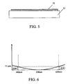
- FIG. 5 illustrates a structure of a phase plate used for a first embodiment.
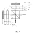
- FIG. 6 illustrates a characteristic of a longitudinal chromatic aberration of a projection lens used for the first embodiment.
- FIG. 7 illustrates an arrangement among a polarization beam splitter, phase plates, and image display elements according to the first embodiment.
- FIG. 8 illustrates a characteristic of the polarization beam splitter of this embodiment.
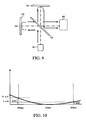
- FIG. 9 is a view illustrating an optical element using a principle of a Michelson interferometer.
- FIG. 10 illustrates a characteristic of a longitudinal chromatic aberration of a projection used for second and third embodiments.
- This embodiment addresses lengths of two optical paths which cause interference, provides an optical synthesis system with a proper optical length that can reduce an aberration, and maintains a leak-light generating optical system in a non-interference state.
- FIG. 1 illustrates a structure of an image projection apparatus of this embodiment.
- a polarization beam splitter (also referred to as a "PBS” hereinafter) has a characteristic in that it allows p-polarized light to transmit through it and reflects s-polarized light.
- a wavelength selective phase plate has a characteristic of rotating a phase of a predetermined wavelength band.
- blue color light is referred to as B light (first color light or blue band)
- green color light is referred to as G light (third color light or green band)
- red color light is referred to as R light (second color light or red band).
- the B light has a gravity center wavelength ⁇ 1 of 440 nm
- the G light has a gravity center wavelength ⁇ 3 of 550 nm
- the R light has a gravity center wavelength ⁇ 2 of 620 nm.
- the gravity center wavelength means a wavelength corresponding to a center of gravity calculated from a product between a screen spectrum that is a spectrum of the light flux emitted from the projector illustrated in FIG. 2 and a corresponding color matching function illustrated in FIG. 3 .
- the screen spectrum illustrated in FIG. 2 is obtained by measuring light emitted from the projector using a spectroradiometer and a scattering plate.
- FIG. 4 is a product between each color light (B light, G light, and R light) illustrated in FIG.
- Wavelengths corresponding to lines crossing the abscissa axis of FIG. 4 indicate gravity center wavelengths of the respective wavelength bands. The gravity center is calculated from the weighted average of each wavelength band illustrated in FIG. 4 .
- reference numeral 1 denotes a light source, which uses a high pressure mercury lamp in this embodiment.
- Reference numeral 2 denotes a parabolic reflector
- reference numeral 3 denotes a first lens array
- reference numeral 4 denotes a second lens array.
- Reference numeral 5 denotes a polarization converter
- reference numeral 6 denotes a condenser lens.
- the "lens array,” as used herein, means an optical element in which a plurality of micro lenses are arranged.
- Reference numeral 7 denotes a dichroic mirror that serves as a color splitter
- reference numeral 8 denotes a polarizing plate
- reference numeral 9 denotes a polarization beam splitter configured to allow the p-polarized light to transmit through its polarization splitting plane, and to reflect the s-polarized light on the polarization splitting plane.
- Polarization splitting films are laminated on the polarization splitting plane.
- Reference numeral 10 denotes a phase plate
- reference numeral 11 denotes a G-use image display element configured to optically modulate the G light.
- a more specific element of the image display element in this embodiment is a reflective liquid crystal display element LCOS, a DMD element (DLP), etc.
- Reference numeral 13 denotes a polarizing plate.
- Reference numeral 14 denotes a wavelength selective phase plate configured to rotate the polarization direction of only the B light by 90°.
- Reference numeral 15 denotes a polarization beam splitter configured to allow the p-polarized light to transmit through its polarization splitting plane, and to reflect the s-polarized light on the polarization splitting plane.
- Reference numeral 16 denotes a phase plate.
- Reference numeral 17 denotes a B-use image display element (first reflective image display element) configured to rotate the polarization direction of only the B light by 90°.
- Reference numeral 18 denotes a phase plate.
- Reference numeral 19 denotes an R-use image display element (second reflective image display element) configured to optically modulate the R light.
- Reference numeral 20 denotes a wavelength selective phase plate configured to rotate only the R light by 90°.
- Reference numeral 12 denotes a polarization beam splitter configured to allow the p-polarized light to transmit through its polarization splitting plane, and to reflect the s-polarized light on the polarization splitting plane.
- Reference numeral 21 denotes a projection lens (projection optical system) configured to project an image onto a projection surface.
- each of the parallel plate 31 (first parallel plate) used for phase plate 16 and the parallel plate 31 (second parallel plate) used for phase plate 18 has the same thickness D of 1.5 mm, and is made of the same glass material S-TIH53.
- the parallel plate 31 for each of the phase plates 16, 18 is conventionally made of an inexpensive white plate glass, but this embodiment utilizes a high-dispersion glass material S-TIH53.
- This embodiment characteristically arranges a glass material having a refractive index wavelength dispersion in a single optical path between the polarization beam splitter 15 and each image display element, and utilizes a high dispersion glass material for the parallel plate 31, avoiding an interference pattern as described later. While this embodiment utilizes the same material for the parallel plate 31 between the phase plates 16, 18, the glass material of the parallel plate 31 for the phase plate 16 may be different from that for the phase plate 18 as in a third embodiment, which will be described later. In other words, a proper glass material may be used for each of the phase plates 16 and 18 for the transmittance to the R or B light, costs, etc. of the glass material of the parallel plate 31.
- the high dispersion glass material used for the parallel plate 31 for the phase plate 16 may be S-TIH53, and the high dispersion glass material used for the parallel plate 31 for the phase plate 18 (R optical path) may be such a different material as S-LAH79.
- the glass material S-LAH79 has a large refractive index wavelength dispersion but its transmittance to the B band is too low for the phase plate 16 (B optical path).
- the parallel plate for phase plate 16 may have a thickness different from that of the parallel plate for phase plate 18.
- the refractive index of each wavelength of the glass material S-TIH53 used for this embodiment is 1.894 for 440 nm and 1.841 for 620 nm.
- FIG. 6 illustrates a characteristic of the longitudinal chromatic aberration of the projection lens 21 used for this embodiment. In the graph, this characteristic is expressed as an imaging position of each wavelength on the basis of the imaging position of the gravity center wavelength 550 nm of the G light.
- a longitudinal chromatic aberration amount ⁇ B1 for the gravity center wavelength ⁇ 1 (440 nm) of the B light and a longitudinal chromatic aberration amount ⁇ R1 for the gravity center wavelength ⁇ 2 (620 nm) of the R light have the same value of 15 ⁇ m.
- the fixing position of the image display element corresponding to each color light is determined based on the gravity center wavelength of each color light.
- each corresponding optical path has the same optical path length. In other words, the image display element of each color light is fixed onto that position.
- FIG. 7 illustrates an arrangement among the polarization beam splitter 15, the phase plates 16, 18, and the image display elements 17, 19 of this embodiment.
- Distances from the polarization beam splitter 15 to the phase plates 16, 18 are 2.0 mm.
- the image display element 17 is fixed at a position in which a distance between the phase plate 16 and the B-use image display element 17 is 3.208 mm.
- the image display element 19 is fixed at a position in which a distance between the phase plate 18 and the R-use image display element 19 is 3.1853 mm.
- Table 1 summarizes numerical values.
- This embodiment uses the same glass material, and the same thickness d of 1.5 mm for the phase plates 16 and 18. While the phase plate includes the parallel plate 31 and the film 32, as described above, the film 32 is very thin and thus the thickness d of the phase plate means a thickness of the parallel plate 31 in this embodiment.
- "n" is a refractive index. Even when the phase plates 16 and 18 are made of the same glass material, the refractive index (1.894) to the gravity center wavelength of the B light is different from the refractive index (1.841) to the gravity center wavelength of the R light. Thus, the refractive index n of the phase plate (parallel plate 31) is differently illustrated in Table 1.
- FIG. 8 illustrates one example of the optical characteristic of the polarization beam splitter. It is understood that the p-polarized light is deteriorated in the transmission and the s-polarized light is deteriorated in the reflection over all incident angles including the ideal incident angle of 45°.
- the interference pattern occurs with the same wavelength.
- the interference pattern occurs when a light flux of color light is split into a normal optical path and a non-normal optical path due to the leak light of the optical component, the split light fluxes again immerge, and the distance between the normal optical path and non-normal optical path falls within a predetermined distance (coherent distance L).
- a description will be given of the B light with reference to FIG. 7 .
- the B light incident as p-polarized light upon the PBS 15 transmits the PBS 15, and passes the B-use optical path as the normal optical path. However, a small amount of B light is reflected on the PBS 15, and passes the R-use optical path as the non-normal optical path.
- the optical path length of the normal optical path for the B light is 6.0 mm.
- the non-normal optical path has the same length of 2.0 mm as the normal optical path from the polarization beam splitter 15 to the phase plate 18.
- a length difference between the normal optical path and the non-normal optical path is 22.7 ⁇ m for the B light.
- the coherent distance of the light source 1 used for this optical system is about 30 ⁇ m, and no interference pattern occurs when there is an optical path length difference of about 15 ⁇ m or larger on one side between the polarization beam splitter 15 and the image display element.
- another light source different from the light source 1 if it has a coherent distance of about 30 ⁇ m or smaller, no interference pattern occurs when there is an optical path length difference of about 15 ⁇ m or larger on one side between the polarization beam splitter 15 and the image display element.
- this embodiment can avoid an interference pattern even with an achromatic projection lens.
- FIG. 9 illustrates an optical system utilizing a principle of a Michelson interferometer.
- Reference numeral 41 denotes a light source
- reference numeral 42 denotes a half-mirror
- reference numeral 43 denotes a first mirror
- reference numeral 44 denotes a second mirror
- reference numeral 45 denotes a light receiving unit.
- light from the light source 41 is split by the half-mirror 42, and the light reflected on the half-mirror 42 is reflected on the first mirror 43, then transmits the half-mirror 42, and reaches the light receiving unit 45.
- the light that has transmitted the half-mirror 42 is reflected on the second mirror 44, is reflected on the half-mirror 42, and reaches the light receiving unit 45.
- the light that has been reflected on the half-mirror 42 and the light that has transmitted the half-mirror 42 are synthesized by the half-mirror and interfere with each other when an optical path length between both optical paths is equal to or smaller than the predetermined distance.
- This predetermined distance will be referred to as a coherent distance.
- One calculating method of the coherent distance is to fix one of the first mirror 43 and the second mirror 44, and to shift the other mirror in the optical axis direction.
- the coherent distance corresponds to a shift amount range in which the interference pattern occurs and disappears.
- the length distance between the normal optical path and the non-normal optical path is 22.7 ⁇ m for the B light, and the length distance between the normal optical path and the non-normal optical path is 22.8 ⁇ m for the R light.
- Each length difference between the normal optical path and the non-normal optical path may be set larger, but there is no specific influence upon the interference pattern. Conversely, such a configuration would increase a size of the optical system and the cost.
- the length difference between the normal optical path and the non-normal optical path may be ten times as large as the coherent distance (or 5L) or smaller. (Expression 1) 5 ⁇ L ⁇ ABS D ⁇ 1 n ⁇ 22 - 1 n ⁇ 21 ⁇ L 2 5 ⁇ L ⁇ ABS D ⁇ 1 n ⁇ 11 - 1 n ⁇ 12 ⁇ L 2
- This embodiment can remarkably improve a degree of freedom of glass by slightly sacrificing color-erasing conditions without sacrificing the resolving power of the projection lens.
- the present invention is applied in accordance with the color erasing condition.
- This embodiment also uses the image projection apparatus illustrated in FIG. 1 .
- the differences from the first embodiment are a characteristic of the projection lens and a fixing position of each image display element.
- FIG. 10 illustrates a characteristic of the longitudinal chromatic aberration of the projection lens used for this embodiment.
- the B light has a gravity center wavelength of 440 nm
- the G light has a gravity center wavelength of 550 nm
- the R light has a gravity center wavelength of 620 nm.
- a longitudinal chromatic aberration amount ⁇ B1 (T1) for the gravity center wavelength of the B light of the projection lens used for this embodiment is 15 ⁇ m.
- a longitudinal chromatic aberration amount ⁇ R1 (T2) for the gravity center wavelength of the R light have the same value of 5 ⁇ m.
- a longitudinal chromatic aberration of 10 ⁇ m is generated between the gravity center wavelength of the B light and the gravity center wavelength of the R light.
- a thickness d of each phase plate is 1.5 mm, and a glass material used for the parallel plate 31 is S-TIM22.
- the refractive index of the glass material is 1.673 for 440 nm, and 1.645 for 620 nm.
- an interval between the polarization beam splitter and each phase plate is set to 2.0 mm.
- a distance (in air) from the polarization beam splitter 15 to each image display element is 6.0 mm for the R optical path, and 6.01 mm for the B optical path. This difference is caused by the color erasing condition of the projection lens.
- 1.673 is the refractive index n11 of the phase plate 16 for the gravity center wavelength of the B light.
- 1.645 is the refractive index n22 of the phase plate 18 for the gravity center wavelength of the R light.
- the normal optical path is as long as 6.01 mm.
- 1.673 is the refractive index n21 of the phase plate 18 for the gravity center wavelength of the B light.
- the normal optical path is as long as 6.0 mm.
- 1.645 is the refractive index n12 of the phase plate 16 for the gravity center wavelength of the R light.
- this embodiment can avoid the interference pattern and thereby remarkably improve a degree of freedom of glass by slightly sacrificing color-erasing conditions without sacrificing the resolving power of the projection lens.
- Table 4 Fixing positions of the B and R panels B panel fixing position R panel fixing position d n In air d n In air PBS-phase plate 2 1 2 2 1 2 Phase plate 1.5 1.673 0.897 1.5 1.645 0.912 Phase plate to panel 3.113 1 3.113 3.0881 1 3.088 Total 6.01 6.00 *Unit of d in Table 4 is millimeter (Table 5) Optical path length of each of normal optical path and non-abnormal optical path for B Normal optical path for B light Non-normal optical path for B light d n In air d n In air PBS-phase plate 2 1 2 2 1 2 Phase plate 1.5 1.673 0.8966 1.5 1.673 0.8966 Phase plate to panel 3.113 1 3.113 3.0881 1 3.088 Total 6.01 5.985 *Unit of d in Table 5 is millimeter (
- this embodiment uses the image projection apparatus illustrated in FIG. 1 , and the projection lens having a longitudinal chromatic aberration illustrated in FIG. 10 .
- the difference from the second embodiment is that the glass material of the parallel plate 31 is different between the phase plate 16 and the phase plate 18.
- the thickness of the phase plate 16 is also different from that of the phase plate 18.
- the B light has a gravity center wavelength of 440 nm
- the G light has a gravity center wavelength of 550 nm
- the R light has a gravity center wavelength of 620 nm.
- a longitudinal chromatic aberration amount ⁇ B1 (T1) of the projection lens used for this embodiment for the gravity center wavelength of the B light is 15 ⁇ m.
- a longitudinal chromatic aberration amount ⁇ R1 (T2) for the gravity center wavelength of the R light have the same value of 5 ⁇ m.
- a longitudinal chromatic aberration of 10 ⁇ m is generated between the gravity center wavelength of the B light and the gravity center wavelength of the R light.
- the thickness D1 of the B-use phase plate 16 is 2.0 mm, and the thickness D2 of the R-use phase plate 18 is 1.5 mm.
- the glass material used for the B-use phase plate 16 is S-TIM22, and the glass material used for the R-use phase plate 18 is S-LAH79.
- the refractive index of S-TIM22 is 1.673 for 440 nm, and 1.645 for 620 nm.
- the refractive index of S-LAH79 is 2.05 for 440 nm, and 1.998 for 620 nm.
- an interval between the polarization beam splitter and each phase plate is set to 2.0 mm.
- a distance (in air) from the polarization beam splitter 15 to each image display element is 6.0 mm for the R optical path, and 6.01 mm for the B optical path. This difference is caused by the color erasing condition of the projection lens.
- 1.673 is the refractive index n11 of the phase plate 16 for the gravity center wavelength of the B light.
- 1.998 is the refractive index n22 of the phase plate 18 for the gravity center wavelength of the R light.
- the normal optical path is as long as 6.01 mm.
- 2.05 is the refractive index n21 of the phase plate 18 for the gravity center wavelength of the B light.
- the normal optical path is as long as 6.0 mm.
- 1.645 is the refractive index n12 of the phase plate 16 of the gravity center wavelength of the R light.
- this embodiment can also avoid the interference pattern.
- this embodiment can avoid the interference pattern without causing a large longitudinal chromatic aberration in the projection lens, and provide an image projection apparatus that can reduce the chromatic blur.
- this embodiment is free of a restraint of the predetermined chromatic aberration to be generated in the conventional projection lens design, and can improve the imaging performance without considering the interference pattern.
- the conditions that provide the effects of the present invention will be formulated as follows: 5 ⁇ L ⁇ ABS T ⁇ 1 - T ⁇ 2 + D ⁇ 2 ⁇ 1 n ⁇ 22 - 1 n ⁇ 21 ⁇ L 2 5 ⁇ L ⁇ ABS T ⁇ 2 - T ⁇ 1 + D ⁇ 1 ⁇ 1 n ⁇ 11 - 1 n ⁇ 12 ⁇ L 2 T ⁇ 2 , T ⁇ 1 ⁇ 20 ⁇ m
- the longitudinal chromatic aberrations T1 and T2 and the refractive indexes n11, n12, n21, and n22 may satisfy one of T1>T2 and n21>n22 and n11>n12, and T2>T1 and n22>n21 and n12>n11 so as to easily avoid the interference pattern.
- the color splitting optical system is applicable to the image projection apparatus, and the image projection apparatus is applicable to an application of projecting an image.
Description
- The present invention relates to an image projection apparatus that utilizes a reflective image display element.
- An image projection apparatus utilizing a reflective image display element has a known problem in that light that is to totally transmit through a polarization splitting film of a polarization beam splitter is partially reflected on the polarization splitting film, and a small amount of reflected light and the transmitting light generate an interference pattern.
- Accordingly, each of Japanese Patent Laid-Open Nos.
2006-047967 2006-343692 - Japanese Patent Laid-Open Nos.
2006-047967 2006-343692 - The present invention provides an image projection apparatus which can restrain a generation of an interference pattern, and reduce color blurs.
- The present invention in its first aspect provides an image projection apparatus as specified in claims 1 to 6.
- Further features of the present invention will become apparent from the following description of exemplary embodiments with reference to the attached drawings.
-
FIG. 1 illustrates a structure of an image projection apparatus of this embodiment. -
FIG. 2 is a graph illustrating a (screen) spectrum of a light flux emitted from the image projection apparatus of this embodiment. -
FIG. 3 is a graph illustrating RGB color matching functions. -
FIG. 4 is a graph illustrating a product between the screen spectrum illustrated inFIG. 2 and the color matching function illustrated inFIG. 3 , and gravity center wavelengths. -
FIG. 5 illustrates a structure of a phase plate used for a first embodiment. -
FIG. 6 illustrates a characteristic of a longitudinal chromatic aberration of a projection lens used for the first embodiment. -
FIG. 7 illustrates an arrangement among a polarization beam splitter, phase plates, and image display elements according to the first embodiment. -
FIG. 8 illustrates a characteristic of the polarization beam splitter of this embodiment. -
FIG. 9 is a view illustrating an optical element using a principle of a Michelson interferometer. -
FIG. 10 illustrates a characteristic of a longitudinal chromatic aberration of a projection used for second and third embodiments. - A detailed description will now be given of embodiments of this invention with reference to the accompanying drawings. Those elements in each figure, which are the same as corresponding elements, will be labeled by the same reference numeral, and a duplicate description thereof will be omitted.
- This embodiment addresses lengths of two optical paths which cause interference, provides an optical synthesis system with a proper optical length that can reduce an aberration, and maintains a leak-light generating optical system in a non-interference state.
-
FIG. 1 illustrates a structure of an image projection apparatus of this embodiment. - A description will now be given of a function of each component and a variety of definitions used for this embodiment. A polarization beam splitter (also referred to as a "PBS" hereinafter) has a characteristic in that it allows p-polarized light to transmit through it and reflects s-polarized light. A wavelength selective phase plate has a characteristic of rotating a phase of a predetermined wavelength band. In addition, blue color light is referred to as B light (first color light or blue band), green color light is referred to as G light (third color light or green band), and red color light is referred to as R light (second color light or red band). The B light has a gravity center wavelength λ1 of 440 nm, the G light has a gravity center wavelength λ3 of 550 nm, and the R light has a gravity center wavelength λ2 of 620 nm. The gravity center wavelength, as used herein, means a wavelength corresponding to a center of gravity calculated from a product between a screen spectrum that is a spectrum of the light flux emitted from the projector illustrated in
FIG. 2 and a corresponding color matching function illustrated inFIG. 3 . The screen spectrum illustrated inFIG. 2 is obtained by measuring light emitted from the projector using a spectroradiometer and a scattering plate.FIG. 4 is a product between each color light (B light, G light, and R light) illustrated inFIG. 2 , and each color light of the color matching function illustrated inFIG. 3 . Wavelengths corresponding to lines crossing the abscissa axis ofFIG. 4 indicate gravity center wavelengths of the respective wavelength bands. The gravity center is calculated from the weighted average of each wavelength band illustrated inFIG. 4 . - In
FIG. 1 , reference numeral 1 denotes a light source, which uses a high pressure mercury lamp in this embodiment.Reference numeral 2 denotes a parabolic reflector, reference numeral 3 denotes a first lens array, andreference numeral 4 denotes a second lens array.Reference numeral 5 denotes a polarization converter, andreference numeral 6 denotes a condenser lens. The "lens array," as used herein, means an optical element in which a plurality of micro lenses are arranged. Reference numeral 7 denotes a dichroic mirror that serves as a color splitter,reference numeral 8 denotes a polarizing plate, and reference numeral 9 denotes a polarization beam splitter configured to allow the p-polarized light to transmit through its polarization splitting plane, and to reflect the s-polarized light on the polarization splitting plane. - Polarization splitting films are laminated on the polarization splitting plane.
Reference numeral 10 denotes a phase plate, andreference numeral 11 denotes a G-use image display element configured to optically modulate the G light. A more specific element of the image display element in this embodiment is a reflective liquid crystal display element LCOS, a DMD element (DLP), etc.Reference numeral 13 denotes a polarizing plate.Reference numeral 14 denotes a wavelength selective phase plate configured to rotate the polarization direction of only the B light by 90°.Reference numeral 15 denotes a polarization beam splitter configured to allow the p-polarized light to transmit through its polarization splitting plane, and to reflect the s-polarized light on the polarization splitting plane.Reference numeral 16 denotes a phase plate.Reference numeral 17 denotes a B-use image display element (first reflective image display element) configured to rotate the polarization direction of only the B light by 90°.Reference numeral 18 denotes a phase plate.Reference numeral 19 denotes an R-use image display element (second reflective image display element) configured to optically modulate the R light.Reference numeral 20 denotes a wavelength selective phase plate configured to rotate only the R light by 90°.Reference numeral 12 denotes a polarization beam splitter configured to allow the p-polarized light to transmit through its polarization splitting plane, and to reflect the s-polarized light on the polarization splitting plane.Reference numeral 21 denotes a projection lens (projection optical system) configured to project an image onto a projection surface. - The
phase plates FIG. 5 in which afilm 32 is adhered onto one surface of aparallel plate 31. In this embodiment, each of the parallel plate 31 (first parallel plate) used forphase plate 16 and the parallel plate 31 (second parallel plate) used forphase plate 18 has the same thickness D of 1.5 mm, and is made of the same glass material S-TIH53. Theparallel plate 31 for each of thephase plates polarization beam splitter 15 and each image display element, and utilizes a high dispersion glass material for theparallel plate 31, avoiding an interference pattern as described later. While this embodiment utilizes the same material for theparallel plate 31 between thephase plates parallel plate 31 for thephase plate 16 may be different from that for thephase plate 18 as in a third embodiment, which will be described later. In other words, a proper glass material may be used for each of thephase plates parallel plate 31. More specifically, the high dispersion glass material used for theparallel plate 31 for the phase plate 16 (B optical path) may be S-TIH53, and the high dispersion glass material used for theparallel plate 31 for the phase plate 18 (R optical path) may be such a different material as S-LAH79. The glass material S-LAH79 has a large refractive index wavelength dispersion but its transmittance to the B band is too low for the phase plate 16 (B optical path). In addition, the parallel plate forphase plate 16 may have a thickness different from that of the parallel plate forphase plate 18. - The refractive index of each wavelength of the glass material S-TIH53 used for this embodiment is 1.894 for 440 nm and 1.841 for 620 nm.
FIG. 6 illustrates a characteristic of the longitudinal chromatic aberration of theprojection lens 21 used for this embodiment. In the graph, this characteristic is expressed as an imaging position of each wavelength on the basis of the imaging position of thegravity center wavelength 550 nm of the G light. In this illustration, a longitudinal chromatic aberration amount ΔB1 for the gravity center wavelength λ1 (440 nm) of the B light and a longitudinal chromatic aberration amount ΔR1 for the gravity center wavelength λ2 (620 nm) of the R light have the same value of 15 µm. - A description will be given of a determination of a fixing position of the image display element which is important in implementing this embodiment.
- The fixing position of the image display element corresponding to each color light is determined based on the gravity center wavelength of each color light.
- Since the longitudinal chromatic aberration based on the
gravity center wavelength 550 nm of the G light of the projection lens used for this embodiment is the same between the gravity center wavelength 440 nm of the B light the gravity center wavelength 620 nm of the R light as illustrated inFIG. 6 , each corresponding optical path has the same optical path length. In other words, the image display element of each color light is fixed onto that position. - This method will be discussed in more detail with reference to
FIG. 7. FIG. 7 illustrates an arrangement among thepolarization beam splitter 15, thephase plates image display elements polarization beam splitter 15 to thephase plates polarization beam splitter 15 to each of theimage display elements image display element 17 is fixed at a position in which a distance between thephase plate 16 and the B-useimage display element 17 is 3.208 mm. Theimage display element 19 is fixed at a position in which a distance between thephase plate 18 and the R-useimage display element 19 is 3.1853 mm. Table 1 summarizes numerical values.(Table 1) Fixing positions of the B and R panels B panel fixing position R panel fixing position d n In air d n In air PBS- phase plate 2 1 2 2 1 2 Phase plate 1.5 1.894 0.792 1.5 1.841 0.8147 Phase plate to panel 3.208 1 3.208 3.1853 1 3.1853 Total 6.00 6.00 *Unit of d in Table 1 is millimeter - This embodiment uses the same glass material, and the same thickness d of 1.5 mm for the
phase plates parallel plate 31 and thefilm 32, as described above, thefilm 32 is very thin and thus the thickness d of the phase plate means a thickness of theparallel plate 31 in this embodiment. Here, "n" is a refractive index. Even when thephase plates - A description will now be give of a generation of an interference pattern.
- None of currently available optical components, such as a wavelength selective phase plate, a polarization beam splitter, and an image display element, have ideal optical characteristics, and cause leak light which is different according to incident polarized light and the incident angle.
FIG. 8 illustrates one example of the optical characteristic of the polarization beam splitter. It is understood that the p-polarized light is deteriorated in the transmission and the s-polarized light is deteriorated in the reflection over all incident angles including the ideal incident angle of 45°. - The interference pattern occurs with the same wavelength. The interference pattern occurs when a light flux of color light is split into a normal optical path and a non-normal optical path due to the leak light of the optical component, the split light fluxes again immerge, and the distance between the normal optical path and non-normal optical path falls within a predetermined distance (coherent distance L). For example, a description will be given of the B light with reference to
FIG. 7 . The B light incident as p-polarized light upon thePBS 15 transmits thePBS 15, and passes the B-use optical path as the normal optical path. However, a small amount of B light is reflected on thePBS 15, and passes the R-use optical path as the non-normal optical path. When these light fluxes are reflected on corresponding image display elements and again synthesized at thePBS 15, and when an optical path length difference between the normal optical path and the non-normal optical path falls within the predetermined distance, the interference pattern occurs. An optical path length from thepolarization beam splitter 15 to each image display element for the B light will be calculated for each of the normal optical path and the non-normal optical path. Table 2 summarizes numerical values. - The optical path length of the normal optical path for the B light is 6.0 mm. The non-normal optical path has the same length of 2.0 mm as the normal optical path from the
polarization beam splitter 15 to thephase plate 18. However, a distance from thephase plate 18 to the R-useimage display element 19 is as long as 3.1853 mm as described above, and thephase plate 18 is as long as 1.5/1.894=0.792 mm. Therefore, the total is 5.9773 mm. - Therefore, a length difference between the normal optical path and the non-normal optical path is 22.7 µm for the B light.
- Similarly, a length difference between the normal optical path and the non-normal optical path is -22.8 µm for the R light. Table 3 summarizes numerical values.
- The coherent distance of the light source 1 used for this optical system is about 30 µm, and no interference pattern occurs when there is an optical path length difference of about 15 µm or larger on one side between the
polarization beam splitter 15 and the image display element. When another light source different from the light source 1 is used, if it has a coherent distance of about 30 µm or smaller, no interference pattern occurs when there is an optical path length difference of about 15 µm or larger on one side between thepolarization beam splitter 15 and the image display element. - Hence, this embodiment can avoid an interference pattern even with an achromatic projection lens.
- Referring now to
FIG. 9 , a description will be given of a calculation of a coherent distance.FIG. 9 illustrates an optical system utilizing a principle of a Michelson interferometer.Reference numeral 41 denotes a light source,reference numeral 42 denotes a half-mirror,reference numeral 43 denotes a first mirror,reference numeral 44 denotes a second mirror, andreference numeral 45 denotes a light receiving unit. In the optical operation, light from thelight source 41 is split by the half-mirror 42, and the light reflected on the half-mirror 42 is reflected on thefirst mirror 43, then transmits the half-mirror 42, and reaches thelight receiving unit 45. On the other hand, the light that has transmitted the half-mirror 42 is reflected on thesecond mirror 44, is reflected on the half-mirror 42, and reaches thelight receiving unit 45. The light that has been reflected on the half-mirror 42 and the light that has transmitted the half-mirror 42 are synthesized by the half-mirror and interfere with each other when an optical path length between both optical paths is equal to or smaller than the predetermined distance. This predetermined distance will be referred to as a coherent distance. One calculating method of the coherent distance is to fix one of thefirst mirror 43 and thesecond mirror 44, and to shift the other mirror in the optical axis direction. The coherent distance corresponds to a shift amount range in which the interference pattern occurs and disappears. - In the first embodiment, conditions that satisfy the effect of this embodiment are formulated as follows:
- In this embodiment, the length distance between the normal optical path and the non-normal optical path is 22.7 µm for the B light, and the length distance between the normal optical path and the non-normal optical path is 22.8 µm for the R light. Each length difference between the normal optical path and the non-normal optical path may be set larger, but there is no specific influence upon the interference pattern. Conversely, such a configuration would increase a size of the optical system and the cost. Hence, the length difference between the normal optical path and the non-normal optical path may be ten times as large as the coherent distance (or 5L) or smaller. (Expression 1)


- n11 is a refractive index of the first parallel plate for a gravity center wavelength λ1 of the first color light;
- n12 is a refractive index of the first parallel plate for a gravity center wavelength λ2 of the second color light;
- n21 is a refractive index of the second parallel plate for a gravity center wavelength λ1 of the first color light;
- n22 is a refractive index of the second parallel plate for a gravity center wavelength λ2 of the second color light;
- D (µm) is a thickness of the parallel plate;
- L (µm) is a coherent distance of the light source:
- This embodiment can remarkably improve a degree of freedom of glass by slightly sacrificing color-erasing conditions without sacrificing the resolving power of the projection lens. In the following embodiment, the present invention is applied in accordance with the color erasing condition.
- This embodiment also uses the image projection apparatus illustrated in
FIG. 1 . The differences from the first embodiment are a characteristic of the projection lens and a fixing position of each image display element. -
FIG. 10 illustrates a characteristic of the longitudinal chromatic aberration of the projection lens used for this embodiment. - Even in this embodiment, the B light has a gravity center wavelength of 440 nm, the G light has a gravity center wavelength of 550 nm, and the R light has a gravity center wavelength of 620 nm. As illustrated in
FIG. 10 , a longitudinal chromatic aberration amount ΔB1 (T1) for the gravity center wavelength of the B light of the projection lens used for this embodiment is 15 µm. A longitudinal chromatic aberration amount ΔR1 (T2) for the gravity center wavelength of the R light have the same value of 5 µm. A longitudinal chromatic aberration of 10 µm is generated between the gravity center wavelength of the B light and the gravity center wavelength of the R light. - A thickness d of each phase plate is 1.5 mm, and a glass material used for the
parallel plate 31 is S-TIM22. The refractive index of the glass material is 1.673 for 440 nm, and 1.645 for 620 nm. - Similar to the first embodiment, a fixing position of each image display element will be calculated.
- Similar to the first embodiment, an interval between the polarization beam splitter and each phase plate is set to 2.0 mm.
- A distance (in air) from the
polarization beam splitter 15 to each image display element is 6.0 mm for the R optical path, and 6.01 mm for the B optical path. This difference is caused by the color erasing condition of the projection lens. - A fixing position will be calculated. Table 4 summarizes numerical values.
- Initially, in the calculation of the
image display element 17 for the B light, a distance from thephase plate 16 to the B-useimage display element 17 is 6.01 mm-2.0mm-1.5/1.673=3.113 mm. 1.673 is the refractive index n11 of thephase plate 16 for the gravity center wavelength of the B light. - in the calculation of the
image display element 19 for the R light, a distance from thephase plate 18 to the R-useimage display element 19 is 6.0 mm-2.0mm-1.5/1.645=3.088 mm. 1.645 is the refractive index n22 of thephase plate 18 for the gravity center wavelength of the R light. - Next, a length difference between the normal optical path and the non-normal optical path for the B light will be calculated. Table 5 summarizes numerical values.
- The normal optical path is as long as 6.01 mm. The non-normal optical path is as long as 2.0+1.5/1.673+3.088=5.985 mm. Thus, a length difference between the normal optical path and the non-normal optical path is 0.025 mm=25µm. 1.673 is the refractive index n21 of the
phase plate 18 for the gravity center wavelength of the B light. - Similarly, a length difference between the normal optical path and the non-normal optical path for the R light will be calculated. Table 6 summarizes numerical values.
- The normal optical path is as long as 6.0 mm. The non-normal optical path is as long as 2.0+1.5/1.645+3.113=6.025 mm. Thus, a length difference between the normal optical path and the non-normal optical path is 0.025 mm=25µm. 1.645 is the refractive index n12 of the
phase plate 16 for the gravity center wavelength of the R light. - Hence, this embodiment can avoid the interference pattern and thereby remarkably improve a degree of freedom of glass by slightly sacrificing color-erasing conditions without sacrificing the resolving power of the projection lens.
(Table 4) Fixing positions of the B and R panels B panel fixing position R panel fixing position d n In air d n In air PBS- phase plate 2 1 2 2 1 2 Phase plate 1.5 1.673 0.897 1.5 1.645 0.912 Phase plate to panel 3.113 1 3.113 3.0881 1 3.088 Total 6.01 6.00 *Unit of d in Table 4 is millimeter (Table 5) Optical path length of each of normal optical path and non-abnormal optical path for B Normal optical path for B light Non-normal optical path for B light d n In air d n In air PBS- phase plate 2 1 2 2 1 2 Phase plate 1.5 1.673 0.8966 1.5 1.673 0.8966 Phase plate to panel 3.113 1 3.113 3.0881 1 3.088 Total 6.01 5.985 *Unit of d in Table 5 is millimeter (Table 6) Optical path length of each of normal optical path and non-abnormal optical path for R Normal optical path for R light Non-normal optical path for R light d n In air d n In air PBS- phase plate 2 1 2 2 1 2 Phase plates 1.5 1.645 0.912 1.5 1.645 0.912 Phase plate to panel 3.0881 1 3.088 3.113 1 3.113 Total 6.00 6.025 *Unit of d in Table 6 is millimeter - Similar to the second embodiment, this embodiment uses the image projection apparatus illustrated in
FIG. 1 , and the projection lens having a longitudinal chromatic aberration illustrated inFIG. 10 . The difference from the second embodiment is that the glass material of theparallel plate 31 is different between thephase plate 16 and thephase plate 18. The thickness of thephase plate 16 is also different from that of thephase plate 18. - Even in this embodiment, the B light has a gravity center wavelength of 440 nm, the G light has a gravity center wavelength of 550 nm, and the R light has a gravity center wavelength of 620 nm. As illustrated in
FIG. 10 , a longitudinal chromatic aberration amount ΔB1 (T1) of the projection lens used for this embodiment for the gravity center wavelength of the B light is 15 µm. A longitudinal chromatic aberration amount ΔR1 (T2) for the gravity center wavelength of the R light have the same value of 5 µm. A longitudinal chromatic aberration of 10 µm is generated between the gravity center wavelength of the B light and the gravity center wavelength of the R light. - The thickness D1 of the B-
use phase plate 16 is 2.0 mm, and the thickness D2 of the R-use phase plate 18 is 1.5 mm. The glass material used for the B-use phase plate 16 is S-TIM22, and the glass material used for the R-use phase plate 18 is S-LAH79. The refractive index of S-TIM22 is 1.673 for 440 nm, and 1.645 for 620 nm. The refractive index of S-LAH79 is 2.05 for 440 nm, and 1.998 for 620 nm. - Similar to the first and second embodiments, a fixing position of each image display element will be calculated.
- Similar to the first and second embodiments, an interval between the polarization beam splitter and each phase plate is set to 2.0 mm.
- A distance (in air) from the
polarization beam splitter 15 to each image display element is 6.0 mm for the R optical path, and 6.01 mm for the B optical path. This difference is caused by the color erasing condition of the projection lens. - A fixing position will be calculated. Table 7 summarizes numerical values.
- Initially, in the calculation of the
image display element 17 for the B light, a distance from thephase plate 16 to the B-useimage display element 17 is 6.01 mm-2.0mm-2.0/1.673=2.815 mm. 1.673 is the refractive index n11 of thephase plate 16 for the gravity center wavelength of the B light. - In the calculation of the
image display element 19 for the R light, a distance from thephase plate 18 to the R-useimage display element 19 is 6.0 mm-2.0mm-1.5/1.998=3.249 mm. 1.998 is the refractive index n22 of thephase plate 18 for the gravity center wavelength of the R light. - Next, a length difference between the normal optical path and the non-normal optical path for the B light will be calculated. Table 8 summarizes numerical values.
- The normal optical path is as long as 6.01 mm. The non-normal optical path is as long as 2.0+1.5/2.05+3.249=5.981 mm. Thus, a length difference between the normal optical path and the non-normal optical path is 0.029 mm=29µm. 2.05 is the refractive index n21 of the
phase plate 18 for the gravity center wavelength of the B light. - Similarly, a length difference between the normal optical path and the non-normal optical path for the R light will be calculated. Table 9 summarizes numerical values.
- The normal optical path is as long as 6.0 mm. The non-normal optical path is as long as 2.0+2.0/1.645+2.815=6.03 mm. Thus, a length difference between the normal optical path and the non-normal optical path is 0.03 mm=30µm. 1.645 is the refractive index n12 of the
phase plate 16 of the gravity center wavelength of the R light. - Hence, this embodiment can also avoid the interference pattern.
- Thus, this embodiment can avoid the interference pattern without causing a large longitudinal chromatic aberration in the projection lens, and provide an image projection apparatus that can reduce the chromatic blur. In addition, this embodiment is free of a restraint of the predetermined chromatic aberration to be generated in the conventional projection lens design, and can improve the imaging performance without considering the interference pattern.
(Table 7) Fixing positions of the B and R panels B panel fixing position R panel fixing position d n In air d n In air PBS- phase plate 2 1 2 2 1 2 Phase plate 2 1.673 1.195 1.5 1.998 0.751 Phase plate to panel 2.815 1 2.815 3.249 1 3.249 Total 6.01 6.00 *Unit of d in Table 7 is millimeter (Table 8) Optical path length of each of normal optical path and non-abnormal optical path for B Normal optical path for B light Non-normal optical path for B light d n In air d n In air PBS- phase plate 2 1 2 2 1 2 Phase plate 2 1.673 1.195 1.5 2.05 0.7317 Phase plate to panel 2.815 1 2.815 3.249 1 3.249 Total 6.01 5.981 5.981 *Unit of d in Table 8 is millimeter (Table 9) Optical path length of each of normal optical path and non-abnormal optical path for R Normal optical path for R light Non-normal optical path for R light d n In air d n In air PBS- phase plate 2 1 2 2 1 2 Phase plate 1.5 1.998 0.751 2 1.645 1.216 Phase plate to panel 3.249 1 3.249 2.815 1 2.8145 Total 6.00 6.030 *Unit of d in Table 9 is millimeter - In the second and third embodiments, the conditions that provide the effects of the present invention will be formulated as follows:


- n11 is a refractive index of the first parallel plate for a gravity center wavelength λ1 of the first color light,
- n12 is a refractive index of the first parallel plate for a gravity center wavelength λ2 of the second color light,
- n21 is a refractive index of the second parallel plate for a gravity center wavelength λ1 of the first color light,
- n22 is a refractive index of the second parallel plate for a gravity center wavelength λ2 of the second color light,
- D1 (µm) is a thickness of the first parallel plate in an optical axis direction,
- D2 (µm) is a thickness of the second parallel plate in the optical axis direction,
- T1 (µm) is a longitudinal chromatic aberration of the gravity center wavelength λ1 of the first color light based on a gravity center wavelength λ3 of third color light different from each of the first color light and the second color light,
- T2 (µm) is a longitudinal chromatic aberration of the gravity center wavelength λ2 of the second color light based on the gravity center wavelength λ3 of third color light,
- L (µm) is a coherent distance of the light source.
- In
Expression 2, the longitudinal chromatic aberrations T1 and T2, and the refractive indexes n11, n12, n21, and n22 may satisfy one of T1>T2 and n21>n22 and n11>n12, and T2>T1 and n22>n21 and n12>n11 so as to easily avoid the interference pattern. - While the present invention has been described with reference to exemplary embodiments, it is to be understood that the invention is not limited to the disclosed exemplary embodiments. The scope of the following claims is to be accorded the broadest interpretation so as to encompass all such modifications and equivalent structures and functions.
- The color splitting optical system is applicable to the image projection apparatus, and the image projection apparatus is applicable to an application of projecting an image.
| Optical path length of each of normal optical path and non-abnormal optical path for B | ||||||
| Normal optical path for B light | Non-normal optical path for B light | |||||
| d | n | In air | d | n | In air | |
| PBS- | 2 | 1 | 2 | 2 | 1 | 2 |
| Phase plate | 1.5 | 1.894 | 0.792 | 1.5 | 1.894 | 0.792 |
| Phase plate to panel | 3.208 | 1 | 3.208 | 3.1853 | 1 | 3.185 |
| Total | 6.00 | 5.9773 | ||||
| *Unit of d in Table 2 is millimeter |
| Optical path length of each of normal optical path and non-abnormal optical path for R | ||||||
| Normal optical path for R light | Non-normal optical path for R light | |||||
| d | n | In air | d | n | In air | |
| PBS- | 2 | 1 | 2 | 2 | 1 | 2 |
| Phase plate | 1.5 | 1.841 | 0.815 | 1.5 | 1.841 | 0.815 |
| Phase plate to panel | 3.1853 | 1 | 3.185 | 3.208 | 1 | 3.208 |
| Total | 6.00 | 6.0228 | ||||
| *Unit of d in Table 3 is millimeter |
Claims (6)
- An image projection apparatus comprising:a projection lens (21) configured to project an image onto a projection surface;a beam splitter (15) configured to split light from a light source into first color light and second color light;a first reflective image display element (17) configured to optically modulate the first color tight (B);a second reflective image display element (19) configured to optically modulate the second color light (R);a first parallel plate (16) arranged between the beam splitter and the first reflective image display element; anda second parallel plate (18) arranged between the beam splitter and the second reflective image display element,wherein the following expressions are satisfied where n11 is the refractive index of the first parallel plate for the gravity center wavelength λ1 of the first color light, n12 is the refractive index of the first parallel plate for the gravity center wavelength λ2 of the second color light, n21 is the refractive index of the second parallel plate for the gravity center wavelength λ1 of the first color light, n22 is the refractive index of the second parallel plate for the gravity center wavelength λ2 of the second color light, D1 (µm) is the thickness of the first parallel plate in an optical axis direction, D2 (µm) is the thickness of the second parallel plate in the optical axis direction, T1 (µm) is the longitudinal chromatic aberration of the gravity center wavelength λ1 of the first color light relative to the gravity center wavelength λ3 of a third color light different from each of the first color light and the second color light, T2 (µm) is the longitudinal chromatic aberration of the gravity center wavelength λ2 of the second color light relative to the gravity center wavelength λ3 of the third color light, and L (µm) is a coherent distance of the light source:


 wherein the gravity center wavelength is a wavelength corresponding to a center of gravity calculated from the product between the spectrum of the light flux emitted from the image projection apparatus and a color matching function.
 - The image projection apparatus according to claim 1, wherein the longitudinal chromatic aberrations T1 and T2, and the refractive indexes n11, n12, n21 , and n22 satisfy one of:


- The image projection apparatus according to claim 1 or 2, wherein the first parallel plate is made of a glass material different from that of the second parallel plate.
- The image projection apparatus according to any one of claims 1 to 3, wherein the coherent distance L is 30 µm or smaller.
- The image projection apparatus according to any one of claims 1 to 4, wherein the first color light belongs to a blue band and the second color light belongs to a red band.
- The image projection apparatus according to any one of claims 1 to 5, wherein each of the first and second reflective image display elements is one of LCOS and DLP.
Applications Claiming Priority (1)
| Application Number | Priority Date | Filing Date | Title |
|---|---|---|---|
| JP2010167195A JP5947479B2 (en) | 2010-07-26 | 2010-07-26 | Projection display |
Publications (2)
| Publication Number | Publication Date |
|---|---|
| EP2413186A1 EP2413186A1 (en) | 2012-02-01 |
| EP2413186B1 true EP2413186B1 (en) | 2013-10-02 |
Family
ID=44720474
Family Applications (1)
| Application Number | Title | Priority Date | Filing Date |
|---|---|---|---|
| EP11006023.3A Not-in-force EP2413186B1 (en) | 2010-07-26 | 2011-07-22 | Image projection apparatus |
Country Status (4)
| Country | Link |
|---|---|
| US (1) | US8704143B2 (en) |
| EP (1) | EP2413186B1 (en) |
| JP (1) | JP5947479B2 (en) |
| CN (1) | CN102346363B (en) |
Cited By (1)
| Publication number | Priority date | Publication date | Assignee | Title |
|---|---|---|---|---|
| US11846773B2 (en) | 2017-10-27 | 2023-12-19 | 3M Innovative Properties Company | Optical system |
Families Citing this family (4)
| Publication number | Priority date | Publication date | Assignee | Title |
|---|---|---|---|---|
| CN102436074B (en) * | 2010-09-29 | 2016-08-03 | 株式会社尼康 | Hot spot reduces device and projector |
| KR20140098203A (en) * | 2011-11-28 | 2014-08-07 | 쓰리엠 이노베이티브 프로퍼티즈 컴파니 | Polarizing beam splitters providing high resolution images and systems utilizing such beam splitters |
| CN108732778A (en) * | 2018-05-31 | 2018-11-02 | 东莞理工学院 | A kind of the 3D printing imaging system and imaging method of double light sources |
| CN117092662B (en) * | 2023-10-17 | 2024-02-23 | 中国科学技术大学 | Quantum interference laser radar system and method for wind field detection |
Family Cites Families (12)
| Publication number | Priority date | Publication date | Assignee | Title |
|---|---|---|---|---|
| JP3557317B2 (en) * | 1996-09-02 | 2004-08-25 | テキサス インスツルメンツ インコーポレイテツド | Projector device and color separation / synthesis device |
| JP2005283663A (en) * | 2004-03-26 | 2005-10-13 | Canon Inc | Display optical system and image projecting device |
| US7273279B2 (en) * | 2004-04-30 | 2007-09-25 | Victor Company Of Japan Limited | Projection display apparatus |
| JP4577609B2 (en) | 2004-04-30 | 2010-11-10 | 日本ビクター株式会社 | Projection display device |
| JP2006343692A (en) | 2005-06-10 | 2006-12-21 | Victor Co Of Japan Ltd | Projection display apparatus |
| US20060256289A1 (en) * | 2004-04-30 | 2006-11-16 | Yoshio Fukuzaki | Projection display apparatus |
| CN100334480C (en) * | 2004-07-16 | 2007-08-29 | 中国科学院物理研究所 | Laser color display device possessing three primary colors of red, green and blue |
| JP4510547B2 (en) * | 2004-08-09 | 2010-07-28 | キヤノン株式会社 | Polarization separating element and projection apparatus having the same |
| JP2006145943A (en) * | 2004-11-22 | 2006-06-08 | Victor Co Of Japan Ltd | Projection display apparatus |
| TWI262326B (en) * | 2005-09-30 | 2006-09-21 | Delta Electronics Inc | Method and prism for improving illumination efficiency in optical projector systems |
| JP2008122949A (en) * | 2006-10-17 | 2008-05-29 | Seiko Epson Corp | Light source device and projector |
| JP5274107B2 (en) * | 2008-05-28 | 2013-08-28 | キヤノン株式会社 | Image projection device |
-
2010
- 2010-07-26 JP JP2010167195A patent/JP5947479B2/en not_active Expired - Fee Related
-
2011
- 2011-07-21 CN CN201110212385.4A patent/CN102346363B/en not_active Expired - Fee Related
- 2011-07-22 EP EP11006023.3A patent/EP2413186B1/en not_active Not-in-force
- 2011-07-26 US US13/190,682 patent/US8704143B2/en not_active Expired - Fee Related
Cited By (1)
| Publication number | Priority date | Publication date | Assignee | Title |
|---|---|---|---|---|
| US11846773B2 (en) | 2017-10-27 | 2023-12-19 | 3M Innovative Properties Company | Optical system |
Also Published As
| Publication number | Publication date |
|---|---|
| US20120019787A1 (en) | 2012-01-26 |
| JP2012027318A (en) | 2012-02-09 |
| CN102346363A (en) | 2012-02-08 |
| EP2413186A1 (en) | 2012-02-01 |
| CN102346363B (en) | 2015-01-21 |
| US8704143B2 (en) | 2014-04-22 |
| JP5947479B2 (en) | 2016-07-06 |
Similar Documents
| Publication | Publication Date | Title |
|---|---|---|
| JP4574439B2 (en) | Polarization separating element and projection apparatus having the same | |
| US7980701B2 (en) | Color combining optical system and image projection apparatus using the same | |
| EP2413186B1 (en) | Image projection apparatus | |
| KR20040049778A (en) | Projection Type Image Display Device | |
| US8714745B2 (en) | Color splitter and combiner system and projection display apparatus | |
| US8955977B2 (en) | Projection-type image display apparatus | |
| EP1971158A2 (en) | Projection display device | |
| EP1762882B1 (en) | Wavelength-selective polarization conversion element | |
| US7300156B2 (en) | Prism assembly for separating light | |
| JP2005283663A (en) | Display optical system and image projecting device | |
| JP2003195223A (en) | Prism, projection device and optical component | |
| US11503257B2 (en) | Light source device and projection image display device | |
| JP2007233208A (en) | Optical element, projection type projector, and method for manufacturing optical element | |
| US20040021832A1 (en) | Polarizing illumination optical system and projection-type display device which uses same | |
| JP2007279763A (en) | Projection type video display apparatus | |
| JP5311790B2 (en) | Image display device | |
| JP2012123194A (en) | Color separating/composing optical system and projection type image display device using the same | |
| KR100743290B1 (en) | Optical apparatus of reflection type in the projection system | |
| US20220221778A1 (en) | Image display apparatus and image display unit | |
| US7281804B2 (en) | Prism assembly for separating light | |
| JP2016115447A (en) | Light source device and image display device using the same | |
| JP2004170949A (en) | Color separation and synthesis optical system | |
| CN116804814A (en) | Projection display device, optical system and manufacturing method thereof | |
| JP4595441B2 (en) | projector | |
| JP2006084915A (en) | Projection type image display device |
Legal Events
| Date | Code | Title | Description |
|---|---|---|---|
| AK | Designated contracting states |
Kind code of ref document: A1 Designated state(s): AL AT BE BG CH CY CZ DE DK EE ES FI FR GB GR HR HU IE IS IT LI LT LU LV MC MK MT NL NO PL PT RO RS SE SI SK SM TR |
|
| AX | Request for extension of the european patent |
Extension state: BA ME |
|
| PUAI | Public reference made under article 153(3) epc to a published international application that has entered the european phase |
Free format text: ORIGINAL CODE: 0009012 |
|
| 17P | Request for examination filed |
Effective date: 20120330 |
|
| GRAP | Despatch of communication of intention to grant a patent |
Free format text: ORIGINAL CODE: EPIDOSNIGR1 |
|
| RIC1 | Information provided on ipc code assigned before grant |
Ipc: G03B 21/14 20060101AFI20120907BHEP Ipc: H04N 5/74 20060101ALI20120907BHEP |
|
| GRAP | Despatch of communication of intention to grant a patent |
Free format text: ORIGINAL CODE: EPIDOSNIGR1 |
|
| INTG | Intention to grant announced |
Effective date: 20130724 |
|
| GRAS | Grant fee paid |
Free format text: ORIGINAL CODE: EPIDOSNIGR3 |
|
| GRAA | (expected) grant |
Free format text: ORIGINAL CODE: 0009210 |
|
| AK | Designated contracting states |
Kind code of ref document: B1 Designated state(s): AL AT BE BG CH CY CZ DE DK EE ES FI FR GB GR HR HU IE IS IT LI LT LU LV MC MK MT NL NO PL PT RO RS SE SI SK SM TR |
|
| REG | Reference to a national code |
Ref country code: GB Ref legal event code: FG4D |
|
| REG | Reference to a national code |
Ref country code: CH Ref legal event code: EP Ref country code: AT Ref legal event code: REF Ref document number: 634891 Country of ref document: AT Kind code of ref document: T Effective date: 20131015 |
|
| REG | Reference to a national code |
Ref country code: IE Ref legal event code: FG4D |
|
| REG | Reference to a national code |
Ref country code: DE Ref legal event code: R096 Ref document number: 602011003212 Country of ref document: DE Effective date: 20131128 |
|
| REG | Reference to a national code |
Ref country code: AT Ref legal event code: MK05 Ref document number: 634891 Country of ref document: AT Kind code of ref document: T Effective date: 20131002 |
|
| REG | Reference to a national code |
Ref country code: NL Ref legal event code: VDEP Effective date: 20131002 |
|
| PG25 | Lapsed in a contracting state [announced via postgrant information from national office to epo] |
Ref country code: SI Free format text: LAPSE BECAUSE OF FAILURE TO SUBMIT A TRANSLATION OF THE DESCRIPTION OR TO PAY THE FEE WITHIN THE PRESCRIBED TIME-LIMIT Effective date: 20131002 |
|
| REG | Reference to a national code |
Ref country code: LT Ref legal event code: MG4D |
|
| PG25 | Lapsed in a contracting state [announced via postgrant information from national office to epo] |
Ref country code: NL Free format text: LAPSE BECAUSE OF FAILURE TO SUBMIT A TRANSLATION OF THE DESCRIPTION OR TO PAY THE FEE WITHIN THE PRESCRIBED TIME-LIMIT Effective date: 20131002 Ref country code: IS Free format text: LAPSE BECAUSE OF FAILURE TO SUBMIT A TRANSLATION OF THE DESCRIPTION OR TO PAY THE FEE WITHIN THE PRESCRIBED TIME-LIMIT Effective date: 20140202 Ref country code: CZ Free format text: LAPSE BECAUSE OF FAILURE TO SUBMIT A TRANSLATION OF THE DESCRIPTION OR TO PAY THE FEE WITHIN THE PRESCRIBED TIME-LIMIT Effective date: 20131002 Ref country code: FI Free format text: LAPSE BECAUSE OF FAILURE TO SUBMIT A TRANSLATION OF THE DESCRIPTION OR TO PAY THE FEE WITHIN THE PRESCRIBED TIME-LIMIT Effective date: 20131002 Ref country code: NO Free format text: LAPSE BECAUSE OF FAILURE TO SUBMIT A TRANSLATION OF THE DESCRIPTION OR TO PAY THE FEE WITHIN THE PRESCRIBED TIME-LIMIT Effective date: 20140102 Ref country code: BE Free format text: LAPSE BECAUSE OF FAILURE TO SUBMIT A TRANSLATION OF THE DESCRIPTION OR TO PAY THE FEE WITHIN THE PRESCRIBED TIME-LIMIT Effective date: 20131002 Ref country code: LT Free format text: LAPSE BECAUSE OF FAILURE TO SUBMIT A TRANSLATION OF THE DESCRIPTION OR TO PAY THE FEE WITHIN THE PRESCRIBED TIME-LIMIT Effective date: 20131002 Ref country code: SE Free format text: LAPSE BECAUSE OF FAILURE TO SUBMIT A TRANSLATION OF THE DESCRIPTION OR TO PAY THE FEE WITHIN THE PRESCRIBED TIME-LIMIT Effective date: 20131002 Ref country code: HR Free format text: LAPSE BECAUSE OF FAILURE TO SUBMIT A TRANSLATION OF THE DESCRIPTION OR TO PAY THE FEE WITHIN THE PRESCRIBED TIME-LIMIT Effective date: 20131002 |
|
| PG25 | Lapsed in a contracting state [announced via postgrant information from national office to epo] |
Ref country code: AT Free format text: LAPSE BECAUSE OF FAILURE TO SUBMIT A TRANSLATION OF THE DESCRIPTION OR TO PAY THE FEE WITHIN THE PRESCRIBED TIME-LIMIT Effective date: 20131002 Ref country code: RS Free format text: LAPSE BECAUSE OF FAILURE TO SUBMIT A TRANSLATION OF THE DESCRIPTION OR TO PAY THE FEE WITHIN THE PRESCRIBED TIME-LIMIT Effective date: 20131002 Ref country code: LV Free format text: LAPSE BECAUSE OF FAILURE TO SUBMIT A TRANSLATION OF THE DESCRIPTION OR TO PAY THE FEE WITHIN THE PRESCRIBED TIME-LIMIT Effective date: 20131002 Ref country code: PL Free format text: LAPSE BECAUSE OF FAILURE TO SUBMIT A TRANSLATION OF THE DESCRIPTION OR TO PAY THE FEE WITHIN THE PRESCRIBED TIME-LIMIT Effective date: 20131002 Ref country code: ES Free format text: LAPSE BECAUSE OF FAILURE TO SUBMIT A TRANSLATION OF THE DESCRIPTION OR TO PAY THE FEE WITHIN THE PRESCRIBED TIME-LIMIT Effective date: 20131002 Ref country code: CY Free format text: LAPSE BECAUSE OF FAILURE TO SUBMIT A TRANSLATION OF THE DESCRIPTION OR TO PAY THE FEE WITHIN THE PRESCRIBED TIME-LIMIT Effective date: 20131002 |
|
| PG25 | Lapsed in a contracting state [announced via postgrant information from national office to epo] |
Ref country code: PT Free format text: LAPSE BECAUSE OF FAILURE TO SUBMIT A TRANSLATION OF THE DESCRIPTION OR TO PAY THE FEE WITHIN THE PRESCRIBED TIME-LIMIT Effective date: 20140203 |
|
| REG | Reference to a national code |
Ref country code: DE Ref legal event code: R097 Ref document number: 602011003212 Country of ref document: DE |
|
| PG25 | Lapsed in a contracting state [announced via postgrant information from national office to epo] |
Ref country code: EE Free format text: LAPSE BECAUSE OF FAILURE TO SUBMIT A TRANSLATION OF THE DESCRIPTION OR TO PAY THE FEE WITHIN THE PRESCRIBED TIME-LIMIT Effective date: 20131002 |
|
| PLBE | No opposition filed within time limit |
Free format text: ORIGINAL CODE: 0009261 |
|
| STAA | Information on the status of an ep patent application or granted ep patent |
Free format text: STATUS: NO OPPOSITION FILED WITHIN TIME LIMIT |
|
| PG25 | Lapsed in a contracting state [announced via postgrant information from national office to epo] |
Ref country code: RO Free format text: LAPSE BECAUSE OF FAILURE TO SUBMIT A TRANSLATION OF THE DESCRIPTION OR TO PAY THE FEE WITHIN THE PRESCRIBED TIME-LIMIT Effective date: 20131002 Ref country code: IT Free format text: LAPSE BECAUSE OF FAILURE TO SUBMIT A TRANSLATION OF THE DESCRIPTION OR TO PAY THE FEE WITHIN THE PRESCRIBED TIME-LIMIT Effective date: 20131002 Ref country code: SK Free format text: LAPSE BECAUSE OF FAILURE TO SUBMIT A TRANSLATION OF THE DESCRIPTION OR TO PAY THE FEE WITHIN THE PRESCRIBED TIME-LIMIT Effective date: 20131002 |
|
| 26N | No opposition filed |
Effective date: 20140703 |
|
| PG25 | Lapsed in a contracting state [announced via postgrant information from national office to epo] |
Ref country code: DK Free format text: LAPSE BECAUSE OF FAILURE TO SUBMIT A TRANSLATION OF THE DESCRIPTION OR TO PAY THE FEE WITHIN THE PRESCRIBED TIME-LIMIT Effective date: 20131002 |
|
| REG | Reference to a national code |
Ref country code: DE Ref legal event code: R097 Ref document number: 602011003212 Country of ref document: DE Effective date: 20140703 |
|
| PG25 | Lapsed in a contracting state [announced via postgrant information from national office to epo] |
Ref country code: LU Free format text: LAPSE BECAUSE OF FAILURE TO SUBMIT A TRANSLATION OF THE DESCRIPTION OR TO PAY THE FEE WITHIN THE PRESCRIBED TIME-LIMIT Effective date: 20140722 |
|
| REG | Reference to a national code |
Ref country code: CH Ref legal event code: PL |
|
| REG | Reference to a national code |
Ref country code: IE Ref legal event code: MM4A |
|
| REG | Reference to a national code |
Ref country code: FR Ref legal event code: ST Effective date: 20150331 |
|
| PG25 | Lapsed in a contracting state [announced via postgrant information from national office to epo] |
Ref country code: LI Free format text: LAPSE BECAUSE OF NON-PAYMENT OF DUE FEES Effective date: 20140731 Ref country code: CH Free format text: LAPSE BECAUSE OF NON-PAYMENT OF DUE FEES Effective date: 20140731 |
|
| PG25 | Lapsed in a contracting state [announced via postgrant information from national office to epo] |
Ref country code: FR Free format text: LAPSE BECAUSE OF NON-PAYMENT OF DUE FEES Effective date: 20140731 |
|
| PG25 | Lapsed in a contracting state [announced via postgrant information from national office to epo] |
Ref country code: IE Free format text: LAPSE BECAUSE OF NON-PAYMENT OF DUE FEES Effective date: 20140722 |
|
| PG25 | Lapsed in a contracting state [announced via postgrant information from national office to epo] |
Ref country code: NO Free format text: LAPSE BECAUSE OF FAILURE TO SUBMIT A TRANSLATION OF THE DESCRIPTION OR TO PAY THE FEE WITHIN THE PRESCRIBED TIME-LIMIT Effective date: 20140101 Ref country code: MC Free format text: LAPSE BECAUSE OF FAILURE TO SUBMIT A TRANSLATION OF THE DESCRIPTION OR TO PAY THE FEE WITHIN THE PRESCRIBED TIME-LIMIT Effective date: 20131002 Ref country code: SM Free format text: LAPSE BECAUSE OF FAILURE TO SUBMIT A TRANSLATION OF THE DESCRIPTION OR TO PAY THE FEE WITHIN THE PRESCRIBED TIME-LIMIT Effective date: 20131002 |
|
| PG25 | Lapsed in a contracting state [announced via postgrant information from national office to epo] |
Ref country code: MT Free format text: LAPSE BECAUSE OF FAILURE TO SUBMIT A TRANSLATION OF THE DESCRIPTION OR TO PAY THE FEE WITHIN THE PRESCRIBED TIME-LIMIT Effective date: 20131002 Ref country code: BG Free format text: LAPSE BECAUSE OF FAILURE TO SUBMIT A TRANSLATION OF THE DESCRIPTION OR TO PAY THE FEE WITHIN THE PRESCRIBED TIME-LIMIT Effective date: 20131002 Ref country code: GR Free format text: LAPSE BECAUSE OF FAILURE TO SUBMIT A TRANSLATION OF THE DESCRIPTION OR TO PAY THE FEE WITHIN THE PRESCRIBED TIME-LIMIT Effective date: 20140103 |
|
| PG25 | Lapsed in a contracting state [announced via postgrant information from national office to epo] |
Ref country code: HU Free format text: LAPSE BECAUSE OF FAILURE TO SUBMIT A TRANSLATION OF THE DESCRIPTION OR TO PAY THE FEE WITHIN THE PRESCRIBED TIME-LIMIT; INVALID AB INITIO Effective date: 20110722 Ref country code: TR Free format text: LAPSE BECAUSE OF FAILURE TO SUBMIT A TRANSLATION OF THE DESCRIPTION OR TO PAY THE FEE WITHIN THE PRESCRIBED TIME-LIMIT Effective date: 20131002 |
|
| PG25 | Lapsed in a contracting state [announced via postgrant information from national office to epo] |
Ref country code: MK Free format text: LAPSE BECAUSE OF FAILURE TO SUBMIT A TRANSLATION OF THE DESCRIPTION OR TO PAY THE FEE WITHIN THE PRESCRIBED TIME-LIMIT Effective date: 20131002 |
|
| PG25 | Lapsed in a contracting state [announced via postgrant information from national office to epo] |
Ref country code: AL Free format text: LAPSE BECAUSE OF FAILURE TO SUBMIT A TRANSLATION OF THE DESCRIPTION OR TO PAY THE FEE WITHIN THE PRESCRIBED TIME-LIMIT Effective date: 20131002 |
|
| PGFP | Annual fee paid to national office [announced via postgrant information from national office to epo] |
Ref country code: DE Payment date: 20200928 Year of fee payment: 10 Ref country code: GB Payment date: 20200724 Year of fee payment: 10 |
|
| REG | Reference to a national code |
Ref country code: DE Ref legal event code: R119 Ref document number: 602011003212 Country of ref document: DE |
|
| GBPC | Gb: european patent ceased through non-payment of renewal fee |
Effective date: 20210722 |
|
| PG25 | Lapsed in a contracting state [announced via postgrant information from national office to epo] |
Ref country code: GB Free format text: LAPSE BECAUSE OF NON-PAYMENT OF DUE FEES Effective date: 20210722 Ref country code: DE Free format text: LAPSE BECAUSE OF NON-PAYMENT OF DUE FEES Effective date: 20220201 |