EP2413003A1 - Hydraulic buffer - Google Patents
Hydraulic buffer Download PDFInfo
- Publication number
- EP2413003A1 EP2413003A1 EP09842307A EP09842307A EP2413003A1 EP 2413003 A1 EP2413003 A1 EP 2413003A1 EP 09842307 A EP09842307 A EP 09842307A EP 09842307 A EP09842307 A EP 09842307A EP 2413003 A1 EP2413003 A1 EP 2413003A1
- Authority
- EP
- European Patent Office
- Prior art keywords
- cap
- piston
- oil chamber
- adjust
- tube
- Prior art date
- Legal status (The legal status is an assumption and is not a legal conclusion. Google has not performed a legal analysis and makes no representation as to the accuracy of the status listed.)
- Granted
Links
Images


Classifications
-
- F—MECHANICAL ENGINEERING; LIGHTING; HEATING; WEAPONS; BLASTING
- F16—ENGINEERING ELEMENTS AND UNITS; GENERAL MEASURES FOR PRODUCING AND MAINTAINING EFFECTIVE FUNCTIONING OF MACHINES OR INSTALLATIONS; THERMAL INSULATION IN GENERAL
- F16F—SPRINGS; SHOCK-ABSORBERS; MEANS FOR DAMPING VIBRATION
- F16F9/00—Springs, vibration-dampers, shock-absorbers, or similarly-constructed movement-dampers using a fluid or the equivalent as damping medium
- F16F9/32—Details
- F16F9/44—Means on or in the damper for manual or non-automatic adjustment; such means combined with temperature correction
Definitions
- the front fork 10 slidably inserts a piston rod 23 attached onto a center axis of the outer tube 11 into the rod guide portion 19A of the partition wall member 19.
- the hollow piston rod 23 is threadably attached to an attaching collar 24 which is coaxially and threadably attached to a lower end portion of a center portion of the cap 13, and is fixed by a lock nut 24A.
- a small flow path (an orifice) 61 which communicates the piston rod side oil chamber 21A and the oil reservoir chamber 22 is constituted by a small gap which a bush pressed into an inner periphery of the check valve 60 forms around the piston rod 23.
- the small flow path 61 is pierced in the rod guide portion 19A of the partition wall member 19, and is constituted by an orifice means which communicates the piston rod side oil chamber 21A and the oil reservoir chamber 22.
Landscapes
- Engineering & Computer Science (AREA)
- General Engineering & Computer Science (AREA)
- Mechanical Engineering (AREA)
- Fluid-Damping Devices (AREA)
Abstract
Description
- The present invention relates to a hydraulic shock absorber such as a front fork.
- In a front fork (a hydraulic shock absorber) for a motor cycle, as described in
Patent Document 1, a vehicle body side tube and an axle side tube are slidably fitted, and a cap sealed and attached to an upper end opening portion of the vehicle body side tube is provided with a regulating portion for regulating a damping force. - Patent Document 1: Japanese Patent Application Laid-Open No.
2007-225066 - In the conventional front fork, based on a relationship with a structure in which a damping force regulating rod driven by the regulating portion is arranged on a center axis of the vehicle body side tube, the regulating portion is arranged at the center of the cap in a plan view of the cap.
- Accordingly, when the front fork is attached to a vehicle body side bracket of the motor cycle, and a handle bar is retained in an upper portion of the vehicle body side bracket, the handle bar obstructs an operation of the regulating portion by a rider if the regulating portion arranged at the center of the cap is positioned below the handle bar.
- Further, in the front fork in which the regulating portion is arranged at the center of the cap, a design of an upper surface of the cap causes a mannerism of an outer appearance and a reduction of an article attraction.
- An object of the present invention is to improve an operability of a regulating portion in a hydraulic shock absorber provided with the regulating portion in a cap of a vehicle body side tube, thereby providing a new outer appearance.
- In accordance with
claim 1 of the present invention, there is provided a hydraulic shock absorber comprising: a vehicle body side tube; an axle side tube, the vehicle body side tube and the axle side tube being slidably fitted; a cap sealed to an upper end opening portion of the vehicle body side tube; and a single regulating portion provided in the cap. The regulating portion is arranged eccentrically with respect to a center of the cap in a plan view of the cap. - In accordance with
claim 2 of the present invention, there is provided a hydraulic shock absorber comprising: an outer tube in a vehicle body side; an inner tube in an axle side, the inner tube being slidably inserted into the outer tube; a partition wall member provided in an inner periphery of the inner tube; a working oil chamber being sectioned below the partition wall member; an oil reservoir chamber being sectioned above the partition wall member; a piston support member attached to the outer tube side, the piston support member being inserted into the working oil chamber through the partition wall member; a piston sliding within the working oil chamber, the piston being provided in a leading end portion of the piston support member; a cap sealed to an upper end opening portion of the outer tube; and a single regulating portion provided in the cap. The regulating portion is arranged eccentrically with respect to a center of the cap, in a plan view of the cap. - In accordance with claim 3 of the present invention, there is provided a hydraulic shock absorber comprising: an outer tube in a vehicle body side; an inner tube in an axle side, the inner tube being slidably inserted into the outer tube; a partition wall member provided in an inner periphery of the inner tube; a working oil chamber being sectioned below the partition wall member; an oil reservoir chamber being sectioned above the partition wall member; a hollow piston rod attached to the outer tube side, the hollow piston rod being inserted into the working oil chamber through the partition wall member; a piston sliding within the working oil chamber, the piston being provided in a leading end position of the piston rod; the working oil chamber of the inner tube being divided into a piston rod side oil chamber and a piston side oil chamber by the piston; these two oil chambers being capable of being communicated respectively by a compression side flow path and an extension side flow path provided in the piston; a compression side damping valve being provided in an outlet of the compression side flow path, and an extension side damping valve being provided in an outlet of the extension side flow path; a bypass path communicating the piston rod side oil chamber and the piston side oil chamber, the bypass path being provided in a hollow portion of the piston rod; a needle valve provided in the bypass path; a cap sealed to an upper end opening position of the outer tube; and a regulating portion regulating a damping force generated by a passage resistance of the bypass path by moving the needle valve, the regulating portion being provided in the cap. The regulating portion is arranged eccentrically with respect to a center of the cap, in a plan view of the cap.
- According to the above claims, the following operations and effects can be achieved.
- (a) Since the regulating portion is arranged eccentrically with respect to the center of the cap in a plan view of the cap, the operation of the regulating portion by the rider is not obstructed by the handle bar, it is possible to improve the operability of the regulating portion and it is possible to provide a new outer appearance.
- In accordance with claim 4 of the present invention, in the invention in accordance with any one of
claims 1 to 3, the regulating portion is pivoted to the cap so as to only rotate and be immovable in an axial direction. - According to the above claims, the following operations and effects can be achieved.
- (b) Since the regulating portion is pivoted to the cap so as to only rotate and be immovable in the axial direction, the regulating portion does not move upward by the rotating operation, it is possible to suppress a height, and it is possible to improve an exterior appearance as products.
- In accordance with claim 5 of the present invention, in the invention in accordance with claim 4, the regulating portion consists of an adjust bolt, and accessorily has an adjust nut corresponding to the adjust bolt, the adjust nut is provided with a thread hole with which the adjust bolt is threadably engaged, the adjust nut being fitted into an attaching collar which is fixed coaxially to the cap, and the adjust nut with which the adjust bolt is threadably engaged is structured so as to move in an axial direction by a rotating operation of the adjust bolt, by being guided to move in the axial direction with rotation preventing state via an engagement with an inner periphery of the attaching collar.
- In accordance with claim 6 of the present invention, in the invention in accordance with claim 5, the cap consists of a cap assembly in which the attaching collar is threadably attached to a lower end opening side, and the adjust bolt consists of an adjust assembly with which the adjust nut is threadably engaged.
- In accordance with claim 7 of the present invention, in the invention in accordance with claim 6, an upper end operation portion of the adjust bolt is arranged in a level which is flush with an upper surface of the cap, at a position deviating from a center of the cap, in a plan view of the cap constructing the cap assembly.
- In accordance with claim 8 of the present invention, in the invention in accordance with claim 6 or 7, the regulating portion is structured such that a guide hole is provided at a different eccentric position from the thread hole, with respect to a center axis of the adjust nut, as an adjust assembly loaded to the cap assembly, a rotation preventing pin is inserted into the guide hole, an upper end portion of the rotation preventing pin is fixedly inserted into an attaching hole provided in the cap, and a lower end portion of the rotation preventing pin is brought close to a bottom surface of a center concave portion of the attaching collar.
- According to the above claims, the following operations and effects can be achieved.
- (c) When the adjust bolt constituting the regulating portion moves the adjust nut, the attaching collar is utilized, and the adjust nut can be moved and guided in the axial direction while prevented from rotation. A rotation preventing part and a guide part for the adjust nut are not separately required.
-
- [
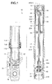
FIG. 1] Fig. 1 is a general cross-sectional view showing a hydraulic shock absorber. - [
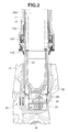
FIG. 2] Fig. 2 is a cross-sectional view of a lower portion inFig. 1 . - [
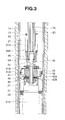
FIG. 3] Fig. 3 is a cross-sectional view of an intermediate portion inFig.1 . - [
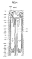
FIG. 4] Fig. 4 is a cross-sectional view of an upper portion inFig. 1 . - [
FIG. 5] Fig. 5 is a plan view showing a cap. - [
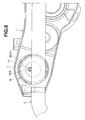
FIG. 6] Fig. 6 is a cross-sectional view showing a regulating portion provided in the cap. - [
FIG. 7] Fig. 7 is a cross-sectional view showing a modified embodiment of the regulating portion. - [
FIG. 8] Fig. 8 is a plan view showing a positional relationship between the regulating portion provided in the cap and a handle bar. - A front fork (a hydraulic shock absorber) 10 is an inverted type front fork in which an
outer tube 11 is arranged in a vehicle body side and aninner tube 12 is arranged in a wheel side, and as shown inFigs. 1 to 4 , theinner tube 12 is slidably inserted into an inner portion of theouter tube 11, via aguide bush 11A which is fixed to an inner periphery of a lower end opening portion of theouter tube 11 and aguide bush 12A which is fixed to an outer periphery of an upper end opening portion of theinner tube 12.Reference symbol 11B denotes an oil seal, andreference symbol 11C denotes a dust seal. Acap 13 is threadably attached to an upper end opening portion of theouter tube 11 coaxially in a liquid-tight manner so as to be sealed, and a vehicle body side bracket 1 (Fig. 8 ) is provided in an outer periphery of theouter tube 11. Anaxle bracket 15 is inserted and attached threadably in a liquid-tight manner into a lower end opening portion of theinner tube 12 so as to constitute a bottom portion of theinner tube 12, and anaxle attaching hole 16 is provided in theaxle bracket 15. - The
front fork 10 divides anannular oil chamber 17 which is divided by an inner periphery of theouter tube 11, an outer periphery of theinner tube 12, and the twoguide bushes - The
front fork 10 is provided with a closed-end cup-shapedpartition wall member 19 in an inner periphery close to an upper end of theinner tube 12 so as to be in a liquid-tight manner via an O-ring or the like, divides a workingoil chamber 21 in a lower portion of arod guide portion 19A in a bottom portion of thepartition wall member 19, and divides an oil reservoir chamber 22 m an upper portion. In theoil reservoir chamber 22, a lower region thereof is anoil chamber 22A, and an upper region thereof is anair chamber 22B. Theguide bush 12A provided in an outer periphery of an upper end portion protruding out of theinner tube 12 of thepartition wall member 19 comes into slidable contact with the inner periphery of theouter tube 11. - The
front fork 10 slidably inserts apiston rod 23 attached onto a center axis of theouter tube 11 into therod guide portion 19A of thepartition wall member 19. Specifically, thehollow piston rod 23 is threadably attached to an attachingcollar 24 which is coaxially and threadably attached to a lower end portion of a center portion of thecap 13, and is fixed by alock nut 24A. - The
front fork 10 is structured such that apiston 26 which comes into slidable contact with an inner periphery of theinner tube 12 is fixed to apiston bolt 25 which is threadably attached to a leading end portion of thepiston rod 23 inserted into theinner tube 12 from therod guide portion 19A of thepartition wall member 19, and theoil chamber 21 is divided into a piston rodside oil chamber 21A in which thepiston rod 23 is accommodated, and a pistonside oil chamber 21B in which thepiston rod 23 is not accommodated. Thepiston 26 is fixed by apiston nut 27. - The
front fork 10 is structured such that theannular oil chamber 17 is always communicated with the piston rodside oil chamber 21A via anoil hole 28 provided in theinner tube 12. - The
front fork 10 is structured such that anupper spring receiver 31 is attached to a side of a lower end surface which faces the pistonside oil chamber 21B of thepiston 26, alower spring receiver 32 is arranged in a bottom portion of theinner tube 12 formed by theaxle bracket 15, and amain suspension spring 33 is interposed between theupper spring receiver 31 and thelower spring receiver 32. A whole of themain suspension spring 33 is immersed into the pistonside oil chamber 21B. Thefront fork 10 absorbs an impact force applied from a road surface at a time when a vehicle travels, by means of an extension/retraction vibration of themain suspension spring 33. At this time, a springload regulating apparatus 35 moves up and down thelower spring receiver 32, making it possible to regulate a spring load of themain suspension spring 33. - The spring
load regulating apparatus 35 is provided with anadjust bolt 36 which faces outside at a position deviating from theaxle attaching hole 16 of the axle bracket 15 (in the side vicinity of the axle attaching hole 16) constituting a bottom portion of theinner tube 12, in the bottom portion, as shown inFig. 2 . Aslider 37 which is provided in an inner bottom portion of the axle bracket 15 (a face which is going to face a lower end portion of the lower spring receiver 32) is made movable linearly in a direction which intersects a center axis of the inner tube 12 (an axial direction of the adjust bolt 36) by a rotating force of theadjust bolt 36. The spring load of themain suspension spring 33 is regulated by mounting a lower inclined surface A1 of alifter 38 on which thelower spring receiver 32 seats on an upper inclined surface A2 of aslider 37, and moving up and down thelower spring receiver 32 by a rotation of theadjust bolt 36. - The
front fork 10 is provided with a dampingforce generating apparatus 40 in the piston 26 (Figs. 3 and4 ).
The dampingforce generating apparatus 40 is provided with a compressionside flow path 41 and an extension side flow path 42. The compressionside flow path 41 is opened and closed by a compression side disc valve 41A (a compression side damping valve) which is backed up by a valve stopper 41B. The extension side flow path 42 is opened and closed by an extensionside disc valve 42A (an extension side damping valve) which is backed up by avalve stopper 42B. In this case, the valve stopper 41B, the valve 41A, thepiston 26, thevalve 42A and thevalve stopper 42B constitute a valve assembly which is inserted and attached into thepiston bolt 25, and are sandwiched by apiston nut 27 which is threadably attached to thepiston bolt 25 so as to be fixed. - The damping
force generating apparatus 40 is structured such that a dampingforce regulating apparatus 40A mentioned in detail later is provided in a center portion of thecap 13, aneedle valve 85 of the dampingforce regulating apparatus 40A is inserted into a hollow portion of thepiston rod 23, and an opening degree of abypass path 45 provided in thepiston rod 23 is regulated by an upward and downward motion of theneedle valve 85. Thebypass path 45 bypasses thepiston 26, and communicates the piston rodside oil chamber 21A and the pistonside oil chamber 21B. - The damping
force generating apparatus 40 generates a compression side damping force by a passage resistance of thebypass path 45 whose opening degree is regulated by theneedle valve 85 in a low speed region, and generates a compression side damping force by a deflecting deformation of the compression side disc valve 41A in middle and high speed regions, in a compression side stroke. Further, the dampingforce generating apparatus 40 generates an extension side damping force by a passage resistance of thebypass path 45 whose opening degree is regulated by theneedle valve 85 in a low speed region, and generates an extension side damping force by a deflecting deformation of the extensionside disc valve 42A in middle and high speed regions, in an extension side stroke. The extension/retraction vibration of themain suspension spring 33 mentioned above is restrained by the compression side damping force and the extension side damping force. - The
front fork 10 is provided in a lower end surface of thecap 13 with astopper rubber 13A and astopper plate 13B with which an upper end portion of thepartition wall member 19 provided in theinner tube 12 comes into contact at a maximum compression stroke, and the maximum compression stroke is regulated by thisstopper rubber 13A. - The
front fork 10 is structured such that arebound spring 53 is interposed between a spring sheet 52 which is fixed to a lower end surface facing the piston rodside oil chamber 21A of thepartition wall member 19 in the upper end side of theinner tube 12 by using astopper ring 51A, and an upper end surface of thepiston bolt 25. Thepiston bolt 25 pressurizes therebound spring 53 with respect to the spring sheet 52 at a time of a maximum extension of thefront fork 10, thereby regulating a maximum extension stroke. - Accordingly, in the
front fork 10, a cross-sectional area S1 of theannular oil chamber 17 constituted by an annular gap of theouter tube 11 and theinner tube 12 is formed larger than a cross-sectional area (an area surrounded by an outer diameter) S2 of the piston rod 23 (S1 > S2). - Further, the
rod guide portion 19A of thepartition wall member 19 and thespring sheet 51 are provided with acheck valve 60 which allows an oil flow from theoil reservoir chamber 22 to the piston rodside oil chamber 21A in the compression side stroke, and blocks the oil flow from the piston rodside oil chamber 21A to theoil reservoir chamber 22 in the extension side stroke. - Further, since an oil seal is not sealed around the
piston rod 23 in therod guide portion 19A of thepartition wall member 19, a small flow path (an orifice) 61 which communicates the piston rodside oil chamber 21A and theoil reservoir chamber 22 is constituted by a small gap which a bush pressed into an inner periphery of thecheck valve 60 forms around thepiston rod 23. Thesmall flow path 61 is pierced in therod guide portion 19A of thepartition wall member 19, and is constituted by an orifice means which communicates the piston rodside oil chamber 21A and theoil reservoir chamber 22. - A working oil at a forward moving volumetric capacity of the
piston rod 23 which goes into theinner tube 12 at the compression side stroke is transferred to theannular oil chamber 17 from theoil chamber 21A in an inner periphery of theinner tube 12 via anoil hole 28 of theinner tube 12. At this time, since a volumetric capacity increment ΔS1 (an amount of replenishment) of theannular oil chamber 17 is larger than a volumetric capacity increment ΔS2 of thepiston rod 23, a shortfall (ΔS1 - ΔS2) in a necessary amount of replenishment of the oil to theannular oil chamber 17 is replenished via thecheck valve 60 from theoil reservoir chamber 22. - In this compression side stroke, as mentioned above, the compression side damping force is generated by the passage resistance of the
bypass path 45 whose opening degree is regulated by theneedle valve 85 in the low speed region, and the compression side damping force is generated by the deflecting deformation of the compression side disc valve 41A in the middle and high speed regions. - The working oil at a backward moving volumetric capacity of the
piston rod 23 which goes out of theinner tube 12 at the extension side stroke is transferred to theoil chamber 21A in the inner periphery of theinner tube 12 from theannular oil chamber 17 via theoil hole 28 of theinner tube 12. At this time, since a volumetric capacity decrement ΔS1 (an amount of discharge) of theannular oil chamber 17 is larger than a volumetric capacity decrement ΔS2 of thepiston rod 23, a surplus (ΔS1 - ΔS2) in the amount of oil discharged from theannular oil chamber 17 is discharged to theoil reservoir chamber 22 via thesmall flow path 61. - In this extension side stroke, as mentioned above, the extension side damping force is generated by the passage resistance of the
bypass path 45 whose opening degree is regulated by theneedle valve 85 in the low speed region, and the extension side damping force is generated by the deflecting deformation of the extensionside disc valve 42A in the middle and high speed regions. Further, the extension side damping force is also generated by a passage resistance of thesmall flow path 61 mentioned above. - The damping
force regulating apparatus 40A is structured, as shown inFigs. 3 and4 , such that a push rod 71 (a damping force regulating rod) is inserted into a hollow portion of thepiston rod 23 which is provided on a center axis of theouter tube 11 and thecap 13, and a regulatingportion 80 moving thepush rod 71 in an axial direction is provided in thecap 13 corresponding to an upper portion of thefront fork 10. - The regulating
portion 80 regulates the damping force generated by the passage resistance of thebypass path 45 by moving theneedle valve 85. A description will be given below of a structure of the regulatingportion 80 and a damping force regulating structure using theneedle valve 85. - The attaching
collar 24 is threadably attached to the lower end opening side of thecap 13, whereby acap assembly 100 is constituted. Thecap 13 of thecap assembly 100 is threadably attached in a liquid-tight manner to an upper end opening portion of theouter tube 11 via an O-ring 101, and an upper end portion of thepiston rod 23 is threadably attached to a lower end portion of the attachingcollar 24 so as to be fixed by thelock nut 24A. Thestopper rubber 13A is loaded to an annular concave portion formed by thecap 13 of thecap assembly 100 and the attachingcollar 24, and thestopper plate 13B is inserted and attached into an outer periphery of the attachingcollar 24, and astopper ring 13C locking thestopper plate 13B is locked and attached thereto (Fig. 6 ). - An adjust
assembly 110 is loaded to thecap 13 of thecap assembly 100 and the attachingcollar 24. The adjustassembly 110 constitute the regulatingportion 80 by an adjustbolt 81, and has an adjustnut 82 corresponding to the adjustbolt 81. The adjustnut 82 is fitted into the attachingcollar 24, and is provided at an eccentric position with respect to the center axis of the adjustnut 82 with athread hole 82A with which athread portion 81A of the adjustbolt 81 is threadably engaged. Accordingly, the adjustnut 82, with which the adjustbolt 81 is threadably engaged, moves up and down in an axial direction by a rotating operation of the adjustbolt 81, by being guided in the axial direction with rotation preventing state via an engagement with the inner periphery of the attachingcollar 24. - The adjust
bolt 81 of the regulatingportion 80 constituting the adjustassembly 110 is inserted and attached in a liquid-tight manner into a loading hole which is eccentrically arranged with respect to the center of thecap 13 via an O-ring 83 from a back surface side of thecap 13, in a plan view of thecap 13 constituting thecap assembly 100. Further, the adjustbolt 81 is stored in a centerconcave portion 102 of thecap assembly 100 formed by the attachingcollar 24 threadably attached to thecap 13, together with the adjustnut 82, aflange portion 81C of the adjustbolt 81 is brought into contact with the lower surface of thecap 13, and a lower end surface of the adjustbolt 81 is brought close to a bottom surface of the centerconcave portion 102 formed by the attachingcollar 24. The adjustnut 82 is slidably stored in an inner periphery of the centerconcave portion 102 formed by the attachingcollar 24. Thepush rod 71 protruding out of the hollow portion of thepiston rod 23 is brought into contact with the lower end surface of the adjustnut 82. - Accordingly, an upper
end operation portion 80A of the adjustbolt 81 of the regulatingportion 80 is arranged in a level which is flush with the upper surface of thecap 13, at a position deviating from the center of thecap 13 in a plan view of thecap 13 constituting thecap assembly 100. Further, the adjustbolt 81 of the regulatingportion 80 is pivoted to thecap 13 in such a manner as to only rotate and be immovable in the axial direction. Accordingly, if the adjustbolt 81 of the regulatingportion 80 is rotationally operated, the adjustnut 82 with which the adjustbolt 81 is threadably engaged moves up and down in the axial direction, and it is possible to move thepush rod 71 which is brought into contact with the adjustnut 82, in the axial direction. - An
inner base 84 is inserted and attached into the lower end portion of the hollow portion of thepiston rod 23, and the lower end surface of thepiston rod 23 and an inner diameter step portion of thepiston bolt 25 fix a lower end flange of theinner base 84 in a pinching manner. Theinner base 84 may be pressed into the hollow portion of thepiston rod 23. Theneedle valve 85 is inserted in a liquid-tight manner into the inner periphery of theinner base 84 which is fixed to thepiston rod 23 as mentioned above, and aspring 86 interposed between anintermediate flange position 85A of theneedle valve 85 and an upper end surface of theinner base 84 energizes theneedle valve 85 upward in the axial direction (in a valve opening direction), and brings the upper end surface of theneedle valve 85 into contact with the lower end surface of thepush rod 71. - If the adjust
bolt 81 of the regulatingportion 80 moves up and down thepush rod 71 in the axial direction as mentioned above, theneedle valve 85 coming into contact with thepush rod 71 in the axial direction moves up and down with respect to thepiston bolt 25, moves forward and backward with respect to a valve seat in an upper end portion of a vertical hole of thebypass path 45 provided in thepiston bolt 25, regulates the opening degree of thebypass path 45, and further can regulate the damping forces in the compression side and the extension side generated by the passage resistance of thebypass path 45. -
Fig. 7 is a modified embodiment of the regulatingportion 80. The regulatingportion 80 is structured, as shown inFig. 7 , such that aguide hole 90A is provided at an eccentric position with respect to the center axis of the adjust nut 82 (a different eccentric position from thethread hole 82A), as the adjustassembly 110 loaded to thecap assembly 100, arotation preventing pin 90 is inserted into theguide hole 90A, an upper end portion of therotation preventing pin 90 is fixedly inserted into an attaching hole provided in thecap 13, and a lower end portion of therotation preventing pin 90 is brought close to a bottom surface of the centerconcave portion 102 of the attachingcollar 24. It is possible to achieve a high precision of the rotation prevention of the adjustnut 82 by therotation preventing pin 90, and it is further possible to make an axial moving precision of thepush rod 71 with respect to an angle of rotation of the adjustbolt 81 high. -
Fig. 8 shows a structure in which the right and leftfront forks 10 are attached to the vehiclebody side bracket 1 of the motor cycle (a right side is omitted inFig. 8 ), and ahandle bar 2 is retained in the upper portion of the vehiclebody side bracket 1. In a plan view of the vehiclebody side bracket 1, the regulatingportion 80 provided in thecap 13 of thefront fork 10 is not obstructed by thehandle bar 2, and a rider can smoothly operate the regulatingportion 80 from an upper surface of thehandle bar 2. - According to the present embodiment, the following operations and effects can be achieved.
- (a) Since the regulating
portion 80 is arranged eccentrically with respect to the center of thecap 13 in a plan view of thecap 13, the operation of the regulatingportion 80 by the rider is not obstructed by thehandle bar 2, it is possible to improve the operability of the regulatingportion 80 and it is possible to provide a new outer appearance. -
- (b) Since the regulating
portion 80 is pivoted to thecap 13 so as to only rotate and be immovable in the axial direction, the regulatingportion 80 does not move upward by the rotating operation, it is possible to suppress a height, and it is possible to improve an exterior appearance as products. -
- (c) When the adjust
bolt 81 constituting the regulatingportion 80 moves the adjustnut 82, the attachingcollar 24 is utilized, and the adjustnut 82 can be moved and guided in the axial direction while prevented from rotation. A rotation preventing part and a guide part for the adjustnut 82 are not separately required. - As heretofore explained, embodiments of the present invention have been described in detail with reference to the drawings. However, the specific configurations of the present invention are not limited to the illustrated embodiments but those having a modification of the design within the range of the presently claimed invention are also included in the present invention.
- The present invention is structured such that the regulating portion is arranged eccentrically with respect to the center of the cap in the plan view of the cap, in the hydraulic shock absorber in which the vehicle body side tube and the axle side tube are slidably fitted, and the single regulating portion is provided in the cap which is sealed to the upper end opening portion of the vehicle body side tube. Accordingly, it is possible to improve the operability of the regulating portion and to provide the new outer appearance.
-
- 10
- front fork (hydraulic shock absorber)
- 11
- outer tube (vehicle body side tube)
- 12
- inner tube (axle side tube)
- 13
- cap
- 19
- partition wall member
- 21
- working oil chamber
- 21A
- piston rod side oil chamber
- 21B
- piston side oil chamber
- 22
- oil reservoir chamber
- 23
- piston rod (piston support member)
- 24
- attaching collar
- 26
- piston
- 41
- compression side flow path
- 41A
- compression side disc valve (compression side damping valve)
- 42
- extension side flow path
- 42A
- extension side disc valve (extension side damping valve)
- 45
- bypass path
- 80
- regulating portion
- 81
- adjust bolt
- 82
- adjust nut
- 82A
- thread hole
- 85
- needle valve
Claims (8)
- A hydraulic shock absorber comprising:a vehicle body side tube;an axle side tube, the vehicle body side tube and the axle side tube being slidably fitted;a cap sealed to an upper end opening portion of the vehicle body side tube;anda single regulating portion provided in the cap,wherein the regulating portion is arranged eccentrically with respect to a center of the cap in a plan view of the cap.
- A hydraulic shock absorber comprising:an outer tube in a vehicle body side;an inner tube in an axle side, the inner tube being slidably inserted into the outer tube;a partition wall member provided in an inner periphery of the inner tube;a working oil chamber being sectioned below of the partition wall member;an oil reservoir chamber being sectioned above the partition wall member;a piston support member attached to the outer tube side, the piston support member being inverted into the working oil chamber through the partition wall member;a piston sliding within the working oil chamber, the piston being provided in a leading end portion of the piston support member;a cap sealed to an upper end opening portion of the outer tube; anda single regulating portion provided in the cap,wherein the regulating portion is arranged eccentrically with respect to a center of the cap, in a plan view of the cap.
- A hydraulic shock absorber comprising:an outer tube in a vehicle body side;an inner tube in an axle side, the inner tube being slidably inserted into the outer tube;a partition wall member provided in an inner periphery of the inner tube;a working oil chamber being sectioned below the partition wall member;an oil reservoir chamber being sectioned above the partition wall member;a hollow piston rod attached to the outer tube side, the hollow piston rod being inserted into the working oil chamber through the partition wall member;a piston sliding within the working oil chamber, the piston being provided in a leading end portion of the piston rod;the working oil chamber of the inner tube being divided into a piston rod side oil chamber and a piston side oil chamber by the piston;these two oil chambers being capable of being communicated respectively by a compression side flow path and an extension side flow path provided in the piston;a compression side damping valve being provided in an outlet of the compression side flow path, and an extension side damping valve being provided in an outlet of the extension side flow path;a bypass path communicating the piston rod side oil chamber and the piston side oil chamber, the bypass path being provided in a hollow portion of the piston rod;a needle valve provided in the bypass path;a cap sealed to an upper end opening portion of the outer tube; anda regulating portion regulating a damping force generated by a passage resistance of the bypass path by moving the needle valve, the regulating portion being provided in the cap,wherein the regulating portion is arranged eccentrically with respect to a center of the cap, in a plan view of the cap.
- The hydraulic shock absorber according to any one of claims 1 to 3, wherein the regulating portion is pivoted to the cap so as to only rotate and be immovable in an axial direction.
- The hydraulic shock absorber according to claim 4, wherein the regulating portion consists of an adjust bolt, and accessorily has an adjust nut corresponding to the adjust bolt,
the adjust nut is provided with a thread hole with which the adjust bolt is threadably engaged, the adjust nut being fitted into an attaching collar which is fixed coaxially to the cap, and
the adjust nut with which the adjust bolt is threadably engaged is structured so as to move in an axial direction by a rotating operation of the adjust bolt, by being guided to move in the axial direction with rotation preventing state via an engagement with an inner periphery of the attaching collar. - The hydraulic shock absorber according to claim 5, wherein the cap consists of a cap assembly in which the attaching collar is threadably attached to a lower end opening side, and the adjust bolt consists of an adjust assembly with which the adjust nut is threadably engaged.
- The hydraulic shock absorber according to claim 6, wherein an upper end operation portion of the adjust bolt is arranged in a level which is flush with an upper surface of the cap, at a position deviating from a center of the cap, in a plan view of the cap constructing the cap assembly.
- The hydraulic shock absorber according to claim 6 or 7, wherein the regulating portion is structured such that a guide hole is provided at a different eccentric position from the thread hole, with respect to a center axis of the adjust nut, as an adjust assembly loaded to the cap assembly, a rotation preventing pin is inserted into the guide hole, an upper end portion of the rotation preventing pin is fixedly inserted into an attaching hole provided in the cap, and a lower end portion of the rotation preventing pin is brought close to a bottom surface of a center concave portion of the attaching collar.
Applications Claiming Priority (2)
| Application Number | Priority Date | Filing Date | Title |
|---|---|---|---|
| JP2009074615A JP5660653B2 (en) | 2009-03-25 | 2009-03-25 | Hydraulic shock absorber |
| PCT/JP2009/066411 WO2010109697A1 (en) | 2009-03-25 | 2009-09-18 | Hydraulic buffer |
Publications (3)
| Publication Number | Publication Date |
|---|---|
| EP2413003A1 true EP2413003A1 (en) | 2012-02-01 |
| EP2413003A4 EP2413003A4 (en) | 2017-10-18 |
| EP2413003B1 EP2413003B1 (en) | 2019-11-06 |
Family
ID=42780402
Family Applications (1)
| Application Number | Title | Priority Date | Filing Date |
|---|---|---|---|
| EP09842307.2A Active EP2413003B1 (en) | 2009-03-25 | 2009-09-18 | Hydraulic shock absorber |
Country Status (3)
| Country | Link |
|---|---|
| EP (1) | EP2413003B1 (en) |
| JP (1) | JP5660653B2 (en) |
| WO (1) | WO2010109697A1 (en) |
Cited By (1)
| Publication number | Priority date | Publication date | Assignee | Title |
|---|---|---|---|---|
| US10876590B2 (en) | 2015-06-17 | 2020-12-29 | Showa Corporation | Damping force variable shock absorber |
Families Citing this family (5)
| Publication number | Priority date | Publication date | Assignee | Title |
|---|---|---|---|---|
| US8963131B2 (en) * | 2011-06-13 | 2015-02-24 | Samsung Electronics Co., Ltd. | Electronic device |
| JP2013108580A (en) * | 2011-11-22 | 2013-06-06 | Kyb Co Ltd | Damping valve |
| JP2014005864A (en) * | 2012-06-22 | 2014-01-16 | Showa Corp | Front fork device |
| JP6462470B2 (en) * | 2015-04-20 | 2019-01-30 | Kybモーターサイクルサスペンション株式会社 | Front fork |
| JP6524329B1 (en) * | 2018-12-20 | 2019-06-05 | 株式会社ショーワ | Hydraulic shock absorber and straddle type vehicle |
Family Cites Families (12)
| Publication number | Priority date | Publication date | Assignee | Title |
|---|---|---|---|---|
| US4305486A (en) * | 1979-10-11 | 1981-12-15 | Interpart Corporation | Dual damping control valve shock absorber |
| US4440273A (en) * | 1981-12-28 | 1984-04-03 | Halliburton Company | Aeration preventing shock absorber |
| JPH0447459Y2 (en) * | 1985-10-30 | 1992-11-10 | ||
| JPS6320544U (en) * | 1986-07-25 | 1988-02-10 | ||
| JP2849882B2 (en) * | 1992-02-24 | 1999-01-27 | 株式会社ナブコ | Prosthetic cylinder |
| JPH06234386A (en) * | 1992-12-16 | 1994-08-23 | Suzuki Motor Corp | Damping force adjusting device for motorcycle suspension |
| US6840357B2 (en) * | 2002-07-18 | 2005-01-11 | Bombardier Inc. | Hydraulic damping device |
| JP4358546B2 (en) * | 2003-04-14 | 2009-11-04 | 株式会社ショーワ | Damping force adjustment device for hydraulic shock absorber |
| JP4268843B2 (en) * | 2003-07-10 | 2009-05-27 | カヤバ工業株式会社 | Front fork |
| JP4554998B2 (en) * | 2004-06-14 | 2010-09-29 | カヤバ工業株式会社 | Operation dial |
| JP4700519B2 (en) | 2006-02-24 | 2011-06-15 | 株式会社ショーワ | Front fork damping force adjustment device |
| JP4723611B2 (en) * | 2008-04-28 | 2011-07-13 | 株式会社ショーワ | Hydraulic shock absorber |
-
2009
- 2009-03-25 JP JP2009074615A patent/JP5660653B2/en active Active
- 2009-09-18 EP EP09842307.2A patent/EP2413003B1/en active Active
- 2009-09-18 WO PCT/JP2009/066411 patent/WO2010109697A1/en not_active Ceased
Non-Patent Citations (1)
| Title |
|---|
| See references of WO2010109697A1 * |
Cited By (1)
| Publication number | Priority date | Publication date | Assignee | Title |
|---|---|---|---|---|
| US10876590B2 (en) | 2015-06-17 | 2020-12-29 | Showa Corporation | Damping force variable shock absorber |
Also Published As
| Publication number | Publication date |
|---|---|
| WO2010109697A1 (en) | 2010-09-30 |
| JP5660653B2 (en) | 2015-01-28 |
| JP2010223413A (en) | 2010-10-07 |
| EP2413003A4 (en) | 2017-10-18 |
| EP2413003B1 (en) | 2019-11-06 |
Similar Documents
| Publication | Publication Date | Title |
|---|---|---|
| EP2584215B1 (en) | Hydraulic damper | |
| EP2413003B1 (en) | Hydraulic shock absorber | |
| EP2330314B1 (en) | Front fork | |
| US9284014B2 (en) | Damper | |
| CN102859227B (en) | Extension Control Valve For Hydraulic Damper | |
| JP5452434B2 (en) | Front fork | |
| EP2783967A2 (en) | Hydraulic shock absorber | |
| US20100148412A1 (en) | Hydraulic shock absorber | |
| US20110024957A1 (en) | Vehicle height adjusting apparatus | |
| EP1826453A1 (en) | Damping force adjusting apparatus of front fork | |
| US20080053764A1 (en) | Front fork | |
| US8641022B2 (en) | Front fork | |
| US6412615B1 (en) | Hydraulic shock absorber for motor vehicles | |
| EP2743537A1 (en) | Damper with vehicle height adjusting function | |
| EP2740965A1 (en) | Damper | |
| US20090107785A1 (en) | Hydraulic shock absorber | |
| JP2009108884A (en) | Hydraulic shock absorber | |
| EP1884397B1 (en) | Hydraulic shock absorber | |
| JP2013199351A (en) | Lift cylinder and forklift with the same | |
| JP4965490B2 (en) | Hydraulic shock absorber | |
| JP2010096222A (en) | Vehicular hydraulic shock absorber | |
| JP5905310B2 (en) | Hydraulic shock absorber | |
| JP5872347B2 (en) | Hydraulic shock absorber | |
| KR100736548B1 (en) | Garage Adjustable Shock Absorber | |
| EP1705396A1 (en) | Front fork of motorcycle |
Legal Events
| Date | Code | Title | Description |
|---|---|---|---|
| PUAI | Public reference made under article 153(3) epc to a published international application that has entered the european phase |
Free format text: ORIGINAL CODE: 0009012 |
|
| 17P | Request for examination filed |
Effective date: 20111025 |
|
| AK | Designated contracting states |
Kind code of ref document: A1 Designated state(s): AT BE BG CH CY CZ DE DK EE ES FI FR GB GR HR HU IE IS IT LI LT LU LV MC MK MT NL NO PL PT RO SE SI SK SM TR |
|
| DAX | Request for extension of the european patent (deleted) | ||
| RA4 | Supplementary search report drawn up and despatched (corrected) |
Effective date: 20170918 |
|
| RIC1 | Information provided on ipc code assigned before grant |
Ipc: F16F 9/44 20060101AFI20170912BHEP Ipc: F16F 9/32 20060101ALI20170912BHEP |
|
| STAA | Information on the status of an ep patent application or granted ep patent |
Free format text: STATUS: EXAMINATION IS IN PROGRESS |
|
| 17Q | First examination report despatched |
Effective date: 20180618 |
|
| GRAP | Despatch of communication of intention to grant a patent |
Free format text: ORIGINAL CODE: EPIDOSNIGR1 |
|
| RIN1 | Information on inventor provided before grant (corrected) |
Inventor name: MURAKAMI, YOSUKE |
|
| STAA | Information on the status of an ep patent application or granted ep patent |
Free format text: STATUS: GRANT OF PATENT IS INTENDED |
|
| INTG | Intention to grant announced |
Effective date: 20190103 |
|
| GRAS | Grant fee paid |
Free format text: ORIGINAL CODE: EPIDOSNIGR3 |
|
| GRAJ | Information related to disapproval of communication of intention to grant by the applicant or resumption of examination proceedings by the epo deleted |
Free format text: ORIGINAL CODE: EPIDOSDIGR1 |
|
| GRAL | Information related to payment of fee for publishing/printing deleted |
Free format text: ORIGINAL CODE: EPIDOSDIGR3 |
|
| STAA | Information on the status of an ep patent application or granted ep patent |
Free format text: STATUS: EXAMINATION IS IN PROGRESS |
|
| GRAP | Despatch of communication of intention to grant a patent |
Free format text: ORIGINAL CODE: EPIDOSNIGR1 |
|
| STAA | Information on the status of an ep patent application or granted ep patent |
Free format text: STATUS: GRANT OF PATENT IS INTENDED |
|
| INTC | Intention to grant announced (deleted) | ||
| INTG | Intention to grant announced |
Effective date: 20190604 |
|
| GRAA | (expected) grant |
Free format text: ORIGINAL CODE: 0009210 |
|
| STAA | Information on the status of an ep patent application or granted ep patent |
Free format text: STATUS: THE PATENT HAS BEEN GRANTED |
|
| AK | Designated contracting states |
Kind code of ref document: B1 Designated state(s): AT BE BG CH CY CZ DE DK EE ES FI FR GB GR HR HU IE IS IT LI LT LU LV MC MK MT NL NO PL PT RO SE SI SK SM TR |
|
| REG | Reference to a national code |
Ref country code: GB Ref legal event code: FG4D |
|
| REG | Reference to a national code |
Ref country code: CH Ref legal event code: EP Ref country code: AT Ref legal event code: REF Ref document number: 1199133 Country of ref document: AT Kind code of ref document: T Effective date: 20191115 |
|
| REG | Reference to a national code |
Ref country code: IE Ref legal event code: FG4D |
|
| REG | Reference to a national code |
Ref country code: DE Ref legal event code: R096 Ref document number: 602009060396 Country of ref document: DE |
|
| REG | Reference to a national code |
Ref country code: NL Ref legal event code: MP Effective date: 20191106 |
|
| REG | Reference to a national code |
Ref country code: LT Ref legal event code: MG4D |
|
| PG25 | Lapsed in a contracting state [announced via postgrant information from national office to epo] |
Ref country code: FI Free format text: LAPSE BECAUSE OF FAILURE TO SUBMIT A TRANSLATION OF THE DESCRIPTION OR TO PAY THE FEE WITHIN THE PRESCRIBED TIME-LIMIT Effective date: 20191106 Ref country code: GR Free format text: LAPSE BECAUSE OF FAILURE TO SUBMIT A TRANSLATION OF THE DESCRIPTION OR TO PAY THE FEE WITHIN THE PRESCRIBED TIME-LIMIT Effective date: 20200207 Ref country code: LT Free format text: LAPSE BECAUSE OF FAILURE TO SUBMIT A TRANSLATION OF THE DESCRIPTION OR TO PAY THE FEE WITHIN THE PRESCRIBED TIME-LIMIT Effective date: 20191106 Ref country code: NL Free format text: LAPSE BECAUSE OF FAILURE TO SUBMIT A TRANSLATION OF THE DESCRIPTION OR TO PAY THE FEE WITHIN THE PRESCRIBED TIME-LIMIT Effective date: 20191106 Ref country code: ES Free format text: LAPSE BECAUSE OF FAILURE TO SUBMIT A TRANSLATION OF THE DESCRIPTION OR TO PAY THE FEE WITHIN THE PRESCRIBED TIME-LIMIT Effective date: 20191106 Ref country code: PL Free format text: LAPSE BECAUSE OF FAILURE TO SUBMIT A TRANSLATION OF THE DESCRIPTION OR TO PAY THE FEE WITHIN THE PRESCRIBED TIME-LIMIT Effective date: 20191106 Ref country code: NO Free format text: LAPSE BECAUSE OF FAILURE TO SUBMIT A TRANSLATION OF THE DESCRIPTION OR TO PAY THE FEE WITHIN THE PRESCRIBED TIME-LIMIT Effective date: 20200206 Ref country code: PT Free format text: LAPSE BECAUSE OF FAILURE TO SUBMIT A TRANSLATION OF THE DESCRIPTION OR TO PAY THE FEE WITHIN THE PRESCRIBED TIME-LIMIT Effective date: 20200306 Ref country code: BG Free format text: LAPSE BECAUSE OF FAILURE TO SUBMIT A TRANSLATION OF THE DESCRIPTION OR TO PAY THE FEE WITHIN THE PRESCRIBED TIME-LIMIT Effective date: 20200206 Ref country code: LV Free format text: LAPSE BECAUSE OF FAILURE TO SUBMIT A TRANSLATION OF THE DESCRIPTION OR TO PAY THE FEE WITHIN THE PRESCRIBED TIME-LIMIT Effective date: 20191106 Ref country code: SE Free format text: LAPSE BECAUSE OF FAILURE TO SUBMIT A TRANSLATION OF THE DESCRIPTION OR TO PAY THE FEE WITHIN THE PRESCRIBED TIME-LIMIT Effective date: 20191106 |
|
| PG25 | Lapsed in a contracting state [announced via postgrant information from national office to epo] |
Ref country code: IS Free format text: LAPSE BECAUSE OF FAILURE TO SUBMIT A TRANSLATION OF THE DESCRIPTION OR TO PAY THE FEE WITHIN THE PRESCRIBED TIME-LIMIT Effective date: 20200306 Ref country code: HR Free format text: LAPSE BECAUSE OF FAILURE TO SUBMIT A TRANSLATION OF THE DESCRIPTION OR TO PAY THE FEE WITHIN THE PRESCRIBED TIME-LIMIT Effective date: 20191106 |
|
| PG25 | Lapsed in a contracting state [announced via postgrant information from national office to epo] |
Ref country code: DK Free format text: LAPSE BECAUSE OF FAILURE TO SUBMIT A TRANSLATION OF THE DESCRIPTION OR TO PAY THE FEE WITHIN THE PRESCRIBED TIME-LIMIT Effective date: 20191106 Ref country code: RO Free format text: LAPSE BECAUSE OF FAILURE TO SUBMIT A TRANSLATION OF THE DESCRIPTION OR TO PAY THE FEE WITHIN THE PRESCRIBED TIME-LIMIT Effective date: 20191106 Ref country code: CZ Free format text: LAPSE BECAUSE OF FAILURE TO SUBMIT A TRANSLATION OF THE DESCRIPTION OR TO PAY THE FEE WITHIN THE PRESCRIBED TIME-LIMIT Effective date: 20191106 Ref country code: EE Free format text: LAPSE BECAUSE OF FAILURE TO SUBMIT A TRANSLATION OF THE DESCRIPTION OR TO PAY THE FEE WITHIN THE PRESCRIBED TIME-LIMIT Effective date: 20191106 |
|
| REG | Reference to a national code |
Ref country code: DE Ref legal event code: R097 Ref document number: 602009060396 Country of ref document: DE |
|
| REG | Reference to a national code |
Ref country code: AT Ref legal event code: MK05 Ref document number: 1199133 Country of ref document: AT Kind code of ref document: T Effective date: 20191106 |
|
| PG25 | Lapsed in a contracting state [announced via postgrant information from national office to epo] |
Ref country code: SK Free format text: LAPSE BECAUSE OF FAILURE TO SUBMIT A TRANSLATION OF THE DESCRIPTION OR TO PAY THE FEE WITHIN THE PRESCRIBED TIME-LIMIT Effective date: 20191106 Ref country code: SM Free format text: LAPSE BECAUSE OF FAILURE TO SUBMIT A TRANSLATION OF THE DESCRIPTION OR TO PAY THE FEE WITHIN THE PRESCRIBED TIME-LIMIT Effective date: 20191106 |
|
| PLBE | No opposition filed within time limit |
Free format text: ORIGINAL CODE: 0009261 |
|
| STAA | Information on the status of an ep patent application or granted ep patent |
Free format text: STATUS: NO OPPOSITION FILED WITHIN TIME LIMIT |
|
| 26N | No opposition filed |
Effective date: 20200807 |
|
| PG25 | Lapsed in a contracting state [announced via postgrant information from national office to epo] |
Ref country code: SI Free format text: LAPSE BECAUSE OF FAILURE TO SUBMIT A TRANSLATION OF THE DESCRIPTION OR TO PAY THE FEE WITHIN THE PRESCRIBED TIME-LIMIT Effective date: 20191106 Ref country code: AT Free format text: LAPSE BECAUSE OF FAILURE TO SUBMIT A TRANSLATION OF THE DESCRIPTION OR TO PAY THE FEE WITHIN THE PRESCRIBED TIME-LIMIT Effective date: 20191106 |
|
| PG25 | Lapsed in a contracting state [announced via postgrant information from national office to epo] |
Ref country code: MC Free format text: LAPSE BECAUSE OF FAILURE TO SUBMIT A TRANSLATION OF THE DESCRIPTION OR TO PAY THE FEE WITHIN THE PRESCRIBED TIME-LIMIT Effective date: 20191106 |
|
| REG | Reference to a national code |
Ref country code: CH Ref legal event code: PL |
|
| REG | Reference to a national code |
Ref country code: BE Ref legal event code: MM Effective date: 20200930 |
|
| PG25 | Lapsed in a contracting state [announced via postgrant information from national office to epo] |
Ref country code: LU Free format text: LAPSE BECAUSE OF NON-PAYMENT OF DUE FEES Effective date: 20200918 |
|
| PG25 | Lapsed in a contracting state [announced via postgrant information from national office to epo] |
Ref country code: FR Free format text: LAPSE BECAUSE OF NON-PAYMENT OF DUE FEES Effective date: 20200930 |
|
| PG25 | Lapsed in a contracting state [announced via postgrant information from national office to epo] |
Ref country code: LI Free format text: LAPSE BECAUSE OF NON-PAYMENT OF DUE FEES Effective date: 20200930 Ref country code: IE Free format text: LAPSE BECAUSE OF NON-PAYMENT OF DUE FEES Effective date: 20200918 Ref country code: CH Free format text: LAPSE BECAUSE OF NON-PAYMENT OF DUE FEES Effective date: 20200930 Ref country code: BE Free format text: LAPSE BECAUSE OF NON-PAYMENT OF DUE FEES Effective date: 20200930 |
|
| REG | Reference to a national code |
Ref country code: DE Ref legal event code: R081 Ref document number: 602009060396 Country of ref document: DE Owner name: HITACHI ASTEMO, LTD., HITACHINAKA-SHI, JP Free format text: FORMER OWNER: SHOWA CORPORATION, GYODA-SHI, SAITAMA, JP Ref country code: GB Ref legal event code: 732E Free format text: REGISTERED BETWEEN 20211216 AND 20211222 |
|
| PG25 | Lapsed in a contracting state [announced via postgrant information from national office to epo] |
Ref country code: TR Free format text: LAPSE BECAUSE OF FAILURE TO SUBMIT A TRANSLATION OF THE DESCRIPTION OR TO PAY THE FEE WITHIN THE PRESCRIBED TIME-LIMIT Effective date: 20191106 Ref country code: MT Free format text: LAPSE BECAUSE OF FAILURE TO SUBMIT A TRANSLATION OF THE DESCRIPTION OR TO PAY THE FEE WITHIN THE PRESCRIBED TIME-LIMIT Effective date: 20191106 Ref country code: CY Free format text: LAPSE BECAUSE OF FAILURE TO SUBMIT A TRANSLATION OF THE DESCRIPTION OR TO PAY THE FEE WITHIN THE PRESCRIBED TIME-LIMIT Effective date: 20191106 |
|
| PG25 | Lapsed in a contracting state [announced via postgrant information from national office to epo] |
Ref country code: MK Free format text: LAPSE BECAUSE OF FAILURE TO SUBMIT A TRANSLATION OF THE DESCRIPTION OR TO PAY THE FEE WITHIN THE PRESCRIBED TIME-LIMIT Effective date: 20191106 |
|
| REG | Reference to a national code |
Ref country code: DE Ref legal event code: R082 Ref document number: 602009060396 Country of ref document: DE Representative=s name: MAUCHER JENKINS PATENTANWAELTE & RECHTSANWAELT, DE |
|
| PGFP | Annual fee paid to national office [announced via postgrant information from national office to epo] |
Ref country code: DE Payment date: 20250730 Year of fee payment: 17 |
|
| PGFP | Annual fee paid to national office [announced via postgrant information from national office to epo] |
Ref country code: IT Payment date: 20250825 Year of fee payment: 17 |
|
| PGFP | Annual fee paid to national office [announced via postgrant information from national office to epo] |
Ref country code: GB Payment date: 20250731 Year of fee payment: 17 |