EP2412957A2 - A fuel admission control unit to control a diesel engine - Google Patents
A fuel admission control unit to control a diesel engine Download PDFInfo
- Publication number
- EP2412957A2 EP2412957A2 EP20110186662 EP11186662A EP2412957A2 EP 2412957 A2 EP2412957 A2 EP 2412957A2 EP 20110186662 EP20110186662 EP 20110186662 EP 11186662 A EP11186662 A EP 11186662A EP 2412957 A2 EP2412957 A2 EP 2412957A2
- Authority
- EP
- European Patent Office
- Prior art keywords
- fuel
- excess air
- air ratio
- accelerator opening
- control unit
- Prior art date
- Legal status (The legal status is an assumption and is not a legal conclusion. Google has not performed a legal analysis and makes no representation as to the accuracy of the status listed.)
- Granted
Links
- 239000000446 fuel Substances 0.000 title claims abstract description 114
- 239000007789 gas Substances 0.000 claims abstract description 64
- QVGXLLKOCUKJST-UHFFFAOYSA-N atomic oxygen Chemical compound [O] QVGXLLKOCUKJST-UHFFFAOYSA-N 0.000 claims abstract description 54
- 239000001301 oxygen Substances 0.000 claims abstract description 54
- 229910052760 oxygen Inorganic materials 0.000 claims abstract description 54
- 238000002347 injection Methods 0.000 claims abstract description 29
- 239000007924 injection Substances 0.000 claims abstract description 29
- 230000001133 acceleration Effects 0.000 claims abstract description 19
- 230000008859 change Effects 0.000 claims description 44
- 239000000779 smoke Substances 0.000 claims description 32
- 230000004044 response Effects 0.000 abstract description 19
- MWUXSHHQAYIFBG-UHFFFAOYSA-N Nitric oxide Chemical compound O=[N] MWUXSHHQAYIFBG-UHFFFAOYSA-N 0.000 description 39
- 230000001276 controlling effect Effects 0.000 description 25
- 238000002485 combustion reaction Methods 0.000 description 18
- 238000000034 method Methods 0.000 description 12
- 230000009467 reduction Effects 0.000 description 9
- 238000010586 diagram Methods 0.000 description 8
- 230000006866 deterioration Effects 0.000 description 6
- 230000008569 process Effects 0.000 description 5
- 238000004364 calculation method Methods 0.000 description 4
- 238000012937 correction Methods 0.000 description 4
- 238000005516 engineering process Methods 0.000 description 4
- 230000007423 decrease Effects 0.000 description 3
- 238000005259 measurement Methods 0.000 description 3
- 230000000694 effects Effects 0.000 description 2
- 230000006872 improvement Effects 0.000 description 2
- 238000005070 sampling Methods 0.000 description 2
- 238000012360 testing method Methods 0.000 description 2
- 230000001052 transient effect Effects 0.000 description 2
- 238000011144 upstream manufacturing Methods 0.000 description 2
- 238000012795 verification Methods 0.000 description 2
- 230000009471 action Effects 0.000 description 1
- 238000000137 annealing Methods 0.000 description 1
- 230000003466 anti-cipated effect Effects 0.000 description 1
- 230000003247 decreasing effect Effects 0.000 description 1
- 238000002474 experimental method Methods 0.000 description 1
- 238000004519 manufacturing process Methods 0.000 description 1
- 239000000463 material Substances 0.000 description 1
- 230000007246 mechanism Effects 0.000 description 1
- 230000001105 regulatory effect Effects 0.000 description 1
- 229920006395 saturated elastomer Polymers 0.000 description 1
- 239000000243 solution Substances 0.000 description 1
Images


Classifications
-
- F—MECHANICAL ENGINEERING; LIGHTING; HEATING; WEAPONS; BLASTING
- F02—COMBUSTION ENGINES; HOT-GAS OR COMBUSTION-PRODUCT ENGINE PLANTS
- F02D—CONTROLLING COMBUSTION ENGINES
- F02D41/00—Electrical control of supply of combustible mixture or its constituents
- F02D41/0025—Controlling engines characterised by use of non-liquid fuels, pluralities of fuels, or non-fuel substances added to the combustible mixtures
- F02D41/0047—Controlling exhaust gas recirculation [EGR]
- F02D41/0065—Specific aspects of external EGR control
-
- F—MECHANICAL ENGINEERING; LIGHTING; HEATING; WEAPONS; BLASTING
- F02—COMBUSTION ENGINES; HOT-GAS OR COMBUSTION-PRODUCT ENGINE PLANTS
- F02D—CONTROLLING COMBUSTION ENGINES
- F02D41/00—Electrical control of supply of combustible mixture or its constituents
- F02D41/0002—Controlling intake air
-
- F—MECHANICAL ENGINEERING; LIGHTING; HEATING; WEAPONS; BLASTING
- F02—COMBUSTION ENGINES; HOT-GAS OR COMBUSTION-PRODUCT ENGINE PLANTS
- F02D—CONTROLLING COMBUSTION ENGINES
- F02D41/00—Electrical control of supply of combustible mixture or its constituents
- F02D41/02—Circuit arrangements for generating control signals
- F02D41/04—Introducing corrections for particular operating conditions
- F02D41/10—Introducing corrections for particular operating conditions for acceleration
-
- F—MECHANICAL ENGINEERING; LIGHTING; HEATING; WEAPONS; BLASTING
- F02—COMBUSTION ENGINES; HOT-GAS OR COMBUSTION-PRODUCT ENGINE PLANTS
- F02D—CONTROLLING COMBUSTION ENGINES
- F02D41/00—Electrical control of supply of combustible mixture or its constituents
- F02D41/02—Circuit arrangements for generating control signals
- F02D41/14—Introducing closed-loop corrections
- F02D41/1438—Introducing closed-loop corrections using means for determining characteristics of the combustion gases; Sensors therefor
- F02D41/1439—Introducing closed-loop corrections using means for determining characteristics of the combustion gases; Sensors therefor characterised by the position of the sensor
- F02D41/144—Sensor in intake manifold
-
- F—MECHANICAL ENGINEERING; LIGHTING; HEATING; WEAPONS; BLASTING
- F02—COMBUSTION ENGINES; HOT-GAS OR COMBUSTION-PRODUCT ENGINE PLANTS
- F02D—CONTROLLING COMBUSTION ENGINES
- F02D41/00—Electrical control of supply of combustible mixture or its constituents
- F02D41/02—Circuit arrangements for generating control signals
- F02D41/14—Introducing closed-loop corrections
- F02D41/1438—Introducing closed-loop corrections using means for determining characteristics of the combustion gases; Sensors therefor
- F02D41/1444—Introducing closed-loop corrections using means for determining characteristics of the combustion gases; Sensors therefor characterised by the characteristics of the combustion gases
- F02D41/1454—Introducing closed-loop corrections using means for determining characteristics of the combustion gases; Sensors therefor characterised by the characteristics of the combustion gases the characteristics being an oxygen content or concentration or the air-fuel ratio
- F02D41/1458—Introducing closed-loop corrections using means for determining characteristics of the combustion gases; Sensors therefor characterised by the characteristics of the combustion gases the characteristics being an oxygen content or concentration or the air-fuel ratio with determination means using an estimation
-
- F—MECHANICAL ENGINEERING; LIGHTING; HEATING; WEAPONS; BLASTING
- F02—COMBUSTION ENGINES; HOT-GAS OR COMBUSTION-PRODUCT ENGINE PLANTS
- F02D—CONTROLLING COMBUSTION ENGINES
- F02D2200/00—Input parameters for engine control
- F02D2200/02—Input parameters for engine control the parameters being related to the engine
- F02D2200/04—Engine intake system parameters
- F02D2200/0402—Engine intake system parameters the parameter being determined by using a model of the engine intake or its components
-
- F—MECHANICAL ENGINEERING; LIGHTING; HEATING; WEAPONS; BLASTING
- F02—COMBUSTION ENGINES; HOT-GAS OR COMBUSTION-PRODUCT ENGINE PLANTS
- F02D—CONTROLLING COMBUSTION ENGINES
- F02D2250/00—Engine control related to specific problems or objectives
- F02D2250/38—Control for minimising smoke emissions, e.g. by applying smoke limitations on the fuel injection amount
-
- Y—GENERAL TAGGING OF NEW TECHNOLOGICAL DEVELOPMENTS; GENERAL TAGGING OF CROSS-SECTIONAL TECHNOLOGIES SPANNING OVER SEVERAL SECTIONS OF THE IPC; TECHNICAL SUBJECTS COVERED BY FORMER USPC CROSS-REFERENCE ART COLLECTIONS [XRACs] AND DIGESTS
- Y02—TECHNOLOGIES OR APPLICATIONS FOR MITIGATION OR ADAPTATION AGAINST CLIMATE CHANGE
- Y02T—CLIMATE CHANGE MITIGATION TECHNOLOGIES RELATED TO TRANSPORTATION
- Y02T10/00—Road transport of goods or passengers
- Y02T10/10—Internal combustion engine [ICE] based vehicles
- Y02T10/40—Engine management systems
Definitions
- the accelerator opening controlling means uses a predetermined table that prescribes the relation between the estimation excess air ratio ⁇ s and the maximum rate of change of the accelerator opening.
- the engine can be free from the across-the-board fuel limitation (the indiscriminate limitation) during a high load operation where the excess air ratio is low.
- the control unit 33 comprises an estimation excess air ratio ⁇ s computing means 47 that is an arithmetic section to compute an estimation excess air ratio ⁇ in the cylinder 3 from the quantity of the fuel injected by the fuel injection valve 31 into the cylinder 3, the intake air flow rate measured by the air flow meter 35, and the flow rate of the residual oxygen in the EGR gas that flows back to the intake air passage 13.
Landscapes
- Engineering & Computer Science (AREA)
- Chemical & Material Sciences (AREA)
- Combustion & Propulsion (AREA)
- Mechanical Engineering (AREA)
- General Engineering & Computer Science (AREA)
- Electrical Control Of Air Or Fuel Supplied To Internal-Combustion Engine (AREA)
- Exhaust-Gas Circulating Devices (AREA)
- Output Control And Ontrol Of Special Type Engine (AREA)
- Combined Controls Of Internal Combustion Engines (AREA)
Abstract
Description
- The present invention relates to a fuel admission control unit to control a diesel engine that is provided with an EGR (an Exhaust Gas Re-circulation) system by which a part of exhaust gas is returned as EGR gas to an air intake system of the diesel engine.
- The EGR (Exhaust Gas Re-circulation) method is known as a technology that is used for reducing problematic NOx (nitrogen oxide) in exhaust gas emitted from a diesel engine. On the other hand, when the EGR method is applied, the amount of a fresh air (a fresh intake air flow rate) inhaled by the engine decreases relatively which is prone to cause an O2 - deprived (oxygen-deprived) atmosphere in a combustion chamber of the engine when the engine is rapidly accelerated or a fuel admission opening of the engine is rapidly increased.
- In order to overcome the above-mentioned difficulty, increasing the amount of the fresh intake air by constraining EGR gas flow rate seems to be a possible countermeasure. However, since control response speed as to an EGR system is slower, controlling the EGR gas flow rate is not enough, and thus, it is required to provide a countermeasure as to a fuel injection system control which has a faster control response speed.
- However, it must be taken into consideration that the fuel admission (accelerator opening) control independent of engine load control or engine speed control may hinder the engine speed stability. In other words, ensuring compatibility between the exhaust gas performance and the engine speed response performance is a technical prerequisite.
- For instance, a patent reference 1 (
JP1999-36962 reference 1, a maximum fuel mass quantity in relation to the fresh intake air flow rate and the engine rotation speed, whereby the exhaust gas smoke is not produced, is set as a map in advance, and with the determined maximum fuel mass quantity based on the detected fresh intake air flow rate and the detected engine rotation speed, production of the exhaust gas smoke is controlled. - Further, a patent reference 2 (
JP1997-151761 - However, in the technology of the
patent reference 1, a lot of man-hours are required in creating the above-mentioned map that prescribes a maximum fuel mass quantity; on the other hand, in the control technology of thepatent reference 2, there is no consideration as to residual O2 (oxygen) in the EGR gas that returns back into the combustion chamber (or the intake air system of the engine) from the engine exhaust system, although the residual 02 (or the residual air that is not used in burning fuel) that has not been consumed in the former engine combustion stroke has an essential effect on the smoke yielding in the next combustion stroke. - In view of the above-stated conventional technologies and anticipated solutions thereof, the present disclosure aims at providing a fuel admission control unit to control a diesel engine, with which ensuring compatibility between the exhaust gas performance (not excessive exhaust temperature performance, lower smoke emission, lower NOx emission and so on) and the engine speed response performance is achieved by a simple control with a consideration of the residual oxygen in the EGR gas
- In order to achieve the goals as mentioned, the present specification discloses
a fuel admission control unit to control a diesel engine, the engine having an EGR system that returns a part of the engine exhaust-gas into an intake air system of the engine, the fuel admission control unit comprising: - an estimation excess air ratio λs computing means that is an arithmetic section to compute an estimation excess air ratio λs from a quantity of fuel injected by a fuel injection valve into a cylinder, an intake air flow rate measured by an air flow meter, and a flow rate of residual oxygen in the EGR gas that flows back to the intake air system; and
- a fuel admission control means that controls a fuel flow rate under a quick acceleration, based on the estimation excess air ratio λs that is computed by the estimation excess air ratio λs computing means.
- According to the invention such as the above, the estimation excess air ratio λs computing means calculates the estimation excess air ratio λ s by use of the quantity of the fuel injected by the fuel injection valve into the cylinder, the intake air flow rate measured by the air flow meter, and the flow rate of the residual air (the not-consumed air) in the EGR gas that returns back into the intake air system; thus, the estimation excess air ratio λ s is calculated in consideration of the residual oxygen (the oxygen which is not used for the combustion in the cylinder, and returns back into the intake air passage) that has an impact on the engine smoke emission.
- Further, since the accelerator opening (the fuel admission) is controlled based on the estimation excess air ratio λ s, the control can be performed so that the oxygen ratio in the cylinder air or gas can be reflected on the control. Thus, even when a hard acceleration (a rapid increase as to the accelerator opening) is performed during the EGR system operation, the smoke emission, the NOx emission, and the engine speed response deterioration due to the oxygen shortage in the combustion chamber can be restrained.
- Moreover, it is preferable that the fuel admission control means of the present invention is provided with an accelerator opening controlling means by which a rate of change of the accelerator opening is limited lower than or equal to a predetermined value when the estimation excess air ratio λ s computed by the estimation excess air ratio λ s computing means is lower than or equal to a prescribed level.
- According to the above invention, when the estimation excess air ratio λ s exists in a range lower than or equal to a constant value, the accelerator opening controlling means limits the rate of change of the accelerator opening so that the rate of change does not exceed a limitation level; thus, even when a hard acceleration (a rapid increase as to the accelerator opening ) is performed during the EGR system operation, the smoke emission deterioration due to the oxygen shortage in the combustion chamber, the NOx emission deterioration, and the engine speed response deterioration can be restrained.
- According to a preferable example of the above aspect, the accelerator opening controlling means uses a predetermined table that prescribes the relation between the estimation excess air ratio λ s and the maximum rate of change of the accelerator opening.
- According to the above example, the allowable maximum limit as to the rate of change of the accelerator opening can be easily adjusted by arranging the predetermined relation table that prescribes the relation between the estimation excess air ratio λ s and the maximum allowable accelerator opening. Therefore, the trade-off relation between the smoke emission and the engine speed response can be easily adjusted.
- According to a preferable aspect of the present invention, the fuel admission control means is provided with an accelerator opening controlling means by which the accelerator opening is controlled so that the estimation excess air ratio λ s computed by the estimation excess air ratio λ s computing means tracks a target excess air ratio λ m that is pre-programmed or prescribed.
- According to the above aspect, the control unit is provided with the accelerator opening controlling means, whereby the accelerator opening is corrected (amended in a feedback system) so that the prescribed target excess air ratio λ m is followed up by the estimation excess air ratio λ s which is calculated by the estimation excess air ratio λ s computing means; thus, a finer control as to the rate of change of the acceleration opening is performed in the second embodiment than in the first embodiment; in this way, the estimation excess air ratio λ s is accurately controlled so that the air or oxygen content in EGR gas is taken into consideration, whereby the air or oxygen content has a direct influence on the smoke emission level. As a result, the engine smoke emission can be restrained.
- Moreover, in a transient state during acceleration, the EGR valve is closed for the purpose of either smoke reduction or response improvement; in closing the valve, the air or gas condition in the inlet manifold varies so that the combustion temperature and the NOx emission level increase. This difficulty can be solved by the above invention, since the estimation excess air ratio λ s can be accurately controlled, the EGR valve can be moderately (not rapidly) closed, and the estimation excess air ratio λ s can be controlled through a quick response of the fuel injection control (the fuel admission control). Therefore, smoke restraint together with NOx reduction can be achieved.
- According to a preferable aspect of the present invention, the fuel flow rate is controlled under a condition that the rate of change of the accelerator opening exceeds a prescribed level under the quick acceleration, as well as under a condition that the rate of change of the accelerator opening is not less than another prescribed level.
- According to the above aspect, the engine can be free from the across-the-board fuel limitation (the indiscriminate limitation) during a high load operation where the excess air ratio is low.
- According to a preferable aspect of the present invention, the fuel admission control unit comprises,
as a substitute of the estimation excess air ratio λ s computing means, an oxygen concentration meter that detects the oxygen concentration of an intake air passage at the down stream side of the position where an EGR passage joins the intake air passage, and
the fuel flow rate under quick acceleration is controlled based on the oxygen concentration detected by the oxygen concentration meter. - According to the above aspect, the oxygen concentration in the gas including the intake air and the EGR gas is directly detected by means of the oxygen concentration meter which is installed at the inlet manifold that is an air or gas passage at the down stream side of the confluence as to the EGR passage and the intake air passage; the fuel injection control (the fuel admission control) is performed so that the detected oxygen concentration is reflected on the control; thus, the fuel injection control can be simplified in comparison with the before-described manner in which the intake gas pressure and temperature are detected so that the estimation excess air ratio λ s is calculated through the predetermined formulae.
- In addition, the reduction of the oxygen concentration is directly evaluated whereby the reduction causes the engine smoke emission; thus, the fuel injection control which reflects the reduction of the oxygen concentration can surely restrain the smoke emission.
- As described above, the present invention can provide a fuel admission control unit to control a diesel engine, whereby the control is simple; even the residual oxygen in the EGR gas is taken into consideration; the exhaust gas performance is compatible with the engine speed response performance.
-
-
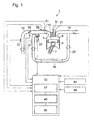
Fig. 1 is a configuration diagram showing the whole configuration of a fuel control unit for a diesel engine according to the first embodiment of the present invention. -
Fig. 2 is a control flow chart of the control unit according to the first embodiment. -
Fig. 3 is a diagram showing the to-be-limited maximum rate of change of the accelerator opening with respect to the threshold values as to the estimation excess air ratio. -
Figs. 4 (a) to (e) are characteristic curves conceptually showing a control flow according to the first embodiment. -
Fig. 5 is a configuration diagram showing the configuration according to the second embodiment of the present invention. -
Fig. 6 is a block diagram that shows the configuration of the control unit according to the second embodiment; -
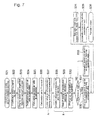
Fig. 7 is a control flow chart for the control unit according to the second embodiment. -
Figs. 8 (a) to (d) are explanatory diagrams explaining a result of the verification test as to the first embodiment. -
Fig. 9 is a configuration diagram showing the configuration according to the third embodiment of the present invention. - Hereafter, the present invention will be described in detail in consultation with the embodiments shown in the figures. However, the dimensions, materials, shape, the relative placement and so on of a component described in these embodiments shall not be construed as limiting the scope of the invention thereto, unless especially specific mention is made.
-
Fig. 1 is a configuration diagram showing the whole configuration of a fuel control unit for a diesel engine according to the first embodiment of the present invention. As depicted inFig. 1 , adiesel engine 1 of a four stroke cycle is provided with apiston 5 that performs a reciprocating motion in acylinder 3 so that the outer periphery of thepiston 5 slides on the inner wall of thecylinder 3, and a crankshaft (not shown) connected to thepiston 5 via a connecting rod 7, through which the reciprocating motion of thepiston 5 is converted into a rotational movement. - In the
engine 1, acombustion chamber 9 is formed over the top surface of thepiston 5 and within the inner surface of thecylinder 3; anintake air passage 13 is connected to thecombustion chamber 9 via an intake air port that is opened and closed by anintake valve 15. Further, anexhaust gas passage 19 is connected to thecombustion chamber 9 via an exhaust gas port that is opened and closed by anexhaust valve 21. - On a part way of the
exhaust gas passage 19, an EGR (Exhaust Gas Re-circulation)passage 23 is branched so as to merge with theintake air passage 13 at the down stream side of an intakeair throttle valve 29. On the EGRpassage 23, an EGRcooler 25 that cools the EGR gas stream in the EGRpassage 23 is provided, and, at the downstream side of theEGR cooler 25, anEGR valve 27 is also provided for regulating the flow rate of the EGR gas. - The opening of the intake
air throttle valve 29 is controlled so as to regulate the flow rate of the intake air inhaled into thecombustion chamber 9. In the case of diesel engines, the opening of the intakeair throttle valve 29 is operated in the direction that closes the intakeair throttle valve 29 when an EGR control is performed, but usually, thethrottle valve 29 is kept in its fully opened condition, and excess air ratio is controlled by the fuel flow rate. - A
fuel injection valve 31 is installed in each cylinder of theengine 1 for injecting fuel pressurized by a fuel injection pump (not shown) into thecombustion chamber 9, and the fuel amount per shot and the injection timing are controlled by a control unit (a fuel admission control means) 33. Thecontrol unit 33 also controls the fuel injection timing so that the fuel is injected at a predetermined point of time; in general, the injection timing can be variably controlled. - An
air flow meter 35 that measures the flow rate of the fresh intake air which is inhaled into thecombustion chamber 9 is fitted on a part way of theintake air passage 13, upstream to theair throttle valve 29; from theair flow meter 35, signals as to the flow-rate of the fresh air are inputted into thecontrol unit 33. Similarly, an EGRgas flow meter 37 that measures the (volume) flow rate of the EGR gas which streams into theintake air passage 13 from theEGR gas passage 23 is fitted on a part way of theEGR gas passage 23, upstream to theEGR valve 27; from the EGRgas flow meter 37, the signals as to the flow-rate of the EGR gas are inputted into thecontrol unit 33. - Further, the engine is provided with an inlet
manifold pressure sensor 39 that detects pressure in an inlet manifold of the engine, and an inletmanifold temperature sensor 41 that detects temperature in the inlet manifold; from thesensors control unit 33. - Further, signals from an
engine speed sensor 43 which detects engine speed, and anaccelerator sensor 45 which detects the stepping amount on the accelerator or the operation amount of accelerator-wheels etc. are inputted to thecontrol unit 33. - Hereinafter, the
control unit 33 is explained. Thecontrol unit 33 according to the first embodiment comprises an estimation excess air ratio λ s computing means 47 that is an arithmetic section to compute an estimation excess air ratio λ in thecylinder 3 from the quantity of the fuel injected by thefuel injection valve 31 into thecylinder 3, the intake air flow rate measured by theair flow meter 35, and the flow rate of the residual oxygen in the EGR gas that flows back to theintake air passage 13. - Further, the
control unit 33 comprises an estimation excess air ratio λ s evaluating means 49 that is an arithmetic section to evaluate whether the estimation excess air ratio λs which is computed by the estimation excess air ratio λ s computing means 47 is smaller than or equal to a threshold value or not, and when the estimation excess air ratio λ s evaluating means 49 evaluates that the estimation excess air ratio λ s is lower than or equal to the threshold value, an accelerator opening controlling means 50 provided in thecontrol unit 33 limits the rate of change of the accelerator opening below a predetermined value. - In connection with a flow chart in
Fig. 2 , a control procedure as to the limitation of the accelerator opening in thecontrol unit 33 is now explained. - After an accelerator opening limitation process is started at Step S1, an accelerator-opening signal is read into the
unit 33 at Step S2. The accelerator-opening signal changes on an hour-by-hour basis, as depicted in the part (a) ofFig. 4 , thereby, the accelerator-opening signal starts from an incipient fixed opening so as to rise with a slope. At the next step S3, threshold values H1 and H2 as to the rates of changes of the accelerator opening are read in order to determine whether the accelerator opening is to be limited or not. If the rate of change of the accelerator opening is greater than or equal to the value H1, then the limitation is held under an ON (limitation ON) condition, and if the rate of change is equal to or lower than H2, the limitation is held under an OFF (limitation OFF) condition. Hereby, an condition H1 > H2 is set so that an unstable behavior as to the accelerator opening or the rate of change thereof can be prevented. The unstable behavior hereby means a hunting phenomenon of the threshold value. - In Step S4, the rate of change of the accelerator opening is calculated based on the accelerator-opening signals that have been read in at Step S2. The rate of change of the accelerator opening corresponds to the slope (the gradient) of the accelerator-opening curve (line) as depicted in the part (a) of
Fig. 4 ; this rate of change is obtained as a curve such as depicted in the part (b) ofFig.4 . However, it is hereby noted that the part (b) is not an example as a differential of the function of the part (a) ; namely, the parts (a) and (b) are only the examples for explaining the terms. - In Step S5, based on the threshold values H1 and H2, the
control unit 33 determines whether the accelerator opening is to be limited or not. More specifically, when the rate of change of the accelerator opening is greater than or equal to the value H1, thecontrol unit 33 determines that the limitation is to be effective, on the other hand, when the rate of change of the accelerator opening becomes lower than or equal to the value H2, then thecontrol unit 33 determines that the limitation is to be ineffective; accordingly, an effective flag or an ineffective flag is set. In the part (c) ofFig.4 , an example of the effective flag in a form of a rectangular step protrusion is shown. - In this way, only when the rate of change of the accelerator opening is greater than or equal to an constant value, the accelerator opening limitation is performed. Therefore, the engine can be free from the across-the-board fuel limitation (the indiscriminate limitation) even during a high load operation where the excess air ratio is low.
- In Step S6, the estimation excess air ratio A s is calculated by the estimation excess air ratio λ s computing means 47 by the use of the following formulae (1) and (2):


whereby, - G a is an intake air mass flow rate;
- G e g r is an EGR gas mass flow rate;
- G e g r a is an air mass flow rate in the EGR gas flow rate;
- G f is a fuel mass quantity injected in a shot;
- L t h is a theoretical air-fuel ratio; and
- ( n ― 1 ) is an index that refers to the former calculation step as to the former data sampling cycle.
- The intake air mass flow rate G a in the formula (1) is calculated by use of a detected signal from the
air flow meter 35; the EGR gas mass flow rate Gegr is calculated through numerical computations based on the EGR gas flow rate detected by the EGRgas flow meter 37 or an measurement as to the pressure drop of the EGR gas through theEGR cooler 25. Hereby, it is noted that the unit as to the pressure drop measurement is not shown in the attached drawings. - The air mass flow rate Gegra in the EGR gas flow rate is estimated by use of the calculation result obtained in the former step as to the former data samplings, using the formula (2). Here, the calculation result means a result of the estimation excess air ratio λ s .
- In Step S7, the estimation excess air ratio λ s evaluating means 49 makes a judgment as to whether or not the calculated estimation excess air ratio λ s is smaller than or equal to a threshold value K as to the estimation excess air ratio. In a case where the estimation excess air ratio λ s is smaller than or equal to the threshold value K, Step 8 is carried out in which the to-be-limited maximum rate of change of the accelerator opening is calculated in response to the estimation excess air ratio λ s. It is hereby noted that the mentioned threshold value K is a variable corresponding to the estimation excess air ratio λ s rather than a constant value; thus, the to-be-limited maximum rate of change of the accelerator opening calculated in step S8 is predetermined as a function of the estimation excess air ratio λ s, or a function of the variable K. In the next step S9, the to-be-limited maximum rate of change of the accelerator opening calculated in the step S8 is limited within a limit value (function) P as shown in
Fig.3 . Further, in Step S10, allowable maximum limit values in response to the ratio λ s or the variables K are memorized so that the allowable maximum limit values are used as control (command) signals. Then, a chain of steps in the accelerator opening limitation process finishes atStep 11. - The limiting process of the maximum rate of change of the accelerator opening in the steps S9 and S10 is carried out by the accelerator opening controlling means 50 of the
control unit 33. - As shown in the part (d) of
Fig. 4 , since the fuel admission level becomes excessive and the engine is prone to emit smoke when the estimation excess air ratio λ s becomes smaller than or equal to a threshold value K, the maximum rate of change of the accelerator opening is decreased to be within a limit value P as shown in the part (e) ofFig. 4 . - In addition, the threshold variable K as to the estimation excess air ratio λ s and the limit value (function) P as to the maximum rate of change of the accelerator opening are predetermined in a form of a table that can be depicted in a figure such as
Fig. 3 . - As depicted in the table function of
Fig. 3 , as the threshold variable K as to the estimation excess air ratio λ s decreases from 1.7 to 1.5 (namely, as the amount of the fuel increases in comparison with the intake air flow rate), the limit value P as an allowable limit as to the maximum rate of change of the accelerator opening is strongly confined to a smaller level of the P; further, when the threshold variable K becomes smaller than or equal to 1.5, the limit value P is set at a constant value, for example, 10% of a maximum allowable value (100%). - As described above, the mentioned threshold value K as to the estimation excess air ratio is a variable corresponding to the estimation excess air ratio λ s an the variable is related to a limit value P as to the rate of change of the accelerator opening; thus, the limit value P is easily adjusted in relation to the threshold value K as to the estimation excess air ratio by adjusting the table. Therefore, the trade-off relation between the smoke emission and the engine speed response can be easily adjusted.
- Since the smoke emission level of the engine can be controlled by only one parameter, namely, the estimation excess air ratio λ s, the control logic becomes more simplified and the control adjustment can be simplified in comparison with the case where a plurality of control parameters are introduced.
- As described above, according to the first embodiment, the estimation excess air ratio λ s computing means 47 calculates the estimation excess air ratio λ s in the
cylinder 3 by use of the following quantities: the quantity of the fuel injected into thecylinder 3, the intake air flow rate fed into thecylinder 3 through theintake air passage 13, and the flow rate of the residual air in the EGR gas returned into theintake air passage 13; thus, the estimation excess air ratio λ s is calculated in consideration of the residual oxygen (the oxygen which is not used for the combustion in the cylinder, and returns back into the intake air passage) that has an impact on the engine smoke emission. - Further, since the accelerator opening (the fuel admission) is controlled based on the estimation excess air ratio λ s, the control can be performed so that the oxygen ratio in the cylinder air or gas can be reflected on the control. Moreover, when the estimation excess air ratio λ s exists in a range smaller than or equal to a constant value, the accelerator opening controlling means 50 limits the rate of change of the accelerator opening so that the rate of change does not exceed a limitation level; thus, even when a hard acceleration (a rapid increase as to the accelerator opening )is performed during the EGR system operation, the smoke emission, the NOx emission, and the engine speed response deterioration due to the oxygen shortage in the
combustion chamber 9 can be restrained. - The dotted line R in the part (a) of
Fig. 4 shows the locus of the accelerator opening after the limitation is performed. When the an effective flag is set (in the ON state), the rate of change of the accelerator opening is limited so that the rate of change does not exceed the limit value P, so the rate of change becomes gentle, and the emitted smoke due to the oxygen shortage in thecombustion chamber 9 can be restrained, the emitted NOx can be reduced, and the engine speed response deterioration can be restrained. - In addition,
Fig. 8 that comprises four parts (a) to (d) explains a result of the verification test as to the effect of the first embodiment. In the part (a), the accelerator opening is altered so as to be limited to the solid line; as depicted by the solid line in the part (b), the fuel injection amount per shot (.i.e. the fuel flow rate) is restrained; however, as depicted by the solid line in the part (c), the estimation excess air ratio λ s changes or increases slightly. As a result, it is confirmed that the smoke emission can be reduced as depicted by the solid line in the part (d). - Next, in consultation with
Figs. 5 to 7 , the second embodiment is now explained. The configuration of the second embodiment is similar to that of the first embodiment; thus, the element in the second embodiment that is equivalent to the element in the first embodiment is given a common numeral, and the explanation as to the common element is omitted. - In the first embodiment, the estimation excess air ratio λ s evaluating means 49 makes a judgment as to whether or not the calculated estimation excess air ratio λ s is reduced, and the accelerator opening controlling means 50 performs a control limitation in relation to the rate of change of the accelerator opening; on the other hand, in the second embodiment the estimation excess air ratio λ s evaluating means 49 is replaced with a target excess air ratio λ m calculating means 52, and the accelerator opening controlling means 50 is replaced with an accelerator opening controlling means 54. In other words, the
control unit 33 of the first embodiment comprises the estimation excess air ratio λ s evaluating means 49 and the accelerator opening controlling means 50, while thecontrol unit 51 of the second embodiment comprises the target excess air ratio λ m calculating means 52 and the accelerator opening controlling means 54 as shown inFigs. 5 and6 . Except the difference of this point, the configuration of the second embodiment is the same as that of the first embodiment. - In
Fig. 6 ,a block diagram of thecontrol unit 51 in the second embodiment is shown; in the target excess air ratio λ m calculating means 52, a map of the target excess air ratio λ m as a function of the engine speed and the target fuel injection amount per shot (i.e. the fuel flow rate) is prescribed. Hereby, in using this map, the engine speed argument and the fuel injection amount argument are set based on the signals detected by theengine speed sensor 43 and theaccelerator sensor 45 respectively. Into the map of the target excess air ratio λ m as a to-be-prescribed function, an optimal results (such as obtained by the experiments in advance) can be incorporated; whereby, the term optimal relates to an optimal condition in regard to the trade-off relation between the NOx emission and the smoke emission, in every possible engine operation condition. - In the accelerator opening controlling means 54 (in
Fig. 5 ), a feedback control is performed so that the estimation excess air ratio λ s that is calculated by the estimation excess air ratio λ s computing means 47 follows-up the target excess air ratio λ m; namely, the ratio λ s tracks the ratio λ m so as to coincide with the ratio λ m. - In consultation with the flowchart of
Fig. 7 , the mechanism of thecontrol unit 51 is now explained. - Firstly, at Step S21, a corrective action as to the accelerator opening starts; in Step S22, a signal as to the accelerator opening is read from the
accelerator sensor 45; in Step S23, an engine speed signal and an accelerator opening signal are read by the target excess air ratio λ m calculating means 52; and in Step S24, a target excess air ratio λ m is calculated by means of the map of the target excess air ratio λ m . - Secondly, in Step S25 , the estimation excess air ratio λ s is calculated by the estimation excess air ratio λ s computing means 47. The calculation is performed by use of the formulae (1) and (2), in the same manner as in the first embodiment. From the estimation excess air ratio λ s, the target excess air ratio λ m is subtracted at an adder-
subtracter 56 inFig. 6 , and the arithmetic operation result is inputted into aPI controller 58 with an anti-windup compensation function; in thePI controller 58, step S26, namely, the PI control computation is performed. After the step S26, Step S27 (procedure A) in which selecting of a minimum value is performed by aminimum value selector 60 shown inFig. 6 by comparing the accelerator opening and the output of the PI control computation is carried out. - In procedure B, namely, in Steps S28 to S30, whether the rate of change of the accelerator opening is greater than or equal to a predetermined threshold value or not is estimated, as is the case in the steps S3 to S5 in the first embodiment. Then, the steps as to corrective process (such as Step S32 and/or S33) follow. In Step S31, if the rate of change of the accelerator opening is greater than or equal to the predetermined threshold value, and the fuel input limitation (the accelerator opening limitation) is regarded as effective, then Step S31 is followed by Step S32 in which the output of the process A (the step S27) is set as an accelerator opening correction value; namely, the output Mi from the
minimum value selector 60 inFig.6 is inputted into a saturation element 62 (aelement 62 with saturation). - On the other hand, in Step S31, if the fuel input limitation (the accelerator opening limitation) is regarded as non-effective, then the Step S31 is followed by Step S33 in which the accelerator opening itself is set as an accelerator opening correction value; namely, the signal itself as to the accelerator opening Ac in
Fig. 6 is inputted into thesaturation element 62 so as to be set as an accelerator opening correction value. - In Step S34 that follows the Step S32 or S33, the signal inputted into the
saturation element 62 through which the input signal is saturated; namely, in theelement 62, the input signal is converted into a signal so that the output signal does not step across the bounds even when the input signal increases or decreases beyond certain limits. Thus, the output signal as an accelerator opening correction value falls within a range of 0% to 100%. Further, in Step S35, the corrected signal as to the accelerator opening is memorized to be used for a control (command) signal. Thus, a chain of steps in the flowchart (Fig. 7 ) finishes at Step S36 . - According to the second embodiment as described above, since the accelerator opening (the fuel admission) is controlled based on the estimation excess air ratio A s, the control with which the oxygen ratio in the cylinder air or gas is accurately reflected on the control can be performed, as is the case in the first embodiment.
- Further, the control unit is provided with the accelerator opening controlling means 54 whereby the accelerator opening is corrected so that the prescribed target excess air ratio λ m is followed up by the estimation excess air ratio λ s which is calculated by the estimation excess air ratio λ s computing means 47; thus, a finer control as to the rate of change of the acceleration opening is performed in the second embodiment than in the first embodiment; in this way, the estimation excess air ratio λ s is accurately controlled so that the air or oxygen content in EGR gas is taken into consideration, whereby the air or oxygen content has a direct influence on the smoke emission level. As a result, the engine smoke emission can be restrained.
- In a transient state during acceleration, the
EGR valve 27 is closed for the purpose of either smoke reduction or response improvement. However, by closing thevalve 27 , the air or gas condition in the inlet manifold varies causing the combustion temperature and the NOx emission level increase rapidly. This difficulty can be solved by the second embodiment, since the estimation excess air ratio λ s can be accurately controlled, theEGR valve 27 can be moderately (not rapidly) closed, and the estimation excess air ratio λ s can be controlled through a quick response of the fuel injection control (the fuel admission control). Therefore, smoke restraint together with NOx reduction can be achieved. - In consultation with
Fig. 9 , the third embodiment is now explained. The configuration of the third embodiment is similar to that of the first embodiment; thus, the element in the third embodiment that is equivalent to the element in the first embodiment is given a common numeral, and the explanation as to the common element is omitted. - In the first embodiment, the estimation excess air ratio λ s evaluating means 49 makes a judgment as to whether the calculated estimation excess air ratio λ s is reduced or not, and the accelerator opening controlling means 50 performs a control limitation in relation to the rate of change of the accelerator opening; on the other hand, in the third embodiment the estimation excess air ratio λ s evaluating means 49 is replaced with an oxygen
concentration evaluating means 73 , and the accelerator opening controlling means 50 is replaced with an accelerator opening controlling means 75. In other words, thecontrol unit 33 of the first embodiment comprises the estimation excess air ratio λ s evaluating means 49 and the accelerator opening controlling means 50, while thecontrol unit 71 of the third embodiment comprises the oxygenconcentration evaluating means 73 and the accelerator opening controlling means 75 as shown inFig. 9 . Except the difference of this point, the configuration of the third embodiment is the same as that of the first embodiment. - As shown
Fig.9 , the engine is provided with anoxygen concentration meter 77 at the inlet manifold that is an air or gas passage at the down stream side of the confluence as to theEGR passage 23 and theintake air passage 13; based on the oxygen concentration measurement, the oxygenconcentration evaluating means 73 makes a judgment as to whether or not a detected oxygen concentration value becomes smaller than or equal to a threshold value as is the case in the first embodiment where the estimation excess air ratio λ s evaluating means 49 makes a judgment as to whether the calculated estimation excess air ratio λ s is reduced or not; in the case where the detected oxygen concentration value becomes smaller than or equal to the threshold value, the accelerator opening controlling means 75 controls the command signals as to the accelerator opening so that the rate of change of the accelerator opening does not exceed a limitation value. - According to the third embodiment, the oxygen concentration in the gas including the intake air and the EGR gas is directly detected by means of the
oxygen concentration meter 77. The fuel injection control (the fuel admission control) in which the detected oxygen concentration is accurately reflected on the control is performed. Accordingly, the fuel injection control can be simplified in comparison with the before-described manner in which the intake gas pressure and temperature are detected so that the estimation excess air ratio A s is calculated through the predetermined formulae. - Moreover, as the reduction of the oxygen concentration, which is the cause of the engine smoke emission, is directly evaluated and then controlled, the fuel injection control which reflects the reduction of the oxygen concentration can surely restrain the smoke emission.
- In the above explanation from the first to third embodiment, the control command signal is directed to the accelerator opening; however, as a matter of course, the command signal may be any other command signal directed to the fuel injection amount (e.g., in some cases of fuel injection valves, the fuel admission index may be the injection time duration).
- According to the present invention, a four-stroke cycle engine with an EGR control unit, in which the engine starting performance such as a quick starting performance is enhanced by being able to avoid a significant descent of speed as to the engine speed during a steady speed operation, can be provided.
- The present disclosure also extends to subject-matter defined by the following series of seven numbered clauses:
- 1. A fuel admission control unit to control a diesel engine, the engine having an EGR system that returns a part of the engine exhaust-gas into an intake air system of the engine, the fuel admission control unit comprising:
- an estimation excess air ratio λs computing means that is an arithmetic section to compute an estimation excess air ratio λs from a quantity of fuel injected by a fuel injection valve into a cylinder, an intake air flow rate measured by an air flow meter, and a flow rate of residual oxygen in the EGR gas that flows back to the intake air system; and
- a fuel admission control means that controls a fuel flow rate under a quick acceleration, based on the estimation excess air ratio λs that is computed by the estimation excess air ratio λs computing means.
- 2. The fuel admission control unit to control the diesel engine according to
clause 1,
wherein the fuel admission control means is provided with an accelerator opening controlling means by which a rate of change of the accelerator opening is limited lower than or equal to a predetermined value when the estimation excess air ratio λs computed by the estimation excess air ratio λs computing means is lower than or equal to a prescribed level. - 3. The fuel admission control unit to control the diesel engine according to
clause 2,
wherein the accelerator opening controlling means uses a predetermined table that prescribes the relation between the estimation excess air ratio λs and the maximum rate of change of the accelerator opening. - 4. The fuel admission control unit to control the diesel engine according to
clause 1,
wherein the fuel admission control means is provided with an accelerator opening controlling means by which the accelerator opening is controlled so that the estimation excess air ratio λs computed by the estimation excess air ratio λs computing means tracks a target excess air ratio λm that is pre-programmed or prescribed. - 5. The fuel admission control unit to control the diesel engine according to
clause 4,
wherein the target excess air ratio λm is preprogrammed or prescribed in regard to an engine speed and a target fuel injection quantity as a function of the engine speed, so as to restrain both smoke emission and NOx emission. - 6. The fuel admission control unit to control the diesel engine according to
clause 1,
wherein the fuel flow rate is controlled under a condition that the rate of change of the accelerator opening exceeds a prescribed level under the quick acceleration, as well as under a condition that the rate of change of the accelerator opening is not less than another prescribed level. - 7. The fuel admission control unit to control the diesel engine according to
clause 1,
wherein the fuel admission control unit comprises,
as a substitute of the estimation excess air ratio λs computing means, an oxygen concentration meter that detects the oxygen concentration of an intake air passage at the down stream side of the position where an EGR passage joins the intake air passage, and
the fuel flow rate under quick acceleration is controlled based on the oxygen concentration detected by the oxygen concentration meter.
Claims (6)
- A fuel admission control unit to control a diesel engine (1), the engine having an EGR system (23) that returns a part of the engine exhaust-gas into an intake air system (13) of the engine, the fuel admission control unit comprising:an estimation excess air ratio λs computing means (47) that is an arithmetic section to compute an estimation excess air ratio λs from a quantity of fuel injected by a fuel injection valve (31) into a cylinder (3), an intake air flow rate measured by an air flow meter (35), and a flow rate of residual oxygen in the EGR gas that flows back to the intake air system (13); anda fuel admission control means (51) that controls a fuel flow rate under a quick acceleration, based on the estimation excess air ratio λs that is computed by the estimation excess air ratio λs computing means (47),wherein the fuel admission control means (51) is provided with an accelerator opening controlling means (54) by which the accelerator opening is controlled so that the estimation excess air ratio λs computed by the estimation excess air ratio λs computing means (47) tracks a target excess air ratio λm that is pre-programmed or prescribed.
- The fuel admission control unit to control the diesel engine according to claim 1,
wherein the target excess air ratio λm is preprogrammed or prescribed in a map in regard to an engine speed and a target fuel injection quantity as a function of the engine speed, so as to restrain both smoke emission and NOx emission. - The fuel admission control unit to control the diesel engine according to claim 1 or 2 wherein the fuel admission control means (51) further comprises:a PI controller (58) arranged to compute a deviation between said target excess air ratio Xm and said estimation excess air ratio Xs; anda minimum value selector (60) arranged to select between a fuel command signal after a PI computation is performed or an actual fuel command signal, whichever has the smaller value.
- A fuel admission control unit to control a diesel engine (1), the engine having an EGR system (23) that returns a part of the engine exhaust-gas into an intake air system (13) of the engine, the fuel admission control unit comprising:an oxygen concentration meter (77) that detects the oxygen concentration of an intake air passage (13) at the down stream side of the position where an EGR passage (23) joins the intake air passage (13); anda fuel admission control means (71) that controls a fuel flow rate under a quick acceleration, based on the oxygen concentration detected by the oxygen concentration meter (77).
- The fuel admission control unit to control the diesel engine according to claim 4, wherein the fuel admission control means (71) comprises an oxygen concentration evaluating means (73) and an accelerator opening control means (75).
- The fuel admission control unit to control the diesel engine according to any preceding claim,
wherein the fuel flow rate is controlled under a condition that the rate of change of the accelerator opening exceeds a prescribed level under the quick acceleration, as well as under a condition that the rate of change of the accelerator opening is not less than another prescribed level.
Applications Claiming Priority (2)
| Application Number | Priority Date | Filing Date | Title |
|---|---|---|---|
| JP2008122732A JP4981743B2 (en) | 2008-05-08 | 2008-05-08 | Diesel engine fuel control system |
| EP20090742686 EP2196656B1 (en) | 2008-05-08 | 2009-04-21 | Fuel control system for diesel engine |
Related Parent Applications (3)
| Application Number | Title | Priority Date | Filing Date |
|---|---|---|---|
| EP09742686.0 Division | 2009-04-21 | ||
| EP20090742686 Division EP2196656B1 (en) | 2008-05-08 | 2009-04-21 | Fuel control system for diesel engine |
| EP20090742686 Division-Into EP2196656B1 (en) | 2008-05-08 | 2009-04-21 | Fuel control system for diesel engine |
Publications (3)
| Publication Number | Publication Date |
|---|---|
| EP2412957A2 true EP2412957A2 (en) | 2012-02-01 |
| EP2412957A3 EP2412957A3 (en) | 2014-12-17 |
| EP2412957B1 EP2412957B1 (en) | 2018-04-11 |
Family
ID=41264617
Family Applications (2)
| Application Number | Title | Priority Date | Filing Date |
|---|---|---|---|
| EP11186662.0A Not-in-force EP2412957B1 (en) | 2008-05-08 | 2009-04-21 | A fuel admission control unit to control a diesel engine |
| EP20090742686 Not-in-force EP2196656B1 (en) | 2008-05-08 | 2009-04-21 | Fuel control system for diesel engine |
Family Applications After (1)
| Application Number | Title | Priority Date | Filing Date |
|---|---|---|---|
| EP20090742686 Not-in-force EP2196656B1 (en) | 2008-05-08 | 2009-04-21 | Fuel control system for diesel engine |
Country Status (8)
| Country | Link |
|---|---|
| US (1) | US9008951B2 (en) |
| EP (2) | EP2412957B1 (en) |
| JP (1) | JP4981743B2 (en) |
| KR (1) | KR101185756B1 (en) |
| CN (1) | CN101965447B (en) |
| BR (1) | BRPI0904954B1 (en) |
| RU (1) | RU2432481C1 (en) |
| WO (1) | WO2009136562A1 (en) |
Families Citing this family (22)
| Publication number | Priority date | Publication date | Assignee | Title |
|---|---|---|---|---|
| JP4981743B2 (en) * | 2008-05-08 | 2012-07-25 | 三菱重工業株式会社 | Diesel engine fuel control system |
| BR112012026928B1 (en) * | 2010-04-22 | 2020-06-09 | Int Eng Ip Co Llc | compression ignition engine and method of distributing smoke and nox in exhaust gases |
| JP5341041B2 (en) * | 2010-09-06 | 2013-11-13 | 株式会社小松製作所 | Hydraulically driven vehicle and method and apparatus for controlling the same |
| JP5704250B2 (en) * | 2011-10-06 | 2015-04-22 | トヨタ自動車株式会社 | Control device for internal combustion engine |
| SE538206C2 (en) * | 2012-07-05 | 2016-04-05 | Scania Cv Ab | Procedure and system for driving a vehicle, where the air / fuel ratio is controlled |
| US10012153B2 (en) | 2012-08-15 | 2018-07-03 | General Electric Company | System and method for engine control |
| JP6259246B2 (en) | 2013-10-09 | 2018-01-10 | 三菱重工業株式会社 | Control device for internal combustion engine |
| BR112016013746A2 (en) * | 2013-12-20 | 2017-08-08 | Toyota Motor Co Ltd | EXHAUST GAS CONTROL APPLIANCE FOR INTERNAL COMBUSTION ENGINE |
| US9422878B2 (en) * | 2014-04-14 | 2016-08-23 | Ford Global Technologies, Llc | EGR operation method and system for increased drivability |
| US9284920B2 (en) * | 2014-06-19 | 2016-03-15 | Ford Global Technologies, Llc | Systems and methods for stopping and starting an engine with dedicated EGR |
| US10221798B2 (en) | 2015-12-01 | 2019-03-05 | Ge Global Sourcing Llc | Method and systems for airflow control |
| JP6681251B2 (en) * | 2016-04-05 | 2020-04-15 | ヤンマー株式会社 | Engine control method |
| CN105756792A (en) * | 2016-05-05 | 2016-07-13 | 孟书芳 | Novel diesel engine capable of intelligently controlling combustion |
| WO2019017928A1 (en) * | 2017-07-19 | 2019-01-24 | Cummins Inc. | Techniques for transient estimation and compensation of control parameters for dedicated egr engines |
| KR102532330B1 (en) * | 2017-12-12 | 2023-05-16 | 현대자동차주식회사 | Hydrogen concentration estimating method and system for fuel cell |
| FR3078746A1 (en) * | 2018-03-08 | 2019-09-13 | Psa Automobiles Sa | METHOD FOR CONTROLLING A THERMAL ENGINE FOLLOWING APPLICATIONS FOR LIMITING THE EMISSIONS OF NITROGEN OXIDES AND / OR PARTICLES |
| KR102637599B1 (en) * | 2018-10-08 | 2024-02-19 | 주식회사 에이치엘클레무브 | Apparatus and Method for Controlling Lane Changing using Vehicle-to-Vehicle Communication and Tendency Information Calculation Apparatus therefor |
| JP7667096B2 (en) * | 2019-07-03 | 2025-04-22 | ドナルドソン カンパニー,インコーポレイティド | Fluid aeration detection system and method |
| EP4161676B1 (en) * | 2020-06-09 | 2024-10-02 | Takeda Pharmaceutical Company Limited | Filter press adapter |
| EP4226125A1 (en) | 2020-10-07 | 2023-08-16 | Donaldson Company, Inc. | On-vehicle water in fuel sensing system and related signal processing |
| CN113431690B (en) * | 2021-07-20 | 2023-03-21 | 潍柴动力股份有限公司 | Control method and device of engine management system |
| US12352697B2 (en) | 2022-03-16 | 2025-07-08 | Donaldson Company, Inc. | Air bubble sensing systems and related signal processing |
Citations (2)
| Publication number | Priority date | Publication date | Assignee | Title |
|---|---|---|---|---|
| JPH09151761A (en) | 1995-12-01 | 1997-06-10 | Toyota Motor Corp | Fuel control device for internal combustion engine |
| JPH1136962A (en) | 1997-07-18 | 1999-02-09 | Toyota Motor Corp | Fuel injection control system for diesel engine |
Family Cites Families (27)
| Publication number | Priority date | Publication date | Assignee | Title |
|---|---|---|---|---|
| US4185604A (en) * | 1977-04-12 | 1980-01-29 | Nissan Motor Company, Limited | Feedback control system for gas flow in internal combustion engine for purpose of exhaust gas purification |
| JPS6090950A (en) | 1983-10-24 | 1985-05-22 | Nissan Motor Co Ltd | Fuel controlling apparatus for diesel engine |
| IT1234958B (en) | 1989-06-20 | 1992-06-02 | Weber Srl | ELECTRONIC FUEL INJECTION SYSTEM FOR COMBUSTION ENGINES, WITH SELF ADAPTIVE STRATEGIES TO CORRECT THE DEVIATIONS FROM THE OPTIMAL RATIO FOR THE QUANTITIES OF AIR AND PETROL SUPPLIED TO THE ENGINE |
| DE69636687T2 (en) * | 1995-06-02 | 2007-10-18 | Mitsubishi Jidosha Kogyo K.K. | DEVICE FOR DETECTING AND CONTROLLING THE AIR SURFACE FACTOR OF AN INTERNAL COMBUSTION ENGINE |
| US5553575A (en) | 1995-06-16 | 1996-09-10 | Servojet Products International | Lambda control by skip fire of unthrottled gas fueled engines |
| US5918582A (en) * | 1995-07-13 | 1999-07-06 | Nissan Motor | Integrated internal combustion engine control system with high-precision emission controls |
| JPH09126060A (en) * | 1995-11-08 | 1997-05-13 | Isuzu Motors Ltd | Exhaust gas recirculation control method and device thereof |
| JPH09195825A (en) | 1996-01-18 | 1997-07-29 | Toyota Motor Corp | Diesel engine controller |
| GB2313927B (en) * | 1996-06-03 | 1999-06-23 | Nissan Motor | EGR control apparatus for internal combustion engine |
| US5938975A (en) | 1996-12-23 | 1999-08-17 | Ennis; Bernard | Method and apparatus for total energy fuel conversion systems |
| JP3813332B2 (en) * | 1997-10-27 | 2006-08-23 | 三菱電機株式会社 | In-cylinder injection fuel control system for internal combustion engine |
| JP3341665B2 (en) | 1997-12-22 | 2002-11-05 | トヨタ自動車株式会社 | Injection control system for diesel engine during transient |
| DE19900740A1 (en) * | 1999-01-12 | 2000-07-13 | Bosch Gmbh Robert | Method and device for operating an internal combustion engine |
| US6095127A (en) * | 1999-01-26 | 2000-08-01 | Ford Global Technologies, Inc. | Fuel limiting method in diesel engines having exhaust gas recirculation |
| DE19917208A1 (en) * | 1999-04-16 | 2000-10-19 | Bosch Gmbh Robert | Testing of a vehicle computer by supplying test data to one or more program modules so that the results can be checked against expected results and an error condition indicated if necessary |
| JP4055312B2 (en) | 1999-12-03 | 2008-03-05 | いすゞ自動車株式会社 | Fuel injection control device for supercharged diesel engine |
| JP4284906B2 (en) | 2001-02-28 | 2009-06-24 | 株式会社デンソー | Control device for internal combustion engine |
| JP4285141B2 (en) * | 2003-07-31 | 2009-06-24 | 日産自動車株式会社 | Fuel injection control device for diesel engine |
| JP2005264785A (en) * | 2004-03-17 | 2005-09-29 | Nissan Motor Co Ltd | Diesel engine exhaust aftertreatment system |
| JP4126560B2 (en) * | 2004-09-15 | 2008-07-30 | トヨタ自動車株式会社 | Control device for internal combustion engine |
| JP4186899B2 (en) | 2004-09-30 | 2008-11-26 | 株式会社日立製作所 | Exhaust gas recirculation control device |
| RU45468U1 (en) * | 2005-01-24 | 2005-05-10 | Корабельников Сергей Кимович | SYSTEM OF CLEANING AND RECIRCULATION OF EXHAUST GASES OF THE DIESEL ENGINE |
| JP4049158B2 (en) | 2005-03-09 | 2008-02-20 | トヨタ自動車株式会社 | Fuel injection control device for internal combustion engine |
| JP2006316708A (en) * | 2005-05-13 | 2006-11-24 | Hitachi Ltd | Engine control device |
| JP2008215112A (en) * | 2007-02-28 | 2008-09-18 | Mitsubishi Heavy Ind Ltd | Diesel engine system and its control method |
| JP4981743B2 (en) * | 2008-05-08 | 2012-07-25 | 三菱重工業株式会社 | Diesel engine fuel control system |
| JP4859875B2 (en) * | 2008-05-12 | 2012-01-25 | 三菱重工業株式会社 | Diesel engine exhaust gas recirculation control system |
-
2008
- 2008-05-08 JP JP2008122732A patent/JP4981743B2/en not_active Expired - Fee Related
-
2009
- 2009-04-21 US US12/679,403 patent/US9008951B2/en not_active Expired - Fee Related
- 2009-04-21 CN CN200980100675.0A patent/CN101965447B/en not_active Expired - Fee Related
- 2009-04-21 KR KR1020107007772A patent/KR101185756B1/en not_active Expired - Fee Related
- 2009-04-21 RU RU2010114261A patent/RU2432481C1/en active
- 2009-04-21 EP EP11186662.0A patent/EP2412957B1/en not_active Not-in-force
- 2009-04-21 WO PCT/JP2009/058235 patent/WO2009136562A1/en not_active Ceased
- 2009-04-21 EP EP20090742686 patent/EP2196656B1/en not_active Not-in-force
- 2009-04-21 BR BRPI0904954-1A patent/BRPI0904954B1/en not_active IP Right Cessation
Patent Citations (2)
| Publication number | Priority date | Publication date | Assignee | Title |
|---|---|---|---|---|
| JPH09151761A (en) | 1995-12-01 | 1997-06-10 | Toyota Motor Corp | Fuel control device for internal combustion engine |
| JPH1136962A (en) | 1997-07-18 | 1999-02-09 | Toyota Motor Corp | Fuel injection control system for diesel engine |
Also Published As
| Publication number | Publication date |
|---|---|
| CN101965447A (en) | 2011-02-02 |
| BRPI0904954A2 (en) | 2015-06-30 |
| US9008951B2 (en) | 2015-04-14 |
| EP2196656A1 (en) | 2010-06-16 |
| US20100211295A1 (en) | 2010-08-19 |
| EP2412957B1 (en) | 2018-04-11 |
| JP4981743B2 (en) | 2012-07-25 |
| EP2196656A4 (en) | 2011-03-09 |
| EP2196656B1 (en) | 2012-08-29 |
| JP2009270518A (en) | 2009-11-19 |
| EP2412957A3 (en) | 2014-12-17 |
| RU2432481C1 (en) | 2011-10-27 |
| KR101185756B1 (en) | 2012-09-25 |
| KR20100068428A (en) | 2010-06-23 |
| CN101965447B (en) | 2014-12-31 |
| BRPI0904954B1 (en) | 2019-05-21 |
| WO2009136562A1 (en) | 2009-11-12 |
Similar Documents
| Publication | Publication Date | Title |
|---|---|---|
| EP2412957B1 (en) | A fuel admission control unit to control a diesel engine | |
| EP1864012B1 (en) | Coordinated multivariable control of fuel and air in engines | |
| US8479716B2 (en) | Exhaust gas re-circulation control unit for a diesel engine | |
| US10190516B2 (en) | Method of feedforward turbocharger control for boosted engines with multi-route EGR | |
| US7328577B2 (en) | Multivariable control for an engine | |
| US7165399B2 (en) | Method and system for using a measure of fueling rate in the air side control of an engine | |
| JP4320684B2 (en) | Exhaust gas recirculation device for internal combustion engine | |
| US7591135B2 (en) | Method and system for using a measure of fueling rate in the air side control of an engine | |
| USRE44452E1 (en) | Pedal position and/or pedal change rate for use in control of an engine | |
| US8640679B2 (en) | Method of model-based multivariable control of EGR and boost for internal combustion engines | |
| CN101313138A (en) | Control system for diesel engine | |
| US20130192568A1 (en) | Engine controlling emissions during transient operations | |
| US20170030260A1 (en) | Control device of an engine | |
| JP6421702B2 (en) | Combustion system controller | |
| US10907561B2 (en) | Estimation device and control device for combustion system | |
| JP4228953B2 (en) | Control device for internal combustion engine | |
| JP7177385B2 (en) | engine controller |
Legal Events
| Date | Code | Title | Description |
|---|---|---|---|
| AC | Divisional application: reference to earlier application |
Ref document number: 2196656 Country of ref document: EP Kind code of ref document: P |
|
| AK | Designated contracting states |
Kind code of ref document: A2 Designated state(s): AT BE BG CH CY CZ DE DK EE ES FI FR GB GR HR HU IE IS IT LI LT LU LV MC MK MT NL NO PL PT RO SE SI SK TR |
|
| PUAI | Public reference made under article 153(3) epc to a published international application that has entered the european phase |
Free format text: ORIGINAL CODE: 0009012 |
|
| RIC1 | Information provided on ipc code assigned before grant |
Ipc: F02D 45/00 20060101ALI20140708BHEP Ipc: F02D 41/10 20060101AFI20140708BHEP |
|
| PUAL | Search report despatched |
Free format text: ORIGINAL CODE: 0009013 |
|
| AK | Designated contracting states |
Kind code of ref document: A3 Designated state(s): AT BE BG CH CY CZ DE DK EE ES FI FR GB GR HR HU IE IS IT LI LT LU LV MC MK MT NL NO PL PT RO SE SI SK TR |
|
| RIC1 | Information provided on ipc code assigned before grant |
Ipc: F02D 41/10 20060101AFI20141112BHEP Ipc: F02D 45/00 20060101ALI20141112BHEP |
|
| 17P | Request for examination filed |
Effective date: 20150609 |
|
| GRAP | Despatch of communication of intention to grant a patent |
Free format text: ORIGINAL CODE: EPIDOSNIGR1 |
|
| INTG | Intention to grant announced |
Effective date: 20171215 |
|
| GRAS | Grant fee paid |
Free format text: ORIGINAL CODE: EPIDOSNIGR3 |
|
| GRAA | (expected) grant |
Free format text: ORIGINAL CODE: 0009210 |
|
| AC | Divisional application: reference to earlier application |
Ref document number: 2196656 Country of ref document: EP Kind code of ref document: P |
|
| AK | Designated contracting states |
Kind code of ref document: B1 Designated state(s): AT BE BG CH CY CZ DE DK EE ES FI FR GB GR HR HU IE IS IT LI LT LU LV MC MK MT NL NO PL PT RO SE SI SK TR |
|
| REG | Reference to a national code |
Ref country code: GB Ref legal event code: FG4D |
|
| REG | Reference to a national code |
Ref country code: CH Ref legal event code: EP |
|
| REG | Reference to a national code |
Ref country code: AT Ref legal event code: REF Ref document number: 988281 Country of ref document: AT Kind code of ref document: T Effective date: 20180415 |
|
| REG | Reference to a national code |
Ref country code: IE Ref legal event code: FG4D |
|
| REG | Reference to a national code |
Ref country code: DE Ref legal event code: R096 Ref document number: 602009051801 Country of ref document: DE |
|
| REG | Reference to a national code |
Ref country code: NL Ref legal event code: MP Effective date: 20180411 |
|
| REG | Reference to a national code |
Ref country code: LT Ref legal event code: MG4D |
|
| PG25 | Lapsed in a contracting state [announced via postgrant information from national office to epo] |
Ref country code: NL Free format text: LAPSE BECAUSE OF FAILURE TO SUBMIT A TRANSLATION OF THE DESCRIPTION OR TO PAY THE FEE WITHIN THE PRESCRIBED TIME-LIMIT Effective date: 20180411 |
|
| PG25 | Lapsed in a contracting state [announced via postgrant information from national office to epo] |
Ref country code: ES Free format text: LAPSE BECAUSE OF FAILURE TO SUBMIT A TRANSLATION OF THE DESCRIPTION OR TO PAY THE FEE WITHIN THE PRESCRIBED TIME-LIMIT Effective date: 20180411 Ref country code: PL Free format text: LAPSE BECAUSE OF FAILURE TO SUBMIT A TRANSLATION OF THE DESCRIPTION OR TO PAY THE FEE WITHIN THE PRESCRIBED TIME-LIMIT Effective date: 20180411 Ref country code: SE Free format text: LAPSE BECAUSE OF FAILURE TO SUBMIT A TRANSLATION OF THE DESCRIPTION OR TO PAY THE FEE WITHIN THE PRESCRIBED TIME-LIMIT Effective date: 20180411 Ref country code: NO Free format text: LAPSE BECAUSE OF FAILURE TO SUBMIT A TRANSLATION OF THE DESCRIPTION OR TO PAY THE FEE WITHIN THE PRESCRIBED TIME-LIMIT Effective date: 20180711 Ref country code: FI Free format text: LAPSE BECAUSE OF FAILURE TO SUBMIT A TRANSLATION OF THE DESCRIPTION OR TO PAY THE FEE WITHIN THE PRESCRIBED TIME-LIMIT Effective date: 20180411 Ref country code: LT Free format text: LAPSE BECAUSE OF FAILURE TO SUBMIT A TRANSLATION OF THE DESCRIPTION OR TO PAY THE FEE WITHIN THE PRESCRIBED TIME-LIMIT Effective date: 20180411 Ref country code: BG Free format text: LAPSE BECAUSE OF FAILURE TO SUBMIT A TRANSLATION OF THE DESCRIPTION OR TO PAY THE FEE WITHIN THE PRESCRIBED TIME-LIMIT Effective date: 20180711 |
|
| PG25 | Lapsed in a contracting state [announced via postgrant information from national office to epo] |
Ref country code: GR Free format text: LAPSE BECAUSE OF FAILURE TO SUBMIT A TRANSLATION OF THE DESCRIPTION OR TO PAY THE FEE WITHIN THE PRESCRIBED TIME-LIMIT Effective date: 20180712 Ref country code: HR Free format text: LAPSE BECAUSE OF FAILURE TO SUBMIT A TRANSLATION OF THE DESCRIPTION OR TO PAY THE FEE WITHIN THE PRESCRIBED TIME-LIMIT Effective date: 20180411 Ref country code: LV Free format text: LAPSE BECAUSE OF FAILURE TO SUBMIT A TRANSLATION OF THE DESCRIPTION OR TO PAY THE FEE WITHIN THE PRESCRIBED TIME-LIMIT Effective date: 20180411 |
|
| REG | Reference to a national code |
Ref country code: CH Ref legal event code: PL |
|
| REG | Reference to a national code |
Ref country code: AT Ref legal event code: MK05 Ref document number: 988281 Country of ref document: AT Kind code of ref document: T Effective date: 20180411 |
|
| REG | Reference to a national code |
Ref country code: BE Ref legal event code: MM Effective date: 20180430 |
|
| PG25 | Lapsed in a contracting state [announced via postgrant information from national office to epo] |
Ref country code: PT Free format text: LAPSE BECAUSE OF FAILURE TO SUBMIT A TRANSLATION OF THE DESCRIPTION OR TO PAY THE FEE WITHIN THE PRESCRIBED TIME-LIMIT Effective date: 20180813 |
|
| REG | Reference to a national code |
Ref country code: DE Ref legal event code: R097 Ref document number: 602009051801 Country of ref document: DE |
|
| REG | Reference to a national code |
Ref country code: IE Ref legal event code: MM4A |
|
| PG25 | Lapsed in a contracting state [announced via postgrant information from national office to epo] |
Ref country code: CZ Free format text: LAPSE BECAUSE OF FAILURE TO SUBMIT A TRANSLATION OF THE DESCRIPTION OR TO PAY THE FEE WITHIN THE PRESCRIBED TIME-LIMIT Effective date: 20180411 Ref country code: RO Free format text: LAPSE BECAUSE OF FAILURE TO SUBMIT A TRANSLATION OF THE DESCRIPTION OR TO PAY THE FEE WITHIN THE PRESCRIBED TIME-LIMIT Effective date: 20180411 Ref country code: SK Free format text: LAPSE BECAUSE OF FAILURE TO SUBMIT A TRANSLATION OF THE DESCRIPTION OR TO PAY THE FEE WITHIN THE PRESCRIBED TIME-LIMIT Effective date: 20180411 Ref country code: EE Free format text: LAPSE BECAUSE OF FAILURE TO SUBMIT A TRANSLATION OF THE DESCRIPTION OR TO PAY THE FEE WITHIN THE PRESCRIBED TIME-LIMIT Effective date: 20180411 Ref country code: DK Free format text: LAPSE BECAUSE OF FAILURE TO SUBMIT A TRANSLATION OF THE DESCRIPTION OR TO PAY THE FEE WITHIN THE PRESCRIBED TIME-LIMIT Effective date: 20180411 Ref country code: AT Free format text: LAPSE BECAUSE OF FAILURE TO SUBMIT A TRANSLATION OF THE DESCRIPTION OR TO PAY THE FEE WITHIN THE PRESCRIBED TIME-LIMIT Effective date: 20180411 Ref country code: MC Free format text: LAPSE BECAUSE OF FAILURE TO SUBMIT A TRANSLATION OF THE DESCRIPTION OR TO PAY THE FEE WITHIN THE PRESCRIBED TIME-LIMIT Effective date: 20180411 Ref country code: LU Free format text: LAPSE BECAUSE OF NON-PAYMENT OF DUE FEES Effective date: 20180421 |
|
| PLBE | No opposition filed within time limit |
Free format text: ORIGINAL CODE: 0009261 |
|
| STAA | Information on the status of an ep patent application or granted ep patent |
Free format text: STATUS: NO OPPOSITION FILED WITHIN TIME LIMIT |
|
| PG25 | Lapsed in a contracting state [announced via postgrant information from national office to epo] |
Ref country code: LI Free format text: LAPSE BECAUSE OF NON-PAYMENT OF DUE FEES Effective date: 20180430 Ref country code: BE Free format text: LAPSE BECAUSE OF NON-PAYMENT OF DUE FEES Effective date: 20180430 Ref country code: CH Free format text: LAPSE BECAUSE OF NON-PAYMENT OF DUE FEES Effective date: 20180430 |
|
| 26N | No opposition filed |
Effective date: 20190114 |
|
| PG25 | Lapsed in a contracting state [announced via postgrant information from national office to epo] |
Ref country code: FR Free format text: LAPSE BECAUSE OF NON-PAYMENT OF DUE FEES Effective date: 20180430 Ref country code: IE Free format text: LAPSE BECAUSE OF NON-PAYMENT OF DUE FEES Effective date: 20180421 |
|
| PG25 | Lapsed in a contracting state [announced via postgrant information from national office to epo] |
Ref country code: SI Free format text: LAPSE BECAUSE OF FAILURE TO SUBMIT A TRANSLATION OF THE DESCRIPTION OR TO PAY THE FEE WITHIN THE PRESCRIBED TIME-LIMIT Effective date: 20180411 |
|
| PG25 | Lapsed in a contracting state [announced via postgrant information from national office to epo] |
Ref country code: MT Free format text: LAPSE BECAUSE OF NON-PAYMENT OF DUE FEES Effective date: 20180421 |
|
| PG25 | Lapsed in a contracting state [announced via postgrant information from national office to epo] |
Ref country code: TR Free format text: LAPSE BECAUSE OF FAILURE TO SUBMIT A TRANSLATION OF THE DESCRIPTION OR TO PAY THE FEE WITHIN THE PRESCRIBED TIME-LIMIT Effective date: 20180411 |
|
| PG25 | Lapsed in a contracting state [announced via postgrant information from national office to epo] |
Ref country code: HU Free format text: LAPSE BECAUSE OF FAILURE TO SUBMIT A TRANSLATION OF THE DESCRIPTION OR TO PAY THE FEE WITHIN THE PRESCRIBED TIME-LIMIT; INVALID AB INITIO Effective date: 20090421 |
|
| PG25 | Lapsed in a contracting state [announced via postgrant information from national office to epo] |
Ref country code: CY Free format text: LAPSE BECAUSE OF FAILURE TO SUBMIT A TRANSLATION OF THE DESCRIPTION OR TO PAY THE FEE WITHIN THE PRESCRIBED TIME-LIMIT Effective date: 20180411 Ref country code: MK Free format text: LAPSE BECAUSE OF NON-PAYMENT OF DUE FEES Effective date: 20180411 |
|
| PG25 | Lapsed in a contracting state [announced via postgrant information from national office to epo] |
Ref country code: IS Free format text: LAPSE BECAUSE OF FAILURE TO SUBMIT A TRANSLATION OF THE DESCRIPTION OR TO PAY THE FEE WITHIN THE PRESCRIBED TIME-LIMIT Effective date: 20180811 |
|
| PGFP | Annual fee paid to national office [announced via postgrant information from national office to epo] |
Ref country code: IT Payment date: 20210310 Year of fee payment: 13 |
|
| PGFP | Annual fee paid to national office [announced via postgrant information from national office to epo] |
Ref country code: GB Payment date: 20210324 Year of fee payment: 13 |
|
| PGFP | Annual fee paid to national office [announced via postgrant information from national office to epo] |
Ref country code: DE Payment date: 20210323 Year of fee payment: 13 |
|
| REG | Reference to a national code |
Ref country code: DE Ref legal event code: R119 Ref document number: 602009051801 Country of ref document: DE |
|
| GBPC | Gb: european patent ceased through non-payment of renewal fee |
Effective date: 20220421 |
|
| PG25 | Lapsed in a contracting state [announced via postgrant information from national office to epo] |
Ref country code: GB Free format text: LAPSE BECAUSE OF NON-PAYMENT OF DUE FEES Effective date: 20220421 Ref country code: DE Free format text: LAPSE BECAUSE OF NON-PAYMENT OF DUE FEES Effective date: 20221103 |
|
| PG25 | Lapsed in a contracting state [announced via postgrant information from national office to epo] |
Ref country code: IT Free format text: LAPSE BECAUSE OF NON-PAYMENT OF DUE FEES Effective date: 20220421 |