EP2412904A2 - Roof or facade structure tilt member opening stop - Google Patents
Roof or facade structure tilt member opening stop Download PDFInfo
- Publication number
- EP2412904A2 EP2412904A2 EP20110175382 EP11175382A EP2412904A2 EP 2412904 A2 EP2412904 A2 EP 2412904A2 EP 20110175382 EP20110175382 EP 20110175382 EP 11175382 A EP11175382 A EP 11175382A EP 2412904 A2 EP2412904 A2 EP 2412904A2
- Authority
- EP
- European Patent Office
- Prior art keywords
- connecting member
- axis
- opening stop
- mandrel
- pivot
- Prior art date
- Legal status (The legal status is an assumption and is not a legal conclusion. Google has not performed a legal analysis and makes no representation as to the accuracy of the status listed.)
- Withdrawn
Links
- 230000013011 mating Effects 0.000 claims abstract description 5
- 230000005484 gravity Effects 0.000 description 5
- 230000000977 initiatory effect Effects 0.000 description 3
- 230000000694 effects Effects 0.000 description 2
- 238000006243 chemical reaction Methods 0.000 description 1
- 230000002844 continuous effect Effects 0.000 description 1
- 230000008878 coupling Effects 0.000 description 1
- 238000010168 coupling process Methods 0.000 description 1
- 238000005859 coupling reaction Methods 0.000 description 1
- 230000001419 dependent effect Effects 0.000 description 1
Images

Classifications
-
- E—FIXED CONSTRUCTIONS
- E05—LOCKS; KEYS; WINDOW OR DOOR FITTINGS; SAFES
- E05D—HINGES OR SUSPENSION DEVICES FOR DOORS, WINDOWS OR WINGS
- E05D15/00—Suspension arrangements for wings
- E05D15/40—Suspension arrangements for wings supported on arms movable in vertical planes
-
- E—FIXED CONSTRUCTIONS
- E05—LOCKS; KEYS; WINDOW OR DOOR FITTINGS; SAFES
- E05C—BOLTS OR FASTENING DEVICES FOR WINGS, SPECIALLY FOR DOORS OR WINDOWS
- E05C17/00—Devices for holding wings open; Devices for limiting opening of wings or for holding wings open by a movable member extending between frame and wing; Braking devices, stops or buffers, combined therewith
- E05C17/02—Devices for holding wings open; Devices for limiting opening of wings or for holding wings open by a movable member extending between frame and wing; Braking devices, stops or buffers, combined therewith by mechanical means
- E05C17/04—Devices for holding wings open; Devices for limiting opening of wings or for holding wings open by a movable member extending between frame and wing; Braking devices, stops or buffers, combined therewith by mechanical means with a movable bar or equivalent member extending between frame and wing
- E05C17/32—Devices for holding wings open; Devices for limiting opening of wings or for holding wings open by a movable member extending between frame and wing; Braking devices, stops or buffers, combined therewith by mechanical means with a movable bar or equivalent member extending between frame and wing consisting of two or more pivoted rods
-
- E—FIXED CONSTRUCTIONS
- E05—LOCKS; KEYS; WINDOW OR DOOR FITTINGS; SAFES
- E05D—HINGES OR SUSPENSION DEVICES FOR DOORS, WINDOWS OR WINGS
- E05D15/00—Suspension arrangements for wings
- E05D15/40—Suspension arrangements for wings supported on arms movable in vertical planes
- E05D15/406—Suspension arrangements for wings supported on arms movable in vertical planes with pivoted arms and sliding guides
-
- E—FIXED CONSTRUCTIONS
- E05—LOCKS; KEYS; WINDOW OR DOOR FITTINGS; SAFES
- E05Y—INDEXING SCHEME ASSOCIATED WITH SUBCLASSES E05D AND E05F, RELATING TO CONSTRUCTION ELEMENTS, ELECTRIC CONTROL, POWER SUPPLY, POWER SIGNAL OR TRANSMISSION, USER INTERFACES, MOUNTING OR COUPLING, DETAILS, ACCESSORIES, AUXILIARY OPERATIONS NOT OTHERWISE PROVIDED FOR, APPLICATION THEREOF
- E05Y2201/00—Constructional elements; Accessories therefor
- E05Y2201/20—Brakes; Disengaging means; Holders; Stops; Valves; Accessories therefor
- E05Y2201/224—Stops
-
- E—FIXED CONSTRUCTIONS
- E05—LOCKS; KEYS; WINDOW OR DOOR FITTINGS; SAFES
- E05Y—INDEXING SCHEME ASSOCIATED WITH SUBCLASSES E05D AND E05F, RELATING TO CONSTRUCTION ELEMENTS, ELECTRIC CONTROL, POWER SUPPLY, POWER SIGNAL OR TRANSMISSION, USER INTERFACES, MOUNTING OR COUPLING, DETAILS, ACCESSORIES, AUXILIARY OPERATIONS NOT OTHERWISE PROVIDED FOR, APPLICATION THEREOF
- E05Y2800/00—Details, accessories and auxiliary operations not otherwise provided for
- E05Y2800/74—Specific positions
- E05Y2800/748—Specific positions end
-
- E—FIXED CONSTRUCTIONS
- E05—LOCKS; KEYS; WINDOW OR DOOR FITTINGS; SAFES
- E05Y—INDEXING SCHEME ASSOCIATED WITH SUBCLASSES E05D AND E05F, RELATING TO CONSTRUCTION ELEMENTS, ELECTRIC CONTROL, POWER SUPPLY, POWER SIGNAL OR TRANSMISSION, USER INTERFACES, MOUNTING OR COUPLING, DETAILS, ACCESSORIES, AUXILIARY OPERATIONS NOT OTHERWISE PROVIDED FOR, APPLICATION THEREOF
- E05Y2900/00—Application of doors, windows, wings or fittings thereof
- E05Y2900/10—Application of doors, windows, wings or fittings thereof for buildings or parts thereof
- E05Y2900/13—Type of wing
- E05Y2900/148—Windows
- E05Y2900/152—Roof windows
Definitions
- the invention concerns a roof or façade structure tilt member opening stop, limiting the opening of the tilt member with a horizontal or near horizontal axis of rotation, for instance of a pivot window sash or a roof hatch flap.
- the stop arrangement is a flat kinematic system, perpendicular to the axis of rotation of the tilt member. Its operation is based on the scissor-like folding of two advantageously flat connecting members, joint together in a pivoting or pivoting-sliding manner, during the closing movement, and unfolding during the opening movement. Both connecting members are simultaneously secured to the opposite ends also in a pivoting manner - one to the fixed frame structure, e.g. a window frame, the other one to the tilt member profile.
- any non-plumb axis of rotation of the tilt member causes a torque dependent on the position of the centre of mass against the axis of rotation. If the centre of mass of the tilt member is located above the axis, the torque acts towards its opening. In this case, known solutions, described in the prior art section, perform their function well. However, if the centre of mass of the tilt member is located below the axis, the torque acts towards its closing and the stop should have its structure rigid enough to ensure the tilt element is held in the open position.
- a solution of the opening stop consisting of two rods connected together like scissors is known from DE 42 25 328 .
- One of the rods is secured in a pivoting-sliding manner with one end to the window sash frame, while the other one is movably connected to the fixed window frame and fitted at its end with a profiled hook.
- both rods unfold like scissors until they are set in the maximum position limited with elastically overlapping projections, situated at the ends of both rods.
- the rods overcome the friction force occurring between the projections and at the same time one rod moves with its socket on a mandrel mounted on the window fixed frame and the other one moves with its mandrel in a socket situated in the window sash frame until the window has been fully closed.
- WO 9631676 a solution to be used as an opening and closing stop, in particular of a façade window.
- the device consists of two arms connected together like scissors.
- the first stop arm at one end is connected pivotably to an assembly plate.
- the other arm, connected pivotably to the first one is secured with its other end to the window frame.
- the opening is basically interlocked at the point of the biggest arm spacing against each other.
- a possibility of any setting (interlocking) of the arms against each other was applied, with the use of a spring-ball arrangement.
- this solution largely complicates the stop design.
- the stop design is based on two connecting members joint together, and respectively to the fixed frame and to the tilt member, pivotably.
- the operation of the scissor-like opening stop is based on the possibility of free turn of the connecting members against each other, from the initial condition, only in one direction.
- the initial condition of the arrangement determined by the dead centre, means the connecting members are in the unfolded position parallel to each other.
- the mutual rotation of the connecting members in the opposite direction is restricted by a simple interlocking member. Most often it is an additional mandrel or bent projection belonging to one of the connecting members.
- the location of the interlocking member defines the maximum angle of deflection of the connecting members against each other.
- a solution like this has two functions - limiting the maximum opening of the tilt member and supporting it in the open position. Manual operation of opening of the tilt member and its interlocking in this position is limited to full opening of the tilt member, and subsequently initiating the mutual turn of the connecting members in the interlocking direction. However, a position like this is little stable and depends on the continuous effect of force caused by the tilt member. In addition, even accidental catch of the arrangement may cause the connecting members to go over the dead centre and the tilt member to close completely in an uncontrolled manner.
- the objective of the proposed solution is to introduce a scissor-like opening stop, whose design ensures the tilt member automatically interlocks and remains in the open position, in particular in the case of the torque acting on the tilt member in the closing direction.
- the opening stop design should ensure the turn of the tilt member can be easily unlocked when closing, and it is protected against uncontrolled unlocking.
- the essence of the invention is the rotation stop mechanism design supporting mechanically the rotation of the connecting members against each other in the interlocking direction. It occurs during the closing movement of the tilt member from the maximum open position, where the connecting members are parallel to each other.
- the arrangement can also be unlocked by re-opening of the tilt member to its maximum position, and next simultaneous closing of the sash and manual initiation of the mutual rotation of the connecting members of the arrangement in the direction opposite to the interlocking direction.
- the opening stop is a flat kinematic system comprising two rigid connecting members connected together in a pivoting-sliding manner on a pivot mating a yoke guide.
- the other node of each connecting member is pivotably connected respectively to the fixed frame or to the tilt member.
- a system like this has two degrees of freedom.
- the yoke guide situated in the first connecting member, mating the pivot mounted on the other connecting member, forming together a pivoting-sliding kinematic couple, has its longitudinal axis situated angularly, at the ⁇ angle against the longitudinal axis of its connecting member.
- the rotation stop has a lock, comprising a socket made on the extension of one of the connecting members, advantageously the member with the yoke guide and a mandrel mounted at the other connecting member.
- the mandrel is placed between the connecting member nodes, e.i. between the pivot and the point of securing to the fixed frame or the tilt member, at a distance corresponding to the distance between the socket and the yoke guide in the other connecting member.
- the mandrel has its axis advantageously parallel to the pivot axis.
- the socket performs two functions - with the bearing surface it restricts the maximum angle between the connecting members in the interlocking direction of the rotation stop and it interlocks the mutual rotation of the connecting members against each other in this position.
- the first connecting member has at its free end the bearing surface restricting the mandrel movement in the direction interlocking the turn.
- the geometrical centre of the socket does not coincide with the axis of its connecting member.
- the axis of the first connecting member is not parallel to the axis of the other one.
- the scissor-like turn stop When the tilt member is closed, the scissor-like turn stop is folded, in addition the angle between the connecting members in this condition can have any value, depending on the designed opening angle of the tilt member and design parameters of the stop itself. While opening the tilt member, the angle between the connecting members increases until it reaches the straight angle at the maximum opening of the tilt member. In this position the stop interlocks any further turn of the tilt member, acting like a tension member holding the tilt member when the torque is acting towards its opening.
- the turn stop performs also a supporting function, i.e. interlocking the closing when the torque acts towards its closing, then the tilt member is automatically interlocked after the return travel has been initiated.
- the turn stop connecting members are in the obtuse position parallel to each other, the pivot is located in the end part of the yoke guide, and the mandrel is extended from the socket. In this position the mutual turn of the connecting members is possible in one direction, not interlocking, by any angle (even up to 180°) resulting from the design specificity, and the tilt member may be freely closed.
- the connecting members should be positively pushed together by applying a force to one of their outer nodes.
- the reaction will occur at the other node. Due to the rotary nature of these nodes, the direction of forces is always parallel to the axis of the connecting members.
- the torque resulting from the gravity force with its value depending on the angle of arrangement of the stop against the plumb-line has an effect on the connecting members. This torque has the highest value for the horizontal arrangement, whereas for the ideal vertical arrangement it is equal to zero.
- the application of yoke guides enable the mandrel to be put into the socket and the relative turn of the connecting members to be interlocked. Because the pivot will move to the other end of the yoke guide, a rigid system will form, fully interlocking any mutual turn of the connecting members.
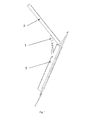
- Fig. 1 shows the turn stop in the exploded view.
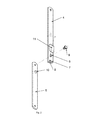
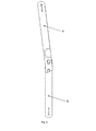
- Fig. 3 shows the turn stop in the fully open position before interlocking, while Fig. 4 shows the turn stop in the interlocked position.
- the turn stop 1, restricting and interlocking the rotary motion of the tilt member 2 against the fixed frame 3, consists of two rigid members made advantageously of a flat bar - connecting member 4 and connecting member 5 - joint together in a pivoting-sliding manner with a yoke coupling.
- the first connecting member 4 has an hole at one end, which is used for pivoting connection to the fixed frame 3 or the tilt member 2, depending on the selected interlocking direction.
- this connecting member 4 has a yoke guide 6 made angularly, at the ⁇ angle in relation to the axis of this connecting member 4, and the socket 7 made in the extension of this connecting member 4.
- One of the edges of the socket 7 is extended and performs the function of the bearing surface 8.
- the second connecting member 5 like the first one 4, at one end has a hole for pivoting connection to the fixed frame 3 or the tilt member 2.
- the second connecting member 5 has a pivot 9 mating in a pivoting-sliding manner the guide yoke 6.
- the mutual position of the pivot 9 and the yoke guide 6 defines the axis of rotation of the connecting members against each other.
- a lock is used for complete interlocking of the common turn of the connecting members, comprising a socket 7 made in the first connecting member 4, and a mandrel 10 placed between the pivot 9 and the pivoting node of the second connecting member 5, that is the hole at its other end, at a distance matching the distance between the socket 8 and the yoke guide 6 in the first connecting member 4.
- the design of the turn stop allows the connecting members to make a straight angle mutual turn around the axis of the pivot 9 in the non-interlocking direction. It means the connecting members from the fully open position, shown in Fig. 3 , may turn 180°, to the folded position, not shown in the drawings. However, in the opposite direction, the mutual rotation of the connecting members from the position acc. to Fig. 3 is restricted by the bearing surface 8, which limits the arcwise travel of the mandrel 10 around the axis of the pivot 9, whose relative position defines the maximum angle of deflection of the connecting members against each other.
- Locking or interlocking of the turn of stop in both directions, occurs after the mutual pushing together of the connecting members has been forced, by applying a force to their outer pivoting nodes, which takes place while closing the tilt member 2.
- the application of the yoke guide 6 enables the mandrel 10 to be put into the socket 7 and the relative turn of the connecting members to be fully interlocked.
- the pivot 9 will move to the other end of the yoke guide 6, a rigid system will form, fully interlocking any mutual turn of the connecting members.
- angular (angle a) arrangement of the axis of the yoke guide 6 against the axis of the first connecting member 4 causes, with the aid of even a small torque, resulting e.g. from the resultant gravity forces of the connecting members, automatic setting of the turn stop 1 in the interlocked position. It is unlocked after mutual parting of the connecting members.
- Such a functionality of the turn stop 1 enables it to be safely used e.g. in pivot roof windows or roof hatch flaps, where the centre of mass of the tilt member 2 is below its axis of rotation, in other words the tilt member is opened upwards. In such a case interlocking of the tilt member in the open position is automatic, and its unlocking and possibility of closing occurs after its maximum deflection.
- the turn stop 1 In this position of the tilt member 2, the turn stop 1 is in the fully open position, as shown in Fig. 3 . Unlocking of the turn stop 1 and enabling of the closing of the tilt member 2, only possible in this position of the turn stop, occurs after manual initiating of its turn in the direction opposite to the interlocking direction. The complete folding of the stop is possible due to the rib 11, which enables the mandrel 10 to be put into the vacated space without affecting the mechanical strength of the first connecting member 4.
Landscapes
- Engineering & Computer Science (AREA)
- Mechanical Engineering (AREA)
- Pivots And Pivotal Connections (AREA)
Abstract
Roof or façade structure tilt member opening stop, connected pivotably to the fixed frame with a non-vertical axis of rotation, with the torque acting towards closing, interlocking the turn of the tilt member in the open position in both directions, with operation based on the scissor-like folding of two rigid connecting members joint together movably on a pivot mating the guide, forming a flat kinematic system, with one connecting member connected rotationally to the fixed frame and another connecting member connected rotationally to the tilt member which opening stop has the yoke guide (6), situated in the first connecting member (4), which is mated by the pivot (9) mounted in the other connecting member (5) forming together a pivoting-sliding kinematic couple, has a longitudinal axis placed angularly, at an angle (α) against the longitudinal axis of its connecting member (4).
Description
- The invention concerns a roof or façade structure tilt member opening stop, limiting the opening of the tilt member with a horizontal or near horizontal axis of rotation, for instance of a pivot window sash or a roof hatch flap. The stop arrangement is a flat kinematic system, perpendicular to the axis of rotation of the tilt member. Its operation is based on the scissor-like folding of two advantageously flat connecting members, joint together in a pivoting or pivoting-sliding manner, during the closing movement, and unfolding during the opening movement. Both connecting members are simultaneously secured to the opposite ends also in a pivoting manner - one to the fixed frame structure, e.g. a window frame, the other one to the tilt member profile.
- Assuming a horizontal or in specific cases any non-plumb axis of rotation of the tilt member - the force of gravitation causes a torque dependent on the position of the centre of mass against the axis of rotation. If the centre of mass of the tilt member is located above the axis, the torque acts towards its opening. In this case, known solutions, described in the prior art section, perform their function well. However, if the centre of mass of the tilt member is located below the axis, the torque acts towards its closing and the stop should have its structure rigid enough to ensure the tilt element is held in the open position.
- A solution of the opening stop consisting of two rods connected together like scissors is known from
DE 42 25 328 . One of the rods is secured in a pivoting-sliding manner with one end to the window sash frame, while the other one is movably connected to the fixed window frame and fitted at its end with a profiled hook. While opening the window, both rods unfold like scissors until they are set in the maximum position limited with elastically overlapping projections, situated at the ends of both rods. While closing the window, the rods overcome the friction force occurring between the projections and at the same time one rod moves with its socket on a mandrel mounted on the window fixed frame and the other one moves with its mandrel in a socket situated in the window sash frame until the window has been fully closed. - Also a solution to be used as an opening and closing stop, in particular of a façade window, is known from
WO 9631676 - Also solutions of simple scissor-like stops without additional position interlocking members are known from the market. Such solutions are used mainly where the location of the tilt member ensures the torque, caused e.g. by the gravity force or an additional spring, acts towards opening.
- Also solutions used where the torque resulting from the gravitational force acts on the tilt member towards closing are known. The stop design is based on two connecting members joint together, and respectively to the fixed frame and to the tilt member, pivotably. The operation of the scissor-like opening stop is based on the possibility of free turn of the connecting members against each other, from the initial condition, only in one direction. The initial condition of the arrangement, determined by the dead centre, means the connecting members are in the unfolded position parallel to each other. The mutual rotation of the connecting members in the opposite direction is restricted by a simple interlocking member. Most often it is an additional mandrel or bent projection belonging to one of the connecting members. The location of the interlocking member defines the maximum angle of deflection of the connecting members against each other. A solution like this has two functions - limiting the maximum opening of the tilt member and supporting it in the open position. Manual operation of opening of the tilt member and its interlocking in this position is limited to full opening of the tilt member, and subsequently initiating the mutual turn of the connecting members in the interlocking direction. However, a position like this is little stable and depends on the continuous effect of force caused by the tilt member. In addition, even accidental catch of the arrangement may cause the connecting members to go over the dead centre and the tilt member to close completely in an uncontrolled manner.
- The objective of the proposed solution is to introduce a scissor-like opening stop, whose design ensures the tilt member automatically interlocks and remains in the open position, in particular in the case of the torque acting on the tilt member in the closing direction. In addition, the opening stop design should ensure the turn of the tilt member can be easily unlocked when closing, and it is protected against uncontrolled unlocking.
- The essence of the invention is the rotation stop mechanism design supporting mechanically the rotation of the connecting members against each other in the interlocking direction. It occurs during the closing movement of the tilt member from the maximum open position, where the connecting members are parallel to each other. The arrangement can also be unlocked by re-opening of the tilt member to its maximum position, and next simultaneous closing of the sash and manual initiation of the mutual rotation of the connecting members of the arrangement in the direction opposite to the interlocking direction.
- The opening stop is a flat kinematic system comprising two rigid connecting members connected together in a pivoting-sliding manner on a pivot mating a yoke guide. The other node of each connecting member is pivotably connected respectively to the fixed frame or to the tilt member. A system like this has two degrees of freedom.
- According to the invention, the yoke guide, situated in the first connecting member, mating the pivot mounted on the other connecting member, forming together a pivoting-sliding kinematic couple, has its longitudinal axis situated angularly, at the α angle against the longitudinal axis of its connecting member. In addition, the rotation stop has a lock, comprising a socket made on the extension of one of the connecting members, advantageously the member with the yoke guide and a mandrel mounted at the other connecting member. The mandrel is placed between the connecting member nodes, e.i. between the pivot and the point of securing to the fixed frame or the tilt member, at a distance corresponding to the distance between the socket and the yoke guide in the other connecting member. The mandrel has its axis advantageously parallel to the pivot axis.
- The socket performs two functions - with the bearing surface it restricts the maximum angle between the connecting members in the interlocking direction of the rotation stop and it interlocks the mutual rotation of the connecting members against each other in this position.
- The first connecting member has at its free end the bearing surface restricting the mandrel movement in the direction interlocking the turn. The geometrical centre of the socket does not coincide with the axis of its connecting member.
- In the interlocked position, the axis of the first connecting member is not parallel to the axis of the other one.
- When the tilt member is closed, the scissor-like turn stop is folded, in addition the angle between the connecting members in this condition can have any value, depending on the designed opening angle of the tilt member and design parameters of the stop itself. While opening the tilt member, the angle between the connecting members increases until it reaches the straight angle at the maximum opening of the tilt member. In this position the stop interlocks any further turn of the tilt member, acting like a tension member holding the tilt member when the torque is acting towards its opening.
- However, if the turn stop performs also a supporting function, i.e. interlocking the closing when the torque acts towards its closing, then the tilt member is automatically interlocked after the return travel has been initiated. In the maximum open position of the tilt member, the turn stop connecting members are in the obtuse position parallel to each other, the pivot is located in the end part of the yoke guide, and the mandrel is extended from the socket. In this position the mutual turn of the connecting members is possible in one direction, not interlocking, by any angle (even up to 180°) resulting from the design specificity, and the tilt member may be freely closed. In the other direction, interlocking, the mutual turn of the connecting members is interlocked by the bearing surface at one connecting member, which restricts the movement of the mandrel mounted at the other one. The relative position of the bearing surface and the mandrel defines the maximum angle of deflection of the connecting members against each other.
- To interlock the stop turn in the other direction, which is the fundamental objective of this invention, the connecting members should be positively pushed together by applying a force to one of their outer nodes. The reaction will occur at the other node. Due to the rotary nature of these nodes, the direction of forces is always parallel to the axis of the connecting members. Moreover, the torque resulting from the gravity force with its value depending on the angle of arrangement of the stop against the plumb-line has an effect on the connecting members. This torque has the highest value for the horizontal arrangement, whereas for the ideal vertical arrangement it is equal to zero. The application of yoke guides enable the mandrel to be put into the socket and the relative turn of the connecting members to be interlocked. Because the pivot will move to the other end of the yoke guide, a rigid system will form, fully interlocking any mutual turn of the connecting members.
- When the turn stop is used in the system with a tilt member with a horizontal axis of rotation, where the fully open stop is also in the horizontal position, and its interlocking direction has a sense in line with the gravity force effect, the torque resulting from this force is strong enough for the stop to automatically interlock during closing of the tilt member.
- However, if the fully open stop is in a position other then horizontal, in extreme case close to the plumb, then the torque resulting from the gravity force is insignificant. In the case of yoke guides arranged in parallel to the axis of the connecting member, the risk of instability of the system by an uncontrolled selection of direction of the turn of the connecting members against each other is substantial. When the guides are placed at an angle to the connecting member axis, this risk is eliminated.
- The turn stop in the embodiment example, in the interlocked position secured to the tilt member and the fixed frame, is presented in
Fig. 1. Fig. 1 shows the turn stop in the exploded view.Fig. 3 shows the turn stop in the fully open position before interlocking, whileFig. 4 shows the turn stop in the interlocked position. - In the embodiment example shown in the drawings, the
turn stop 1, restricting and interlocking the rotary motion of thetilt member 2 against the fixedframe 3, consists of two rigid members made advantageously of a flat bar - connectingmember 4 and connecting member 5 - joint together in a pivoting-sliding manner with a yoke coupling. The first connectingmember 4 has an hole at one end, which is used for pivoting connection to the fixedframe 3 or thetilt member 2, depending on the selected interlocking direction. At the other end this connectingmember 4 has ayoke guide 6 made angularly, at the α angle in relation to the axis of this connectingmember 4, and thesocket 7 made in the extension of this connectingmember 4. One of the edges of thesocket 7 is extended and performs the function of the bearingsurface 8. - The second connecting
member 5, like thefirst one 4, at one end has a hole for pivoting connection to the fixedframe 3 or thetilt member 2. At the other end the second connectingmember 5 has apivot 9 mating in a pivoting-sliding manner theguide yoke 6. The mutual position of thepivot 9 and theyoke guide 6 defines the axis of rotation of the connecting members against each other. A lock is used for complete interlocking of the common turn of the connecting members, comprising asocket 7 made in the first connectingmember 4, and amandrel 10 placed between thepivot 9 and the pivoting node of the second connectingmember 5, that is the hole at its other end, at a distance matching the distance between thesocket 8 and theyoke guide 6 in the first connectingmember 4. - The design of the turn stop allows the connecting members to make a straight angle mutual turn around the axis of the
pivot 9 in the non-interlocking direction. It means the connecting members from the fully open position, shown inFig. 3 , may turn 180°, to the folded position, not shown in the drawings. However, in the opposite direction, the mutual rotation of the connecting members from the position acc. toFig. 3 is restricted by the bearingsurface 8, which limits the arcwise travel of themandrel 10 around the axis of thepivot 9, whose relative position defines the maximum angle of deflection of the connecting members against each other. Locking, or interlocking of the turn of stop in both directions, occurs after the mutual pushing together of the connecting members has been forced, by applying a force to their outer pivoting nodes, which takes place while closing thetilt member 2. The application of theyoke guide 6 enables themandrel 10 to be put into thesocket 7 and the relative turn of the connecting members to be fully interlocked. Thepivot 9 will move to the other end of theyoke guide 6, a rigid system will form, fully interlocking any mutual turn of the connecting members. - The use of angular (angle a) arrangement of the axis of the
yoke guide 6 against the axis of the first connectingmember 4 causes, with the aid of even a small torque, resulting e.g. from the resultant gravity forces of the connecting members, automatic setting of the turn stop 1 in the interlocked position. It is unlocked after mutual parting of the connecting members. Such a functionality of the turn stop 1 enables it to be safely used e.g. in pivot roof windows or roof hatch flaps, where the centre of mass of thetilt member 2 is below its axis of rotation, in other words the tilt member is opened upwards. In such a case interlocking of the tilt member in the open position is automatic, and its unlocking and possibility of closing occurs after its maximum deflection. In this position of thetilt member 2, the turn stop 1 is in the fully open position, as shown inFig. 3 . Unlocking of the turn stop 1 and enabling of the closing of thetilt member 2, only possible in this position of the turn stop, occurs after manual initiating of its turn in the direction opposite to the interlocking direction. The complete folding of the stop is possible due to therib 11, which enables themandrel 10 to be put into the vacated space without affecting the mechanical strength of the first connectingmember 4.
Claims (6)
- Roof or façade structure tilt member opening stop, connected pivotably to the fixed frame with a non-vertical axis of rotation, with the torque acting towards closing, interlocking the turn of the tilt member in the open position in both directions, with operation based on the scissor-like folding of two rigid connecting members joint together movably on a pivot mating the guide, forming a flat kinematic system, with one connecting member connected rotationally to the fixed frame and another connecting member connected rotationally to the tilt member, characterised in that the yoke guide (6), situated in the first connecting member (4), which is mated by the pivot (9) mounted in the other connecting member (5) forming together a pivoting-sliding kinematic couple, has a longitudinal axis placed angularly, at an angle (α) against the longitudinal axis of its connecting member (4).
- Opening stop as claimed in claim 1, characterised in that one of the connecting members (4), (5) has a mandrel (10) with the axis advantageously parallel to the axis of the pivot (9), and respectively the other connecting member (4), (5) has in its extension a recess forming a socket (7) for the mandrel. (10).
- Opening stop as claimed in claim 2, characterised in that the other connecting member (5), has a mandrel (10) with its axis advantageously parallel to the axis of the pivot (9), and the first connecting member (4) with a yoke guide (6) has in its extension a recess forming a socket (7) for the mandrel. (10).
- Opening stop as claimed in claim 2, characterised in that the connecting member (4), (5) with the yoke guide (6) has at its free end a bearing surface (8) restricting movement of the mandrel (10) in the direction interlocking the turn.
- Opening stop as claimed in claim 2 or 3 or 4, characterised in that the geometrical centre of the socket (7) does not coincide with the axis of the first connecting member (4).
- Opening stop as claimed in claim 1 characterised in that in the interlocked position the axis of the first connecting member (4) is not parallel to the axis of the other one (5).
Applications Claiming Priority (1)
| Application Number | Priority Date | Filing Date | Title |
|---|---|---|---|
| PL391944A PL217313B1 (en) | 2010-07-26 | 2010-07-26 | Tilt limiter of a tilting element of the roof or facade structure |
Publications (1)
| Publication Number | Publication Date |
|---|---|
| EP2412904A2 true EP2412904A2 (en) | 2012-02-01 |
Family
ID=44543065
Family Applications (1)
| Application Number | Title | Priority Date | Filing Date |
|---|---|---|---|
| EP20110175382 Withdrawn EP2412904A2 (en) | 2010-07-26 | 2011-07-26 | Roof or facade structure tilt member opening stop |
Country Status (2)
| Country | Link |
|---|---|
| EP (1) | EP2412904A2 (en) |
| PL (1) | PL217313B1 (en) |
Families Citing this family (1)
| Publication number | Priority date | Publication date | Assignee | Title |
|---|---|---|---|---|
| CN106193853B (en) * | 2016-06-27 | 2017-08-04 | 杭州西力智能科技股份有限公司 | A kind of chamber door angle control structure of the nonmetallic low-pressure metering box of single-phase multi-epitope |
Citations (2)
| Publication number | Priority date | Publication date | Assignee | Title |
|---|---|---|---|---|
| DE4225328A1 (en) | 1992-07-31 | 1994-02-03 | Bilstein August Gmbh Co Kg | Rabbet scissors mechanism for window or door tilting leaf - has two hinged scissors rods hinged to fixed and leaf frames via lock member or fastening rail |
| WO1996031676A1 (en) | 1995-04-05 | 1996-10-10 | Interlock Industries Limited | A restrictor device |
-
2010
- 2010-07-26 PL PL391944A patent/PL217313B1/en unknown
-
2011
- 2011-07-26 EP EP20110175382 patent/EP2412904A2/en not_active Withdrawn
Patent Citations (2)
| Publication number | Priority date | Publication date | Assignee | Title |
|---|---|---|---|---|
| DE4225328A1 (en) | 1992-07-31 | 1994-02-03 | Bilstein August Gmbh Co Kg | Rabbet scissors mechanism for window or door tilting leaf - has two hinged scissors rods hinged to fixed and leaf frames via lock member or fastening rail |
| WO1996031676A1 (en) | 1995-04-05 | 1996-10-10 | Interlock Industries Limited | A restrictor device |
Also Published As
| Publication number | Publication date |
|---|---|
| PL391944A1 (en) | 2012-01-30 |
| PL217313B1 (en) | 2014-07-31 |
Similar Documents
| Publication | Publication Date | Title |
|---|---|---|
| AU2016349105B2 (en) | A hinge for a roof window, and a roof window including a set of hinges | |
| US9777509B2 (en) | Flush lock for casement window and method of operating the same | |
| KR200477585Y1 (en) | Handle device for window and door system | |
| JP5395732B2 (en) | window | |
| CN104246099B (en) | Swing closing device for door, window or the like | |
| EP3714125B1 (en) | Roof window with a primary frame and at least one secondary frame, method for installing such a roof window and method for dismantling a secondary frame of the roof window | |
| WO2014201373A1 (en) | Accordion shutter hinge assembly | |
| EP2412904A2 (en) | Roof or facade structure tilt member opening stop | |
| EP2385203A1 (en) | Locking hinge | |
| CN109914950B (en) | Window lock and window based on window lock | |
| EP2728216A2 (en) | Telescopic spring unit with a control device | |
| CN103321509A (en) | Opening-closing device of multifunctional window | |
| US20160060941A1 (en) | Coaxially Extending Arm for Door Closing Operator | |
| CN114370206A (en) | Sliding support and door and window with same | |
| KR200416599Y1 (en) | The safety device of windows and doors system for opening shutting the upper direction | |
| EP2762665B1 (en) | A pivot hinge fitting with engagement means and a roof window comprising a set of such pivot hinge fittings | |
| CZ293782B6 (en) | Telescopic window spacer | |
| US20130192027A1 (en) | Articulated shutter holder | |
| CN215293337U (en) | Bidirectional stop pawl assembly and ratchet mechanism | |
| CN217233170U (en) | Sliding support and door and window with same | |
| KR100865772B1 (en) | Stay assembly for windows and doors system of opening and shutting the upper direction | |
| JP3973030B2 (en) | Shutter | |
| US1030115A (en) | Fastening device for storm-windows or the like. | |
| JPS5931886Y2 (en) | Sealing unit sealing device | |
| EP4308775A1 (en) | Hinged joint and method of use |
Legal Events
| Date | Code | Title | Description |
|---|---|---|---|
| AK | Designated contracting states |
Kind code of ref document: A2 Designated state(s): AL AT BE BG CH CY CZ DE DK EE ES FI FR GB GR HR HU IE IS IT LI LT LU LV MC MK MT NL NO PL PT RO RS SE SI SK SM TR |
|
| AX | Request for extension of the european patent |
Extension state: BA ME |
|
| PUAI | Public reference made under article 153(3) epc to a published international application that has entered the european phase |
Free format text: ORIGINAL CODE: 0009012 |
|
| 17P | Request for examination filed |
Effective date: 20130205 |
|
| STAA | Information on the status of an ep patent application or granted ep patent |
Free format text: STATUS: THE APPLICATION HAS BEEN WITHDRAWN |
|
| 18W | Application withdrawn |
Effective date: 20130430 |