EP2412898A1 - Electronic lock - Google Patents
Electronic lock Download PDFInfo
- Publication number
- EP2412898A1 EP2412898A1 EP20100755610 EP10755610A EP2412898A1 EP 2412898 A1 EP2412898 A1 EP 2412898A1 EP 20100755610 EP20100755610 EP 20100755610 EP 10755610 A EP10755610 A EP 10755610A EP 2412898 A1 EP2412898 A1 EP 2412898A1
- Authority
- EP
- European Patent Office
- Prior art keywords
- section
- case
- electronic lock
- opening
- mobile device
- Prior art date
- Legal status (The legal status is an assumption and is not a legal conclusion. Google has not performed a legal analysis and makes no representation as to the accuracy of the status listed.)
- Withdrawn
Links
- 238000003780 insertion Methods 0.000 claims abstract description 37
- 230000037431 insertion Effects 0.000 claims abstract description 37
- 239000011347 resin Substances 0.000 description 12
- 229920005989 resin Polymers 0.000 description 12
- 238000000465 moulding Methods 0.000 description 7
- 238000000034 method Methods 0.000 description 6
- 238000012856 packing Methods 0.000 description 4
- 238000007796 conventional method Methods 0.000 description 3
- 238000004891 communication Methods 0.000 description 2
- 238000004519 manufacturing process Methods 0.000 description 2
- 239000000853 adhesive Substances 0.000 description 1
- 230000001070 adhesive effect Effects 0.000 description 1
- 230000000694 effects Effects 0.000 description 1
- 239000000463 material Substances 0.000 description 1
Images



Classifications
-
- G—PHYSICS
- G07—CHECKING-DEVICES
- G07C—TIME OR ATTENDANCE REGISTERS; REGISTERING OR INDICATING THE WORKING OF MACHINES; GENERATING RANDOM NUMBERS; VOTING OR LOTTERY APPARATUS; ARRANGEMENTS, SYSTEMS OR APPARATUS FOR CHECKING NOT PROVIDED FOR ELSEWHERE
- G07C9/00—Individual registration on entry or exit
- G07C9/00174—Electronically operated locks; Circuits therefor; Nonmechanical keys therefor, e.g. passive or active electrical keys or other data carriers without mechanical keys
- G07C9/00944—Details of construction or manufacture
-
- E—FIXED CONSTRUCTIONS
- E05—LOCKS; KEYS; WINDOW OR DOOR FITTINGS; SAFES
- E05B—LOCKS; ACCESSORIES THEREFOR; HANDCUFFS
- E05B19/00—Keys; Accessories therefor
- E05B19/0082—Keys or shanks being removably stored in a larger object, e.g. a remote control or a key fob
-
- E—FIXED CONSTRUCTIONS
- E05—LOCKS; KEYS; WINDOW OR DOOR FITTINGS; SAFES
- E05B—LOCKS; ACCESSORIES THEREFOR; HANDCUFFS
- E05B19/00—Keys; Accessories therefor
- E05B19/04—Construction of the bow or head of the key; Attaching the bow to the shank
- E05B19/046—Construction of the bow or head of the key; Attaching the bow to the shank the shank being slidingly mounted on the bow, e.g. for storage
-
- G—PHYSICS
- G07—CHECKING-DEVICES
- G07C—TIME OR ATTENDANCE REGISTERS; REGISTERING OR INDICATING THE WORKING OF MACHINES; GENERATING RANDOM NUMBERS; VOTING OR LOTTERY APPARATUS; ARRANGEMENTS, SYSTEMS OR APPARATUS FOR CHECKING NOT PROVIDED FOR ELSEWHERE
- G07C9/00—Individual registration on entry or exit
- G07C9/00174—Electronically operated locks; Circuits therefor; Nonmechanical keys therefor, e.g. passive or active electrical keys or other data carriers without mechanical keys
- G07C2009/00968—Electronically operated locks; Circuits therefor; Nonmechanical keys therefor, e.g. passive or active electrical keys or other data carriers without mechanical keys shape of the data carrier
- G07C2009/00984—Electronically operated locks; Circuits therefor; Nonmechanical keys therefor, e.g. passive or active electrical keys or other data carriers without mechanical keys shape of the data carrier fob
-
- Y—GENERAL TAGGING OF NEW TECHNOLOGICAL DEVELOPMENTS; GENERAL TAGGING OF CROSS-SECTIONAL TECHNOLOGIES SPANNING OVER SEVERAL SECTIONS OF THE IPC; TECHNICAL SUBJECTS COVERED BY FORMER USPC CROSS-REFERENCE ART COLLECTIONS [XRACs] AND DIGESTS
- Y10—TECHNICAL SUBJECTS COVERED BY FORMER USPC
- Y10T—TECHNICAL SUBJECTS COVERED BY FORMER US CLASSIFICATION
- Y10T70/00—Locks
- Y10T70/70—Operating mechanism
- Y10T70/7441—Key
- Y10T70/778—Operating elements
- Y10T70/7791—Keys
- Y10T70/7802—Multi-part structures
- Y10T70/7831—Nested second key
-
- Y—GENERAL TAGGING OF NEW TECHNOLOGICAL DEVELOPMENTS; GENERAL TAGGING OF CROSS-SECTIONAL TECHNOLOGIES SPANNING OVER SEVERAL SECTIONS OF THE IPC; TECHNICAL SUBJECTS COVERED BY FORMER USPC CROSS-REFERENCE ART COLLECTIONS [XRACs] AND DIGESTS
- Y10—TECHNICAL SUBJECTS COVERED BY FORMER USPC
- Y10T—TECHNICAL SUBJECTS COVERED BY FORMER US CLASSIFICATION
- Y10T70/00—Locks
- Y10T70/70—Operating mechanism
- Y10T70/7441—Key
- Y10T70/778—Operating elements
- Y10T70/7791—Keys
- Y10T70/7876—Bow or head
-
- Y—GENERAL TAGGING OF NEW TECHNOLOGICAL DEVELOPMENTS; GENERAL TAGGING OF CROSS-SECTIONAL TECHNOLOGIES SPANNING OVER SEVERAL SECTIONS OF THE IPC; TECHNICAL SUBJECTS COVERED BY FORMER USPC CROSS-REFERENCE ART COLLECTIONS [XRACs] AND DIGESTS
- Y10—TECHNICAL SUBJECTS COVERED BY FORMER USPC
- Y10T—TECHNICAL SUBJECTS COVERED BY FORMER US CLASSIFICATION
- Y10T70/00—Locks
- Y10T70/80—Parts, attachments, accessories and adjuncts
- Y10T70/8432—For key-operated mechanism
- Y10T70/8676—Key holders
Definitions
- the present invention relates to an electronic lock with a mechanical lock, for use in a remote control system for opening and closing a door.
- a remote control system using an electronic lock is mounted in a vehicle.
- This remote control system locks and/or unlocks a door of a vehicle in a non-contact manner, by performing wireless communication between a control unit mounted in the vehicle, and an electronic lock which a user carries.
- An electronic lock is carried outside a vehicle by a user, and therefore needs be water-proof and dust-proof to prevent the inner electronic circuitry from failing.
- providing in an electronic lock a mechanical lock for locking and/or unlocking a door of a vehicle mechanically is being studied (see, for example, patent literature 1).
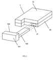
- FIG.1 shows a conventional electronic lock provided with a mechanical lock.
- the electronic lock has mobile device 1 and mechanical lock 100.
- Mobile device 1 is covered by upper case 10 and lower case 20, and insertion section 21 is formed in lower case 20.
- Mechanical lock 100 is comprised of holding section 101 and bar-shaped section 102. This bar-shaped section 102 is inserted in insertion section 21 in a removable fashion.
- the shape of insertion section 21 needs to be formed a saclike shape inside mobile device 1.
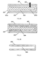
- FIG.2A illustrates the first step of a conventional molding method of forming insertion section 21 shown in FIG.1 .
- FIG.2B illustrates a second step of a conventional molding method of forming insertion section 21 shown in FIG.1 .
- FIG.2C illustrates a third step of a conventional molding method of forming insertion section 21 shown in FIG.1 .
- the direction from the left to the right in the drawing is the direction of insertion of mechanical lock 100 into mobile device 1.
- first metallic mold 201, second metallic mold 202 and third metallic mold 203 are fitted together so as to form space 204 for pouring in resin.
- an opening for pouring resin in space 204 is formed in a left part of second metallic mold 202 in contact with third metallic mold 203 in the drawing.
- Third metallic mold 203 is comprised of base section 203a that fits together with first metallic mold 201 and second metallic mold 202, and projecting section 203b that extends from base section 203a to the right in this drawing in a pointing shape.
- the shape of this projecting section 203b is approximately the same as the shape of bar-shaped section 102 of mechanical lock 100, and is long along the insertion direction and thin.
- first metallic mold 201, second metallic mold 202 and third metallic mold 203 are taken apart, and insertion section 21 comprised of frame body 208 and opening section 209 is formed.
- An electronic lock comprises a mobile device that incorporates an electric circuit that wireless-communicates with the outside and locks and/or unlocks a door, and a mechanical lock that can be attached to the mobile device in a removable fashion and that locks and/or unlocks the door mechanically, and, in this electronic lock, the mobile device comprises: a case, in which the electric circuit is accommodated; an inner case which is provided in the case and in which the electric circuit is placed; an insertion section, which is provided in the case, in which the mechanical lock can be inserted from a front end section, and which has an opening section in an upper surface of a terminal end section; and a cover section that is fitted in the opening section in the insertion section.
- the present invention upon forming an insertion section for a mechanical lock in an electronic lock, a step of pouring in resin for a second time is not necessary, and a special molding tool for pulling out only a press pin while maintaining first metallic mold 201 and second metallic mold 202 closed, is not necessary. Consequently, the present invention is able to provide an electronic lock that reduces the time for manufacturing and improves productivity while maintaining water-proofness.
- FIG.3 is an exploded perspective view of mobile device 1 in an electronic lock according to embodiment 1 of the present invention.
- mobile device 1 is comprised of upper case 10, lower case 20, inner case 30 and packing 40.
- Upper case 10 is coupled with lower case 20, and accommodates inner case 30 and packing 40 inside.
- Insertion section 21, in which a bar-shaped section (which is in FIG.2 bar-shaped section 102) of a mechanical lock (which is in FIG.2 mechanical lock 100) can be inserted is formed from the front end section to the terminal end section of lower case 20 along the y-axis direction in FIG.3 .
- opening section 23 is provided in a terminal end section. This opening section 23 is closed by fitting in rubber member 24.
- lower case 20 has lowered section 25 that is dented in the z axis direction from upper surface 22 of insertion section 21.
- projecting section 26 is raised in the z axis direction and encloses upper surface 22 of insertion section 21 and lowered section 25. With this projecting section 26, upper surface 22 of insertion section 21 and lowered section 25 form a recess.
- Inner case 30 has projecting section 31 to be placed over lowered section 25.
- Inner case 30 has step section 32, which is lower than projecting section 31 in height in the z axis direction. This step section 32 is placed over upper surface 22 of insertion section 21. Also, opening sections 33 are provided in the upper surface of inner case 30. Piezoelectric sensor 34 and key switch 35 connected on this piezoelectric sensor 34 stick out from each opening section 33.
- FIG.4 is a plan view showing the back surface of inner case 30 of FIG.3 along the z axis direction. Opening sections 36 are provided on the step section 32 side of inner case 30. From each opening section 36, electric circuit 37 incorporated inside inner case 30 is exposed. Also, on the projecting section 31 side of inner case 30, battery 38 for driving electric circuits 37 is provided. Battery 38 is fixed by means of holding sections 39. When key switches 35 are pressed, electric circuits 37 detect this via piezoelectric sensors 34, and perform a process for locking and/or unlocking a door.
- Packing 40 is formed by a rubber material, and has: main body section 41 that is placed over inner case 30; flange section 42 that overhangs from the outer periphery of main body section 41 in x-y plane directions; and projecting sections 43 that project from the upper surface of main body section 41 and are placed over key switches 35.
- the lower surface of this flange section 42 contacts the upper surface of projecting section 26.
- FIG.5 is a cross sectional view of mobile device 1 cutting mobile device 1 along an x-z plane passing rubber member 24, seen along the positive y axis direction.
- projecting sections 11 provided in lower surfaces on outer peripheries of upper case 10, and mounting sections 27 formed on the periphery side of projecting sections 26 of lower case 20.
- mobile device 1 is sealed tight from outside.
- the lower surfaces of flange sections 42 of packing 40 are placed upon projecting sections 26, and step sections 12, provided on the inner periphery side of projecting sections 11 of upper case 10, fit with upper surfaces of flange sections 42. By this means, the liquid-tightness of electric circuits 37 in inner case 30 is guaranteed.
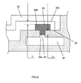
- FIG.6 is an enlarged view of an area around rubber member 24 of FIG.5 .
- rubber member 24 has bar-shaped section 24a and flange sections 24b that overhang from the upper end side of bar-shaped section 24a to the outer periphery side.
- Bar-shaped section 24a is fitted in opening section 23 in upper surface 22 of insertion section 21.
- the lower surfaces of flange sections 24b contact upper surface 22 of insertion section 21.
- height t 1 of the space from lower surface 32a of step section 32 to the upper surface of flange sections 24b is lower than height t 2 from upper surface 22 of insertion section 21 to the lower surface of bar-shaped section 24a.
- the present invention is equally applicable to an electronic lock for different usage, such as opening and closing a door of a house.
- Embodiment 2 of the present invention will be described now. Parts that are the same as in embodiment 1 of the present invention will be assigned the same reference codes and their explanations will be omitted.
- FIG.7 is an enlarged view of an area around rubber member 24 according to embodiment 2, and corresponds to FIG.6 .
- edge sections 22a that project upward are formed on perimeter edges of opening section 23. These edge sections 22a can guide rubber member 24. Consequently, it is possible to fit rubber member 24 in opening section 23 provided in upper surface 22 of insertion section 21 at ease.
- the electronic lock of the present invention is suitable for use as an electronic lock with a mechanical lock to use in a remote control system for, for example, opening and closing a door of a vehicle or house.
Landscapes
- Engineering & Computer Science (AREA)
- Manufacturing & Machinery (AREA)
- Physics & Mathematics (AREA)
- General Physics & Mathematics (AREA)
- Lock And Its Accessories (AREA)
Abstract
Provided is an electronic lock which achieves improved productivity while maintaining the performance of waterproofness for an internal electronic circuit of an insertion portion for a mechanical lock. Specifically provided is an electronic lock provided with a portable machine (1) which contains an electric circuit that locks and/or unlocks a door by communicating with the outside wirelessly, and a mechanical lock which is attachable to and detachable from the portable machine (1) and mechanically locks and/or unlocks the door. In the electronic lock, the portable machine (1) comprises: an upper case (10) and a lower case (20) which house the electric circuit; an inner case (30) within the upper case (10) and lower case (20), in which the electric circuit is disposed; an insertion portion (21) within the lower case (20), into which the mechanical lock is insertable from the front end thereof and which has an opening (23) in the upper surface (22) at the terminal end thereof; and a rubber member (24) which is inserted into the opening (23) of the insertion portion (21).
Description
- The present invention relates to an electronic lock with a mechanical lock, for use in a remote control system for opening and closing a door.
- These years, a remote control system using an electronic lock is mounted in a vehicle. This remote control system locks and/or unlocks a door of a vehicle in a non-contact manner, by performing wireless communication between a control unit mounted in the vehicle, and an electronic lock which a user carries. An electronic lock is carried outside a vehicle by a user, and therefore needs be water-proof and dust-proof to prevent the inner electronic circuitry from failing. In addition, considering an emergency case where the electronic circuitry inside an electronic lock cannot perform wireless communication, providing in an electronic lock a mechanical lock for locking and/or unlocking a door of a vehicle mechanically, is being studied (see, for example, patent literature 1).
-
FIG.1 shows a conventional electronic lock provided with a mechanical lock. As shown inFIG.1 , the electronic lock hasmobile device 1 andmechanical lock 100.Mobile device 1 is covered byupper case 10 andlower case 20, andinsertion section 21 is formed inlower case 20.Mechanical lock 100 is comprised ofholding section 101 and bar-shaped section 102. This bar-shaped section 102 is inserted ininsertion section 21 in a removable fashion. Given the requirement to make the electronic circuitry insidemobile device 1 water-proof and dust-proof, the shape ofinsertion section 21 needs to be formed a saclike shape insidemobile device 1. -
FIG.2A illustrates the first step of a conventional molding method of forminginsertion section 21 shown inFIG.1 .FIG.2B illustrates a second step of a conventional molding method of forminginsertion section 21 shown inFIG.1 .FIG.2C illustrates a third step of a conventional molding method of forminginsertion section 21 shown inFIG.1 . InFIG.2 , the direction from the left to the right in the drawing is the direction of insertion ofmechanical lock 100 intomobile device 1. - First, as shown in
FIG.2A , firstmetallic mold 201, secondmetallic mold 202 and thirdmetallic mold 203 are fitted together so as to formspace 204 for pouring in resin. Here, although not illustrated, an opening for pouring resin inspace 204 is formed in a left part of secondmetallic mold 202 in contact with thirdmetallic mold 203 in the drawing. Thirdmetallic mold 203 is comprised ofbase section 203a that fits together with firstmetallic mold 201 and secondmetallic mold 202, and projectingsection 203b that extends frombase section 203a to the right in this drawing in a pointing shape. - The shape of this
projecting section 203b is approximately the same as the shape of bar-shaped section 102 ofmechanical lock 100, and is long along the insertion direction and thin. By this means, when resin is poured inspace 204, the resin flows in the lower part ofspace 204 in the drawing, toward the right in the drawing, which is the direction of insertion ofmechanical lock 100. Then, when the resin reaches the right end ofspace 204 in the drawing, the resin then flows upward inspace 204, and, upon reaching the front end, flows toward the left in the drawing, which is the direction of removal ofmechanical lock 100. The upward molding pressure produced by the flow of resin inspace 204, applies to the front end ofprojecting section 203b. To prevent the front end of thisprojecting section 203b from shaking, presspin 205 presses against projectingsection 203b from above. - Next, as shown in
FIG.2B , beforeresin 206 poured in the configuration ofFIG.2A solidifies completely,press pin 205 is pulled out up to the inner wall surface of firstmetallic mold 201 using a special cylinder, while maintaining firstmetallic mold 201 and secondmetallic mold 202 closed. Then, in the part of firstmetallic mold 201 from whichpress pin 205 has been pulled out, resin is poured again. Finally, as shown inFIG.2C , firstmetallic mold 201, secondmetallic mold 202 and thirdmetallic mold 203 are taken apart, andinsertion section 21 comprised offrame body 208 andopening section 209 is formed. -
- PTL 1: Japanese Patent Application Laid-Open No.
2008-25145 - However, with a conventional technique, the step of pouring resin for a second time in the part in
space 204 wherepress pin 205 has been present requires a special molding tool for pulling out only presspin 205 while maintaining firstmetallic mold 201 and secondmetallic mold 202 closed, and furthermore is time consuming. That is to say, a conventional technique has a problem with the productivity of electronic locks. - It is therefore an object of the present invention to provide an electronic lock that improves productivity while maintaining the water-proofness of inner electronic circuitry.
- An electronic lock according to the present invention comprises a mobile device that incorporates an electric circuit that wireless-communicates with the outside and locks and/or unlocks a door, and a mechanical lock that can be attached to the mobile device in a removable fashion and that locks and/or unlocks the door mechanically, and, in this electronic lock, the mobile device comprises: a case, in which the electric circuit is accommodated; an inner case which is provided in the case and in which the electric circuit is placed; an insertion section, which is provided in the case, in which the mechanical lock can be inserted from a front end section, and which has an opening section in an upper surface of a terminal end section; and a cover section that is fitted in the opening section in the insertion section.
- With the present invention, upon forming an insertion section for a mechanical lock in an electronic lock, a step of pouring in resin for a second time is not necessary, and a special molding tool for pulling out only a press pin while maintaining first
metallic mold 201 and secondmetallic mold 202 closed, is not necessary. Consequently, the present invention is able to provide an electronic lock that reduces the time for manufacturing and improves productivity while maintaining water-proofness. -
-
FIG.1 shows a conventional electronic lock with a mechanical lock; -
FIG.2 shows the first through third steps of a molding method for forming the insertion section shown inFIG.1 ; -
FIG.3 is an exploded perspective view of a mobile device in an electronic lock according toembodiment 1 of the present invention; -
FIG.4 is a plan view showing a back surface of an inner case, which is a principle part ofembodiment 1 shown inFIG.3 , along the z axis direction; -
FIG.5 is cross sectional view, showing a mobile device, which is a principle part ofembodiment 1 shown inFIG.3 , cut along an x-z plane passing a rubber member when the parts of the mobile device are assembled together, seen from the positive y axis direction; and -
FIG.6 is an enlarged view of an area around a rubber member, which is a principle part ofembodiment 1 shown inFIG.5 ; and -
FIG.7 is an enlarged view of an area around a rubber member according to embodiment 2 of the present invention. - Now, embodiments of the present invention will be described below with reference to the accompanying drawings. In the following embodiments, parts of the electronic lock of the present invention that are the same as in the conventional configuration of
FIG.1 will be assigned the same reference codes and their detailed explanations will be omitted. Also, the z axis direction is the upward direction in the drawings. -
FIG.3 is an exploded perspective view ofmobile device 1 in an electronic lock according toembodiment 1 of the present invention. As shown inFIG.3 ,mobile device 1 is comprised ofupper case 10,lower case 20,inner case 30 and packing 40. -
Upper case 10 is coupled withlower case 20, and accommodatesinner case 30 and packing 40 inside.Insertion section 21, in which a bar-shaped section (which is inFIG.2 bar-shaped section 102) of a mechanical lock (which is inFIG.2 mechanical lock 100) can be inserted is formed from the front end section to the terminal end section oflower case 20 along the y-axis direction inFIG.3 . Inupper surface 22 of thisinsertion section 21,opening section 23 is provided in a terminal end section. Thisopening section 23 is closed by fitting inrubber member 24. Also,lower case 20 has loweredsection 25 that is dented in the z axis direction fromupper surface 22 ofinsertion section 21. Furthermore, inlower case 20,projecting section 26 is raised in the z axis direction and enclosesupper surface 22 ofinsertion section 21 and loweredsection 25. With thisprojecting section 26,upper surface 22 ofinsertion section 21 and loweredsection 25 form a recess. -
Inner case 30 has projectingsection 31 to be placed over loweredsection 25.Inner case 30 hasstep section 32, which is lower than projectingsection 31 in height in the z axis direction. Thisstep section 32 is placed overupper surface 22 ofinsertion section 21. Also,opening sections 33 are provided in the upper surface ofinner case 30.Piezoelectric sensor 34 andkey switch 35 connected on thispiezoelectric sensor 34 stick out from each openingsection 33. -
FIG.4 is a plan view showing the back surface ofinner case 30 ofFIG.3 along the z axis direction. Openingsections 36 are provided on thestep section 32 side ofinner case 30. From eachopening section 36,electric circuit 37 incorporated insideinner case 30 is exposed. Also, on the projectingsection 31 side ofinner case 30,battery 38 for drivingelectric circuits 37 is provided.Battery 38 is fixed by means of holdingsections 39. When key switches 35 are pressed,electric circuits 37 detect this viapiezoelectric sensors 34, and perform a process for locking and/or unlocking a door. -
Packing 40 is formed by a rubber material, and has:main body section 41 that is placed overinner case 30;flange section 42 that overhangs from the outer periphery ofmain body section 41 in x-y plane directions; and projectingsections 43 that project from the upper surface ofmain body section 41 and are placed over key switches 35. The lower surface of thisflange section 42 contacts the upper surface of projectingsection 26. - Provided that the parts of
mobile device 1 inFIG.3 are assembled,FIG.5 is a cross sectional view ofmobile device 1 cuttingmobile device 1 along an x-z plane passingrubber member 24, seen along the positive y axis direction. As shown inFIG.5 , projectingsections 11 provided in lower surfaces on outer peripheries ofupper case 10, and mountingsections 27 formed on the periphery side of projectingsections 26 oflower case 20. By this means,mobile device 1 is sealed tight from outside. Also, the lower surfaces offlange sections 42 of packing 40 are placed upon projectingsections 26, and stepsections 12, provided on the inner periphery side of projectingsections 11 ofupper case 10, fit with upper surfaces offlange sections 42. By this means, the liquid-tightness ofelectric circuits 37 ininner case 30 is guaranteed. -
FIG.6 is an enlarged view of an area aroundrubber member 24 ofFIG.5 . As shown inFIG.6 ,rubber member 24 has bar-shapedsection 24a andflange sections 24b that overhang from the upper end side of bar-shapedsection 24a to the outer periphery side. Bar-shapedsection 24a is fitted inopening section 23 inupper surface 22 ofinsertion section 21. The lower surfaces offlange sections 24b contactupper surface 22 ofinsertion section 21. - As shown in
FIG.6 , height t1 of the space fromlower surface 32a ofstep section 32 to the upper surface offlange sections 24b, is lower than height t2 fromupper surface 22 ofinsertion section 21 to the lower surface of bar-shapedsection 24a. By this means, whenrubber member 24 is fitted inopening section 23 inupper surface 22 ofinsertion section 21, this assembling does not even require an adhesive. That is to say, even ifrubber member 24 is moved upward by pressure from theinsertion section 21 side, thedistance rubber member 24 moves upward is kept, at maximum, to height t1 when the upper surface offlange sections 24b contactlower surface 32a ofstep section 32. Then, as described above, height t2 fromupper surface 22 ofinsertion section 21 to the lower surface of bar-shapedsection 24a, is higher than height t1 of the space from the lower surface ofstep section 32 to the upper surface offlange sections 24b. Consequently, bar-shapedsection 24a is maintained in a state of being fitted in, without falling from openingsection 23 inupper surface 22 ofinsertion section 21. - With the present embodiment, upon forming
insertion section 21 inmobile device 1, compared to the conventional method illustrated inFIG.2 , it is possible to omit the process of pouring resin in opening 207 for a second time as illustrated inFIG.2B , and replace this with a step of fitting inrubber member 24. By this means, it is possible to omit a step of pulling outpress pin 205 while leaving first metallic molds 201-203. Then, first metallic molds 201-203 andpress pin 205 can be removed in the same one step, so that it is not necessary to use a special cylinder for removingonly press pin 205. Consequently, it is possible to manufacture an electronic lock, without relying upon how to control the operation, the duration of ejection and the timing of ejection with a cylinder, so that productivity can be improved by reducing the tact time, while still maintaining water-proofness. - Although a case has been described above with the present embodiment where the present invention is applied to an electronic lock for use for opening and closing a door of a vehicle, the present invention is equally applicable to an electronic lock for different usage, such as opening and closing a door of a house.
- Embodiment 2 of the present invention will be described now. Parts that are the same as in
embodiment 1 of the present invention will be assigned the same reference codes and their explanations will be omitted. -
FIG.7 is an enlarged view of an area aroundrubber member 24 according to embodiment 2, and corresponds toFIG.6 . As shown inFIG.7 , inupper surface 22 ofinsertion section 21,edge sections 22a that project upward are formed on perimeter edges of openingsection 23. Theseedge sections 22a can guiderubber member 24. Consequently, it is possible to fitrubber member 24 inopening section 23 provided inupper surface 22 ofinsertion section 21 at ease. - The disclosure of Japanese Patent Application No.
2009-75556, filed on March 26, 2009 - The electronic lock of the present invention is suitable for use as an electronic lock with a mechanical lock to use in a remote control system for, for example, opening and closing a door of a vehicle or house.
-
- 1 Mobile device
- 10 Upper case
- 20 Lower case
- 21 Insertion section
- 22 Upper surface
- 23 Opening section
- 24 Rubber member
- 24a Bar-shaped section
- 24b Flange section
- 30 Inner case
- 37 Electric circuit
- 100 Mechanical lock
Claims (3)
- An electronic lock comprising a mobile device that incorporates an electric circuit that wireless-communicates with the outside and locks and/or unlocks a door, and a mechanical lock that can be attached to the mobile device in a removable fashion and that locks and/or unlocks the door mechanically, wherein the mobile device comprises:a case, in which the electric circuit is accommodated;an inner case which is provided in the case and in which the electric circuit is placed;an insertion section, which is provided in the case, in which the mechanical lock can be inserted from a front end section, and which has an opening section in an upper surface of a terminal end section; anda cover section that is fitted in the opening section in the insertion section.
- The electronic lock according to claim 1, wherein the cover section comprises:a bar-shaped section that is in close contact with a wall surface forming the opening section in the insertion section; anda flange section that overhangs from an upper end of the bar-shaped section in a flange shape.
- The electronic lock according to claim 1, wherein a height from a lower surface of the inner case to an upper surface of the flange section is lower than a height of the bar-shaped section.
Applications Claiming Priority (2)
| Application Number | Priority Date | Filing Date | Title |
|---|---|---|---|
| JP2009075556 | 2009-03-26 | ||
| PCT/JP2010/001843 WO2010109806A1 (en) | 2009-03-26 | 2010-03-15 | Electronic lock |
Publications (1)
| Publication Number | Publication Date |
|---|---|
| EP2412898A1 true EP2412898A1 (en) | 2012-02-01 |
Family
ID=42780506
Family Applications (1)
| Application Number | Title | Priority Date | Filing Date |
|---|---|---|---|
| EP20100755610 Withdrawn EP2412898A1 (en) | 2009-03-26 | 2010-03-15 | Electronic lock |
Country Status (5)
| Country | Link |
|---|---|
| US (1) | US8171764B2 (en) |
| EP (1) | EP2412898A1 (en) |
| JP (1) | JP5475754B2 (en) |
| CN (1) | CN102124177A (en) |
| WO (1) | WO2010109806A1 (en) |
Cited By (1)
| Publication number | Priority date | Publication date | Assignee | Title |
|---|---|---|---|---|
| EP2692971A4 (en) * | 2011-03-30 | 2014-03-19 | Panasonic Corp | KEY WITH CHIP |
Families Citing this family (2)
| Publication number | Priority date | Publication date | Assignee | Title |
|---|---|---|---|---|
| USD773406S1 (en) * | 2015-02-03 | 2016-12-06 | Lg Electronics Inc. | Smart key for automobiles |
| KR102586804B1 (en) | 2018-01-22 | 2023-10-11 | 아싸 아브로이 에이비 | Electronic lock with slot antenna |
Family Cites Families (26)
| Publication number | Priority date | Publication date | Assignee | Title |
|---|---|---|---|---|
| DE19505190A1 (en) * | 1995-02-16 | 1996-08-22 | Marquardt Gmbh | Electronic key |
| JP3545647B2 (en) * | 1999-06-11 | 2004-07-21 | 株式会社アルファ | Electronic key structure |
| JP2001130381A (en) * | 1999-11-09 | 2001-05-15 | Honda Lock Mfg Co Ltd | Electronic key device for vehicle |
| JP3960804B2 (en) | 2002-01-08 | 2007-08-15 | アルプス電気株式会社 | Waterproof structure of keyless entry portable device |
| JP4047715B2 (en) * | 2002-12-11 | 2008-02-13 | 株式会社東海理化電機製作所 | Security system and portable device for security system |
| FR2851783B1 (en) * | 2003-02-28 | 2005-04-08 | Valeo Securite Habitacle Sas | KEY HOUSING |
| DE10322853A1 (en) * | 2003-05-21 | 2004-12-16 | Volkswagen Ag | Key system for a motor vehicle |
| JP4643152B2 (en) * | 2004-01-30 | 2011-03-02 | 株式会社デンソー | Electronic key system portable machine |
| JP2005290905A (en) * | 2004-04-02 | 2005-10-20 | Tokai Rika Co Ltd | Portable machine case structure |
| FR2869934B1 (en) * | 2004-05-04 | 2006-07-14 | Valeo Securite Habitacle Sas | RETRACTABLE INSERT KEY HAVING INSERT DRIVING MEANS |
| JP4510698B2 (en) * | 2005-05-19 | 2010-07-28 | 株式会社東海理化電機製作所 | Mechanical key |
| JP4695463B2 (en) | 2005-09-01 | 2011-06-08 | 株式会社東海理化電機製作所 | Portable machine |
| US20070079639A1 (en) * | 2005-10-11 | 2007-04-12 | Heng-Tsung Hsu | Key holder |
| US7380428B2 (en) * | 2005-12-12 | 2008-06-03 | Kaba Ilco Corp. | Separable transponder key assembly |
| US7514642B2 (en) * | 2005-12-14 | 2009-04-07 | Lear Corporation Gmbh | Remote function actuator with pressure equalizer |
| JP4694991B2 (en) * | 2006-03-14 | 2011-06-08 | 株式会社東海理化電機製作所 | Mechanical key and unlocking key |
| US7370501B2 (en) * | 2006-03-22 | 2008-05-13 | Kabushiki Kaisha Honda Lock | Key unit |
| JP4733542B2 (en) | 2006-03-22 | 2011-07-27 | 株式会社東海理化電機製作所 | Case and portable device |
| JP2008025145A (en) | 2006-07-19 | 2008-02-07 | Denso Corp | Electronic key system portable machine |
| JP4291342B2 (en) * | 2006-07-31 | 2009-07-08 | 株式会社東海理化電機製作所 | Surface treatment method for sliding member, sliding member, mechanical key, and portable device |
| US7634932B2 (en) * | 2006-12-01 | 2009-12-22 | Chrysler Group Llc | Fob integrated key |
| JP4953244B2 (en) * | 2007-03-21 | 2012-06-13 | オムロンオートモーティブエレクトロニクス株式会社 | Portable machine |
| JP5630729B2 (en) | 2007-08-31 | 2014-11-26 | Nltテクノロジー株式会社 | Display device |
| JP4971083B2 (en) * | 2007-09-12 | 2012-07-11 | 株式会社東海理化電機製作所 | Bullet key storage device |
| JP4971084B2 (en) * | 2007-09-12 | 2012-07-11 | 株式会社東海理化電機製作所 | Bullet key storage device |
| US8188838B2 (en) * | 2008-11-19 | 2012-05-29 | Honda Motor Co., Ltd. | Sliding key fob |
-
2010
- 2010-03-15 WO PCT/JP2010/001843 patent/WO2010109806A1/en not_active Ceased
- 2010-03-15 EP EP20100755610 patent/EP2412898A1/en not_active Withdrawn
- 2010-03-15 CN CN2010800022706A patent/CN102124177A/en active Pending
- 2010-03-15 JP JP2011505850A patent/JP5475754B2/en not_active Expired - Fee Related
- 2010-03-15 US US13/059,734 patent/US8171764B2/en not_active Expired - Fee Related
Non-Patent Citations (1)
| Title |
|---|
| See references of WO2010109806A1 * |
Cited By (2)
| Publication number | Priority date | Publication date | Assignee | Title |
|---|---|---|---|---|
| EP2692971A4 (en) * | 2011-03-30 | 2014-03-19 | Panasonic Corp | KEY WITH CHIP |
| US9041512B2 (en) | 2011-03-30 | 2015-05-26 | Panasonic Intellectual Property Management Co., Ltd. | Electronic key |
Also Published As
| Publication number | Publication date |
|---|---|
| US8171764B2 (en) | 2012-05-08 |
| CN102124177A (en) | 2011-07-13 |
| JP5475754B2 (en) | 2014-04-16 |
| US20120006083A1 (en) | 2012-01-12 |
| WO2010109806A1 (en) | 2010-09-30 |
| JPWO2010109806A1 (en) | 2012-09-27 |
Similar Documents
| Publication | Publication Date | Title |
|---|---|---|
| KR101303520B1 (en) | Card key with a function for performing radio communication among vehicle mounted devices | |
| US20120325637A1 (en) | Push-button switch structure and electronic device having same | |
| CN105637161A (en) | Slim-type smart card key of vehicle and control method therefor | |
| JP6394925B2 (en) | Electronic key | |
| KR101561996B1 (en) | card key for vehicle | |
| JP5587161B2 (en) | Push switch and manufacturing method thereof | |
| US20130039024A1 (en) | Card key | |
| KR101716433B1 (en) | Electronic key | |
| CN110290306B (en) | Camera module, manufacturing method thereof and electronic equipment | |
| US8171764B2 (en) | Electronic lock | |
| KR20050027117A (en) | Enclosure, particularly a housing for a mobile telephone and method for the producing a housing part | |
| CN102700503B (en) | Operation device, vehicle and input control system | |
| JP4106524B2 (en) | Antenna unit for vehicle keyless entry | |
| KR102052980B1 (en) | Emergency key storage apparatus for card type smart key of vehicle and manufacturing method thereof | |
| JP2003201781A (en) | Waterproof structure of portable machine for keyless entry | |
| JP2006307504A (en) | Wireless transceiver and manufacturing method thereof | |
| JP3972570B2 (en) | Transmitter | |
| US20140346020A1 (en) | Operator control device with push buttons, in particular, a remote key fob with push buttons for motor vehicles | |
| MX2014014508A (en) | Motor vehicle component support and method for the production thereof. | |
| JP5513346B2 (en) | Cover for mobile phone | |
| KR102404579B1 (en) | Device for remote pushing buttons of car key by application of smart phone | |
| US20200256095A1 (en) | Motor vehicle door handle assembly having an antenna | |
| JP6823471B2 (en) | Portable operation device | |
| JP2010077618A (en) | Electronic key | |
| KR101502939B1 (en) | A card key for vehicles. |
Legal Events
| Date | Code | Title | Description |
|---|---|---|---|
| PUAI | Public reference made under article 153(3) epc to a published international application that has entered the european phase |
Free format text: ORIGINAL CODE: 0009012 |
|
| 17P | Request for examination filed |
Effective date: 20110302 |
|
| AK | Designated contracting states |
Kind code of ref document: A1 Designated state(s): AT BE BG CH CY CZ DE DK EE ES FI FR GB GR HR HU IE IS IT LI LT LU LV MC MK MT NL NO PL PT RO SE SI SK SM TR |
|
| STAA | Information on the status of an ep patent application or granted ep patent |
Free format text: STATUS: THE APPLICATION HAS BEEN WITHDRAWN |
|
| 18W | Application withdrawn |
Effective date: 20120420 |