EP2412897A2 - Door handle device for vehicle - Google Patents
Door handle device for vehicle Download PDFInfo
- Publication number
- EP2412897A2 EP2412897A2 EP20110175286 EP11175286A EP2412897A2 EP 2412897 A2 EP2412897 A2 EP 2412897A2 EP 20110175286 EP20110175286 EP 20110175286 EP 11175286 A EP11175286 A EP 11175286A EP 2412897 A2 EP2412897 A2 EP 2412897A2
- Authority
- EP
- European Patent Office
- Prior art keywords
- handle case
- lock detection
- handle
- detection electrode
- door
- Prior art date
- Legal status (The legal status is an assumption and is not a legal conclusion. Google has not performed a legal analysis and makes no representation as to the accuracy of the status listed.)
- Granted
Links
Images



Classifications
-
- E—FIXED CONSTRUCTIONS
- E05—LOCKS; KEYS; WINDOW OR DOOR FITTINGS; SAFES
- E05B—LOCKS; ACCESSORIES THEREFOR; HANDCUFFS
- E05B81/00—Power-actuated vehicle locks
- E05B81/54—Electrical circuits
- E05B81/64—Monitoring or sensing, e.g. by using switches or sensors
- E05B81/76—Detection of handle operation; Detection of a user approaching a handle; Electrical switching actions performed by door handles
- E05B81/78—Detection of handle operation; Detection of a user approaching a handle; Electrical switching actions performed by door handles as part of a hands-free locking or unlocking operation
-
- E—FIXED CONSTRUCTIONS
- E05—LOCKS; KEYS; WINDOW OR DOOR FITTINGS; SAFES
- E05B—LOCKS; ACCESSORIES THEREFOR; HANDCUFFS
- E05B85/00—Details of vehicle locks not provided for in groups E05B77/00 - E05B83/00
- E05B85/10—Handles
- E05B85/14—Handles pivoted about an axis parallel to the wing
- E05B85/16—Handles pivoted about an axis parallel to the wing a longitudinal grip part being pivoted at one end about an axis perpendicular to the longitudinal axis of the grip part
-
- E—FIXED CONSTRUCTIONS
- E05—LOCKS; KEYS; WINDOW OR DOOR FITTINGS; SAFES
- E05B—LOCKS; ACCESSORIES THEREFOR; HANDCUFFS
- E05B81/00—Power-actuated vehicle locks
- E05B81/54—Electrical circuits
- E05B81/64—Monitoring or sensing, e.g. by using switches or sensors
- E05B81/76—Detection of handle operation; Detection of a user approaching a handle; Electrical switching actions performed by door handles
- E05B81/77—Detection of handle operation; Detection of a user approaching a handle; Electrical switching actions performed by door handles comprising sensors detecting the presence of the hand of a user
-
- Y—GENERAL TAGGING OF NEW TECHNOLOGICAL DEVELOPMENTS; GENERAL TAGGING OF CROSS-SECTIONAL TECHNOLOGIES SPANNING OVER SEVERAL SECTIONS OF THE IPC; TECHNICAL SUBJECTS COVERED BY FORMER USPC CROSS-REFERENCE ART COLLECTIONS [XRACs] AND DIGESTS
- Y10—TECHNICAL SUBJECTS COVERED BY FORMER USPC
- Y10T—TECHNICAL SUBJECTS COVERED BY FORMER US CLASSIFICATION
- Y10T292/00—Closure fasteners
- Y10T292/57—Operators with knobs or handles
Definitions
- This disclosure generally relates to a door handle device for a vehicle.
- a known door handle device is applicable to a locking system (i.e., a smart entry system) in which a communication is made between a portable device carried by a driver of the vehicle and a main body provided at the vehicle so as to authenticate the portable device. In a case where the authentication is successful, a door of the vehicle is automatically locked and unlocked accordingly.
- a lock detection signal processing circuit to which a circuit connection portion is electrically connected and fixed beforehand is fixed to an inner side of a first handle case.
- a lock detection electrode is integrally formed with the circuit connection portion by a metallic material. Therefore, the lock detection electrode is supported by the first handle case via the circuit connection portion and the lock detection signal processing circuit. In a state where a second handle case is fixed to the first handle case, the lock detection electrode is assembled so as to be arranged along an inner surface of the second handle case.
- the lock detection electrode may not be assembled so as to be arranged along a predetermined portion at the inner surface of the second handle case when the second handle case is fixed to the first handle case.
- dimensions of the circuit connection portion may be changed to thereby fix the lock detection signal processing circuit, to which the circuit connection portion is electrically connected and fixed beforehand, to the inner side of the first handle case, or a shape and/or dimensions of the first handle case may be changed, for example.
- a flexibility of changing the shape and/or dimensions of the second handle case may decrease.
- a door handle device for a vehicle includes a door handle configured to be supported by a door panel and being rotatable in an outward direction of the door panel, the door handle including a first handle case arranged to have a void relative to the door panel, a second handle case fixed to the first handle case at a side opposite from the door panel, and a lock command detection sensor detecting a lock command based on a capacitance, the lock command detection sensor including a lock detection signal processing circuit fixed to an inner side of the first handle case, a circuit connection portion electrically connected to the lock detection signal processing circuit, and a lock detection electrode assembled on the second handle case in a state to be arranged along an inner surface of the second handle case, the lock detection electrode being electrically connected to the circuit connection portion in a state where the second handle case is fixed to the first handle case.
- the lock detection electrode and the circuit connection portion are electrically connected to each other in a state where the second handle case is fixed to the first handle case.
- the circuit connection portion is provided at the first handle case while the lock detection electrode is provided at the second handle case instead of the first handle case.
- the lock detection electrode is assembled so as to be arranged along a predetermined portion at the inner surface of the second handle case while the lock detection signal processing circuit to which the circuit connection portion is electrically connected and fixed is fixed to the inner side of the first handle case.
- the lock detection electrode and the circuit connection portion are electrically connected to each other in a state where the second handle case is fixed to the first handle case, without necessary changes of dimensions of the circuit connection portion or a shape and/or dimensions of the first handle case.
- a flexibility of the change of the shape and/or dimensions of the second handle case is enhanced while an increase of a manufacturing cost of the door handle device is being restrained.
- the door handle device further includes an engagement mechanism engaging the lock detection electrode relative to the second handle case.
- the lock detection electrode is brought to engage with the second handle case so as not to remove or disengage from the second handle case.
- the second handle case may be easily fixed to the first handle case.
- the engagement mechanism includes a first engagement portion engageable with a first end of the lock detection electrode in a longitudinal direction of the door handle and a second engagement portion engageable with a second end of the lock detection electrode in the longitudinal direction of the door handle, and wherein the lock detection electrode is engaged between the first engagement portion and the second engagement portion while being elastically deformed.
- the lock detection electrode is securely engaged between the first engagement portion and the second engagement portion by means of an elastic restoring force of the lock detection electrode.
- the lock detection electrode includes an electrode body having a plate shape and being elastically deformable, the electrode body including a fitting portion with which one of the first engagement portion and the second engagement portion engages and a contact portion making contact with the inner surface of the second handle case at a position away from the fitting portion in the longitudinal direction, and the lock detection electrode further includes a pressing portion integrally connected to a portion between the fitting portion and the contact portion of the electrode body, the other of the first engagement portion and the second engagement portion engaging with the pressing portion, the pressing portion being elastically deformable to press the electrode body towards the inner surface of the second handle case.
- the fitting portion of the electrode body is engaged with one of the first engagement portion and the second engagement portion while the pressing portion integrally connected to the portion between the fitting portion and the contact portion of the electrode body is engaged with the other of the first engagement portion and the second engagement portion.
- the pressing portion is elastically deformed so as to press the electrode body to the inner surface of the second handle case.
- the plate-shaped electrode body of which the contact portion is in contact with the inner surface of the second handle case at a position away from the fitting portion in the longitudinal direction is elastically deformed towards the inner surface of the second handle case so as to be assembled and arranged along the inner surface of the second handle case.
- the electrode body may be easily assembled so as to be arranged along the inner surface of the second handle case accordingly.
- a circuit board where the lock detection signal processing circuit is provided is fixed to the first handle case to face the lock detection electrode.
- a capacitance formed between the lock detection electrode provided at the door handle and the door panel varies when the door handle rotates relative to the door panel.
- the lock command detection sensor may wrongly detect the lock command based on a rotating operation of the door handle.
- a capacitance is formed between the lock detection electrode and the circuit board on a basis of an earth GND that is defined by an earth electrode provided at the circuit board so as to be arranged in parallel to the capacitance formed between the lock detection electrode and the door panel.
- the lock command detection sensor detects whether or not the lock command is issued on a basis of changes in the combined capacitance where the large capacitance formed between the lock detection electrode and the circuit board is added to the capacitance formed between the lock detection electrode and the door panel. Accordingly, changes in capacitance caused by the rotating operation of the door handle decreases, thereby inhibiting the lock command detection sensor from wrongly detecting the lock command on a basis of the rotating operation of the door handle.
- Fig. 1 is a horizontal cross-sectional view of a door for a vehicle where a door handle device for a vehicle according to an embodiment is mounted;
- Fig. 2 is an exploded perspective view of the door handle device
- Fig. 3 is an exploded perspective view of a lock detection electrode and a lock detection circuit contact portion of the door handle device
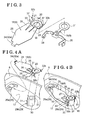
- Figs. 4A and 4B are perspective views each illustrating a method for assembling the lock detection electrode
- Fig. 5 is a cross-sectional view illustrating an assembly state of the lock detection electrode
- Fig. 6 is a cross-sectional view taken along the line VI-VI in Fig. 1 ;
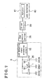
- Fig. 7 is a block diagram of a locking system operated on a basis of a detection result of a lock command detection sensor.
- a door handle device for a vehicle when being applied to a locking system (i.e., a smart entry system) will be explained with reference to the attached drawings.
- a door handle device for a vehicle (hereinafter simply referred to as a door handle device) A includes a door handle 2 supported by a door panel 1 so as to be rotatable in an outward direction of a door for the vehicle (i.e., the door panel 1), and an auxiliary lock 3 brought in a locked state or an unlocked state by a key plate.
- the door handle 2 is arranged in such a manner that a longitudinal direction thereof corresponds to a longitudinal direction of the vehicle.
- the auxiliary lock 3 is arranged at the rear of the door handle 2.
- the door handle 2 includes a first handle case 4 made of resin, a second handle case 5 made of resin, a lock command detection sensor 6 detecting a lock command based on a capacitance, an unlock command detection sensor 7 detecting an unlock command based on a capacitance, and an antenna 8 communicating with a portable device carried by a driver of the vehicle, for example.
- the first handle case 4 is arranged so as to have a void 9 relative to the door panel 1.
- a grip portion 2a is formed at the first handle case 4 so as to face the void 9.
- the second handle case 5 is fixed to the first handle case 4 via screws 10a, 10b, and 10c screwed from a side where the first handle case 4 is provided.
- the second handle case 5 is positioned at an opposite side from the door panel 1 relative to the first handle case 4.
- a rotating support portion 12 is integrally formed at a front portion of the second handle case 5 in the longitudinal direction of the vehicle. Specifically, the rotating support portion 12 is positioned at an inner side of the door panel 1 so as to be rotatably supported by a support member 11 fixed to the inner side of the door panel 1.
- an operating portion 14 is integrally formed at a rear portion of the second handle case 5 in the longitudinal direction of the vehicle.
- the operating portion 14 is positioned at the inner side of the door panel 1 so as to operate an opening and closing lever 13 of a door opening and closing mechanism provided at the inner side of the door panel 1 by a rotating operation of the door handle 2.
- the lock command detection sensor 6 includes an IC board 16, a lock detection electrode 18, and a lock detection circuit connecting portion 19 serving as a circuit connection portion.
- the IC board 16 includes a lock detection signal processing circuit 15 (see Fig. 7 ) fixed to an inner side of the first handle case 4.
- the lock detection electrode 18 is assembled on the second handle case 5 in a state to be arranged along an inner surface 17 of the second handle case 5, the inner surface 17 being substantially parallel to a surface (a plate surface) of the door panel 1.
- the lock detection circuit connecting portion 19 is electrically connected to the lock detection signal processing circuit 15 and the lock detection electrode 18.
- the lock detection electrode 18 is electrically connected to the lock detection circuit connecting portion 19 by bringing an electrode connection ring 20 and a circuit connection ring 21 (which will be explained later) to be electrically connected to each other in a state where the second handle case 5 is fixed to the first handle case 4.
- the lock detection circuit connecting portion 19 is electrically connected to the lock detection signal processing circuit 15 beforehand.
- the unlock command detection sensor 7 includes an unlock detection electrode 22 and an unlock detection signal processing circuit.
- the unlock detection electrode 22 is assembled on the first handle case 4 in a state to be arranged along an inner surface of the grip portion 2a formed at the first handle case 4.
- the unlock detection signal processing circuit is electrically connected to the unlock detection electrode 22.
- the unlock detection signal processing circuit is provided at the IC board 16 where the lock detection signal processing circuit 15 is also provided.
- the IC board 16 including the lock detection signal processing circuit 15 and the unlock detection signal processing circuit is mounted at a circuit board 25 fixed to a front portion of the first handle case 4 so as to face the lock detection electrode 18.
- a transmitting and receiving circuit for the antenna 8 is also mounted at the circuit board 25.
- the lock detection electrode 18 is assembled on the front portion of the second handle case 5 in the longitudinal direction.
- the unlock detection electrode 22 and the antenna 8 are assembled on a rear portion of the first handle case 4 in the longitudinal direction relative to the circuit board 25 in a state where the antenna 8 is arranged to overlap the unlock detection electrode 22 at a side facing the second handle case 5.
- the lock detection circuit connecting portion 19 integrally includes a pair of circuit connection terminals 26 electrically connected to the lock detection signal processing circuit 15, and the circuit connection ring 21 electrically connected to the electrode connection ring 20 provided at an end of a pressing portion 27 (which will be explained later) of the lock detection electrode 18.
- the circuit connection terminals 26 are integrally fixed to the circuit board 25 beforehand by resin or the like so as to be electrically connected to the lock detection signal processing circuit 15.
- the unlock detection electrode 22 is also integrally fixed to the circuit board 25 beforehand by resin or the like so as to be electrically connected to the unlock detection signal processing circuit.
- the antenna 8 is integrally fixed to the circuit board 25 beforehand by resin or the like so as to be electrically connected to the transmitting and receiving circuit.
- the lock detection electrode 18 is obtained by a sheet-metal processing performed on a metallic plate made of phosphor bronze or the like.
- the lock detection electrode 18 integrally includes an electrode body 28 having a plate shape and the pressing portion 27 having a band plate shape.
- the electrode body 28 is elastically deformable and is arranged along the inner surface 17 of the second handle case 5 so that a surface (a plate surface) of the electrode body 28 is in contact with the inner surface 17.
- the pressing portion 27 is also elastically deformable so as to press the electrode body 28 towards the inner surface 17 of the second handle case 5.
- the second handle case 5 includes an engagement mechanism 29 at an inner side so that the lock detection electrode 18 is engageable with the second handle case 5.
- the engagement mechanism 29 includes a first engagement portion 29a engaging with one end (i.e., a first end) of the lock detection electrode 18 in the longitudinal direction of the door handle 2 and a second engagement portion 29b engaging with the other end (i.e., a second end) of the lock detection electrode 18 in the longitudinal direction of the door handle 2.
- the first engagement portion 29a includes an engagement bore formed at the front portion of the second handle case 5 in the longitudinal direction.
- the second engagement portion 29b includes a pair of ribs 31 integrally formed at an outer circumferential portion of a boss 30 while the ribs 31 have an interval therebetween in the circumferential direction of the boss 30.
- the boss 30 is formed at the rear portion of the second handle case 5 in the longitudinal direction relative to the first engagement portion 29a.
- the screw 10b is inserted into the boss 30 so as to fix the second handle case 5 with the first handle case 4.
- the electrode body 28 includes a first hook portion 32a (fitting portion) at the first end so as to be engaged with the first engagement portion 29a.
- the electrode body 28 also includes a contact portion 33 in the rear of the first hook portion 32a in the longitudinal direction so as to be away from the first hook portion 32a.
- the contact portion 33 makes contact with the inner surface 17 of the second handle case 5.
- the first hook portion 32a is formed by a bending of an extending piece 34 that extends from a front end of the electrode body 28.
- the contact portion 33 is formed by end portions of a pair of extending plates 35 extending from a rear end of the electrode body 28 in a band plate shape while an interval is formed between the extending plates 35.
- the pressing portion 27 extends in the band plate shape from a portion between the pair of extending plates 35 of the electrode body 28 so that the pressing portion 27 is integrally connected to a portion between the first hook portion 32a and the contact portion 33 of the electrode body 28.
- the electrode connection ring 20 is integrally formed at an end of the pressing portion 27 so as to be sandwiched and held, together with the circuit connection ring 21, between the boss 30 of the second handle case 5 and the first handle case 4.
- the electrode connection ring 20 and the circuit connection ring 21 (the second handle case 5 and the first handle case 4) are tightened together by the screw 10b.
- the pressing portion 27 includes a bending portion 36 obtained by bending at substantially an intermediate portion of the pressing portion 27 in the longitudinal direction as illustrated in Fig. 5 so that the pressing portion 27 is elastically deformable by a bending deformation of the bending portion 36.
- a second hook portion 32b is formed at an end of the pressing portion 27. Specifically, the second hook portion 32b is provided at the second end of the lock detection electrode 18 so as to engage with the second engagement portion 29b.
- the second hook portion 32b includes two pairs of claws 37 extending from the electrode connection ring 20 as illustrated in Fig. 3 . Then, each of the ribs 31 formed at the boss 30 engages with a portion between each of the pairs of claws 37 as illustrated in Fig. 4B so that the second hook portion 32b is engaged with the second engagement portion 29b.
- a distance between the first hook portion 32a and the second hook portion 32b is defined to be greater than a distance between the first engagement portion 29a and the second engagement portion 29b.
- the extending piece 34 (the first hook portion 32a) is inserted into the engagement bore (the first engagement portion 29a) while the ribs 31 are inserted into the respective portions between the pairs of claws 37 (the second hook portion 32b) as illustrated in Fig. 4B .
- the lock detection electrode 18 is elastically deformed so that the surface of the electrode body 28 is in contact with the inner surface 17 of the second handle case 5 as illustrated in Fig. 5 , thereby engaging the lock detection electrode 18 between the first engagement portion 29a and the second engagement portion 29b.
- Fig. 7 is a block diagram of the locking system operated on a basis of a detection result of the lock command detection sensor 6.
- a capacitance (an electrostatic capacity) C1 obtained between the lock detection electrode 18 and the door panel 1 that functions as an earth GND1 and a capacitance (an electrostatic capacity) C2 between the lock detection electrode 18 and the circuit board 25 at which an earth electrode is provided so as to function as an earth GNDB are formed in parallel to each other.
- a value indicating a combined capacitance that consists of the capacitance C1 and the capacitance C2 is input to the lock detection signal processing circuit 15.
- the capacitance C2 formed between the lock detection electrode 18 and the circuit board 25 is greater than the capacitance C1 formed between the lock detection electrode 18 and the door panel 1.
- a door control portion 38 determines that the door lock command is issued by the user of the vehicle. Therefore, the door control portion 38 drives an actuator (a lock actuator) 41 provided at a lock mechanism 40 via a driver circuit 39 to thereby lock the vehicle door.
- the lock command detection sensor 6 may be assembled on a rotatable end portion (i.e., a rear portion) of the door handle 2.
- lock detection electrode 18 may be assembled on a position away from the circuit board 25, where the lock detection signal processing circuit 15 is provided, in the longitudinal direction of the door handle 2.
- the door handle device A may include the lock detection electrode 18 that is provided at a portion other than a fixing portion between the first handle case 4 and the second handle case 5 and that is electrically connected to the lock detection circuit connecting portion 19 in a state where the second handle case 5 is fixed to the first handle case 4.
- the lock detection electrode 18 may be assembled on a portion of the inner surface of the second handle case 5 facing upward or downward when the door handle device A is mounted to the vehicle.
Landscapes
- Lock And Its Accessories (AREA)
Abstract
Description
- This disclosure generally relates to a door handle device for a vehicle.
- A known door handle device is applicable to a locking system (i.e., a smart entry system) in which a communication is made between a portable device carried by a driver of the vehicle and a main body provided at the vehicle so as to authenticate the portable device. In a case where the authentication is successful, a door of the vehicle is automatically locked and unlocked accordingly. According to a known door handle device for a vehicle such as disclosed in
JP4079646B2 - Thus, in a case where a shape and/or dimensions of the second handle case is changed, for example, the lock detection electrode may not be assembled so as to be arranged along a predetermined portion at the inner surface of the second handle case when the second handle case is fixed to the first handle case. In such case, in order to assemble the lock detection electrode to be arranged along the predetermined portion at the inner surface of the second handle case, dimensions of the circuit connection portion may be changed to thereby fix the lock detection signal processing circuit, to which the circuit connection portion is electrically connected and fixed beforehand, to the inner side of the first handle case, or a shape and/or dimensions of the first handle case may be changed, for example. Accordingly, in a case of aiming to avoid an increase of a manufacturing cost without changes of the dimensions of the circuit connection portion or the shape and/or dimensions of the first handle case when changing the shape and/or dimensions of the second handle case, a flexibility of changing the shape and/or dimensions of the second handle case may decrease.
- A need thus exists for a door handle device for a vehicle in which a flexibility of changing a shape and/or dimensions of a second handle case is improved while restraining an increase of a manufacturing cost of the door handle device.
- According to an aspect of this disclosure, a door handle device for a vehicle includes a door handle configured to be supported by a door panel and being rotatable in an outward direction of the door panel, the door handle including a first handle case arranged to have a void relative to the door panel, a second handle case fixed to the first handle case at a side opposite from the door panel, and a lock command detection sensor detecting a lock command based on a capacitance, the lock command detection sensor including a lock detection signal processing circuit fixed to an inner side of the first handle case, a circuit connection portion electrically connected to the lock detection signal processing circuit, and a lock detection electrode assembled on the second handle case in a state to be arranged along an inner surface of the second handle case, the lock detection electrode being electrically connected to the circuit connection portion in a state where the second handle case is fixed to the first handle case.
- The lock detection electrode and the circuit connection portion are electrically connected to each other in a state where the second handle case is fixed to the first handle case. Thus, the circuit connection portion is provided at the first handle case while the lock detection electrode is provided at the second handle case instead of the first handle case. Specifically, the lock detection electrode is assembled so as to be arranged along a predetermined portion at the inner surface of the second handle case while the lock detection signal processing circuit to which the circuit connection portion is electrically connected and fixed is fixed to the inner side of the first handle case. Therefore, even when a shape and/or dimensions of the second handle case is changed, for example, the lock detection electrode and the circuit connection portion are electrically connected to each other in a state where the second handle case is fixed to the first handle case, without necessary changes of dimensions of the circuit connection portion or a shape and/or dimensions of the first handle case. As a result, a flexibility of the change of the shape and/or dimensions of the second handle case is enhanced while an increase of a manufacturing cost of the door handle device is being restrained.
- The door handle device further includes an engagement mechanism engaging the lock detection electrode relative to the second handle case.
- Accordingly, in a case of fixing the second handle case to the first handle case, the lock detection electrode is brought to engage with the second handle case so as not to remove or disengage from the second handle case. As a result, the second handle case may be easily fixed to the first handle case.
- The engagement mechanism includes a first engagement portion engageable with a first end of the lock detection electrode in a longitudinal direction of the door handle and a second engagement portion engageable with a second end of the lock detection electrode in the longitudinal direction of the door handle, and wherein the lock detection electrode is engaged between the first engagement portion and the second engagement portion while being elastically deformed.
- Accordingly, the lock detection electrode is securely engaged between the first engagement portion and the second engagement portion by means of an elastic restoring force of the lock detection electrode.
- The lock detection electrode includes an electrode body having a plate shape and being elastically deformable, the electrode body including a fitting portion with which one of the first engagement portion and the second engagement portion engages and a contact portion making contact with the inner surface of the second handle case at a position away from the fitting portion in the longitudinal direction, and the lock detection electrode further includes a pressing portion integrally connected to a portion between the fitting portion and the contact portion of the electrode body, the other of the first engagement portion and the second engagement portion engaging with the pressing portion, the pressing portion being elastically deformable to press the electrode body towards the inner surface of the second handle case.
- Accordingly, the fitting portion of the electrode body is engaged with one of the first engagement portion and the second engagement portion while the pressing portion integrally connected to the portion between the fitting portion and the contact portion of the electrode body is engaged with the other of the first engagement portion and the second engagement portion. The pressing portion is elastically deformed so as to press the electrode body to the inner surface of the second handle case. As a result, the plate-shaped electrode body of which the contact portion is in contact with the inner surface of the second handle case at a position away from the fitting portion in the longitudinal direction is elastically deformed towards the inner surface of the second handle case so as to be assembled and arranged along the inner surface of the second handle case. The electrode body may be easily assembled so as to be arranged along the inner surface of the second handle case accordingly.
- A circuit board where the lock detection signal processing circuit is provided is fixed to the first handle case to face the lock detection electrode.
- According to the door handle device where the lock command detection sensor detecting a lock command based on changes in capacity is provided at the door handle, a capacitance formed between the lock detection electrode provided at the door handle and the door panel varies when the door handle rotates relative to the door panel. Thus, the lock command detection sensor may wrongly detect the lock command based on a rotating operation of the door handle. According to the disclosure, a capacitance is formed between the lock detection electrode and the circuit board on a basis of an earth GND that is defined by an earth electrode provided at the circuit board so as to be arranged in parallel to the capacitance formed between the lock detection electrode and the door panel. Because a distance between the lock detection electrode and the circuit board is smaller than a distance between the lock detection electrode and the door panel, the capacitance formed between the lock detection electrode and the circuit board is greater than the capacitance formed between the lock detection electrode and the door panel. As a result, the lock command detection sensor detects whether or not the lock command is issued on a basis of changes in the combined capacitance where the large capacitance formed between the lock detection electrode and the circuit board is added to the capacitance formed between the lock detection electrode and the door panel. Accordingly, changes in capacitance caused by the rotating operation of the door handle decreases, thereby inhibiting the lock command detection sensor from wrongly detecting the lock command on a basis of the rotating operation of the door handle.
- The foregoing and additional features and characteristics of this disclosure will become more apparent from the following detailed description considered with the reference to the accompanying drawings, wherein:
-
Fig. 1 is a horizontal cross-sectional view of a door for a vehicle where a door handle device for a vehicle according to an embodiment is mounted; -
Fig. 2 is an exploded perspective view of the door handle device; -
Fig. 3 is an exploded perspective view of a lock detection electrode and a lock detection circuit contact portion of the door handle device; -
Figs. 4A and 4B are perspective views each illustrating a method for assembling the lock detection electrode; -
Fig. 5 is a cross-sectional view illustrating an assembly state of the lock detection electrode; -
Fig. 6 is a cross-sectional view taken along the line VI-VI inFig. 1 ; and -
Fig. 7 is a block diagram of a locking system operated on a basis of a detection result of a lock command detection sensor. - A door handle device for a vehicle according to an embodiment when being applied to a locking system (i.e., a smart entry system) will be explained with reference to the attached drawings. In the embodiment, directions and orientations such as left, right, front, rear, top, and bottom correspond to those of the vehicle where the door handle device is mounted. As illustrated in
Figs. 1 and2 , a door handle device for a vehicle (hereinafter simply referred to as a door handle device) A includes adoor handle 2 supported by adoor panel 1 so as to be rotatable in an outward direction of a door for the vehicle (i.e., the door panel 1), and anauxiliary lock 3 brought in a locked state or an unlocked state by a key plate. Thedoor handle 2 is arranged in such a manner that a longitudinal direction thereof corresponds to a longitudinal direction of the vehicle. Theauxiliary lock 3 is arranged at the rear of thedoor handle 2. - The
door handle 2 includes afirst handle case 4 made of resin, asecond handle case 5 made of resin, a lockcommand detection sensor 6 detecting a lock command based on a capacitance, an unlockcommand detection sensor 7 detecting an unlock command based on a capacitance, and anantenna 8 communicating with a portable device carried by a driver of the vehicle, for example. - The
first handle case 4 is arranged so as to have avoid 9 relative to thedoor panel 1. Agrip portion 2a is formed at thefirst handle case 4 so as to face thevoid 9. Thesecond handle case 5 is fixed to thefirst handle case 4 viascrews first handle case 4 is provided. Thesecond handle case 5 is positioned at an opposite side from thedoor panel 1 relative to thefirst handle case 4. - In order to support the
door handle 2 so as to be rotatable relative to thedoor panel 1, arotating support portion 12 is integrally formed at a front portion of thesecond handle case 5 in the longitudinal direction of the vehicle. Specifically, therotating support portion 12 is positioned at an inner side of thedoor panel 1 so as to be rotatably supported by asupport member 11 fixed to the inner side of thedoor panel 1. - In addition, an
operating portion 14 is integrally formed at a rear portion of thesecond handle case 5 in the longitudinal direction of the vehicle. Theoperating portion 14 is positioned at the inner side of thedoor panel 1 so as to operate an opening and closinglever 13 of a door opening and closing mechanism provided at the inner side of thedoor panel 1 by a rotating operation of thedoor handle 2. - The lock
command detection sensor 6 includes anIC board 16, alock detection electrode 18, and a lock detectioncircuit connecting portion 19 serving as a circuit connection portion. TheIC board 16 includes a lock detection signal processing circuit 15 (seeFig. 7 ) fixed to an inner side of thefirst handle case 4. Thelock detection electrode 18 is assembled on thesecond handle case 5 in a state to be arranged along aninner surface 17 of thesecond handle case 5, theinner surface 17 being substantially parallel to a surface (a plate surface) of thedoor panel 1. The lock detectioncircuit connecting portion 19 is electrically connected to the lock detectionsignal processing circuit 15 and thelock detection electrode 18. - Specifically, the
lock detection electrode 18 is electrically connected to the lock detectioncircuit connecting portion 19 by bringing anelectrode connection ring 20 and a circuit connection ring 21 (which will be explained later) to be electrically connected to each other in a state where thesecond handle case 5 is fixed to thefirst handle case 4. The lock detectioncircuit connecting portion 19 is electrically connected to the lock detectionsignal processing circuit 15 beforehand. - The unlock
command detection sensor 7 includes anunlock detection electrode 22 and an unlock detection signal processing circuit. Theunlock detection electrode 22 is assembled on thefirst handle case 4 in a state to be arranged along an inner surface of thegrip portion 2a formed at thefirst handle case 4. The unlock detection signal processing circuit is electrically connected to theunlock detection electrode 22. The unlock detection signal processing circuit is provided at theIC board 16 where the lock detectionsignal processing circuit 15 is also provided. - The
IC board 16 including the lock detectionsignal processing circuit 15 and the unlock detection signal processing circuit is mounted at acircuit board 25 fixed to a front portion of thefirst handle case 4 so as to face thelock detection electrode 18. In addition, a transmitting and receiving circuit for theantenna 8 is also mounted at thecircuit board 25. - The
lock detection electrode 18 is assembled on the front portion of thesecond handle case 5 in the longitudinal direction. Theunlock detection electrode 22 and theantenna 8 are assembled on a rear portion of thefirst handle case 4 in the longitudinal direction relative to thecircuit board 25 in a state where theantenna 8 is arranged to overlap theunlock detection electrode 22 at a side facing thesecond handle case 5. - As illustrated in
Fig. 3 , the lock detectioncircuit connecting portion 19 integrally includes a pair ofcircuit connection terminals 26 electrically connected to the lock detectionsignal processing circuit 15, and thecircuit connection ring 21 electrically connected to theelectrode connection ring 20 provided at an end of a pressing portion 27 (which will be explained later) of thelock detection electrode 18. - The
circuit connection terminals 26 are integrally fixed to thecircuit board 25 beforehand by resin or the like so as to be electrically connected to the lock detectionsignal processing circuit 15. Theunlock detection electrode 22 is also integrally fixed to thecircuit board 25 beforehand by resin or the like so as to be electrically connected to the unlock detection signal processing circuit. Further, theantenna 8 is integrally fixed to thecircuit board 25 beforehand by resin or the like so as to be electrically connected to the transmitting and receiving circuit. - As illustrated in
Fig. 3 , thelock detection electrode 18 is obtained by a sheet-metal processing performed on a metallic plate made of phosphor bronze or the like. Thelock detection electrode 18 integrally includes anelectrode body 28 having a plate shape and thepressing portion 27 having a band plate shape. Theelectrode body 28 is elastically deformable and is arranged along theinner surface 17 of thesecond handle case 5 so that a surface (a plate surface) of theelectrode body 28 is in contact with theinner surface 17. Thepressing portion 27 is also elastically deformable so as to press theelectrode body 28 towards theinner surface 17 of thesecond handle case 5. - As illustrated in
Figs. 4A and 4B , thesecond handle case 5 includes anengagement mechanism 29 at an inner side so that thelock detection electrode 18 is engageable with thesecond handle case 5. Theengagement mechanism 29 includes afirst engagement portion 29a engaging with one end (i.e., a first end) of thelock detection electrode 18 in the longitudinal direction of thedoor handle 2 and asecond engagement portion 29b engaging with the other end (i.e., a second end) of thelock detection electrode 18 in the longitudinal direction of thedoor handle 2. - The
first engagement portion 29a includes an engagement bore formed at the front portion of thesecond handle case 5 in the longitudinal direction. Thesecond engagement portion 29b includes a pair ofribs 31 integrally formed at an outer circumferential portion of aboss 30 while theribs 31 have an interval therebetween in the circumferential direction of theboss 30. Theboss 30 is formed at the rear portion of thesecond handle case 5 in the longitudinal direction relative to thefirst engagement portion 29a. Thescrew 10b is inserted into theboss 30 so as to fix thesecond handle case 5 with thefirst handle case 4. - As illustrated in
Fig. 3 , theelectrode body 28 includes afirst hook portion 32a (fitting portion) at the first end so as to be engaged with thefirst engagement portion 29a. Theelectrode body 28 also includes acontact portion 33 in the rear of thefirst hook portion 32a in the longitudinal direction so as to be away from thefirst hook portion 32a. Thecontact portion 33 makes contact with theinner surface 17 of thesecond handle case 5. - The
first hook portion 32a is formed by a bending of an extendingpiece 34 that extends from a front end of theelectrode body 28. Thecontact portion 33 is formed by end portions of a pair of extendingplates 35 extending from a rear end of theelectrode body 28 in a band plate shape while an interval is formed between the extendingplates 35. - As illustrated in
Fig. 3 , thepressing portion 27 extends in the band plate shape from a portion between the pair of extendingplates 35 of theelectrode body 28 so that thepressing portion 27 is integrally connected to a portion between thefirst hook portion 32a and thecontact portion 33 of theelectrode body 28. Theelectrode connection ring 20 is integrally formed at an end of thepressing portion 27 so as to be sandwiched and held, together with thecircuit connection ring 21, between theboss 30 of thesecond handle case 5 and thefirst handle case 4. Theelectrode connection ring 20 and the circuit connection ring 21 (thesecond handle case 5 and the first handle case 4) are tightened together by thescrew 10b. - The
pressing portion 27 includes a bendingportion 36 obtained by bending at substantially an intermediate portion of thepressing portion 27 in the longitudinal direction as illustrated inFig. 5 so that thepressing portion 27 is elastically deformable by a bending deformation of the bendingportion 36. Asecond hook portion 32b is formed at an end of thepressing portion 27. Specifically, thesecond hook portion 32b is provided at the second end of thelock detection electrode 18 so as to engage with thesecond engagement portion 29b. - The
second hook portion 32b includes two pairs ofclaws 37 extending from theelectrode connection ring 20 as illustrated inFig. 3 . Then, each of theribs 31 formed at theboss 30 engages with a portion between each of the pairs ofclaws 37 as illustrated inFig. 4B so that thesecond hook portion 32b is engaged with thesecond engagement portion 29b. - A distance between the
first hook portion 32a and thesecond hook portion 32b is defined to be greater than a distance between thefirst engagement portion 29a and thesecond engagement portion 29b. The extending piece 34 (thefirst hook portion 32a) is inserted into the engagement bore (thefirst engagement portion 29a) while theribs 31 are inserted into the respective portions between the pairs of claws 37 (thesecond hook portion 32b) as illustrated inFig. 4B . Then, thelock detection electrode 18 is elastically deformed so that the surface of theelectrode body 28 is in contact with theinner surface 17 of thesecond handle case 5 as illustrated inFig. 5 , thereby engaging thelock detection electrode 18 between thefirst engagement portion 29a and thesecond engagement portion 29b. -
Fig. 7 is a block diagram of the locking system operated on a basis of a detection result of the lockcommand detection sensor 6. As illustrated inFig. 6 , a capacitance (an electrostatic capacity) C1 obtained between thelock detection electrode 18 and thedoor panel 1 that functions as an earth GND1 and a capacitance (an electrostatic capacity) C2 between thelock detection electrode 18 and thecircuit board 25 at which an earth electrode is provided so as to function as an earth GNDB are formed in parallel to each other. A value indicating a combined capacitance that consists of the capacitance C1 and the capacitance C2 is input to the lock detectionsignal processing circuit 15. - Because a distance between the
lock detection electrode 18 and thecircuit board 25 is smaller than a distance between thelock detection electrode 18 and thedoor panel 1, the capacitance C2 formed between thelock detection electrode 18 and thecircuit board 25 is greater than the capacitance C1 formed between thelock detection electrode 18 and thedoor panel 1. - In the aforementioned state, when a user of the vehicle such as a driver touches a mark M (see
Fig. 2 ) or a vicinity thereof by one's hand, the mark M being provided at a portion of thesecond handle case 5 so as to face thelock detection electrode 18, a capacitance (an electrostatic capacity) C3 is newly obtained between the user of the vehicle functioning as an earth GND2 and thelock detection electrode 18 so as to be parallel to the capacitance C1 and the capacitance C2. Then, a value indicating the combined capacitance that consists of the capacitance C1, the capacitance C2 and the capacitance C3 is input to the lock detectionsignal processing circuit 15. - When the value indicating the combined capacitance obtained by the capacitance C1, the capacitance C2, and the capacitance C3 is input to the lock detection
signal processing circuit 15, adoor control portion 38 determines that the door lock command is issued by the user of the vehicle. Therefore, thedoor control portion 38 drives an actuator (a lock actuator) 41 provided at alock mechanism 40 via adriver circuit 39 to thereby lock the vehicle door. - According to the aforementioned embodiment, the lock
command detection sensor 6 may be assembled on a rotatable end portion (i.e., a rear portion) of thedoor handle 2. - In addition, the
lock detection electrode 18 may be assembled on a position away from thecircuit board 25, where the lock detectionsignal processing circuit 15 is provided, in the longitudinal direction of thedoor handle 2. - Further, the door handle device A may include the
lock detection electrode 18 that is provided at a portion other than a fixing portion between thefirst handle case 4 and thesecond handle case 5 and that is electrically connected to the lock detectioncircuit connecting portion 19 in a state where thesecond handle case 5 is fixed to thefirst handle case 4. - Furthermore, the
lock detection electrode 18 may be assembled on a portion of the inner surface of thesecond handle case 5 facing upward or downward when the door handle device A is mounted to the vehicle.
Claims (5)
- A door handle device for a vehicle (A), comprising:a door handle (2) configured to be supported by a door panel (1) and being rotatable in an outward direction of the door panel (1), the door handle (2) including a first handle case (4) arranged to have a void (9) relative to the door panel (1), a second handle case (5) fixed to the first handle case (4) at a side opposite from the door panel (1), and a lock command detection sensor (6) detecting a lock command based on a capacitance;the lock command detection sensor (6) including a lock detection signal processing circuit (15) fixed to an inner side of the first handle case (4), a circuit connection portion (19) electrically connected to the lock detection signal processing circuit (15), and a lock detection electrode (18) assembled on the second handle case (5) in a state to be arranged along an inner surface (17) of the second handle case (5), the lock detection electrode (18) being electrically connected to the circuit connection portion (19) in a state where the second handle case (5) is fixed to the first handle case (4).
- The door handle device (A) according to claim 1, further comprising an engagement mechanism (29) engaging the lock detection electrode (18) relative to the second handle case (5).
- The door handle device (A) according to claim 2, wherein the engagement mechanism (29) includes a first engagement portion (29a) engageable with a first end of the lock detection electrode (18) in a longitudinal direction of the door handle (2) and a second engagement portion (29b) engageable with a second end of the lock detection electrode (18) in the longitudinal direction of the door handle (2), and wherein the lock detection electrode (18) is engaged between the first engagement portion (29a) and the second engagement portion (29a) while being elastically deformed.
- The door handle device (A) according to claim 3, wherein the lock detection electrode (18) includes an electrode body (28) having a plate shape and being elastically deformable, the electrode body (28) including a fitting portion (32a) with which one of the first engagement portion (29a) and the second engagement portion (29b) engages and a contact portion (33) making contact with the inner surface (17) of the second handle case (5) at a position away from the fitting portion (32a) in the longitudinal direction, and the lock detection electrode (18) further includes a pressing portion (27) integrally connected to a portion between the fitting portion (32a) and the contact portion (33) of the electrode body (28), the other of the first engagement portion (29a) and the second engagement portion (29b) engaging with the pressing portion (27), the pressing portion (27) being elastically deformable to press the electrode body (28) towards the inner surface (17) of the second handle case (5).
- The door handle device (A) according to any one of claims 1 to 4, wherein a circuit board (25) where the lock detection signal processing circuit (15) is provided is fixed to the first handle case (4) to face the lock detection electrode (18).
Applications Claiming Priority (1)
| Application Number | Priority Date | Filing Date | Title |
|---|---|---|---|
| JP2010167428A JP5022483B2 (en) | 2010-07-26 | 2010-07-26 | Vehicle door handle device |
Publications (3)
| Publication Number | Publication Date |
|---|---|
| EP2412897A2 true EP2412897A2 (en) | 2012-02-01 |
| EP2412897A3 EP2412897A3 (en) | 2012-10-31 |
| EP2412897B1 EP2412897B1 (en) | 2015-11-04 |
Family
ID=44993996
Family Applications (1)
| Application Number | Title | Priority Date | Filing Date |
|---|---|---|---|
| EP11175286.1A Active EP2412897B1 (en) | 2010-07-26 | 2011-07-26 | Door handle device for vehicle |
Country Status (4)
| Country | Link |
|---|---|
| US (1) | US9033379B2 (en) |
| EP (1) | EP2412897B1 (en) |
| JP (1) | JP5022483B2 (en) |
| CN (1) | CN102343884B (en) |
Cited By (3)
| Publication number | Priority date | Publication date | Assignee | Title |
|---|---|---|---|---|
| US20120133159A1 (en) * | 2010-11-26 | 2012-05-31 | Aisin Seiki Kabushiki Kaisha | Door handle apparatus |
| WO2018041442A1 (en) * | 2016-08-31 | 2018-03-08 | Huf Hülsbeck & Fürst Gmbh & Co. Kg | Electronics module for a motor vehicle door handle assembly |
| WO2019121090A1 (en) * | 2017-12-21 | 2019-06-27 | Huf Hülsbeck & Fürst Gmbh & Co. Kg | Vehicle door handle |
Families Citing this family (22)
| Publication number | Priority date | Publication date | Assignee | Title |
|---|---|---|---|---|
| AU2013200882B2 (en) * | 2012-02-14 | 2015-03-12 | Allegion (Australia) Pty Ltd | A door or window handle |
| US8701353B2 (en) | 2012-06-29 | 2014-04-22 | Ford Global Technologies, Llc | Deployable door handle for vehicles |
| US9957737B2 (en) | 2012-06-29 | 2018-05-01 | Ford Global Technologies, Llc | Flush-mounted door handle for vehicles |
| JP6064806B2 (en) * | 2013-06-21 | 2017-01-25 | アイシン精機株式会社 | Vehicle door handle |
| JP6388121B2 (en) * | 2014-09-30 | 2018-09-12 | アイシン精機株式会社 | Vehicle door handle device |
| JP6585907B2 (en) * | 2015-03-17 | 2019-10-02 | ローム株式会社 | Electrostatic switch controller and control method therefor, door opening and closing device, and electronic key system |
| US11286694B2 (en) * | 2015-07-13 | 2022-03-29 | Huf Hülsbeck & Fürst Gmbh & Co. Kg | Exterior door handle for a vehicle |
| US11280119B2 (en) | 2015-07-31 | 2022-03-22 | Rohm Co., Ltd. | Contact sensing device, proximity/contact sensing device, door handle device and control method of the door handle device, and electronic key system |
| JP6280898B2 (en) * | 2015-08-26 | 2018-02-14 | 株式会社東海理化電機製作所 | Antenna device |
| CN105239831B (en) * | 2015-10-30 | 2017-08-25 | 杭州六孚智能科技有限公司 | The push-pull mechanism of lockset |
| JP6304209B2 (en) | 2015-11-30 | 2018-04-04 | アイシン精機株式会社 | Vehicle handle device |
| DE102016219748A1 (en) * | 2016-10-11 | 2018-04-12 | Zf Friedrichshafen Ag | Sensor device for a door handle for a vehicle, door handle and method for producing a sensor device |
| US10385594B2 (en) * | 2017-03-06 | 2019-08-20 | Trimark Corporation | Power locking door handle with capacitive sensing |
| FR3067377B1 (en) | 2017-06-13 | 2022-04-15 | Continental Automotive France | DEVICE FOR DETECTING INTENT TO LOCK AND UNLOCK A MOTOR VEHICLE DOOR BY A USER AND DOOR HANDLE COMPRISING SUCH A DEVICE |
| DE102017008340A1 (en) * | 2017-09-05 | 2019-03-07 | Huf Hülsbeck & Fürst Gmbh & Co. Kg | Motor vehicle door handle assembly with embedded electronics |
| WO2019181238A1 (en) * | 2018-03-23 | 2019-09-26 | アルプスアルパイン株式会社 | Door handle |
| FR3081489B1 (en) * | 2018-05-25 | 2022-09-09 | U Shin Italia Spa | OPENING HANDLE DEVICE, IN PARTICULAR FOR VEHICLES |
| JP6410984B1 (en) * | 2018-07-06 | 2018-10-24 | サカエ理研工業株式会社 | Vehicle door handle |
| JP2020066318A (en) * | 2018-10-24 | 2020-04-30 | 本田技研工業株式会社 | Car door structure |
| JP2020126764A (en) * | 2019-02-05 | 2020-08-20 | ホシデン株式会社 | Proximity sensor and door handle device including the same |
| JP7207191B2 (en) * | 2019-06-19 | 2023-01-18 | 株式会社アイシン | VEHICLE DOOR HANDLE DEVICE AND METHOD OF FIXING ELECTRONIC CIRCUIT DEVICE FOR VEHICLE DOOR HANDLE DEVICE |
| US12546150B2 (en) * | 2021-01-07 | 2026-02-10 | Ford Global Technologies, Llc | Door assembly for motor vehicle |
Citations (1)
| Publication number | Priority date | Publication date | Assignee | Title |
|---|---|---|---|---|
| JPH0479646B2 (en) | 1984-03-22 | 1992-12-16 | Sanyo Electric Co |
Family Cites Families (21)
| Publication number | Priority date | Publication date | Assignee | Title |
|---|---|---|---|---|
| DE10015887C1 (en) * | 2000-03-30 | 2002-01-17 | Huf Huelsbeck & Fuerst Gmbh | Access system for a vehicle |
| JP3502848B2 (en) | 2001-03-28 | 2004-03-02 | 株式会社ホンダロック | Device for confirming vehicle door opening / locking |
| JP4079646B2 (en) | 2002-01-30 | 2008-04-23 | 株式会社アルファ | Vehicle door outside handle device |
| JP3770218B2 (en) * | 2002-08-29 | 2006-04-26 | アイシン精機株式会社 | Human body detection device for vehicle door opening and method of using the same |
| GB2421799B (en) * | 2003-06-20 | 2006-11-15 | Honda Lock Kk | Vehicle door outer handle system |
| JP4240307B2 (en) * | 2004-06-22 | 2009-03-18 | アイシン精機株式会社 | Vehicle door opening and closing device |
| JP4650694B2 (en) * | 2004-06-23 | 2011-03-16 | アイシン精機株式会社 | Vehicle handle |
| JP4126664B2 (en) | 2004-08-04 | 2008-07-30 | 日立金属株式会社 | ANTENNA DEVICE AND COMMUNICATION DEVICE USING THE SAME |
| DE102005031441A1 (en) * | 2005-07-04 | 2007-01-11 | Huf Hülsbeck & Fürst Gmbh & Co. Kg | handle device |
| JP2007138565A (en) * | 2005-11-18 | 2007-06-07 | Aisin Seiki Co Ltd | Vehicle door opening and closing device |
| JP4600323B2 (en) * | 2006-03-15 | 2010-12-15 | アイシン精機株式会社 | Vehicle door handle |
| JP4535010B2 (en) | 2006-03-16 | 2010-09-01 | アイシン精機株式会社 | Vehicle door handle |
| DE602007000993D1 (en) * | 2006-03-16 | 2009-06-10 | Aisin Seiki | Door handle device for vehicles |
| JP5183078B2 (en) | 2006-03-30 | 2013-04-17 | 株式会社フジクラ | Human body approach detection device |
| JP4947348B2 (en) * | 2006-09-13 | 2012-06-06 | アイシン精機株式会社 | Vehicle door handle device |
| JP4655230B2 (en) * | 2006-09-20 | 2011-03-23 | アイシン精機株式会社 | Bobbin for bar antenna, bar antenna and vehicle door handle |
| JP4751861B2 (en) * | 2007-07-27 | 2011-08-17 | アイシン精機株式会社 | Door handle device |
| JP4751860B2 (en) | 2007-07-27 | 2011-08-17 | アイシン精機株式会社 | Door handle device |
| JP4938580B2 (en) * | 2007-07-27 | 2012-05-23 | アイシン精機株式会社 | Door handle device |
| JP5131472B2 (en) | 2008-07-24 | 2013-01-30 | アイシン精機株式会社 | Door handle device |
| JP5556620B2 (en) | 2010-11-26 | 2014-07-23 | アイシン精機株式会社 | Door handle device |
-
2010
- 2010-07-26 JP JP2010167428A patent/JP5022483B2/en active Active
-
2011
- 2011-07-20 US US13/186,914 patent/US9033379B2/en active Active
- 2011-07-22 CN CN201110216675.6A patent/CN102343884B/en active Active
- 2011-07-26 EP EP11175286.1A patent/EP2412897B1/en active Active
Patent Citations (1)
| Publication number | Priority date | Publication date | Assignee | Title |
|---|---|---|---|---|
| JPH0479646B2 (en) | 1984-03-22 | 1992-12-16 | Sanyo Electric Co |
Cited By (4)
| Publication number | Priority date | Publication date | Assignee | Title |
|---|---|---|---|---|
| US20120133159A1 (en) * | 2010-11-26 | 2012-05-31 | Aisin Seiki Kabushiki Kaisha | Door handle apparatus |
| WO2018041442A1 (en) * | 2016-08-31 | 2018-03-08 | Huf Hülsbeck & Fürst Gmbh & Co. Kg | Electronics module for a motor vehicle door handle assembly |
| WO2019121090A1 (en) * | 2017-12-21 | 2019-06-27 | Huf Hülsbeck & Fürst Gmbh & Co. Kg | Vehicle door handle |
| CN111406140A (en) * | 2017-12-21 | 2020-07-10 | 霍富许尔斯贝克和富斯特有限及两合公司 | door handle |
Also Published As
| Publication number | Publication date |
|---|---|
| JP5022483B2 (en) | 2012-09-12 |
| EP2412897B1 (en) | 2015-11-04 |
| US9033379B2 (en) | 2015-05-19 |
| US20120019014A1 (en) | 2012-01-26 |
| CN102343884A (en) | 2012-02-08 |
| EP2412897A3 (en) | 2012-10-31 |
| CN102343884B (en) | 2015-09-30 |
| JP2012026205A (en) | 2012-02-09 |
Similar Documents
| Publication | Publication Date | Title |
|---|---|---|
| EP2412897B1 (en) | Door handle device for vehicle | |
| EP2148025B1 (en) | Door handle apparatus | |
| US9745778B1 (en) | Keyless entry handle and compressible spacer therefor | |
| EP3375960B1 (en) | Power locking door handle with capacitive sensing | |
| AU2012367474B2 (en) | Battery holder | |
| KR101090379B1 (en) | Lever Type Digilog Door Lock | |
| KR101939077B1 (en) | Door handle and antenna unit | |
| EP3054070A1 (en) | Opening/closing member opening/closing apparatus | |
| CN103216161A (en) | Latch releasing system for vehicle door | |
| WO2021102117A1 (en) | Sealing of an electronic lock | |
| JP4970143B2 (en) | Door opener | |
| JP2016138845A (en) | Distortion amount detection device and door handlebar using distortion amount detection device | |
| JP5309461B2 (en) | Door opening / closing control device | |
| US20100175974A1 (en) | Low profile multi-directional key unit structure | |
| JP6099426B2 (en) | Door handle device | |
| CN217847185U (en) | Sensor unit of a vehicle locking system, vehicle locking system and vehicle | |
| JP2008057237A (en) | Vehicle door opening and closing device | |
| KR20170050420A (en) | Switch For Opening Or Closing TailGate And Operating Method The Same | |
| CN110738756A (en) | Remote control apparatus for vehicle | |
| KR101090380B1 (en) | Lever Type Digilog Door Lock | |
| JP7434674B1 (en) | door handle | |
| JP4725141B2 (en) | Door handle structure | |
| US20180293828A1 (en) | Handheld transmitter and motor vehicle | |
| JP2012041714A (en) | Portable machine | |
| KR20100023341A (en) | Switch assembly for pic handle |
Legal Events
| Date | Code | Title | Description |
|---|---|---|---|
| AK | Designated contracting states |
Kind code of ref document: A2 Designated state(s): AL AT BE BG CH CY CZ DE DK EE ES FI FR GB GR HR HU IE IS IT LI LT LU LV MC MK MT NL NO PL PT RO RS SE SI SK SM TR |
|
| AX | Request for extension of the european patent |
Extension state: BA ME |
|
| PUAI | Public reference made under article 153(3) epc to a published international application that has entered the european phase |
Free format text: ORIGINAL CODE: 0009012 |
|
| PUAL | Search report despatched |
Free format text: ORIGINAL CODE: 0009013 |
|
| AK | Designated contracting states |
Kind code of ref document: A3 Designated state(s): AL AT BE BG CH CY CZ DE DK EE ES FI FR GB GR HR HU IE IS IT LI LT LU LV MC MK MT NL NO PL PT RO RS SE SI SK SM TR |
|
| AX | Request for extension of the european patent |
Extension state: BA ME |
|
| RIC1 | Information provided on ipc code assigned before grant |
Ipc: E05B 65/20 20060101ALI20120924BHEP Ipc: E05B 1/00 20060101AFI20120924BHEP Ipc: E05B 17/22 20060101ALI20120924BHEP |
|
| RAP1 | Party data changed (applicant data changed or rights of an application transferred) |
Owner name: TOYOTA JIDOSHA KABUSHIKI KAISHA Owner name: AISIN SEIKI KABUSHIKI KAISHA |
|
| 17P | Request for examination filed |
Effective date: 20130430 |
|
| REG | Reference to a national code |
Ref country code: DE Ref legal event code: R079 Ref document number: 602011021102 Country of ref document: DE Free format text: PREVIOUS MAIN CLASS: E05B0001000000 Ipc: E05B0085160000 |
|
| RIC1 | Information provided on ipc code assigned before grant |
Ipc: E05B 85/16 20140101AFI20150226BHEP Ipc: E05B 81/78 20140101ALI20150226BHEP |
|
| GRAP | Despatch of communication of intention to grant a patent |
Free format text: ORIGINAL CODE: EPIDOSNIGR1 |
|
| INTG | Intention to grant announced |
Effective date: 20150529 |
|
| RIN1 | Information on inventor provided before grant (corrected) |
Inventor name: NISHIYAMA, SHIGEKI Inventor name: OKADA, HIROKI Inventor name: MUSHIAKE, EIJI Inventor name: TATEISHI, MASASHI Inventor name: ATSUMI, RYUTA |
|
| GRAS | Grant fee paid |
Free format text: ORIGINAL CODE: EPIDOSNIGR3 |
|
| GRAR | Information related to intention to grant a patent recorded |
Free format text: ORIGINAL CODE: EPIDOSNIGR71 |
|
| GRAA | (expected) grant |
Free format text: ORIGINAL CODE: 0009210 |
|
| AK | Designated contracting states |
Kind code of ref document: B1 Designated state(s): AL AT BE BG CH CY CZ DE DK EE ES FI FR GB GR HR HU IE IS IT LI LT LU LV MC MK MT NL NO PL PT RO RS SE SI SK SM TR |
|
| INTG | Intention to grant announced |
Effective date: 20150928 |
|
| REG | Reference to a national code |
Ref country code: GB Ref legal event code: FG4D |
|
| REG | Reference to a national code |
Ref country code: CH Ref legal event code: EP |
|
| REG | Reference to a national code |
Ref country code: AT Ref legal event code: REF Ref document number: 759319 Country of ref document: AT Kind code of ref document: T Effective date: 20151115 |
|
| REG | Reference to a national code |
Ref country code: IE Ref legal event code: FG4D |
|
| REG | Reference to a national code |
Ref country code: DE Ref legal event code: R096 Ref document number: 602011021102 Country of ref document: DE |
|
| REG | Reference to a national code |
Ref country code: NL Ref legal event code: MP Effective date: 20151104 |
|
| REG | Reference to a national code |
Ref country code: LT Ref legal event code: MG4D |
|
| REG | Reference to a national code |
Ref country code: AT Ref legal event code: MK05 Ref document number: 759319 Country of ref document: AT Kind code of ref document: T Effective date: 20151104 |
|
| PG25 | Lapsed in a contracting state [announced via postgrant information from national office to epo] |
Ref country code: IS Free format text: LAPSE BECAUSE OF FAILURE TO SUBMIT A TRANSLATION OF THE DESCRIPTION OR TO PAY THE FEE WITHIN THE PRESCRIBED TIME-LIMIT Effective date: 20160304 Ref country code: LT Free format text: LAPSE BECAUSE OF FAILURE TO SUBMIT A TRANSLATION OF THE DESCRIPTION OR TO PAY THE FEE WITHIN THE PRESCRIBED TIME-LIMIT Effective date: 20151104 Ref country code: NL Free format text: LAPSE BECAUSE OF FAILURE TO SUBMIT A TRANSLATION OF THE DESCRIPTION OR TO PAY THE FEE WITHIN THE PRESCRIBED TIME-LIMIT Effective date: 20151104 Ref country code: IT Free format text: LAPSE BECAUSE OF FAILURE TO SUBMIT A TRANSLATION OF THE DESCRIPTION OR TO PAY THE FEE WITHIN THE PRESCRIBED TIME-LIMIT Effective date: 20151104 Ref country code: NO Free format text: LAPSE BECAUSE OF FAILURE TO SUBMIT A TRANSLATION OF THE DESCRIPTION OR TO PAY THE FEE WITHIN THE PRESCRIBED TIME-LIMIT Effective date: 20160204 Ref country code: ES Free format text: LAPSE BECAUSE OF FAILURE TO SUBMIT A TRANSLATION OF THE DESCRIPTION OR TO PAY THE FEE WITHIN THE PRESCRIBED TIME-LIMIT Effective date: 20151104 Ref country code: HR Free format text: LAPSE BECAUSE OF FAILURE TO SUBMIT A TRANSLATION OF THE DESCRIPTION OR TO PAY THE FEE WITHIN THE PRESCRIBED TIME-LIMIT Effective date: 20151104 |
|
| PG25 | Lapsed in a contracting state [announced via postgrant information from national office to epo] |
Ref country code: AT Free format text: LAPSE BECAUSE OF FAILURE TO SUBMIT A TRANSLATION OF THE DESCRIPTION OR TO PAY THE FEE WITHIN THE PRESCRIBED TIME-LIMIT Effective date: 20151104 Ref country code: RS Free format text: LAPSE BECAUSE OF FAILURE TO SUBMIT A TRANSLATION OF THE DESCRIPTION OR TO PAY THE FEE WITHIN THE PRESCRIBED TIME-LIMIT Effective date: 20151104 Ref country code: LV Free format text: LAPSE BECAUSE OF FAILURE TO SUBMIT A TRANSLATION OF THE DESCRIPTION OR TO PAY THE FEE WITHIN THE PRESCRIBED TIME-LIMIT Effective date: 20151104 Ref country code: GR Free format text: LAPSE BECAUSE OF FAILURE TO SUBMIT A TRANSLATION OF THE DESCRIPTION OR TO PAY THE FEE WITHIN THE PRESCRIBED TIME-LIMIT Effective date: 20160205 Ref country code: FI Free format text: LAPSE BECAUSE OF FAILURE TO SUBMIT A TRANSLATION OF THE DESCRIPTION OR TO PAY THE FEE WITHIN THE PRESCRIBED TIME-LIMIT Effective date: 20151104 Ref country code: SE Free format text: LAPSE BECAUSE OF FAILURE TO SUBMIT A TRANSLATION OF THE DESCRIPTION OR TO PAY THE FEE WITHIN THE PRESCRIBED TIME-LIMIT Effective date: 20151104 Ref country code: PL Free format text: LAPSE BECAUSE OF FAILURE TO SUBMIT A TRANSLATION OF THE DESCRIPTION OR TO PAY THE FEE WITHIN THE PRESCRIBED TIME-LIMIT Effective date: 20151104 Ref country code: PT Free format text: LAPSE BECAUSE OF FAILURE TO SUBMIT A TRANSLATION OF THE DESCRIPTION OR TO PAY THE FEE WITHIN THE PRESCRIBED TIME-LIMIT Effective date: 20160304 |
|
| REG | Reference to a national code |
Ref country code: FR Ref legal event code: PLFP Year of fee payment: 6 |
|
| PG25 | Lapsed in a contracting state [announced via postgrant information from national office to epo] |
Ref country code: CZ Free format text: LAPSE BECAUSE OF FAILURE TO SUBMIT A TRANSLATION OF THE DESCRIPTION OR TO PAY THE FEE WITHIN THE PRESCRIBED TIME-LIMIT Effective date: 20151104 |
|
| REG | Reference to a national code |
Ref country code: DE Ref legal event code: R097 Ref document number: 602011021102 Country of ref document: DE |
|
| PG25 | Lapsed in a contracting state [announced via postgrant information from national office to epo] |
Ref country code: DK Free format text: LAPSE BECAUSE OF FAILURE TO SUBMIT A TRANSLATION OF THE DESCRIPTION OR TO PAY THE FEE WITHIN THE PRESCRIBED TIME-LIMIT Effective date: 20151104 Ref country code: EE Free format text: LAPSE BECAUSE OF FAILURE TO SUBMIT A TRANSLATION OF THE DESCRIPTION OR TO PAY THE FEE WITHIN THE PRESCRIBED TIME-LIMIT Effective date: 20151104 Ref country code: SK Free format text: LAPSE BECAUSE OF FAILURE TO SUBMIT A TRANSLATION OF THE DESCRIPTION OR TO PAY THE FEE WITHIN THE PRESCRIBED TIME-LIMIT Effective date: 20151104 Ref country code: SM Free format text: LAPSE BECAUSE OF FAILURE TO SUBMIT A TRANSLATION OF THE DESCRIPTION OR TO PAY THE FEE WITHIN THE PRESCRIBED TIME-LIMIT Effective date: 20151104 Ref country code: RO Free format text: LAPSE BECAUSE OF FAILURE TO SUBMIT A TRANSLATION OF THE DESCRIPTION OR TO PAY THE FEE WITHIN THE PRESCRIBED TIME-LIMIT Effective date: 20151104 |
|
| PLBE | No opposition filed within time limit |
Free format text: ORIGINAL CODE: 0009261 |
|
| STAA | Information on the status of an ep patent application or granted ep patent |
Free format text: STATUS: NO OPPOSITION FILED WITHIN TIME LIMIT |
|
| 26N | No opposition filed |
Effective date: 20160805 |
|
| PG25 | Lapsed in a contracting state [announced via postgrant information from national office to epo] |
Ref country code: SI Free format text: LAPSE BECAUSE OF FAILURE TO SUBMIT A TRANSLATION OF THE DESCRIPTION OR TO PAY THE FEE WITHIN THE PRESCRIBED TIME-LIMIT Effective date: 20151104 |
|
| PG25 | Lapsed in a contracting state [announced via postgrant information from national office to epo] |
Ref country code: BE Free format text: LAPSE BECAUSE OF FAILURE TO SUBMIT A TRANSLATION OF THE DESCRIPTION OR TO PAY THE FEE WITHIN THE PRESCRIBED TIME-LIMIT Effective date: 20151104 |
|
| REG | Reference to a national code |
Ref country code: CH Ref legal event code: PL |
|
| GBPC | Gb: european patent ceased through non-payment of renewal fee |
Effective date: 20160726 |
|
| PG25 | Lapsed in a contracting state [announced via postgrant information from national office to epo] |
Ref country code: MC Free format text: LAPSE BECAUSE OF FAILURE TO SUBMIT A TRANSLATION OF THE DESCRIPTION OR TO PAY THE FEE WITHIN THE PRESCRIBED TIME-LIMIT Effective date: 20151104 |
|
| PG25 | Lapsed in a contracting state [announced via postgrant information from national office to epo] |
Ref country code: CH Free format text: LAPSE BECAUSE OF NON-PAYMENT OF DUE FEES Effective date: 20160731 Ref country code: LI Free format text: LAPSE BECAUSE OF NON-PAYMENT OF DUE FEES Effective date: 20160731 |
|
| REG | Reference to a national code |
Ref country code: IE Ref legal event code: MM4A |
|
| PG25 | Lapsed in a contracting state [announced via postgrant information from national office to epo] |
Ref country code: GB Free format text: LAPSE BECAUSE OF NON-PAYMENT OF DUE FEES Effective date: 20160726 |
|
| REG | Reference to a national code |
Ref country code: FR Ref legal event code: PLFP Year of fee payment: 7 |
|
| PG25 | Lapsed in a contracting state [announced via postgrant information from national office to epo] |
Ref country code: IE Free format text: LAPSE BECAUSE OF NON-PAYMENT OF DUE FEES Effective date: 20160726 |
|
| PG25 | Lapsed in a contracting state [announced via postgrant information from national office to epo] |
Ref country code: LU Free format text: LAPSE BECAUSE OF NON-PAYMENT OF DUE FEES Effective date: 20160726 |
|
| REG | Reference to a national code |
Ref country code: DE Ref legal event code: R084 Ref document number: 602011021102 Country of ref document: DE |
|
| PG25 | Lapsed in a contracting state [announced via postgrant information from national office to epo] |
Ref country code: HU Free format text: LAPSE BECAUSE OF FAILURE TO SUBMIT A TRANSLATION OF THE DESCRIPTION OR TO PAY THE FEE WITHIN THE PRESCRIBED TIME-LIMIT; INVALID AB INITIO Effective date: 20110726 Ref country code: CY Free format text: LAPSE BECAUSE OF FAILURE TO SUBMIT A TRANSLATION OF THE DESCRIPTION OR TO PAY THE FEE WITHIN THE PRESCRIBED TIME-LIMIT Effective date: 20151104 |
|
| REG | Reference to a national code |
Ref country code: FR Ref legal event code: PLFP Year of fee payment: 8 |
|
| PG25 | Lapsed in a contracting state [announced via postgrant information from national office to epo] |
Ref country code: MK Free format text: LAPSE BECAUSE OF FAILURE TO SUBMIT A TRANSLATION OF THE DESCRIPTION OR TO PAY THE FEE WITHIN THE PRESCRIBED TIME-LIMIT Effective date: 20151104 Ref country code: TR Free format text: LAPSE BECAUSE OF FAILURE TO SUBMIT A TRANSLATION OF THE DESCRIPTION OR TO PAY THE FEE WITHIN THE PRESCRIBED TIME-LIMIT Effective date: 20151104 Ref country code: MT Free format text: LAPSE BECAUSE OF NON-PAYMENT OF DUE FEES Effective date: 20160731 |
|
| PG25 | Lapsed in a contracting state [announced via postgrant information from national office to epo] |
Ref country code: BG Free format text: LAPSE BECAUSE OF FAILURE TO SUBMIT A TRANSLATION OF THE DESCRIPTION OR TO PAY THE FEE WITHIN THE PRESCRIBED TIME-LIMIT Effective date: 20151104 |
|
| PG25 | Lapsed in a contracting state [announced via postgrant information from national office to epo] |
Ref country code: AL Free format text: LAPSE BECAUSE OF FAILURE TO SUBMIT A TRANSLATION OF THE DESCRIPTION OR TO PAY THE FEE WITHIN THE PRESCRIBED TIME-LIMIT Effective date: 20151104 |
|
| PGFP | Annual fee paid to national office [announced via postgrant information from national office to epo] |
Ref country code: FR Payment date: 20250610 Year of fee payment: 15 |
|
| PGFP | Annual fee paid to national office [announced via postgrant information from national office to epo] |
Ref country code: DE Payment date: 20250604 Year of fee payment: 15 |