EP2412832A1 - Grain-oriented electrical steel sheet and producing method therefor - Google Patents
Grain-oriented electrical steel sheet and producing method therefor Download PDFInfo
- Publication number
- EP2412832A1 EP2412832A1 EP10750519A EP10750519A EP2412832A1 EP 2412832 A1 EP2412832 A1 EP 2412832A1 EP 10750519 A EP10750519 A EP 10750519A EP 10750519 A EP10750519 A EP 10750519A EP 2412832 A1 EP2412832 A1 EP 2412832A1
- Authority
- EP
- European Patent Office
- Prior art keywords
- steel sheet
- grain
- oriented electrical
- electrical steel
- sheet according
- Prior art date
- Legal status (The legal status is an assumption and is not a legal conclusion. Google has not performed a legal analysis and makes no representation as to the accuracy of the status listed.)
- Granted
Links
- 229910001224 Grain-oriented electrical steel Inorganic materials 0.000 title claims abstract description 84
- 238000000034 method Methods 0.000 title claims abstract description 67
- 229910000831 Steel Inorganic materials 0.000 claims abstract description 164
- 239000010959 steel Substances 0.000 claims abstract description 164
- 238000000137 annealing Methods 0.000 claims abstract description 96
- 238000005096 rolling process Methods 0.000 claims abstract description 32
- 239000013078 crystal Substances 0.000 claims description 47
- 238000009751 slip forming Methods 0.000 claims description 5
- 238000010438 heat treatment Methods 0.000 description 17
- 230000000694 effects Effects 0.000 description 16
- 238000010586 diagram Methods 0.000 description 15
- 230000000052 comparative effect Effects 0.000 description 10
- 230000007423 decrease Effects 0.000 description 9
- 238000001953 recrystallisation Methods 0.000 description 9
- 238000004519 manufacturing process Methods 0.000 description 7
- 238000009966 trimming Methods 0.000 description 5
- 238000005299 abrasion Methods 0.000 description 4
- 239000000463 material Substances 0.000 description 4
- 238000007670 refining Methods 0.000 description 4
- 230000015556 catabolic process Effects 0.000 description 3
- 238000007796 conventional method Methods 0.000 description 3
- 238000005261 decarburization Methods 0.000 description 3
- 230000003247 decreasing effect Effects 0.000 description 3
- 238000006731 degradation reaction Methods 0.000 description 3
- 230000003292 diminished effect Effects 0.000 description 3
- 230000006698 induction Effects 0.000 description 3
- 239000004065 semiconductor Substances 0.000 description 3
- 238000002474 experimental method Methods 0.000 description 2
- 230000005415 magnetization Effects 0.000 description 2
- 238000007711 solidification Methods 0.000 description 2
- XLYOFNOQVPJJNP-UHFFFAOYSA-N water Substances O XLYOFNOQVPJJNP-UHFFFAOYSA-N 0.000 description 2
- 238000012935 Averaging Methods 0.000 description 1
- 239000002253 acid Substances 0.000 description 1
- 238000005452 bending Methods 0.000 description 1
- 239000010960 cold rolled steel Substances 0.000 description 1
- 238000005097 cold rolling Methods 0.000 description 1
- 238000002425 crystallisation Methods 0.000 description 1
- 230000008025 crystallization Effects 0.000 description 1
- 238000005520 cutting process Methods 0.000 description 1
- 238000011156 evaluation Methods 0.000 description 1
- 239000000835 fiber Substances 0.000 description 1
- 239000012467 final product Substances 0.000 description 1
- 238000002347 injection Methods 0.000 description 1
- 239000007924 injection Substances 0.000 description 1
- 239000007788 liquid Substances 0.000 description 1
- 239000000203 mixture Substances 0.000 description 1
- 239000000047 product Substances 0.000 description 1
- 238000005482 strain hardening Methods 0.000 description 1
- 239000000126 substance Substances 0.000 description 1
- 230000001629 suppression Effects 0.000 description 1
- 238000004804 winding Methods 0.000 description 1
Images


Classifications
-
- C—CHEMISTRY; METALLURGY
- C21—METALLURGY OF IRON
- C21D—MODIFYING THE PHYSICAL STRUCTURE OF FERROUS METALS; GENERAL DEVICES FOR HEAT TREATMENT OF FERROUS OR NON-FERROUS METALS OR ALLOYS; MAKING METAL MALLEABLE, e.g. BY DECARBURISATION OR TEMPERING
- C21D8/00—Modifying the physical properties by deformation combined with, or followed by, heat treatment
- C21D8/12—Modifying the physical properties by deformation combined with, or followed by, heat treatment during manufacturing of articles with special electromagnetic properties
-
- C—CHEMISTRY; METALLURGY
- C21—METALLURGY OF IRON
- C21D—MODIFYING THE PHYSICAL STRUCTURE OF FERROUS METALS; GENERAL DEVICES FOR HEAT TREATMENT OF FERROUS OR NON-FERROUS METALS OR ALLOYS; MAKING METAL MALLEABLE, e.g. BY DECARBURISATION OR TEMPERING
- C21D1/00—General methods or devices for heat treatment, e.g. annealing, hardening, quenching or tempering
- C21D1/34—Methods of heating
-
- C—CHEMISTRY; METALLURGY
- C21—METALLURGY OF IRON
- C21D—MODIFYING THE PHYSICAL STRUCTURE OF FERROUS METALS; GENERAL DEVICES FOR HEAT TREATMENT OF FERROUS OR NON-FERROUS METALS OR ALLOYS; MAKING METAL MALLEABLE, e.g. BY DECARBURISATION OR TEMPERING
- C21D10/00—Modifying the physical properties by methods other than heat treatment or deformation
- C21D10/005—Modifying the physical properties by methods other than heat treatment or deformation by laser shock processing
-
- C—CHEMISTRY; METALLURGY
- C21—METALLURGY OF IRON
- C21D—MODIFYING THE PHYSICAL STRUCTURE OF FERROUS METALS; GENERAL DEVICES FOR HEAT TREATMENT OF FERROUS OR NON-FERROUS METALS OR ALLOYS; MAKING METAL MALLEABLE, e.g. BY DECARBURISATION OR TEMPERING
- C21D8/00—Modifying the physical properties by deformation combined with, or followed by, heat treatment
- C21D8/12—Modifying the physical properties by deformation combined with, or followed by, heat treatment during manufacturing of articles with special electromagnetic properties
- C21D8/1244—Modifying the physical properties by deformation combined with, or followed by, heat treatment during manufacturing of articles with special electromagnetic properties the heat treatment(s) being of interest
- C21D8/1272—Final recrystallisation annealing
-
- C—CHEMISTRY; METALLURGY
- C21—METALLURGY OF IRON
- C21D—MODIFYING THE PHYSICAL STRUCTURE OF FERROUS METALS; GENERAL DEVICES FOR HEAT TREATMENT OF FERROUS OR NON-FERROUS METALS OR ALLOYS; MAKING METAL MALLEABLE, e.g. BY DECARBURISATION OR TEMPERING
- C21D8/00—Modifying the physical properties by deformation combined with, or followed by, heat treatment
- C21D8/12—Modifying the physical properties by deformation combined with, or followed by, heat treatment during manufacturing of articles with special electromagnetic properties
- C21D8/1294—Modifying the physical properties by deformation combined with, or followed by, heat treatment during manufacturing of articles with special electromagnetic properties involving a localized treatment
-
- C—CHEMISTRY; METALLURGY
- C21—METALLURGY OF IRON
- C21D—MODIFYING THE PHYSICAL STRUCTURE OF FERROUS METALS; GENERAL DEVICES FOR HEAT TREATMENT OF FERROUS OR NON-FERROUS METALS OR ALLOYS; MAKING METAL MALLEABLE, e.g. BY DECARBURISATION OR TEMPERING
- C21D9/00—Heat treatment, e.g. annealing, hardening, quenching or tempering, adapted for particular articles; Furnaces therefor
- C21D9/46—Heat treatment, e.g. annealing, hardening, quenching or tempering, adapted for particular articles; Furnaces therefor for sheet metals
-
- C—CHEMISTRY; METALLURGY
- C21—METALLURGY OF IRON
- C21D—MODIFYING THE PHYSICAL STRUCTURE OF FERROUS METALS; GENERAL DEVICES FOR HEAT TREATMENT OF FERROUS OR NON-FERROUS METALS OR ALLOYS; MAKING METAL MALLEABLE, e.g. BY DECARBURISATION OR TEMPERING
- C21D9/00—Heat treatment, e.g. annealing, hardening, quenching or tempering, adapted for particular articles; Furnaces therefor
- C21D9/52—Heat treatment, e.g. annealing, hardening, quenching or tempering, adapted for particular articles; Furnaces therefor for wires; for strips ; for rods of unlimited length
- C21D9/54—Furnaces for treating strips or wire
- C21D9/663—Bell-type furnaces
-
- H—ELECTRICITY
- H01—ELECTRIC ELEMENTS
- H01F—MAGNETS; INDUCTANCES; TRANSFORMERS; SELECTION OF MATERIALS FOR THEIR MAGNETIC PROPERTIES
- H01F1/00—Magnets or magnetic bodies characterised by the magnetic materials therefor; Selection of materials for their magnetic properties
- H01F1/01—Magnets or magnetic bodies characterised by the magnetic materials therefor; Selection of materials for their magnetic properties of inorganic materials
- H01F1/03—Magnets or magnetic bodies characterised by the magnetic materials therefor; Selection of materials for their magnetic properties of inorganic materials characterised by their coercivity
- H01F1/12—Magnets or magnetic bodies characterised by the magnetic materials therefor; Selection of materials for their magnetic properties of inorganic materials characterised by their coercivity of soft-magnetic materials
- H01F1/14—Magnets or magnetic bodies characterised by the magnetic materials therefor; Selection of materials for their magnetic properties of inorganic materials characterised by their coercivity of soft-magnetic materials metals or alloys
- H01F1/16—Magnets or magnetic bodies characterised by the magnetic materials therefor; Selection of materials for their magnetic properties of inorganic materials characterised by their coercivity of soft-magnetic materials metals or alloys in the form of sheets
-
- C—CHEMISTRY; METALLURGY
- C21—METALLURGY OF IRON
- C21D—MODIFYING THE PHYSICAL STRUCTURE OF FERROUS METALS; GENERAL DEVICES FOR HEAT TREATMENT OF FERROUS OR NON-FERROUS METALS OR ALLOYS; MAKING METAL MALLEABLE, e.g. BY DECARBURISATION OR TEMPERING
- C21D2201/00—Treatment for obtaining particular effects
- C21D2201/05—Grain orientation
-
- Y—GENERAL TAGGING OF NEW TECHNOLOGICAL DEVELOPMENTS; GENERAL TAGGING OF CROSS-SECTIONAL TECHNOLOGIES SPANNING OVER SEVERAL SECTIONS OF THE IPC; TECHNICAL SUBJECTS COVERED BY FORMER USPC CROSS-REFERENCE ART COLLECTIONS [XRACs] AND DIGESTS
- Y10—TECHNICAL SUBJECTS COVERED BY FORMER USPC
- Y10T—TECHNICAL SUBJECTS COVERED BY FORMER US CLASSIFICATION
- Y10T428/00—Stock material or miscellaneous articles
- Y10T428/12—All metal or with adjacent metals
- Y10T428/1234—Honeycomb, or with grain orientation or elongated elements in defined angular relationship in respective components [e.g., parallel, inter- secting, etc.]
Definitions
- the present invention relates to a method of manufacturing a grain-oriented electrical steel sheet, which prevents lateral strain of a coil end portion brought into contact with a coil receiver in final annealing.
- Priority is claimed on Japanese Patent Application No. 2009-058500, filed March 11, 2009 , and Japanese Patent Application No. 2009-263216, filed November 18, 2009 , the content of which is incorporated herein by reference.
- a cold-rolled steel sheet is wound in a coil after decarburization annealing, and is subject to a final annealing for the purpose of a secondary recrystallization at high temperatures of 1000°C or higher.
- a coil 5 is disposed on a coil receiver 8 in an annealing furnace cover 9 in a manner such that the coil axis 5a of the coil 5 becomes vertical.
- a buckling distortion called lateral strain is caused by the weight of the coil 5, a difference between the thermal expansions of the coil 5 and the coil receiver 8, or the like.
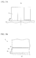
- the lateral strain is observed as a height h of a wave when the steel sheet unwound from the coil is disposed on a flat surface plate.
- a lateral strain portion 5e is a deformed region of the end portion of the steel sheet, which satisfies a condition where the height h of wave exceeds 2 mm or a condition where a steepness s expressed by the following Equation (1) exceeds 1.5% (exceeds 0.015).
- the lateral strain portion 5e cannot be used as a product, since it is trimmed by round cutter or the like when the coil is unwound after the final annealing. Therefore, as the lateral strain portion 5e increases, the trimming width increases, whereby there is a problem in that the yield decreases.
- S h / l
- 1 indicates the width of the lateral strain portion.
- a generation mechanism of the lateral strain at the time of the final annealing is explained by a grain boundary sliding at high temperatures. Specifically, at a high temperature of 900°C or more, the lateral strain caused by the grain boundary sliding becomes remarkable, such that in the grain boundary portion, lateral strain is apt to occur. A growing period of time of a secondary recrystallization in the lower end portion of the coil, which is brought into contact with the coil receiver, is slower than that in a center portion of the coil. Therefore, in the lower end portion of the coil, the grain size becomes small and thereby a refined grain portion is apt to be formed.
- Patent Citation 1 there is disclosed a method where before the final annealing, a grain refiner is applied onto a band-shaped portion having a predetermined width from a lower end face of the coil that is brought into contact with the coil receiver and grains in the band-shaped portion are refined during the final annealing.
- a method is disclosed where before the final annealing, a strain (deformation) is applied to the band-shaped portion having a predetermined width from the lower end face of the coil that is brought into contact with the coil receiver by a roller or the like on which protrusions are formed, and the grains in the band-shaped portion are refined during the final annealing.
- the width of the lateral strain portion which is the most deformed, is set as a trimming width, such that even when the width of the lateral strain portion is large only in one place, the trimming width increases and thereby the yield is diminished.
- the crystal grains in the lower end portion of the coil are refined using the strain caused through a mechanical working by the roller or the like as a starting point.
- the grain refining region may be controlled relatively well.
- the amount of strain (reduction ratio) applied diminishes with the passage of time and thereby the grain refining effect decreases.
- the grain-oriented electrical steel sheet is a hard material containing a large amount of Si, such that the abrasion in the roller is severe, and thereby it is necessary to frequently replace the roller.
- Patent Citations 3 to 6 a method is disclosed where in order to suppress the lateral strain, the secondary recrystallization in the band-shaped portion having a predetermined width from the lower end face of the coil is developed, grain size is made to quickly increase during the final annealing, and thereby high temperature strength is improved.
- Patent Citations 3 and 4 disclose a method where the band-shaped portion of the end portion of the steel sheet is heated by plasma heating or induction heating before the final annealing.
- Patent Citations 3, 5, and 6 a method is disclosed where the strain is introduced by a mechanical working using a shot blast, a roller, a tooth roller, or the like.
- the plasma heating and induction heating are heating methods in which a heating range is relatively wide, such that they are suitable to heat a band-shaped range.
- a heating range is relatively wide, such that they are suitable to heat a band-shaped range.
- it is difficult to control a heating position and a heating temperature.
- a region wider than a predetermined range is heated due to heat conduction. Therefore, it is difficult to constantly control the width of the region where the grain size increases by the secondary recrystallization, such that there is a problem in that non-uniformity may easily occur in the lateral strain suppressing effect.
- the strain application effect (amount of strain) is diminished with the passage of time due to the abrasion of the roller.
- the rate of the secondary recrystallization varies significantly depending on the amount of strain, such that there is problem in that it is difficult to obtain a predetermined grain size to stably obtain the lateral strain suppressing effect even when the amount of strain due to the abrasion of the roller is small.
- An object of the present invention is to solve the above-described problem in the conventional technique, and to suppress the lateral strain in the lower end portion of the coil that is brought into contact with the coil receiver inside the final annealing furnace, which is caused by a high temperature sliding in the final annealing.
- the present invention it is possible to provide a producing method of a grain-oriented electrical steel sheet where the suppression of a lateral strain may be stably and efficiently performed and the width of the lateral strain portion may be limited to be within a predetermined range.
- the inventors have intensively studied methods for solving the above-described problems. As a result, they have found that when a preferentially-deformable portion is formed to have a constant distance from an end face of the steel sheet, on a single face or both faces of an end region (first end portion) in one side of a steel sheet before the final annealing, the width of a lateral strain portion may be limited to be within a predetermined range. In addition, the preferentially-deformable portion is not formed at the end region (second end portion) at the other side of the steel sheet.
- the present invention has been made on the basis of the above-described finding, and the summery of the present invention is as follows.
- a producing method of a grain-oriented electrical steel sheet includes forming a preferentially-deformable portion at an end region of a steel sheet so as to be parallel with the rolling direction of the steel sheet; coiling the steel sheet; and performing a final annealing to the steel sheet after disposing the steel sheet in a manner such that the end region becomes the lower side of the steel sheet.
- the preferentially-deformable portion may be continuously formed.
- the preferentially-deformable portion may be discontinuously formed.
- the preferentially-deformable portion may be formed over the entire length of the steel sheet.
- the preferentially-deformable portion may be formed at a part of the steel sheet in the rolling direction.
- the preferentially-deformable portion may be formed at a distance of 5 to 100 mm from the end face of the end region.
- the steel sheet when the fmal annealing is performed, the steel sheet may be disposed in a manner such that the direction of the coil axis of the steel sheet after being wound into the coil shape becomes perpendicular to the coil receiver.
- the preferentially-deformable portion may be formed before an annealing separator is applied on the steel sheet.
- the preferentially-deformable portion may be formed by irradiation of a laser beam.
- a groove may be formed in the preferentially-deformable portion.
- the groove may be formed on a single face of the steel sheet.
- the groove may be formed on both faces of the steel sheet.
- the width of the groove may be from 0.03 to 10 mm.
- a depth d of the groove and a thickness t of the steel sheet may satisfy the equation 0.05 ⁇ d/t ⁇ 0.7.
- the preferentially-deformable portion may be a grain boundary sliding portion.
- the grain boundary sliding portion after the final annealing may be one linear crystal grain boundary.
- the grain boundary sliding portion after the final annealing may be a sliding band including crystal grains.
- the width of the sliding band may be from 0.02 to 20 mm.
- a thermally-deformed portion is formed at an end region of a steel sheet so as to be parallel with the rolling direction of the steel sheet.
- the thermally-deformed portion may be continuously formed.
- the thermally-deformed portion may be discontinuously formed.
- the thermally-deformed portion may be formed over the entire length of the steel sheet.
- the thermally-deformed portion may be formed at a part of the steel sheet in the rolling direction.
- the thermally-deformed portion may be formed at a distance of 5 to 100 mm from the end face of the end region.
- the thermally-deformed portion may be a groove.
- the groove may be formed on a single face of the steel sheet.
- the groove may be formed on both faces of the steel sheet.
- the width of the groove may be from 0.03 to 10 mm.
- a depth d of the groove and a thickness t of the steel sheet may satisfy the equation 0.05 ⁇ d/t ⁇ 0.7.
- the thermally-deformed portion may be one linear crystal grain boundary.
- the thermally-deformed portion may be a sliding band including crystal grains.
- the width of the sliding band may be from 0.02 to 20 mm.
- the preferentially-deformable portion which is formed in the lower end portion of the coil is preferentially deformed and the lateral strain developing from the lower end face of the coil is limited by the preferentially-deformable portion, so that the width of the lateral strain portion becomes a substantially constant value. Therefore, the trimming width in a post process may be reduced as much as possible, and thereby the yield is improved.
- a preferentially-deformable portion such as a groove and a grain boundary sliding portion at a high speed and with a free pattern using a laser beam. Furthermore, it is possible to perform a working using the laser beam without contacting a steel sheet, such that a problem caused by abrasion (time degradation) in a working device (working tool) such as a roller that is used in a mechanical working does not occur. That is, the amount of working does not vary with the passage of time, such that it is not necessary to replace the working device. Furthermore, it is possible to stably form the preferentially-deformable portion that is optimal for suppressing the lateral strain in a production line of a grain-oriented electrical steel sheet by controlling an irradiation energy density and a beam diameter of the laser beam.
- a preferentially-deformable portion 5f having a weak mechanical strength is formed along a rolling direction of the coil 5 (rolling direction of a steel sheet).
- the preferentially-deformable portion 5f is first deformed by buckling or sliding (slip), the load applied to a portion located in the upper direction of the preferentially-deformable portion 5f is dispersed, and thereby enlargement and variation in the width of the lateral strain portion are suppressed.
- the lateral strain portion is a deformation region of the end portion of the steel sheet, which satisfies a condition where the height h of a wave exceeds 2 mm or a condition where a steepness s expressed by the above Equation (1) exceeds 1.5% (exceeds 0.015).
- FIG. 2A shows a schematic diagram illustrating a growing process of the lateral strain portion 5e during a final annealing in a case where the preferentially-deformable portion 5f according to the present invention is not formed.
- FIG. 3B shows a schematic diagram illustrating a growing process of the lateral strain portion 5e during a final annealing in a case where the preferentially-deformable portion 5f according to the present invention is formed.
- FIGS. 2A shows a schematic diagram illustrating a growing process of the lateral strain portion 5e during a final annealing in a case where the preferentially-deformable portion 5f according to the present invention is formed.
- the solid line shows a schematic diagram in which the lower end portion of the coil at the time of the final annealing is enlarged
- the dotted line shows a schematic diagram in which the lower end portion of the coil after the final annealing is enlarged
- the broken line shows a schematic diagram in which the lower end portion of the coil before the final annealing is enlarged.
- a lateral strain portion 5e progresses from a lower end face of the coil 5 toward an upper side with the passage of annealing time (compare between the upper end position of the lateral strain portion 5e on the solid line and the upper end position of the lateral strain portion 5e on the dotted line).
- the width (length in the vertical direction) of the lateral strain portion 5e is enlarged according to the annealing time, and varies in the longitudinal direction (rolling direction) of the coil 5 due to non-uniformity in the strength of the coil 5 at high temperatures (secondary recrystallization).
- the lateral strain portion 5e does not progress from the preferentially-deformable portion 5f toward the upper side with the passage of annealing time (compare between the upper end position of the lateral strain portion 5e on the solid line and an upper end position of the lateral strain portion 5e on the dotted line). Accordingly, the width of the lateral strain portion 5e does not depend on the annealing time, and is determined by the position of the preferentially-deformable portion 5f. Furthermore, even for the non-uniformity in the strength of the coil 5 at high temperatures (secondary recrystallization), the width of the lateral strain portion 5e does not vary in the longitudinal direction (rolling direction) of the coil 5.
- the preferentially-deformable portion is formed at the end region (lower end portion of the coil) of the steel sheet so as to be parallel with the rolling direction of the steel sheet, such that the width of the lateral strain portion is limited, and thereby it is possible to improve the yield of the grain-oriented electrical steel sheet.
- the preferentially-deformable portion of the present invention is, for example, a groove portion having a groove or a grain boundary sliding portion described later.
- the preferentially-deformable portion is the groove portion, when the strength of the coil decreases at high temperatures, stress is concentrated on the groove portion and thereby the groove portion is preferentially deformed.
- the preferentially-deformable portion is the grain boundary sliding portion (slidable portion by a grain boundary)
- the grain boundary sliding portion preferentially causes a high temperature sliding (deformation).
- the preferentially-deformable portion is accurately formed within a predetermined narrow range to be parallel with an end face of the steel sheet so that the preferentially-deformable portion is preferentially deformed. Therefore, it is preferable that as a working device capable of condensing a section to be worked (for example, a laser irradiation section) to form the preferentially-deformable portion, for example, a laser device is used.
- a laser device is used as a working device capable of condensing a section to be worked (for example, a laser irradiation section) to form the preferentially-deformable portion.
- the width of the preferentially-deformable portion can be controlled within a predetermined narrow range by adjusting a condensing diameter of the laser beam.
- the condensed shape of the laser beam is an elliptical shape that has a diameter dc in the sheet width direction (C direction) and a diameter dL in the rolling direction (L direction).
- the energy density Ed input to the preferentially-deformable portion using the laser device is defined by the Equation (3) using a laser power P (W), the diameter dc (mm) in the sheet width direction(C direction) of the laser beam, and the feeding speed VL (mm/s) of a steel sheet.
- Ed 4 / ⁇ ⁇ P / dc ⁇ VL
- the energy density Ed is controlled according to the kind and shape of the preferentially-deformable portion as described later.
- the kind of laser is not specifically limited as long as the laser can form the preferentially-deformable portion with a predetermined shape on the surface of the steel sheet.
- a CO 2 laser, a YAG laser, a semiconductor laser, a fiber laser, or the like may be used.
- the preferentially-deformable portion formed by the working device may be continuously formed or may be formed over the entire length of the steel sheet in the rolling direction.
- the preferentially-deformable portion may be discontinuously formed or may be formed at a part of the steel sheet in the rolling direction.
- the preferentially-deformable portion which is continuous in the rolling direction, is formed.
- a discontinuous preferentially-deformable portion for example, a preferentially-deformable portion having a shape of a dotted line
- Preferentially-deformable portions may be formed in plural so as to be parallel with each other.
- FIG. 5 schematically shows an example of a first embodiment of the present invention to form the groove portion.
- a position spaced with a distance a from an end face in the width direction of the steel sheet (grain-oriented electrical steel sheet) 1 is irradiated with a laser beam 3 that is output from a laser device 2 and is condensed by a condensing lens 2a.
- the irradiated portion of the steel sheet is fused or vaporized.
- highly-pressurized assist gas 7 is injected from a nozzle 6 with respect to the irradiated portion to blow away the remaining fused material and thereby a groove portion 4a having a groove is formed.
- the steel sheet 1 is fed in the L direction (rolling direction) at a velocity VL, such that the groove portion 4a is formed along the rolling direction of the steel sheet.
- VL a velocity of the steel sheet.
- an annealing separator is applied onto the surface of the steel sheet 1, and the steel sheet 1 is wound as a coil 5.
- the fmal annealing is performed with respect to the coil 5 in a state where the end portion (end region), which has the groove portion 4a, of a coil-shaped steel sheet 1 faces the lower side.
- the coil-shaped steel sheet 1 is placed in a manner such that the coil axis 5a of the coil-shaped steel sheet 1 (coil 5) is vertical to the coil receiver 8 inside an annealing apparatus 9.
- the position (groove portion or working position) to be irradiated with the laser beam that is, a distance a at which the groove is to be formed is 100 mm or less from the end face (end face in the end region) of the steel sheet.
- the groove portion is formed at a distance of 30 mm or less from the end face in the end region of the steel sheet.
- the distance a may be determined according to the weight of the coil.
- the inventors found that even in a case of a large-scale coil having the largest sheet width, when the groove portion is formed at a position within 100 mm from the end face of the steel sheet, it is possible to suppress enlargement and variation in the width of the lateral strain portion in a practical operation.
- the groove portion is formed at a distance of 5 mm or more from the end face of the end region of the steel sheet.
- the groove portion is formed at a distance of 10 mm or more from the end face of the end region of the steel sheet.
- FIGS. 6A and 6B schematically show a cross-section of the groove formed according to the present invention.
- a groove having a groove width W and a groove depth d is formed on a single face of the steel sheet having a thickness t.
- one working device such as the laser device 2 of FIG. 5 may be used.
- the mechanical strength of the groove portion further decreases, such that the lateral strain suppressing effect is significantly further obtained.
- the shape of the groove of the groove portion with a low mechanical strength is designed in consideration of a sheet thickness of the steel sheet. Specifically, it is preferable that the groove is formed so that a ratio d/t of the depth d to the sheet thickness t satisfies the following Equation (4). 0.05 ⁇ d / t ⁇ 0.7
- the depths of the grooves formed on the front face and the rear face are set as d1 and d2, respectively, and a total depth (d1 + d2) of these grooves is set as d.
- the groove even when the depth of the groove formed on the front face of the steel sheet is relatively shallow, the groove has an effect on the mechanical strength of the groove portion of the steel sheet in an annealing process over an extended period at high temperatures.
- d/t when d/t is less than 0.05, even when the annealing is performed over an extended period at high temperatures, the mechanical strength of the groove portion does not decrease significantly, such that the lateral strain suppressing effect is not obtained. Therefore, in order to reliably obtain the lateral strain suppressing effect, it is preferable that d/t is 0.05 or more. More preferably, d/t is 0.1 or more.
- d/t is 0.7 or less. More preferably, d/t is 0.5 or less. Specifically, if a steel sheet with a thickness t of from 0.1 mm to 0.5 mm is used, it is preferable that the lower limit of the depth d is 0.005 mm, and more preferably, 0.01 mm. In addition, it is preferable that the upper limit of the depth d is 0.35 mm, and more preferably, 0.25 mm.
- the groove width W of the groove portion is from 0.03 mm to 10 mm.
- the groove width W is less than 0.03 mm, the mechanical strength in the groove portion does not decrease sufficiently, and the lateral strain suppressing effect is not obtained.
- the groove width W is greater than 10 mm, the mechanical strength of the groove portion decreases enormously, and thereby the coiling becomes difficult.
- the groove width can be controlled by adjusting the condensing diameter of the laser beam.
- the groove depth can be controlled by adjusting the laser power in combination with the feeding speed of the steel sheet. Therefore, in the present invention, when the laser beam is used, it is possible to easily form a groove, which has a shape suitable for suppressing the lateral strain, on a single face or both faces of the end region (first end portion) in one side of the steel sheet (grain-oriented electrical steel sheet) before the final annealing.
- the inventors have reviewed an optimal range of an energy density Ed of the laser device in a case of forming the groove portion using the laser device.
- the energy density Ed input to the groove portion by the laser device is defined by the above-described Equation (3).
- the energy density Ed As a result of experiment until now, when Ed is 0.5 J/mm 2 or more, the laser irradiation portion is fused, and thereby it is possible to form a groove portion with a sufficient groove depth. However, when Ed is less than 0.5 J/mm 2 , it is difficult to form the groove portion to be deformed preferentially during the final annealing. On the other hand, when Ed exceeds 5.0 J/mm 2 , the steel sheet is cut by the laser irradiation, and an energy efficiency decreases enormously. Therefore, the preferred range of Ed is a range expressed by the Equation (5).
- the energy density Ed is controlled to satisfy the Equation (5) by appropriately setting the laser power P, the diameter dc in the sheet width direction (C direction) of the laser beam and the feeding speed VL of the steel sheet.
- the working device for example, the laser device 2, condensing lens 2a and nozzle 6 shown in FIG. 5 ) does not come into contact with the steel sheet, such that it is possible to prevent a problem caused by time degradation of the working device.
- the laser device 2 is used as an example of the working device for forming the groove.
- any working device may be used as long as the working device can form a groove with a desired shape at high speed.
- a cutting device such as a water jet (injection device for a high pressure water stream with a fine diameter) or a reduction device such as a roller may be used to form the groove with the desired shape.
- the working device does not come into contact with the steel sheet during working like the laser device and time degradation does not occur. Therefore, in the first embodiment shown in FIG. 5 , a laser beam working is used, in which a non-contact type high speed working can be performed with superior power density and superior controllability.
- the preferentially-deformable portion is a grain boundary sliding portion (portion where a high temperature grain boundary sliding occurs by a secondary recrystallization during the final annealing).
- the inventors have found that when a locally heated section with a significantly narrow range is formed on the steel sheet before the final annealing, for example, by the irradiation of a condensed laser beam, a grain boundary of a secondary crystallization occurs easily in the heated section during the final annealing. In such a grain boundary, the grain boundary sliding occurs easily at high temperatures and the mechanical strength under high temperatures is decreased.
- the inventors arrived an idea that by forming a grain boundary sliding portion having a weak mechanical strength at a position on a coil that is spaced at a predetermined distance from the contact position of the coil and the coil receiver along the rolling direction of the coil (rolling direction of a steel sheet), the lateral strain (strain energy) to be formed from the lower end of the coil is absorbed by the deformation of the grain boundary sliding portion and the enlargement of the lateral strain toward the upper side from the grain boundary sliding portion is suppressed.
- the grain boundary sliding portion is a linear region where a high temperature sliding portion such a grain boundary is formed during the final annealing. Therefore, it is not necessarily necessary that the linear region includes the grain boundary before the final annealing.
- the high temperature sliding portion such as the grain boundary is formed in the grain boundary sliding portion at least after the final annealing.
- the grain boundary sliding portion (high temperature sliding portion) after the final annealing may be one grain boundary.
- the grain boundary sliding portion (high temperature sliding portion) after the final annealing may be a sliding band including crystal grains.
- the crystal grains may be long, thin crystal grains or fine crystal grains.
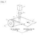
- FIG. 7 shows an example schematically illustrating a second embodiment for forming the grain boundary sliding portion.
- a laser beam 3 output from a laser device 2 is condensed by a condensing lens 2a, and a position away from an end face by a distance a in the width direction of the steel sheet 1 (grain-oriented electrical steel sheet) is irradiated with the laser beam.
- the steel sheet 1 is fed at a velocity VL in the L direction (rolling direction), such that the grain boundary sliding portion (linear region) 4z that is heated by the laser irradiation is formed along the rolling direction of the steel sheet.
- a velocity VL in the L direction (rolling direction)
- an annealing separator is applied onto a surface of the steel sheet 1
- the steel sheet 1 is wound into a coil 5.
- the coil 5 is placed on the coil receiver 8 in a manner such that the coil axis is vertically located and the end region (first end portion) including the laser irradiation portion becomes a lower side of the steel sheet, and then the final annealing is performed.
- an end region (second end portion) not including the laser irradiation portion becomes the upper side of the steel sheet.
- the steel sheet 1 is subjected to the final annealing in a state where the end region (first end portion) of the coil-shaped steel sheet 1 on which grain boundary sliding portion 4z is formed becomes a lower side.
- the coil-shaped steel sheet 1 is disposed in a manner such that the direction of the coil axis 5a of the coil-shaped steel sheet 1 (coil 5) becomes perpendicular to the coil receiver 8 inside the annealing apparatus 9.
- the grain boundary sliding portion is formed at a distance of 5 mm or more from the end face of the end region of the steel sheet so that the strain energy of the lateral strain portion is sufficiently absorbed by the deformation of the grain boundary sliding portion.
- the grain boundary sliding portion is formed at a distance of 10 mm or more from the end face of the end region of the steel sheet.
- the distance a from the end face of the steel sheet to the grain boundary sliding portion is 100 mm or less.
- the groove portion is formed at a distance of 30 mm or less from the end face of the end region of the steel sheet. In order to optimize the yield, the distance a may be determined according to the weight of the coil.
- the width of the sliding band is 20 mm or less.
- the width of the sliding band is larger than 20 mm, the mechanical strength of the sliding band increases, such that the sliding band does not act as the preferentially-deformable portion (grain boundary sliding portion) during the final annealing.
- the lower limit of the width of the sliding band is not specifically defined. However, since the crystal grains have a size of 0.02 mm before the final annealing, the lower limit of the width of the sliding band may be 0.02 mm.
- the width of the sliding band is obtained by averaging the width of the sliding band at each position of the sliding band in the rolling direction.
- the sliding band is defined as the linear portion with crystal grains.
- the inventors have reviewed an optimal range of an energy density Ed of the laser device in a case of forming the grain boundary sliding portion using the laser device.
- the energy density Ed input to the grain boundary sliding portion 4z by the laser device 2 is defined by the above-described Equation (3).
- a preferred range of the Ed is within a range expressed by the Equation (6).
- the energy density Ed is controlled to satisfy the Equation (6) by appropriately setting the laser power P, the diameter dc in the sheet width direction (C direction) of the laser beam, and the feeding speed VL of the steel sheet. It is preferable that the grain boundary sliding portion is formed over the entire sheet thickness. Therefore, in addition to the energy density Ed, the diameter dL in the rolling direction (L direction) may be controlled according to the feeding speed VL of the steel sheet so that a predetermined heating time is maintained.
- the working device that forms the grain boundary sliding portion 4z may be a heating device capable of condensing a heating section.
- the grain boundary sliding portion for example, a linear grain boundary at the time of the final annealing
- a laser beam that is superior in controllability of the heating position and heating rate is used.
- the groove or the grain boundary sliding portion is formed on the steel sheet.
- both of the groove and the slip deformation portion may be formed.
- a process of forming the preferentially-deformable portion at the end region of the steel sheet so as to be parallel with the rolling direction of the steel sheet, a process of coiling the steel sheet into a coil shape, and a process of performing the final annealing in a state where the end region of the coil-shaped steel sheet becomes the lower side of the steel sheet are sequentially performed. Furthermore, the process of forming the preferentially-deformable portion is performed after cold rolling. In addition, it is preferable that the process of forming the preferentially-deformable portion on the steel sheet is performed before the process of applying the annealing separator in order to prevent the loss of the annealing separator.
- the thermally-deformed portion (hot-deformed portion, the preferentially-deformable portion after the final annealing) is formed at the end region of the steel sheet to be parallel with the rolling direction of the steel sheet.
- the thermally-deformed portion may be formed continuously or discontinuously.
- the thermally-deformed portion may be formed over the entire length of the steel sheet, or may be formed at a part of the steel sheet in the rolling direction thereof.
- it is preferable that the thermally-deformed portion is formed at a distance of 5 to 100 mm from the end face of the end region.
- the above-described thermally-deformed portion may be a groove.
- the groove may be formed on a single face or both faces of the steel sheet.
- the width of the groove is from 0.03 mm to 10 mm.
- the depth d of the groove and the thickness t of the steel sheet satisfy the above-described Equation (4).
- the above-described thermally-deformed portion may be a single linear crystal grain boundary or a sliding band including a crystal grains. It is preferable that the width of the sliding band is from 0.02 mm to 20 mm.
- the above-described grain-oriented electrical steel sheet is used after the deformation region adjacent to the thermally-deformed portion is cut out.
- a CO 2 laser was used as the laser device 2 in FIG. 5 .
- a laser power P was controlled to be 1500 W by an electrical input and a condensing shape of the laser was a circular shape with 0.2 mm ⁇ .
- a steel sheet (grain-oriented electrical steel sheet) 1 with a width of 1000 mm and a thickness t of 0.23 mm after decarburization annealing was fed at a velocity VL of 1000 mm/s in the L direction.
- a distance a which is a laser beam irradiation position, was spaced by 20 mm from an end face of the steel sheet, a surface in one side of the steel sheet was irradiated with a laser beam over the entire length of the coil (entire length in the L direction), and thereby a groove was formed.
- assist gas dried air under a pressure of 0.5 MPa was used.
- the cross-sectional shape of the formed groove portion had dimensions: a width W of substantially 0.2 mm and a depth d of substantially 0.02 mm. In this case, an energy density Ed of the laser beam was 9.5 J/mm 2 .
- the coil-shaped steel sheet (coil) was subjected to a final annealing at substantially 1200°C for substantially 20 hours using the annealing apparatus shown in FIG. 1 (Example 1).
- a coil (non-processed coil) in which the groove was not formed was subjected to the same final annealing as described above. The width of the lateral strain of the steel sheet after the final annealing was visually inspected over the entire length of the coil.
- the width of a deformation region of the end portion of the steel sheet as the lateral strain portion which satisfies a condition where the height h of wave exceeds 2 mm or a condition where a steepness s expressed by the above-described Equation (1) exceeds 1.5% (exceeds 0.015), was measured.
- Results thereof are shown in Table 1.
- Table 1 in the Comparative example where the groove was not formed, the width of the lateral strain portion was wide, as well as variation in the width of the lateral strain portion being large with a value of 40 mm ( ⁇ 20 mm). Especially, lateral strain having a width up to substantially 60 mm was generated and the yield decreased largely.
- Example 1 where the groove portion was formed at a position spaced by distance a from an end face of the coil according to the first embodiment of the present invention, a relatively remarkable bending deformation (buckling distortion) was generated at a position of 20 mm corresponding to the distance a.
- a semiconductor laser was used as the laser device 2 of FIG. 7 .
- a laser power P could be changed up to 2 kW.
- the laser power P could be arbitrarily set using a laser power control device (not shown).
- the laser power P was set to 1000 W, and a condensing shape was set to an elliptical shape where dc was 1.2 mm, and dL was 12 mm.
- the energy density Ed of the laser beam was 2.7 J/mm 2 .
- the coil-shaped steel sheet (coil) was subjected to a final annealing at substantially 1200°C for substantially 20 hours using the annealing apparatus shown in FIG. 1 (Example 2).
- a coil (non-processed coil) to which the laser irradiation was not performed was subjected to the same final annealing as described above. The width of a lateral strain of the steel sheet after the final annealing was visually inspected over the entire length of the coil.
- FIGS. 8A, 8B and 8C show observation results of a crystalline structure of the steel sheet, after the surface of the steel sheet after the final annealing was washed using an acid and thereby a film thereof was removed.
- FIG. 8A is an image of a metallographic structure at the vicinity of the grain boundary sliding portion that was subjected to the laser irradiation according to the second embodiment of the present invention.
- FIG. 8C is an image of a metallographic structure that was not subjected to the laser irradiation as the Comparative example.
- FIG. 8B shows a modified example where the laser irradiation was performed with the same conditions as the second embodiment and the final annealing time was shorter than that in the second embodiment.
- a sliding band 12 including crystal grains was formed.
- the crystal grains in the sliding band were long, thin crystal grains.
- the grain boundary sliding portion after the final annealing is the linear crystal grain boundary 10 or the sliding band 12 including the crystal grains.
- the sliding band 12 including the crystal grains is apt to be generated in a case where for example, the energy density of the laser beam is low or the annealing time is short compared to conditions where the linear crystal grain boundary 10 is formed.
- the conditions where the linear crystal grain boundary 10 is generated and the conditions where the sliding band including the crystal grains 12 is generated also vary depending on the chemical composition of the steel sheet, the temperature of the final annealing, the time of the final annealing, the atmosphere of the final annealing, in addition to the laser conditions, such as the energy density of the laser beam, such that the details of the conditions are unclear.
- the grain boundary sliding is apt to be generated at high temperatures of 900°C or more during the final annealing, and the mechanical strength thereof is lower than that of other portions. Therefore, it is considered that when a load is applied to the coil in a state where the coil is brought into contact with the coil receiver, the linear crystal grain boundary 10 is at first deformed due to sliding, the load applied to the upper side in relation to the crystal grain boundary 10 is dispersed, and thereby the enlargement and variation in the width of the lateral strain portion are suppressed.
- the sliding mechanism at the time of the above-described annealing depends on the linear crystal grain boundary formed at the grain boundary sliding portion.
- the sliding mechanism may be, for example, a high temperature sliding due to a sliding band that is formed along the rolling direction and includes the crystal grains.
- the crystal grains may be fine crystal grains or long, thin crystal grains.
- the grain boundary of crystal grains (long, thin crystal grains) in the sliding band 12 is deformed due to sliding similarly to the above-described linear crystal grain boundary 10 and thereby the enlargement and variation of the lateral strain portion is suppressed.
- the inventors investigated a preferred range of the energy density Ed of the laser irradiation in the second embodiment. That is, the inventors investigated the relationship between the degree of grain refining in the laser irradiation portion and the energy density Ed under a condition where the distance a was 20 mm.
- the feeding speed VL was set to 1000 mm/s
- the diameter dc of the laser beam in the C direction was set to a constant value of 1.2 mm.
- the Ed expressed by the above-described Equation (3) was changed by changing the laser power P within a range of 200 to 5000 W and then investigated a crystal state (metallographic structure) of the steel sheet after the secondary recrystallization.
- the energy density Ed was 0.5 J/mm 2 or more, it was possible to generate a predetermined crystalline structure (linear grain boundary) at the time of the final annealing.
- the energy density Ed was less than 0.5 J/mm 2 , it was difficult to generate a predetermined crystalline structure (linear grain boundary) at the time of the final annealing.
- the energy density Ed exceeded 5.0 J/mm 2 , the steel sheet was fused remarkably by the laser irradiation, and the steel sheet was largely deformed at the time of re-solidification. Accordingly, there was a problem that the steel sheet could not be wound into the coil. Therefore, the preferred range of the Ed was within the range expressed by the Equation (6).
- the width of the lateral strain portion is made to be nearly constant value, the trimming width in the post process can be diminished as much as possible, and the yield is improved. Therefore, the industrial applicability in the manufacture of the electromagnetic steel sheet is high.
Landscapes
- Chemical & Material Sciences (AREA)
- Engineering & Computer Science (AREA)
- Physics & Mathematics (AREA)
- Materials Engineering (AREA)
- Organic Chemistry (AREA)
- Thermal Sciences (AREA)
- Crystallography & Structural Chemistry (AREA)
- Mechanical Engineering (AREA)
- Metallurgy (AREA)
- Electromagnetism (AREA)
- Manufacturing & Machinery (AREA)
- Dispersion Chemistry (AREA)
- Power Engineering (AREA)
- Optics & Photonics (AREA)
- Manufacturing Of Steel Electrode Plates (AREA)
- Soft Magnetic Materials (AREA)
- Heat Treatment Of Articles (AREA)
Abstract
Description
- The present invention relates to a method of manufacturing a grain-oriented electrical steel sheet, which prevents lateral strain of a coil end portion brought into contact with a coil receiver in final annealing.
Priority is claimed on Japanese Patent Application No.2009-058500, filed March 11, 2009 2009-263216, filed November 18, 2009 - In a method of manufacturing a grain-oriented electrical steel sheet, a cold-rolled steel sheet is wound in a coil after decarburization annealing, and is subject to a final annealing for the purpose of a secondary recrystallization at high temperatures of 1000°C or higher. At the time of the final annealing, as shown in
FIG. 1 , acoil 5 is disposed on acoil receiver 8 in an annealing furnace cover 9 in a manner such that thecoil axis 5a of thecoil 5 becomes vertical. - When the
coil 5 placed as described above is annealed at high temperatures, as shown inFIG. 2A , in alower end portion 5z of thecoil 5 brought into contact with thecoil receiver 8, a buckling distortion called lateral strain is caused by the weight of thecoil 5, a difference between the thermal expansions of thecoil 5 and thecoil receiver 8, or the like. As shown inFIG. 2B , the lateral strain is observed as a height h of a wave when the steel sheet unwound from the coil is disposed on a flat surface plate. In general, alateral strain portion 5e is a deformed region of the end portion of the steel sheet, which satisfies a condition where the height h of wave exceeds 2 mm or a condition where a steepness s expressed by the following Equation (1) exceeds 1.5% (exceeds 0.015). Thelateral strain portion 5e cannot be used as a product, since it is trimmed by round cutter or the like when the coil is unwound after the final annealing. Therefore, as thelateral strain portion 5e increases, the trimming width increases, whereby there is a problem in that the yield decreases.
Here, 1 indicates the width of the lateral strain portion. - A generation mechanism of the lateral strain at the time of the final annealing is explained by a grain boundary sliding at high temperatures. Specifically, at a high temperature of 900°C or more, the lateral strain caused by the grain boundary sliding becomes remarkable, such that in the grain boundary portion, lateral strain is apt to occur. A growing period of time of a secondary recrystallization in the lower end portion of the coil, which is brought into contact with the coil receiver, is slower than that in a center portion of the coil. Therefore, in the lower end portion of the coil, the grain size becomes small and thereby a refined grain portion is apt to be formed.
- It is assumed that since many crystal grain boundaries are present in the refined grain portion, the grain boundary sliding occurs easily and thereby the lateral strain occurs. Accordingly, in the conventional technique, various methods have been suggested for suppressing a mechanical deformation by controlling crystal grain growth in the lower end portion of the coil.
- In Patent Citation 1, there is disclosed a method where before the final annealing, a grain refiner is applied onto a band-shaped portion having a predetermined width from a lower end face of the coil that is brought into contact with the coil receiver and grains in the band-shaped portion are refined during the final annealing. In addition, in
Patent Citation 2, a method is disclosed where before the final annealing, a strain (deformation) is applied to the band-shaped portion having a predetermined width from the lower end face of the coil that is brought into contact with the coil receiver by a roller or the like on which protrusions are formed, and the grains in the band-shaped portion are refined during the final annealing. - As described above, in the methods disclosed in Patent Citation 1 and Patent Citation 2, in order to suppress the lateral strain, the crystal grains in the lower end portion of the coil are intentionally refined and thereby the mechanical strength in the lower end portion of the coil is changed.
- However, in the method where the grain refiner is applied, which is disclosed in Patent Citation 1, since the grain refiner is in the form of liquid, it is difficult to accurately control the application region. In addition, the grain refiner may be diffused from the end portion of the steel sheet toward the center portion of the steel sheet. Therefore, it is difficult to constantly control the width of a grain refining region, such that the width of the lateral strain portion may vary greatly in a longitudinal direction of the coil.
- The width of the lateral strain portion, which is the most deformed, is set as a trimming width, such that even when the width of the lateral strain portion is large only in one place, the trimming width increases and thereby the yield is diminished.
- In addition, in the method where the strain is applied, which is disclosed in Patent Citation 2, the crystal grains in the lower end portion of the coil are refined using the strain caused through a mechanical working by the roller or the like as a starting point. In this method, the grain refining region may be controlled relatively well. However, there is a problem in that since the roller is abraded due to continuously working over an extended period of time, the amount of strain (reduction ratio) applied diminishes with the passage of time and thereby the grain refining effect decreases. Particularly, the grain-oriented electrical steel sheet is a hard material containing a large amount of Si, such that the abrasion in the roller is severe, and thereby it is necessary to frequently replace the roller.
- On the other hand, in
Patent Citations 3 to 6, a method is disclosed where in order to suppress the lateral strain, the secondary recrystallization in the band-shaped portion having a predetermined width from the lower end face of the coil is developed, grain size is made to quickly increase during the final annealing, and thereby high temperature strength is improved. - As means for making the grain size large,
Patent Citations 3 and 4 disclose a method where the band-shaped portion of the end portion of the steel sheet is heated by plasma heating or induction heating before the final annealing. In addition, inPatent Citations - The plasma heating and induction heating are heating methods in which a heating range is relatively wide, such that they are suitable to heat a band-shaped range. However, there is a problem in that in the plasma heating and induction heating, it is difficult to control a heating position and a heating temperature. In addition, there is a problem in that a region wider than a predetermined range is heated due to heat conduction. Therefore, it is difficult to constantly control the width of the region where the grain size increases by the secondary recrystallization, such that there is a problem in that non-uniformity may easily occur in the lateral strain suppressing effect.
- In the method performed by a mechanical working using the roller or the like, as described above, there is a problem in that the strain application effect (amount of strain) is diminished with the passage of time due to the abrasion of the roller. Specifically, the rate of the secondary recrystallization varies significantly depending on the amount of strain, such that there is problem in that it is difficult to obtain a predetermined grain size to stably obtain the lateral strain suppressing effect even when the amount of strain due to the abrasion of the roller is small.
-
- [Patent Citation 1] Japanese Unexamined Patent Application, First Publication No.
S63-100131 - [Patent Citation 2] Japanese Unexamined Patent Application, First Publication No.
S64-042530 - [Patent Citation 3] Japanese Unexamined Patent Application, First Publication No.
H02-097622 - [Patent Citation 4] Japanese Unexamined Patent Application, First Publication No.
H03-177518 - [Patent Citation 5] Japanese Unexamined Patent Application, First Publication No.
2000-038616 - [Patent Citation 6] Japanese Unexamined Patent Application, First Publication No.
2001-323322 - As described above, in the conventional technique, there is problem that since it is difficult to precisely perform the control (range and size) of the crystal grain size, it is difficult to obtain a sufficient lateral strain suppressing effect.
An object of the present invention is to solve the above-described problem in the conventional technique, and to suppress the lateral strain in the lower end portion of the coil that is brought into contact with the coil receiver inside the final annealing furnace, which is caused by a high temperature sliding in the final annealing. - That is, in the present invention, it is possible to provide a producing method of a grain-oriented electrical steel sheet where the suppression of a lateral strain may be stably and efficiently performed and the width of the lateral strain portion may be limited to be within a predetermined range.
- The inventors have intensively studied methods for solving the above-described problems. As a result, they have found that when a preferentially-deformable portion is formed to have a constant distance from an end face of the steel sheet, on a single face or both faces of an end region (first end portion) in one side of a steel sheet before the final annealing, the width of a lateral strain portion may be limited to be within a predetermined range. In addition, the preferentially-deformable portion is not formed at the end region (second end portion) at the other side of the steel sheet.
- The present invention has been made on the basis of the above-described finding, and the summery of the present invention is as follows.
- (1) A producing method of a grain-oriented electrical steel sheet includes forming a preferentially-deformable portion at an end region of a steel sheet so as to be parallel with the rolling direction of the steel sheet; coiling the steel sheet; and performing a final annealing to the steel sheet after disposing the steel sheet in a manner such that the end region becomes the lower side of the steel sheet.
- (2) In the producing method of a grain-oriented electrical steel sheet according to (1), the preferentially-deformable portion may be continuously formed.
- (3) In the producing method of a grain-oriented electrical steel sheet according to (1), the preferentially-deformable portion may be discontinuously formed.
- (4) In the producing method of a grain-oriented electrical steel sheet according to (1), the preferentially-deformable portion may be formed over the entire length of the steel sheet.
- (5) In the producing method of a grain-oriented electrical steel sheet according to (1), the preferentially-deformable portion may be formed at a part of the steel sheet in the rolling direction.
- (6) In the producing method of a grain-oriented electrical steel sheet according to (1), the preferentially-deformable portion may be formed at a distance of 5 to 100 mm from the end face of the end region.
- (7) In the producing method of a grain-oriented electrical steel sheet according to (1), when the fmal annealing is performed, the steel sheet may be disposed in a manner such that the direction of the coil axis of the steel sheet after being wound into the coil shape becomes perpendicular to the coil receiver.
- (8) In the producing method of a grain-oriented electrical steel sheet according to (1), the preferentially-deformable portion may be formed before an annealing separator is applied on the steel sheet.
- (9) In the producing method of a grain-oriented electrical steel sheet according to (1), the preferentially-deformable portion may be formed by irradiation of a laser beam.
- (10) In the producing method of a grain-oriented electrical steel sheet according to (1), a groove may be formed in the preferentially-deformable portion.
- (11) In the producing method of a grain-oriented electrical steel sheet according to (10), the groove may be formed on a single face of the steel sheet.
- (12) In the producing method of a grain-oriented electrical steel sheet according to (10), the groove may be formed on both faces of the steel sheet.
- (13) In the producing method of a grain-oriented electrical steel sheet according to (10), the width of the groove may be from 0.03 to 10 mm.
- (14) In the producing method of a grain-oriented electrical steel sheet according to (10), a depth d of the groove and a thickness t of the steel sheet may satisfy the equation 0.05 ≤ d/t ≤ 0.7.
- (15) In the producing method of a grain-oriented electrical steel sheet according to (1), the preferentially-deformable portion may be a grain boundary sliding portion.
- (16) In the producing method of a grain-oriented electrical steel sheet according to (15), the grain boundary sliding portion after the final annealing may be one linear crystal grain boundary.
- (17) In the producing method of a grain-oriented electrical steel sheet according to (15), the grain boundary sliding portion after the final annealing may be a sliding band including crystal grains.
- (18) In the producing method of a grain-oriented electrical steel sheet according to (17), the width of the sliding band may be from 0.02 to 20 mm.
- (19) In a grain-oriented electrical steel sheet, a thermally-deformed portion is formed at an end region of a steel sheet so as to be parallel with the rolling direction of the steel sheet.
- (20) In the grain-oriented electrical steel sheet according to (19), the thermally-deformed portion may be continuously formed.
- (21) In the grain-oriented electrical steel sheet according to (19), the thermally-deformed portion may be discontinuously formed.
- (22) In the grain-oriented electrical steel sheet according to (19), the thermally-deformed portion may be formed over the entire length of the steel sheet.
- (23) In the grain-oriented electrical steel sheet according to (19), the thermally-deformed portion may be formed at a part of the steel sheet in the rolling direction.
- (24) In the grain-oriented electrical steel sheet according to (19), the thermally-deformed portion may be formed at a distance of 5 to 100 mm from the end face of the end region.
- (25) In the grain-oriented electrical steel sheet according to (19), the thermally-deformed portion may be a groove.
- (26) In the grain-oriented electrical steel sheet according to (25), the groove may be formed on a single face of the steel sheet.
- (27) In the grain-oriented electrical steel sheet according to (25), the groove may be formed on both faces of the steel sheet.
- (28) In the grain-oriented electrical steel sheet according to (25), the width of the groove may be from 0.03 to 10 mm.
- (29) In the grain-oriented electrical steel sheet according to (25), a depth d of the groove and a thickness t of the steel sheet may satisfy the equation 0.05 ≤ d/t ≤ 0.7.
- (30) In the grain-oriented electrical steel sheet according to (19), the thermally-deformed portion may be one linear crystal grain boundary.
- (31) In the grain-oriented electrical steel sheet according to (19), the thermally-deformed portion may be a sliding band including crystal grains.
- (32) In the grain-oriented electrical steel sheet according to (31); the width of the sliding band may be from 0.02 to 20 mm.
- According to the present invention, during the final annealing, the preferentially-deformable portion which is formed in the lower end portion of the coil is preferentially deformed and the lateral strain developing from the lower end face of the coil is limited by the preferentially-deformable portion, so that the width of the lateral strain portion becomes a substantially constant value. Therefore, the trimming width in a post process may be reduced as much as possible, and thereby the yield is improved.
- In addition, according to the present invention, it is possible to form a preferentially-deformable portion such as a groove and a grain boundary sliding portion at a high speed and with a free pattern using a laser beam. Furthermore, it is possible to perform a working using the laser beam without contacting a steel sheet, such that a problem caused by abrasion (time degradation) in a working device (working tool) such as a roller that is used in a mechanical working does not occur. That is, the amount of working does not vary with the passage of time, such that it is not necessary to replace the working device. Furthermore, it is possible to stably form the preferentially-deformable portion that is optimal for suppressing the lateral strain in a production line of a grain-oriented electrical steel sheet by controlling an irradiation energy density and a beam diameter of the laser beam.
-
-
FIG. 1 is a diagram illustrating an example of a final annealing apparatus. -
FIG. 2A is a schematic diagram illustrating a growing process of a lateral strain in a case where a preferentially-deformable portion is not formed. -
FIG. 2B is a diagram illustrating an example of an evaluation method of a lateral strain of the present invention. -
FIG. 3A is an explanatory diagram illustrating a position of the preferentially-deformable portion. -
FIG. 3B is a schematic diagram illustrating a growing process of a lateral strain during a final annealing in a case where a preferentially-deformable portion is formed. -
FIG. 4 is a diagram illustrating an example of a condensed shape of a laser beam. -
FIG. 5 is a diagram schematically illustrating an example of a first embodiment of the present invention. -
FIG. 6A is a diagram schematically illustrating the cross-sectional shape of a groove formed on a single face of an end region of a steel sheet. -
FIG. 6B is a diagram schematically illustrating the cross-sectional shape of grooves formed on both faces of an end region of a steel sheet. -
FIG. 7 is a diagram schematically illustrating an example of a second embodiment of the present invention. -
FIG. 8A is an image of a metallographic structure that is adjacent to a grain boundary sliding portion subjected to a laser irradiation performed according to the second embodiment. -
FIG. 8B is an image of a metallographic structure that is adjacent to a grain boundary sliding portion subjected to a laser irradiation performed according to a modified example of the second embodiment. -
FIG. 8C is an image of a metallographic structure to which a laser irradiation is not performed. - Hereinafter, exemplary embodiments of the present invention will be described in detail with reference to the accompanying drawings. Further, in this specification and the accompanying drawings, like reference symbols will be given to like components having substantially the same functions, and redundant description thereof will be omitted.
- In the present invention, as shown in
FIG. 3A , at a position on a coil that is spaced at a predetermined distance from a contact position of acoil 5 and acoil receiver 8, a preferentially-deformable portion 5f having a weak mechanical strength is formed along a rolling direction of the coil 5 (rolling direction of a steel sheet). In a case where a load is applied to thecoil 5 in a high temperature annealing furnace, the preferentially-deformable portion 5f is first deformed by buckling or sliding (slip), the load applied to a portion located in the upper direction of the preferentially-deformable portion 5f is dispersed, and thereby enlargement and variation in the width of the lateral strain portion are suppressed. In addition, the lateral strain portion is a deformation region of the end portion of the steel sheet, which satisfies a condition where the height h of a wave exceeds 2 mm or a condition where a steepness s expressed by the above Equation (1) exceeds 1.5% (exceeds 0.015). - Next, an effect of the preferentially-
deformable portion 5f in a method of manufacturing the grain-oriented electrical steel sheet of the present invention will be described in detail usingFIGS. 2A and3B .FIG. 2A shows a schematic diagram illustrating a growing process of thelateral strain portion 5e during a final annealing in a case where the preferentially-deformable portion 5f according to the present invention is not formed.FIG. 3B shows a schematic diagram illustrating a growing process of thelateral strain portion 5e during a final annealing in a case where the preferentially-deformable portion 5f according to the present invention is formed. In addition, inFIGS. 2A and3B , the solid line shows a schematic diagram in which the lower end portion of the coil at the time of the final annealing is enlarged, the dotted line shows a schematic diagram in which the lower end portion of the coil after the final annealing is enlarged, and the broken line shows a schematic diagram in which the lower end portion of the coil before the final annealing is enlarged. As shown inFIG. 2A , if the preferentially-deformable portion 5f is not formed in thecoil 5, alateral strain portion 5e progresses from a lower end face of thecoil 5 toward an upper side with the passage of annealing time (compare between the upper end position of thelateral strain portion 5e on the solid line and the upper end position of thelateral strain portion 5e on the dotted line). The width (length in the vertical direction) of thelateral strain portion 5e is enlarged according to the annealing time, and varies in the longitudinal direction (rolling direction) of thecoil 5 due to non-uniformity in the strength of thecoil 5 at high temperatures (secondary recrystallization). - However, as shown in
FIG. 3B , when the preferentially-deformable portion 5f is formed on thecoil 5, the preferentially-deformable portion 5f is preferentially deformed. Therefore, thelateral strain portion 5e does not progress from the preferentially-deformable portion 5f toward the upper side with the passage of annealing time (compare between the upper end position of thelateral strain portion 5e on the solid line and an upper end position of thelateral strain portion 5e on the dotted line). Accordingly, the width of thelateral strain portion 5e does not depend on the annealing time, and is determined by the position of the preferentially-deformable portion 5f. Furthermore, even for the non-uniformity in the strength of thecoil 5 at high temperatures (secondary recrystallization), the width of thelateral strain portion 5e does not vary in the longitudinal direction (rolling direction) of thecoil 5. - As described above, in the present invention, the preferentially-deformable portion is formed at the end region (lower end portion of the coil) of the steel sheet so as to be parallel with the rolling direction of the steel sheet, such that the width of the lateral strain portion is limited, and thereby it is possible to improve the yield of the grain-oriented electrical steel sheet.
- In addition, a specific example of the preferentially-deformable portion of the present invention will be described. It is necessary that the mechanical strength of the preferentially-deformable portion at the time of the final annealing is made to be sufficiently small so that the preferentially-deformable portion shows the above-described effect. In the present invention, the preferentially-deformable portion is, for example, a groove portion having a groove or a grain boundary sliding portion described later. In a case where the preferentially-deformable portion is the groove portion, when the strength of the coil decreases at high temperatures, stress is concentrated on the groove portion and thereby the groove portion is preferentially deformed. In addition, when the preferentially-deformable portion is the grain boundary sliding portion (slidable portion by a grain boundary), the grain boundary sliding portion preferentially causes a high temperature sliding (deformation).
- It is necessary that the preferentially-deformable portion is accurately formed within a predetermined narrow range to be parallel with an end face of the steel sheet so that the preferentially-deformable portion is preferentially deformed. Therefore, it is preferable that as a working device capable of condensing a section to be worked (for example, a laser irradiation section) to form the preferentially-deformable portion, for example, a laser device is used. When the preferentially-deformable portion is formed using the laser device, the width of the preferentially-deformable portion can be controlled within a predetermined narrow range by adjusting a condensing diameter of the laser beam. As shown in
FIG. 4 , the condensed shape of the laser beam is an elliptical shape that has a diameter dc in the sheet width direction (C direction) and a diameter dL in the rolling direction (L direction). - Here, it is necessary that the laser irradiation section is spaced from the end face of the steel sheet so as to satisfy the following Equation (2).

- In addition, the energy density Ed input to the preferentially-deformable portion using the laser device is defined by the Equation (3) using a laser power P (W), the diameter dc (mm) in the sheet width direction(C direction) of the laser beam, and the feeding speed VL (mm/s) of a steel sheet.

- In addition, the kind of laser is not specifically limited as long as the laser can form the preferentially-deformable portion with a predetermined shape on the surface of the steel sheet. For example, a CO2 laser, a YAG laser, a semiconductor laser, a fiber laser, or the like may be used.
- In addition, the preferentially-deformable portion formed by the working device may be continuously formed or may be formed over the entire length of the steel sheet in the rolling direction. However, for energy saving, the preferentially-deformable portion may be discontinuously formed or may be formed at a part of the steel sheet in the rolling direction. For example, when a continuous-wave laser beam is used, the preferentially-deformable portion, which is continuous in the rolling direction, is formed. In addition, for example, when a pulse laser is used, a discontinuous preferentially-deformable portion (for example, a preferentially-deformable portion having a shape of a dotted line) is formed. Preferentially-deformable portions may be formed in plural so as to be parallel with each other.
- Hereinafter, first, description will be given with respect to a case where the preferentially-deformable portion is a groove portion.
FIG. 5 schematically shows an example of a first embodiment of the present invention to form the groove portion. - In the first embodiment shown in
FIG. 5 , a position spaced with a distance a from an end face in the width direction of the steel sheet (grain-oriented electrical steel sheet) 1 is irradiated with alaser beam 3 that is output from alaser device 2 and is condensed by a condensinglens 2a. By the irradiation of thelaser beam 3, the irradiated portion of the steel sheet is fused or vaporized. Furthermore, highly-pressurizedassist gas 7 is injected from a nozzle 6 with respect to the irradiated portion to blow away the remaining fused material and thereby a groove portion 4a having a groove is formed. - The steel sheet 1 is fed in the L direction (rolling direction) at a velocity VL, such that the groove portion 4a is formed along the rolling direction of the steel sheet. After the groove portion 4a is formed on the steel sheet 1, an annealing separator is applied onto the surface of the steel sheet 1, and the steel sheet 1 is wound as a
coil 5. - As shown in
FIG. 1 , the fmal annealing is performed with respect to thecoil 5 in a state where the end portion (end region), which has the groove portion 4a, of a coil-shaped steel sheet 1 faces the lower side. In the final annealing, it is preferable that the coil-shaped steel sheet 1 is placed in a manner such that thecoil axis 5a of the coil-shaped steel sheet 1 (coil 5) is vertical to thecoil receiver 8 inside an annealing apparatus 9. - In order to improve the yield of the grain-oriented electrical steel sheet, it is preferable that the position (groove portion or working position) to be irradiated with the laser beam, that is, a distance a at which the groove is to be formed is 100 mm or less from the end face (end face in the end region) of the steel sheet. In order to further improve the yield, more preferably, the groove portion is formed at a distance of 30 mm or less from the end face in the end region of the steel sheet. In order to optimize the yield, the distance a may be determined according to the weight of the coil. The inventors found that even in a case of a large-scale coil having the largest sheet width, when the groove portion is formed at a position within 100 mm from the end face of the steel sheet, it is possible to suppress enlargement and variation in the width of the lateral strain portion in a practical operation.
In addition, in order to produce the effect of the groove portion without the contact between the groove portion and the coil receiver, it is preferable that the groove portion is formed at a distance of 5 mm or more from the end face of the end region of the steel sheet. In order to further secure the effect of the groove portion, it is preferable that the groove portion is formed at a distance of 10 mm or more from the end face of the end region of the steel sheet. -
FIGS. 6A and 6B schematically show a cross-section of the groove formed according to the present invention. InFIG. 6A , a groove having a groove width W and a groove depth d is formed on a single face of the steel sheet having a thickness t. InFIG. 6B , a groove having a groove width W1 and a groove depth d1 and a groove having a groove width W2 and a groove depth d2 (W1 ≈ W2, d = d1 + d2) are formed on both faces of the steel sheet having a thickness t. - As a method of forming the groove with a predetermined shape in a single face of the steel sheet shown in
FIG. 6A , one working device such as thelaser device 2 ofFIG. 5 may be used. In addition, as shown inFIG. 6B , when grooves with a predetermined shape are formed on both faces at positions substantially opposite to each other, the mechanical strength of the groove portion further decreases, such that the lateral strain suppressing effect is significantly further obtained. - The shape of the groove of the groove portion with a low mechanical strength is designed in consideration of a sheet thickness of the steel sheet. Specifically, it is preferable that the groove is formed so that a ratio d/t of the depth d to the sheet thickness t satisfies the following Equation (4).

FIG. 6B , the depths of the grooves formed on the front face and the rear face are set as d1 and d2, respectively, and a total depth (d1 + d2) of these grooves is set as d. - In the present invention, even when the depth of the groove formed on the front face of the steel sheet is relatively shallow, the groove has an effect on the mechanical strength of the groove portion of the steel sheet in an annealing process over an extended period at high temperatures. However, when d/t is less than 0.05, even when the annealing is performed over an extended period at high temperatures, the mechanical strength of the groove portion does not decrease significantly, such that the lateral strain suppressing effect is not obtained. Therefore, in order to reliably obtain the lateral strain suppressing effect, it is preferable that d/t is 0.05 or more. More preferably, d/t is 0.1 or more.
- On the other hand, when d/t exceeds 0.7, the mechanical strength of the groove portion decreases enormously. Therefore, when the steel sheet is wound in a coil shape, the steel sheet is greatly deformed due to coiling tension (winding tension) and thereby the coiling becomes difficult. In some cases, a problem that the steel sheet is cut occurs. Therefore, it is preferable that d/t is 0.7 or less. More preferably, d/t is 0.5 or less.
Specifically, if a steel sheet with a thickness t of from 0.1 mm to 0.5 mm is used, it is preferable that the lower limit of the depth d is 0.005 mm, and more preferably, 0.01 mm. In addition, it is preferable that the upper limit of the depth d is 0.35 mm, and more preferably, 0.25 mm. - In addition, it is preferable that the groove width W of the groove portion is from 0.03 mm to 10 mm. When the groove width W is less than 0.03 mm, the mechanical strength in the groove portion does not decrease sufficiently, and the lateral strain suppressing effect is not obtained. On the other hand, when the groove width W is greater than 10 mm, the mechanical strength of the groove portion decreases enormously, and thereby the coiling becomes difficult.
- In a case where the groove is formed by the irradiation of the laser beam, the groove width can be controlled by adjusting the condensing diameter of the laser beam.
In addition, the groove depth can be controlled by adjusting the laser power in combination with the feeding speed of the steel sheet. Therefore, in the present invention, when the laser beam is used, it is possible to easily form a groove, which has a shape suitable for suppressing the lateral strain, on a single face or both faces of the end region (first end portion) in one side of the steel sheet (grain-oriented electrical steel sheet) before the final annealing. - In addition, the inventors have reviewed an optimal range of an energy density Ed of the laser device in a case of forming the groove portion using the laser device. Here, the energy density Ed input to the groove portion by the laser device is defined by the above-described Equation (3).
- In regard to the energy density Ed, as a result of experiment until now, when Ed is 0.5 J/mm2 or more, the laser irradiation portion is fused, and thereby it is possible to form a groove portion with a sufficient groove depth. However, when Ed is less than 0.5 J/mm2, it is difficult to form the groove portion to be deformed preferentially during the final annealing. On the other hand, when Ed exceeds 5.0 J/mm2, the steel sheet is cut by the laser irradiation, and an energy efficiency decreases enormously. Therefore, the preferred range of Ed is a range expressed by the Equation (5).

- In addition, when forming the groove, fused material and scattered material are removed by a laser irradiation using the assist
gas 7 shown inFIG. 5 . Therefore, it is possible to prevent a problem that the strength of the groove portion increases by a work hardening accompanying the deformation. In addition, the working device (for example, thelaser device 2, condensinglens 2a and nozzle 6 shown inFIG. 5 ) does not come into contact with the steel sheet, such that it is possible to prevent a problem caused by time degradation of the working device. - In addition, in the above-described first embodiment shown in
FIG. 5 , as an example of the working device for forming the groove, thelaser device 2 is used. However, any working device may be used as long as the working device can form a groove with a desired shape at high speed. For example, as the working device, a cutting device such as a water jet (injection device for a high pressure water stream with a fine diameter) or a reduction device such as a roller may be used to form the groove with the desired shape. However, for example, it is preferable that the working device does not come into contact with the steel sheet during working like the laser device and time degradation does not occur. Therefore, in the first embodiment shown inFIG. 5 , a laser beam working is used, in which a non-contact type high speed working can be performed with superior power density and superior controllability. - Hereinafter, description will be given in detail with respect to a case where the preferentially-deformable portion is a grain boundary sliding portion (portion where a high temperature grain boundary sliding occurs by a secondary recrystallization during the final annealing).
- The inventors have found that when a locally heated section with a significantly narrow range is formed on the steel sheet before the final annealing, for example, by the irradiation of a condensed laser beam, a grain boundary of a secondary crystallization occurs easily in the heated section during the final annealing. In such a grain boundary, the grain boundary sliding occurs easily at high temperatures and the mechanical strength under high temperatures is decreased.
- Here, the inventors arrived an idea that by forming a grain boundary sliding portion having a weak mechanical strength at a position on a coil that is spaced at a predetermined distance from the contact position of the coil and the coil receiver along the rolling direction of the coil (rolling direction of a steel sheet), the lateral strain (strain energy) to be formed from the lower end of the coil is absorbed by the deformation of the grain boundary sliding portion and the enlargement of the lateral strain toward the upper side from the grain boundary sliding portion is suppressed. In addition, the grain boundary sliding portion is a linear region where a high temperature sliding portion such a grain boundary is formed during the final annealing. Therefore, it is not necessarily necessary that the linear region includes the grain boundary before the final annealing. That is, the high temperature sliding portion such as the grain boundary is formed in the grain boundary sliding portion at least after the final annealing. As shown in
FIG. 8A , the grain boundary sliding portion (high temperature sliding portion) after the final annealing may be one grain boundary. In addition, as shown inFIG. 8B , the grain boundary sliding portion (high temperature sliding portion) after the final annealing may be a sliding band including crystal grains. In addition, the crystal grains may be long, thin crystal grains or fine crystal grains. -
FIG. 7 shows an example schematically illustrating a second embodiment for forming the grain boundary sliding portion. As shown inFIG. 7 , alaser beam 3 output from alaser device 2 is condensed by a condensinglens 2a, and a position away from an end face by a distance a in the width direction of the steel sheet 1 (grain-oriented electrical steel sheet) is irradiated with the laser beam. - The steel sheet 1 is fed at a velocity VL in the L direction (rolling direction), such that the grain boundary sliding portion (linear region) 4z that is heated by the laser irradiation is formed along the rolling direction of the steel sheet. After the grain boundary sliding portion 4z is formed on the steel sheet 1, an annealing separator is applied onto a surface of the steel sheet 1, and then the steel sheet 1 is wound into a
coil 5. After being wound into the coil, as shown inFIG. 1 , thecoil 5 is placed on thecoil receiver 8 in a manner such that the coil axis is vertically located and the end region (first end portion) including the laser irradiation portion becomes a lower side of the steel sheet, and then the final annealing is performed. At this time, when being placed on thecoil receiver 8, an end region (second end portion) not including the laser irradiation portion becomes the upper side of the steel sheet. The steel sheet 1 is subjected to the final annealing in a state where the end region (first end portion) of the coil-shaped steel sheet 1 on which grain boundary sliding portion 4z is formed becomes a lower side. In the final annealing, it is preferable that the coil-shaped steel sheet 1 is disposed in a manner such that the direction of thecoil axis 5a of the coil-shaped steel sheet 1 (coil 5) becomes perpendicular to thecoil receiver 8 inside the annealing apparatus 9. - In regard to the position of the grain boundary sliding portion, it is preferable that the grain boundary sliding portion is formed at a distance of 5 mm or more from the end face of the end region of the steel sheet so that the strain energy of the lateral strain portion is sufficiently absorbed by the deformation of the grain boundary sliding portion. In order to further secure the effect of the grain boundary sliding portion, it is more preferable that the grain boundary sliding portion is formed at a distance of 10 mm or more from the end face of the end region of the steel sheet.
In addition, in order to improve the yield of the grain-oriented electrical steel sheet, it is preferable that the distance a from the end face of the steel sheet to the grain boundary sliding portion is 100 mm or less. In order to further improve the yield, it is preferable that the groove portion is formed at a distance of 30 mm or less from the end face of the end region of the steel sheet. In order to optimize the yield, the distance a may be determined according to the weight of the coil. - In addition, when the grain boundary sliding portion is the sliding band including the crystal grains (long and thin crystal grains or fine crystal grains) as shown in
FIG. 8B , it is preferable that the width of the sliding band is 20 mm or less. When the width of the sliding band is larger than 20 mm, the mechanical strength of the sliding band increases, such that the sliding band does not act as the preferentially-deformable portion (grain boundary sliding portion) during the final annealing. The lower limit of the width of the sliding band is not specifically defined. However, since the crystal grains have a size of 0.02 mm before the final annealing, the lower limit of the width of the sliding band may be 0.02 mm. The width of the sliding band is obtained by averaging the width of the sliding band at each position of the sliding band in the rolling direction. Here, the sliding band is defined as the linear portion with crystal grains. - In order to form the above-described grain boundary sliding portion 4z, it is necessary to use as a working device, for example, a heating device capable of condensing a heating section like the
laser device 2.
The inventors have reviewed an optimal range of an energy density Ed of the laser device in a case of forming the grain boundary sliding portion using the laser device. Here, the energy density Ed input to the grain boundary sliding portion 4z by thelaser device 2 is defined by the above-described Equation (3). - In regard to the energy density Ed, as a result of experiment until now, when Ed is 0.5 J/mm2 or more, the linear grain boundary is generated during the final annealing, and thereby it is possible to cause a sufficient high temperature sliding in the grain boundary sliding portion. However, when Ed is less than 0.5 J/mm2, it is difficult to generate the sufficient linear grain boundary necessary for the high temperature sliding during the final annealing. On the other hand, when Ed exceeds 5.0 J/mm2, the steel sheet is fused remarkably by the irradiation of laser, and the steel sheet is largely deformed using the laser at the time of re-solidification. Accordingly, there is a problem that the steel sheet cannot be wound into the coil. Therefore, a preferred range of the Ed is within a range expressed by the Equation (6).

- In addition, the working device that forms the grain boundary sliding portion 4z may be a heating device capable of condensing a heating section. In the second embodiment shown in
FIG. 7 , since the grain boundary sliding portion (for example, a linear grain boundary at the time of the final annealing) is accurately formed within a predetermined narrow range with a predetermined distance from the end face of the end region of the steel sheet, it is preferable that a laser beam that is superior in controllability of the heating position and heating rate is used. - In the above-described first and second embodiments, as the preferentially-deformable portion, the groove or the grain boundary sliding portion is formed on the steel sheet. However, as the preferentially-deformable portion, both of the groove and the slip deformation portion may be formed.
- As described above, in the method of manufacturing the grain-oriented electrical steel sheet according to the present invention, a process of forming the preferentially-deformable portion at the end region of the steel sheet so as to be parallel with the rolling direction of the steel sheet, a process of coiling the steel sheet into a coil shape, and a process of performing the final annealing in a state where the end region of the coil-shaped steel sheet becomes the lower side of the steel sheet are sequentially performed. Furthermore, the process of forming the preferentially-deformable portion is performed after cold rolling. In addition, it is preferable that the process of forming the preferentially-deformable portion on the steel sheet is performed before the process of applying the annealing separator in order to prevent the loss of the annealing separator.
- Therefore, in the grain-oriented electrical steel sheet according to the present invention, the thermally-deformed portion (hot-deformed portion, the preferentially-deformable portion after the final annealing) is formed at the end region of the steel sheet to be parallel with the rolling direction of the steel sheet. The thermally-deformed portion may be formed continuously or discontinuously. In addition, the thermally-deformed portion may be formed over the entire length of the steel sheet, or may be formed at a part of the steel sheet in the rolling direction thereof. In addition, it is preferable that the thermally-deformed portion is formed at a distance of 5 to 100 mm from the end face of the end region. In addition, at both sides of the thermally-deformed portion, there are present normal secondary recrystallized grains in which an axis of easy magnetization is oriented in the rolling direction.
- The above-described thermally-deformed portion may be a groove. The groove may be formed on a single face or both faces of the steel sheet. In addition, it is preferable that the width of the groove is from 0.03 mm to 10 mm. Furthermore, it is preferable that the depth d of the groove and the thickness t of the steel sheet satisfy the above-described Equation (4).
- The above-described thermally-deformed portion may be a single linear crystal grain boundary or a sliding band including a crystal grains. It is preferable that the width of the sliding band is from 0.02 mm to 20 mm.
- When manufacturing a final product, the above-described grain-oriented electrical steel sheet is used after the deformation region adjacent to the thermally-deformed portion is cut out.
- Hereinafter, the first and second embodiment of the present invention will be described in more detail using examples.
- An example of the first embodiment of the present invention will be described.
- A CO2 laser was used as the
laser device 2 inFIG. 5 . A laser power P was controlled to be 1500 W by an electrical input and a condensing shape of the laser was a circular shape with 0.2 mmϕ. A steel sheet (grain-oriented electrical steel sheet) 1 with a width of 1000 mm and a thickness t of 0.23 mm after decarburization annealing was fed at a velocity VL of 1000 mm/s in the L direction. - A distance a, which is a laser beam irradiation position, was spaced by 20 mm from an end face of the steel sheet, a surface in one side of the steel sheet was irradiated with a laser beam over the entire length of the coil (entire length in the L direction), and thereby a groove was formed. As assist gas, dried air under a pressure of 0.5 MPa was used. The cross-sectional shape of the formed groove portion had dimensions: a width W of substantially 0.2 mm and a depth d of substantially 0.02 mm. In this case, an energy density Ed of the laser beam was 9.5 J/mm2.
- After the groove was formed on a surface (single face) of the end region (first end portion) of the steel sheet, MgO as an annealing separator was applied onto the surface of the steel sheet, and the steel sheet 1 was wound into a coil shape. Then, the coil-shaped steel sheet (coil) was subjected to a final annealing at substantially 1200°C for substantially 20 hours using the annealing apparatus shown in
FIG. 1 (Example 1). In addition, as a comparative example, a coil (non-processed coil) in which the groove was not formed was subjected to the same final annealing as described above. The width of the lateral strain of the steel sheet after the final annealing was visually inspected over the entire length of the coil. In addition, the width of a deformation region of the end portion of the steel sheet as the lateral strain portion, which satisfies a condition where the height h of wave exceeds 2 mm or a condition where a steepness s expressed by the above-described Equation (1) exceeds 1.5% (exceeds 0.015), was measured. - Results thereof are shown in Table 1. As shown in Table 1, in the Comparative example where the groove was not formed, the width of the lateral strain portion was wide, as well as variation in the width of the lateral strain portion being large with a value of 40 mm (±20 mm). Especially, lateral strain having a width up to substantially 60 mm was generated and the yield decreased largely. On the other hand, in the Example 1 where the groove portion was formed at a position spaced by distance a from an end face of the coil according to the first embodiment of the present invention, a relatively remarkable bending deformation (buckling distortion) was generated at a position of 20 mm corresponding to the distance a. Therefore, it was possible to remarkably limit the lateral strain from the end face of the coil at a position of nearly the distance a. In addition, it was possible to make the variation in the width of the lateral strain portion small with a value of 6 mm (±3 mm) and the yield was largely improved compared to the Comparative example.
-
[Table 1] Groove Width of lateral strain from end face of steel sheet Remark Yes 20±3 mm Example 1 None 40±20 mm Comparative example - An example of the second embodiment of the present invention will be described.
- A semiconductor laser was used as the
laser device 2 ofFIG. 7 . In the semiconductor laser device, a laser power P could be changed up to 2 kW. In addition, the laser power P could be arbitrarily set using a laser power control device (not shown). - The laser power P was set to 1000 W, and a condensing shape was set to an elliptical shape where dc was 1.2 mm, and dL was 12 mm. A steel sheet 1 after decarburization annealing, which had a width of 1000 mm and a thickness t of 0.23 mm, was fed in the L direction at a velocity VL of 400 mm/s.
- The distance a from the end face of the steel sheet, which is the irradiation position of the laser beam, was set to 20 mm, and a surface in one side of the steel sheet was irradiated with the laser beam over the entire length (the entire length in the L direction) of the coil. In this case, the energy density Ed of the laser beam was 2.7 J/mm2.
- After the laser irradiation, MgO as the annealing separator was applied onto a surface of the steel sheet 1, and then the steel sheet 1 was wound into a coil shape. Then, the coil-shaped steel sheet (coil) was subjected to a final annealing at substantially 1200°C for substantially 20 hours using the annealing apparatus shown in
FIG. 1 (Example 2). In addition, as a comparative example, a coil (non-processed coil) to which the laser irradiation was not performed was subjected to the same final annealing as described above. The width of a lateral strain of the steel sheet after the final annealing was visually inspected over the entire length of the coil. In addition, the width of a deformation region of the end portion of the steel sheet as the lateral strain portion, which satisfied a condition where the height h of wave exceeded 2 mm or a condition where a steepness s expressed by the above-described Equation (1) exceeded 1.5% (exceeded 0.015), was measured. - The results thereof are shown in Table 2. As shown in Table 2, in the Comparative example where the laser irradiation was not performed, the width of the lateral strain portion was wide, as well as variation in the width of the lateral strain portion being large with a value of 40 mm (±20 mm). Especially, lateral strain having a width up to substantially 60 mm was generated and the yield decreased largely. On the other hand, in the Example 2 where a grain boundary sliding portion was formed by the laser irradiation at a position spaced at distance a from the end face of the coil according to the second embodiment of the present invention, a high temperature sliding was generated at a position of 20 mm corresponding to the distance a. Therefore, it was possible to remarkably limit the lateral strain from the end face of the coil at a position of nearly the distance a. In addition, it was possible to make the variation in the width of the lateral strain portion small with a value of 8 mm (±4 mm) as compared to Comparative example. In addition, in the Example 2, the maximum width of the strain was 28 mm, and the yield was largely improved compared to the Comparative example (maximum width of the strain was 60 mm).
-
[Table 2] Laser irradiation Width of lateral strain from end face of steel sheet Remark Yes 20±4 mm Example 2 None 40±20 mm Comparative example -
FIGS. 8A, 8B and8C show observation results of a crystalline structure of the steel sheet, after the surface of the steel sheet after the final annealing was washed using an acid and thereby a film thereof was removed.FIG. 8A is an image of a metallographic structure at the vicinity of the grain boundary sliding portion that was subjected to the laser irradiation according to the second embodiment of the present invention. In addition,FIG. 8C is an image of a metallographic structure that was not subjected to the laser irradiation as the Comparative example. - In a case where laser irradiation was performed according to the second embodiment, a linear
crystal grain boundary 10 was formed at the periphery (grain boundary sliding portion) of the laser irradiation portion after the final annealing. Normal secondary recrystallizedgrains 11 in which the axis of easy magnetization was oriented in the rolling direction, which is necessary for the grain-oriented electrical steel sheet, were obtained on both sides of the line-shapedgrain boundary 10. In addition,FIG. 8B shows a modified example where the laser irradiation was performed with the same conditions as the second embodiment and the final annealing time was shorter than that in the second embodiment. In the modified example shown inFIG. 8B as the second embodiment, a slidingband 12 including crystal grains was formed. In the modified example, the crystal grains in the sliding band were long, thin crystal grains. As described above, the grain boundary sliding portion after the final annealing is the linearcrystal grain boundary 10 or the slidingband 12 including the crystal grains. The slidingband 12 including the crystal grains is apt to be generated in a case where for example, the energy density of the laser beam is low or the annealing time is short compared to conditions where the linearcrystal grain boundary 10 is formed. However, the conditions where the linearcrystal grain boundary 10 is generated and the conditions where the sliding band including thecrystal grains 12 is generated also vary depending on the chemical composition of the steel sheet, the temperature of the final annealing, the time of the final annealing, the atmosphere of the final annealing, in addition to the laser conditions, such as the energy density of the laser beam, such that the details of the conditions are unclear. - In the
crystal grain boundary 10 according to the second embodiment, the grain boundary sliding is apt to be generated at high temperatures of 900°C or more during the final annealing, and the mechanical strength thereof is lower than that of other portions. Therefore, it is considered that when a load is applied to the coil in a state where the coil is brought into contact with the coil receiver, the linearcrystal grain boundary 10 is at first deformed due to sliding, the load applied to the upper side in relation to thecrystal grain boundary 10 is dispersed, and thereby the enlargement and variation in the width of the lateral strain portion are suppressed.
In addition, the sliding mechanism at the time of the above-described annealing depends on the linear crystal grain boundary formed at the grain boundary sliding portion. However, like the modified example of the second embodiment, the sliding mechanism may be, for example, a high temperature sliding due to a sliding band that is formed along the rolling direction and includes the crystal grains. The crystal grains may be fine crystal grains or long, thin crystal grains. For example, in the modified example of the second embodiment, the grain boundary of crystal grains (long, thin crystal grains) in the slidingband 12 is deformed due to sliding similarly to the above-described linearcrystal grain boundary 10 and thereby the enlargement and variation of the lateral strain portion is suppressed. - Next, the inventors investigated a preferred range of the energy density Ed of the laser irradiation in the second embodiment. That is, the inventors investigated the relationship between the degree of grain refining in the laser irradiation portion and the energy density Ed under a condition where the distance a was 20 mm. Here, the feeding speed VL was set to 1000 mm/s, and the diameter dc of the laser beam in the C direction was set to a constant value of 1.2 mm. The Ed expressed by the above-described Equation (3) was changed by changing the laser power P within a range of 200 to 5000 W and then investigated a crystal state (metallographic structure) of the steel sheet after the secondary recrystallization.
- As a result, when the energy density Ed was 0.5 J/mm2 or more, it was possible to generate a predetermined crystalline structure (linear grain boundary) at the time of the final annealing. However, when the energy density Ed was less than 0.5 J/mm2, it was difficult to generate a predetermined crystalline structure (linear grain boundary) at the time of the final annealing. On the other hand, when the energy density Ed exceeded 5.0 J/mm2, the steel sheet was fused remarkably by the laser irradiation, and the steel sheet was largely deformed at the time of re-solidification. Accordingly, there was a problem that the steel sheet could not be wound into the coil. Therefore, the preferred range of the Ed was within the range expressed by the Equation (6).
- The above-described conditions of the Examples 1 to 3 are exemplary examples adopted to confirm the practicability and effect of the present invention. However, the present invention is not limited to the Examples 1 to 3. The present invention can adopt various conditions to accomplish the object of the present invention without departing from the scope of the invention.
- According to the present invention, the width of the lateral strain portion is made to be nearly constant value, the trimming width in the post process can be diminished as much as possible, and the yield is improved. Therefore, the industrial applicability in the manufacture of the electromagnetic steel sheet is high.
-
- 1:
- Grain-oriented electrical steel sheet
- 2:
- Laser device
- 2a:
- Condensing lens
- 3:
- Laser beam
- 4a:
- Groove portion (preferentially-deformable portion)
- 4z:
- Grain boundary sliding portion (linear region, preferentially-deformable portion)
- 5:
- Coil
- 5a:
- Coil axis
- 5e:
- Lateral strain portion
- 5f:
- Preferentially-deformable portion
- 5z:
- Lower end portion (end region, first end portion)
- 6:
- Nozzle
- 7:
- Assist gas
- 8:
- Coil receiver
- 9:
- Annealing furnace cover
- 10:
- Linear crystal grain boundary (linear grain boundary, grain boundary)
- 11:
- Secondary recrystallized grain
- 12:
- Sliding band
Claims (32)
- A producing method of a grain-oriented electrical steel sheet, the method comprising:forming a preferentially-deformable portion in an end region of a steel sheet so as to be parallel with a rolling direction of the steel sheet;coiling the steel sheet; andperforming a final annealing to the steel sheet after disposing the steel sheet in a manner such that the end region becomes a lower side of the steel sheet.
- The producing method of a grain-oriented electrical steel sheet according to claim 1, wherein the preferentially-deformable portion is continuously formed.
- The producing method of a grain-oriented electrical steel sheet according to claim 1, wherein the preferentially-deformable portion is discontinuously formed.
- The producing method of a grain-oriented electrical steel sheet according to claim 1,
wherein the preferentially-deformable portion is formed over an entire length of the steel sheet. - The producing method of a grain-oriented electrical steel sheet according to claim 1,
wherein the preferentially-deformable portion is formed at a part of the steel sheet in the rolling direction. - The producing method of a grain-oriented electrical steel sheet according to claim 1,
wherein the preferentially-deformable portion is formed at a distance of 5 to 100 mm from an end face of the end region. - The producing method of a grain-oriented electrical steel sheet according to claim 1,
wherein when the final annealing is performed, the steel sheet is disposed in a manner such that a direction of a coil axis of the steel sheet after being wound into the coil shape becomes perpendicular to the coil receiver. - The producing method of a grain-oriented electrical steel sheet according to claim 1,
wherein the preferentially-deformable portion is formed before an annealing separator is applied on the steel sheet. - The producing method of a grain-oriented electrical steel sheet according to claim 1,
wherein the preferentially-deformable portion is formed by irradiation of a laser beam. - The producing method of a grain-oriented electrical steel sheet according to claim 1,
wherein a groove is formed in the preferentially-deformable portion. - The producing method of a grain-oriented electrical steel sheet according to claim 10,
wherein the groove is formed on a single face of the steel sheet. - The producing method of a grain-oriented electrical steel sheet according to claim 10,
wherein the groove is formed on both faces of the steel sheet. - The producing method of a grain-oriented electrical steel sheet according to claim 10,
wherein a width of the groove is from 0.03 to 10 mm. - The producing method of a grain-oriented electrical steel sheet according to claim 10,
wherein a depth d of the groove and a thickness t of the steel sheet satisfy an equation 0.05 ≤ d/t ≤ 0.7. - The producing method of a grain-oriented electrical steel sheet according to claim 1,
wherein the preferentially-deformable portion is a grain boundary sliding portion. - The producing method of a grain-oriented electrical steel sheet according to claim 15,
wherein the grain boundary sliding portion after the final annealing is one linear crystal grain boundary. - The producing method of a grain-oriented electrical steel sheet according to claim 15,
wherein the grain boundary sliding portion after the final annealing is a sliding band including crystal grains. - The producing method of a grain-oriented electrical steel sheet according to claim 17,
wherein a width of the sliding band is from 0.02 to 20 mm. - A grain-oriented electrical steel sheet in which a thermally-deformed portion is formed at an end region of a steel sheet so as to be parallel with a rolling direction of the steel sheet.
- The grain-oriented electrical steel sheet according to claim 19,
wherein the thermally-deformed portion is continuously formed. - The grain-oriented electrical steel sheet according to claim 19,
wherein the thermally-deformed portion is discontinuously formed. - The grain-oriented electrical steel sheet according to claim 19,
wherein the thermally-deformed portion is formed over an entire length of the steel sheet. - The grain-oriented electrical steel sheet according to claim 19,
wherein the thermally-deformed portion is formed at a part of the steel sheet in the rolling direction. - The grain-oriented electrical steel sheet according to claim 19,
wherein the thermally-deformed portion is formed at a distance of 5 to 100 mm from an end face of the end region. - The grain-oriented electrical steel sheet according to claim 19,
wherein the thermally-deformed portion is a groove. - The grain-oriented electrical steel sheet according to claim 25,
wherein the groove is formed on a single face of the steel sheet. - The grain-oriented electrical steel sheet according to claim 25,
wherein the groove is formed on both faces of the steel sheet. - The grain-oriented electrical steel sheet according to claim 25,
wherein a width of the groove is from 0.03 to 10 mm. - The grain-oriented electrical steel sheet according to claim 25,
wherein a depth d of the groove and a thickness t of the steel sheet satisfy an equation 0.05 ≤ d/t ≤ 0.7. - The grain-oriented electrical steel sheet according to claim 19,
wherein the thermally-deformed portion is one linear crystal grain boundary. - The grain-oriented electrical steel sheet according to claim 19,
wherein the thermally-deformed portion is a sliding band including crystal grains. - The grain-oriented electrical steel sheet according to claim 31,
wherein the width of the sliding band is from 0.02 to 20 mm.
Priority Applications (2)
| Application Number | Priority Date | Filing Date | Title |
|---|---|---|---|
| EP21156531.2A EP3851547A1 (en) | 2009-03-11 | 2010-03-04 | Grain-oriented electrical steel sheet and producing method therefor |
| PL10750519T PL2412832T3 (en) | 2009-03-11 | 2010-03-04 | Grain-oriented electrical steel sheet and producing method therefor |
Applications Claiming Priority (3)
| Application Number | Priority Date | Filing Date | Title |
|---|---|---|---|
| JP2009058500 | 2009-03-11 | ||
| JP2009263216 | 2009-11-18 | ||
| PCT/JP2010/001516 WO2010103761A1 (en) | 2009-03-11 | 2010-03-04 | Oriented electrical steel sheet and method of producing same |
Related Child Applications (2)
| Application Number | Title | Priority Date | Filing Date |
|---|---|---|---|
| EP21156531.2A Division-Into EP3851547A1 (en) | 2009-03-11 | 2010-03-04 | Grain-oriented electrical steel sheet and producing method therefor |
| EP21156531.2A Division EP3851547A1 (en) | 2009-03-11 | 2010-03-04 | Grain-oriented electrical steel sheet and producing method therefor |
Publications (3)
| Publication Number | Publication Date |
|---|---|
| EP2412832A1 true EP2412832A1 (en) | 2012-02-01 |
| EP2412832A4 EP2412832A4 (en) | 2017-09-13 |
| EP2412832B1 EP2412832B1 (en) | 2021-05-05 |
Family
ID=42728057
Family Applications (2)
| Application Number | Title | Priority Date | Filing Date |
|---|---|---|---|
| EP10750519.0A Active EP2412832B1 (en) | 2009-03-11 | 2010-03-04 | Grain-oriented electrical steel sheet and producing method therefor |
| EP21156531.2A Pending EP3851547A1 (en) | 2009-03-11 | 2010-03-04 | Grain-oriented electrical steel sheet and producing method therefor |
Family Applications After (1)
| Application Number | Title | Priority Date | Filing Date |
|---|---|---|---|
| EP21156531.2A Pending EP3851547A1 (en) | 2009-03-11 | 2010-03-04 | Grain-oriented electrical steel sheet and producing method therefor |
Country Status (9)
| Country | Link |
|---|---|
| US (1) | US20120028069A1 (en) |
| EP (2) | EP2412832B1 (en) |
| JP (1) | JP4772924B2 (en) |
| KR (1) | KR101364310B1 (en) |
| CN (1) | CN102341511B (en) |
| BR (2) | BR122018010657B1 (en) |
| PL (1) | PL2412832T3 (en) |
| RU (1) | RU2483124C2 (en) |
| WO (1) | WO2010103761A1 (en) |
Cited By (1)
| Publication number | Priority date | Publication date | Assignee | Title |
|---|---|---|---|---|
| EP2799560A4 (en) * | 2011-12-29 | 2016-03-16 | Posco | Electric mattress and method for manufacturing same |
Families Citing this family (7)
| Publication number | Priority date | Publication date | Assignee | Title |
|---|---|---|---|---|
| JP5229432B1 (en) * | 2011-05-27 | 2013-07-03 | 新日鐵住金株式会社 | Directional electrical steel sheet and method of manufacturing the grain oriented electrical steel sheet |
| US10804015B2 (en) | 2011-12-29 | 2020-10-13 | Posco | Electrical steel sheet and method for manufacturing the same |
| KR101382645B1 (en) * | 2012-05-16 | 2014-04-08 | 주식회사 포스코 | Oriented electrical steel sheets and method for manufacturing the same |
| RU2604550C1 (en) * | 2012-11-26 | 2016-12-10 | Ниппон Стил Энд Сумитомо Метал Корпорейшн | Oriented-grain electric steel sheet and method of producing oriented-grain electrical steel sheet |
| KR101395800B1 (en) * | 2012-11-30 | 2014-05-20 | 주식회사 포스코 | Method for refining magnetic domain of steel sheets and oriented electrical steel sheets manufacutred by the same |
| WO2015093675A1 (en) * | 2013-12-18 | 2015-06-25 | 주식회사 포스코 | Side trimming device of steel plate and method therefor |
| RU2682364C1 (en) | 2015-04-20 | 2019-03-19 | Ниппон Стил Энд Сумитомо Метал Корпорейшн | Electrotechnical steel sheet with oriented grain structure |
Citations (4)
| Publication number | Priority date | Publication date | Assignee | Title |
|---|---|---|---|---|
| EP0433786A1 (en) * | 1989-12-07 | 1991-06-26 | Nippon Steel Corporation | Apparatus for processing grain-oriented electrical steel strip |
| JP2000038616A (en) * | 1998-07-24 | 2000-02-08 | Kawasaki Steel Corp | Production of grain oriented silicon steel sheet with less side distortion |
| JP2001323322A (en) * | 2000-05-12 | 2001-11-22 | Kawasaki Steel Corp | Final finish annealing method for grain oriented silicon steel strip |
| JP2003013140A (en) * | 2001-07-02 | 2003-01-15 | Kawasaki Steel Corp | Apparatus for introducing strain into metal strip |
Family Cites Families (16)
| Publication number | Priority date | Publication date | Assignee | Title |
|---|---|---|---|---|
| JPS5423647B2 (en) * | 1974-04-25 | 1979-08-15 | ||
| US4363677A (en) * | 1980-01-25 | 1982-12-14 | Nippon Steel Corporation | Method for treating an electromagnetic steel sheet and an electromagnetic steel sheet having marks of laser-beam irradiation on its surface |
| IT1182608B (en) * | 1984-10-15 | 1987-10-05 | Nippon Steel Corp | ORIENTED GRAIN ELECTRIC STEEL SHEET WITH LOW POWER LOSS AND METHOD FOR ITS MANUFACTURE |
| JPS63100131A (en) | 1986-10-17 | 1988-05-02 | Nippon Steel Corp | Finish annealing method for silicon steel sheet |
| JPS6442530A (en) | 1987-08-07 | 1989-02-14 | Nippon Steel Corp | Box annealing method for strip coil |
| SU1647030A1 (en) * | 1988-07-22 | 1991-05-07 | Институт физики металлов Уральского отделения АН СССР | Method for producing anisotropic electrical-sheet steel |
| JPH0297622A (en) | 1988-09-30 | 1990-04-10 | Nippon Steel Corp | Finish-annealing method for grain orientated silicon steel strip |
| US5089062A (en) * | 1988-10-14 | 1992-02-18 | Abb Power T&D Company, Inc. | Drilling of steel sheet |
| JPH03177518A (en) | 1989-12-05 | 1991-08-01 | Nippon Steel Corp | Induction heating apparatus for preventing buckling at edge part of grain oriented silicon steel plate |
| JP3470475B2 (en) * | 1995-11-27 | 2003-11-25 | Jfeスチール株式会社 | Grain-oriented electrical steel sheet with extremely low iron loss and its manufacturing method |
| JP4319715B2 (en) * | 1998-10-06 | 2009-08-26 | 新日本製鐵株式会社 | Unidirectional electrical steel sheet with excellent magnetic properties and manufacturing method thereof |
| KR100359622B1 (en) * | 1999-05-31 | 2002-11-07 | 신닛뽄세이테쯔 카부시키카이샤 | High flux density grain-oriented electrical steel sheet excellent in high magnetic field core loss property and method of producing the same |
| RU2345148C2 (en) * | 2006-07-13 | 2009-01-27 | Государственное образовательное учреждение высшего профессионального образования Самарский государственный аэрокосмический университет им. академика С.П. Королева | Method of laser thermal procesing of materials |
| JP5303209B2 (en) | 2007-08-06 | 2013-10-02 | 株式会社ゲノム創薬研究所 | Evaluation method, screening method, and production method of substance that lowers blood glucose level |
| JP2009263216A (en) | 2008-03-29 | 2009-11-12 | Mitsubishi Materials Corp | Uranium dioxide sintered body and method for producing the same |
| JP5229432B1 (en) * | 2011-05-27 | 2013-07-03 | 新日鐵住金株式会社 | Directional electrical steel sheet and method of manufacturing the grain oriented electrical steel sheet |
-
2010
- 2010-03-04 JP JP2010525156A patent/JP4772924B2/en active Active
- 2010-03-04 BR BR122018010657-3A patent/BR122018010657B1/en active IP Right Grant
- 2010-03-04 CN CN201080010504.1A patent/CN102341511B/en active Active
- 2010-03-04 RU RU2011137067/02A patent/RU2483124C2/en active
- 2010-03-04 WO PCT/JP2010/001516 patent/WO2010103761A1/en active Application Filing
- 2010-03-04 EP EP10750519.0A patent/EP2412832B1/en active Active
- 2010-03-04 BR BRPI1008994-2A patent/BRPI1008994B1/en active IP Right Grant
- 2010-03-04 EP EP21156531.2A patent/EP3851547A1/en active Pending
- 2010-03-04 PL PL10750519T patent/PL2412832T3/en unknown
- 2010-03-04 US US13/138,533 patent/US20120028069A1/en not_active Abandoned
- 2010-03-04 KR KR1020117020888A patent/KR101364310B1/en active IP Right Grant
Patent Citations (4)
| Publication number | Priority date | Publication date | Assignee | Title |
|---|---|---|---|---|
| EP0433786A1 (en) * | 1989-12-07 | 1991-06-26 | Nippon Steel Corporation | Apparatus for processing grain-oriented electrical steel strip |
| JP2000038616A (en) * | 1998-07-24 | 2000-02-08 | Kawasaki Steel Corp | Production of grain oriented silicon steel sheet with less side distortion |
| JP2001323322A (en) * | 2000-05-12 | 2001-11-22 | Kawasaki Steel Corp | Final finish annealing method for grain oriented silicon steel strip |
| JP2003013140A (en) * | 2001-07-02 | 2003-01-15 | Kawasaki Steel Corp | Apparatus for introducing strain into metal strip |
Non-Patent Citations (1)
| Title |
|---|
| See also references of WO2010103761A1 * |
Cited By (1)
| Publication number | Priority date | Publication date | Assignee | Title |
|---|---|---|---|---|
| EP2799560A4 (en) * | 2011-12-29 | 2016-03-16 | Posco | Electric mattress and method for manufacturing same |
Also Published As
| Publication number | Publication date |
|---|---|
| KR101364310B1 (en) | 2014-02-18 |
| RU2011137067A (en) | 2013-04-20 |
| BR122018010657B1 (en) | 2020-11-24 |
| EP2412832B1 (en) | 2021-05-05 |
| JPWO2010103761A1 (en) | 2012-09-13 |
| CN102341511B (en) | 2014-08-06 |
| BRPI1008994B1 (en) | 2020-12-22 |
| PL2412832T3 (en) | 2021-11-02 |
| BRPI1008994A2 (en) | 2016-10-25 |
| EP2412832A4 (en) | 2017-09-13 |
| KR20110124292A (en) | 2011-11-16 |
| CN102341511A (en) | 2012-02-01 |
| US20120028069A1 (en) | 2012-02-02 |
| JP4772924B2 (en) | 2011-09-14 |
| RU2483124C2 (en) | 2013-05-27 |
| EP3851547A1 (en) | 2021-07-21 |
| WO2010103761A1 (en) | 2010-09-16 |
Similar Documents
| Publication | Publication Date | Title |
|---|---|---|
| EP2412832B1 (en) | Grain-oriented electrical steel sheet and producing method therefor | |
| US10744600B2 (en) | Metal plate for laser processing and method for producing stainless steel plate for laser processing | |
| EP2615184A1 (en) | Oriented electromagnetic steel sheet and process for production thereof | |
| EP2716772B1 (en) | Grain-oriented electromagnetic steel sheet and method for manufacturing grain-oriented electromagnetic steel sheet | |
| JP6082451B2 (en) | Steel sheet for hot pressing and manufacturing method thereof | |
| JP5928607B2 (en) | Directional electrical steel sheet and method of manufacturing the grain oriented electrical steel sheet | |
| EP0409389A2 (en) | Method and apparatus for refining the domain structure of electrical steels by local hot deformation and product thereof | |
| WO2016148045A1 (en) | Steel sheet for hot pressing and method for producing same | |
| JP6948565B2 (en) | Manufacturing method of martensitic stainless steel strip | |
| JP7255287B2 (en) | Manufacturing method of carbon tool steel strip | |
| RU2650651C1 (en) | Method of austenitic anticorrosion steel section hot rolled plates production | |
| CZ67499A3 (en) | Process for producing difficult to form parts from light metal bands | |
| KR20170089045A (en) | Method and apparatus for manufacturing steel sheet having martensite phase | |
| JP2003027136A (en) | High-strength steel plate manufacturing method | |
| JP2005240154A (en) | Method and equipment for continuously annealing steel plate | |
| KR20170091549A (en) | Method and apparatus for manufacturing steel sheet having martensite phase | |
| JP2005089821A (en) | High carbon steel plate production method | |
| JPS6233722A (en) | Production of cold rolled steel sheet |
Legal Events
| Date | Code | Title | Description |
|---|---|---|---|
| PUAI | Public reference made under article 153(3) epc to a published international application that has entered the european phase |
Free format text: ORIGINAL CODE: 0009012 |
|
| 17P | Request for examination filed |
Effective date: 20110928 |
|
| AK | Designated contracting states |
Kind code of ref document: A1 Designated state(s): AT BE BG CH CY CZ DE DK EE ES FI FR GB GR HR HU IE IS IT LI LT LU LV MC MK MT NL NO PL PT RO SE SI SK SM TR |
|
| DAX | Request for extension of the european patent (deleted) | ||
| RAP1 | Party data changed (applicant data changed or rights of an application transferred) |
Owner name: NIPPON STEEL & SUMITOMO METAL CORPORATION |
|
| RIN1 | Information on inventor provided before grant (corrected) |
Inventor name: ATAKE, MAKOTO Inventor name: HAYASHI, SHINYA Inventor name: SAKAI, TATSUHIKO |
|
| RIC1 | Information provided on ipc code assigned before grant |
Ipc: C21D 8/12 20060101ALI20170410BHEP Ipc: H01F 1/16 20060101ALI20170410BHEP Ipc: C21D 9/46 20060101AFI20170410BHEP Ipc: C21D 9/663 20060101ALI20170410BHEP |
|
| RA4 | Supplementary search report drawn up and despatched (corrected) |
Effective date: 20170816 |
|
| RIC1 | Information provided on ipc code assigned before grant |
Ipc: C21D 9/663 20060101ALI20170809BHEP Ipc: C21D 8/12 20060101ALI20170809BHEP Ipc: C21D 9/46 20060101AFI20170809BHEP Ipc: H01F 1/16 20060101ALI20170809BHEP |
|
| STAA | Information on the status of an ep patent application or granted ep patent |
Free format text: STATUS: EXAMINATION IS IN PROGRESS |
|
| 17Q | First examination report despatched |
Effective date: 20180625 |
|
| RAP1 | Party data changed (applicant data changed or rights of an application transferred) |
Owner name: NIPPON STEEL CORPORATION |
|
| RIC1 | Information provided on ipc code assigned before grant |
Ipc: C21D 9/663 20060101ALI20200819BHEP Ipc: C21D 8/12 20060101ALI20200819BHEP Ipc: C21D 1/34 20060101ALI20200819BHEP Ipc: C21D 10/00 20060101ALI20200819BHEP Ipc: H01F 1/16 20060101ALI20200819BHEP Ipc: C21D 9/46 20060101AFI20200819BHEP |
|
| GRAP | Despatch of communication of intention to grant a patent |
Free format text: ORIGINAL CODE: EPIDOSNIGR1 |
|
| STAA | Information on the status of an ep patent application or granted ep patent |
Free format text: STATUS: GRANT OF PATENT IS INTENDED |
|
| INTG | Intention to grant announced |
Effective date: 20201001 |
|
| GRAS | Grant fee paid |
Free format text: ORIGINAL CODE: EPIDOSNIGR3 |
|
| GRAA | (expected) grant |
Free format text: ORIGINAL CODE: 0009210 |
|
| STAA | Information on the status of an ep patent application or granted ep patent |
Free format text: STATUS: THE PATENT HAS BEEN GRANTED |
|
| AK | Designated contracting states |
Kind code of ref document: B1 Designated state(s): AT BE BG CH CY CZ DE DK EE ES FI FR GB GR HR HU IE IS IT LI LT LU LV MC MK MT NL NO PL PT RO SE SI SK SM TR |
|
| REG | Reference to a national code |
Ref country code: GB Ref legal event code: FG4D |
|
| REG | Reference to a national code |
Ref country code: CH Ref legal event code: EP |
|
| REG | Reference to a national code |
Ref country code: AT Ref legal event code: REF Ref document number: 1389897 Country of ref document: AT Kind code of ref document: T Effective date: 20210515 |
|
| REG | Reference to a national code |
Ref country code: DE Ref legal event code: R096 Ref document number: 602010066920 Country of ref document: DE |
|
| REG | Reference to a national code |
Ref country code: IE Ref legal event code: FG4D |
|
| REG | Reference to a national code |
Ref country code: LT Ref legal event code: MG9D |
|
| REG | Reference to a national code |
Ref country code: AT Ref legal event code: MK05 Ref document number: 1389897 Country of ref document: AT Kind code of ref document: T Effective date: 20210505 |
|
| PG25 | Lapsed in a contracting state [announced via postgrant information from national office to epo] |
Ref country code: FI Free format text: LAPSE BECAUSE OF FAILURE TO SUBMIT A TRANSLATION OF THE DESCRIPTION OR TO PAY THE FEE WITHIN THE PRESCRIBED TIME-LIMIT Effective date: 20210505 Ref country code: LT Free format text: LAPSE BECAUSE OF FAILURE TO SUBMIT A TRANSLATION OF THE DESCRIPTION OR TO PAY THE FEE WITHIN THE PRESCRIBED TIME-LIMIT Effective date: 20210505 Ref country code: AT Free format text: LAPSE BECAUSE OF FAILURE TO SUBMIT A TRANSLATION OF THE DESCRIPTION OR TO PAY THE FEE WITHIN THE PRESCRIBED TIME-LIMIT Effective date: 20210505 Ref country code: BG Free format text: LAPSE BECAUSE OF FAILURE TO SUBMIT A TRANSLATION OF THE DESCRIPTION OR TO PAY THE FEE WITHIN THE PRESCRIBED TIME-LIMIT Effective date: 20210805 Ref country code: HR Free format text: LAPSE BECAUSE OF FAILURE TO SUBMIT A TRANSLATION OF THE DESCRIPTION OR TO PAY THE FEE WITHIN THE PRESCRIBED TIME-LIMIT Effective date: 20210505 |
|
| PG25 | Lapsed in a contracting state [announced via postgrant information from national office to epo] |
Ref country code: ES Free format text: LAPSE BECAUSE OF FAILURE TO SUBMIT A TRANSLATION OF THE DESCRIPTION OR TO PAY THE FEE WITHIN THE PRESCRIBED TIME-LIMIT Effective date: 20210505 Ref country code: NO Free format text: LAPSE BECAUSE OF FAILURE TO SUBMIT A TRANSLATION OF THE DESCRIPTION OR TO PAY THE FEE WITHIN THE PRESCRIBED TIME-LIMIT Effective date: 20210805 Ref country code: PT Free format text: LAPSE BECAUSE OF FAILURE TO SUBMIT A TRANSLATION OF THE DESCRIPTION OR TO PAY THE FEE WITHIN THE PRESCRIBED TIME-LIMIT Effective date: 20210906 Ref country code: GR Free format text: LAPSE BECAUSE OF FAILURE TO SUBMIT A TRANSLATION OF THE DESCRIPTION OR TO PAY THE FEE WITHIN THE PRESCRIBED TIME-LIMIT Effective date: 20210806 Ref country code: LV Free format text: LAPSE BECAUSE OF FAILURE TO SUBMIT A TRANSLATION OF THE DESCRIPTION OR TO PAY THE FEE WITHIN THE PRESCRIBED TIME-LIMIT Effective date: 20210505 Ref country code: IS Free format text: LAPSE BECAUSE OF FAILURE TO SUBMIT A TRANSLATION OF THE DESCRIPTION OR TO PAY THE FEE WITHIN THE PRESCRIBED TIME-LIMIT Effective date: 20210905 Ref country code: SE Free format text: LAPSE BECAUSE OF FAILURE TO SUBMIT A TRANSLATION OF THE DESCRIPTION OR TO PAY THE FEE WITHIN THE PRESCRIBED TIME-LIMIT Effective date: 20210505 |
|
| REG | Reference to a national code |
Ref country code: NL Ref legal event code: MP Effective date: 20210505 |
|
| PG25 | Lapsed in a contracting state [announced via postgrant information from national office to epo] |
Ref country code: NL Free format text: LAPSE BECAUSE OF FAILURE TO SUBMIT A TRANSLATION OF THE DESCRIPTION OR TO PAY THE FEE WITHIN THE PRESCRIBED TIME-LIMIT Effective date: 20210505 |
|
| PG25 | Lapsed in a contracting state [announced via postgrant information from national office to epo] |
Ref country code: RO Free format text: LAPSE BECAUSE OF FAILURE TO SUBMIT A TRANSLATION OF THE DESCRIPTION OR TO PAY THE FEE WITHIN THE PRESCRIBED TIME-LIMIT Effective date: 20210505 Ref country code: SM Free format text: LAPSE BECAUSE OF FAILURE TO SUBMIT A TRANSLATION OF THE DESCRIPTION OR TO PAY THE FEE WITHIN THE PRESCRIBED TIME-LIMIT Effective date: 20210505 Ref country code: SK Free format text: LAPSE BECAUSE OF FAILURE TO SUBMIT A TRANSLATION OF THE DESCRIPTION OR TO PAY THE FEE WITHIN THE PRESCRIBED TIME-LIMIT Effective date: 20210505 Ref country code: DK Free format text: LAPSE BECAUSE OF FAILURE TO SUBMIT A TRANSLATION OF THE DESCRIPTION OR TO PAY THE FEE WITHIN THE PRESCRIBED TIME-LIMIT Effective date: 20210505 Ref country code: EE Free format text: LAPSE BECAUSE OF FAILURE TO SUBMIT A TRANSLATION OF THE DESCRIPTION OR TO PAY THE FEE WITHIN THE PRESCRIBED TIME-LIMIT Effective date: 20210505 |
|
| REG | Reference to a national code |
Ref country code: DE Ref legal event code: R097 Ref document number: 602010066920 Country of ref document: DE |
|
| PLBE | No opposition filed within time limit |
Free format text: ORIGINAL CODE: 0009261 |
|
| STAA | Information on the status of an ep patent application or granted ep patent |
Free format text: STATUS: NO OPPOSITION FILED WITHIN TIME LIMIT |
|
| 26N | No opposition filed |
Effective date: 20220208 |
|
| PG25 | Lapsed in a contracting state [announced via postgrant information from national office to epo] |
Ref country code: IS Free format text: LAPSE BECAUSE OF FAILURE TO SUBMIT A TRANSLATION OF THE DESCRIPTION OR TO PAY THE FEE WITHIN THE PRESCRIBED TIME-LIMIT Effective date: 20210905 |
|
| PG25 | Lapsed in a contracting state [announced via postgrant information from national office to epo] |
Ref country code: IT Free format text: LAPSE BECAUSE OF FAILURE TO SUBMIT A TRANSLATION OF THE DESCRIPTION OR TO PAY THE FEE WITHIN THE PRESCRIBED TIME-LIMIT Effective date: 20210505 |
|
| PG25 | Lapsed in a contracting state [announced via postgrant information from national office to epo] |
Ref country code: MC Free format text: LAPSE BECAUSE OF FAILURE TO SUBMIT A TRANSLATION OF THE DESCRIPTION OR TO PAY THE FEE WITHIN THE PRESCRIBED TIME-LIMIT Effective date: 20210505 |
|
| REG | Reference to a national code |
Ref country code: CH Ref legal event code: PL |
|
| REG | Reference to a national code |
Ref country code: BE Ref legal event code: MM Effective date: 20220331 |
|
| PG25 | Lapsed in a contracting state [announced via postgrant information from national office to epo] |
Ref country code: LU Free format text: LAPSE BECAUSE OF NON-PAYMENT OF DUE FEES Effective date: 20220304 Ref country code: LI Free format text: LAPSE BECAUSE OF NON-PAYMENT OF DUE FEES Effective date: 20220331 Ref country code: IE Free format text: LAPSE BECAUSE OF NON-PAYMENT OF DUE FEES Effective date: 20220304 Ref country code: CH Free format text: LAPSE BECAUSE OF NON-PAYMENT OF DUE FEES Effective date: 20220331 |
|
| PG25 | Lapsed in a contracting state [announced via postgrant information from national office to epo] |
Ref country code: BE Free format text: LAPSE BECAUSE OF NON-PAYMENT OF DUE FEES Effective date: 20220331 |
|
| PGFP | Annual fee paid to national office [announced via postgrant information from national office to epo] |
Ref country code: FR Payment date: 20230208 Year of fee payment: 14 Ref country code: CZ Payment date: 20230215 Year of fee payment: 14 |
|
| PGFP | Annual fee paid to national office [announced via postgrant information from national office to epo] |
Ref country code: PL Payment date: 20230214 Year of fee payment: 14 Ref country code: GB Payment date: 20230202 Year of fee payment: 14 Ref country code: DE Payment date: 20230131 Year of fee payment: 14 |
|
| PG25 | Lapsed in a contracting state [announced via postgrant information from national office to epo] |
Ref country code: HU Free format text: LAPSE BECAUSE OF FAILURE TO SUBMIT A TRANSLATION OF THE DESCRIPTION OR TO PAY THE FEE WITHIN THE PRESCRIBED TIME-LIMIT; INVALID AB INITIO Effective date: 20100304 |