BRPI1008994B1 - method for producing grain-oriented electric steel sheet - Google Patents
method for producing grain-oriented electric steel sheet Download PDFInfo
- Publication number
- BRPI1008994B1 BRPI1008994B1 BRPI1008994-2A BRPI1008994A BRPI1008994B1 BR PI1008994 B1 BRPI1008994 B1 BR PI1008994B1 BR PI1008994 A BRPI1008994 A BR PI1008994A BR PI1008994 B1 BRPI1008994 B1 BR PI1008994B1
- Authority
- BR
- Brazil
- Prior art keywords
- steel sheet
- grain
- coil
- groove
- preferably deformable
- Prior art date
Links
Images


Classifications
-
- C—CHEMISTRY; METALLURGY
- C21—METALLURGY OF IRON
- C21D—MODIFYING THE PHYSICAL STRUCTURE OF FERROUS METALS; GENERAL DEVICES FOR HEAT TREATMENT OF FERROUS OR NON-FERROUS METALS OR ALLOYS; MAKING METAL MALLEABLE, e.g. BY DECARBURISATION OR TEMPERING
- C21D8/00—Modifying the physical properties by deformation combined with, or followed by, heat treatment
- C21D8/12—Modifying the physical properties by deformation combined with, or followed by, heat treatment during manufacturing of articles with special electromagnetic properties
-
- C—CHEMISTRY; METALLURGY
- C21—METALLURGY OF IRON
- C21D—MODIFYING THE PHYSICAL STRUCTURE OF FERROUS METALS; GENERAL DEVICES FOR HEAT TREATMENT OF FERROUS OR NON-FERROUS METALS OR ALLOYS; MAKING METAL MALLEABLE, e.g. BY DECARBURISATION OR TEMPERING
- C21D1/00—General methods or devices for heat treatment, e.g. annealing, hardening, quenching or tempering
- C21D1/34—Methods of heating
-
- C—CHEMISTRY; METALLURGY
- C21—METALLURGY OF IRON
- C21D—MODIFYING THE PHYSICAL STRUCTURE OF FERROUS METALS; GENERAL DEVICES FOR HEAT TREATMENT OF FERROUS OR NON-FERROUS METALS OR ALLOYS; MAKING METAL MALLEABLE, e.g. BY DECARBURISATION OR TEMPERING
- C21D10/00—Modifying the physical properties by methods other than heat treatment or deformation
- C21D10/005—Modifying the physical properties by methods other than heat treatment or deformation by laser shock processing
-
- C—CHEMISTRY; METALLURGY
- C21—METALLURGY OF IRON
- C21D—MODIFYING THE PHYSICAL STRUCTURE OF FERROUS METALS; GENERAL DEVICES FOR HEAT TREATMENT OF FERROUS OR NON-FERROUS METALS OR ALLOYS; MAKING METAL MALLEABLE, e.g. BY DECARBURISATION OR TEMPERING
- C21D8/00—Modifying the physical properties by deformation combined with, or followed by, heat treatment
- C21D8/12—Modifying the physical properties by deformation combined with, or followed by, heat treatment during manufacturing of articles with special electromagnetic properties
- C21D8/1244—Modifying the physical properties by deformation combined with, or followed by, heat treatment during manufacturing of articles with special electromagnetic properties the heat treatment(s) being of interest
- C21D8/1272—Final recrystallisation annealing
-
- C—CHEMISTRY; METALLURGY
- C21—METALLURGY OF IRON
- C21D—MODIFYING THE PHYSICAL STRUCTURE OF FERROUS METALS; GENERAL DEVICES FOR HEAT TREATMENT OF FERROUS OR NON-FERROUS METALS OR ALLOYS; MAKING METAL MALLEABLE, e.g. BY DECARBURISATION OR TEMPERING
- C21D8/00—Modifying the physical properties by deformation combined with, or followed by, heat treatment
- C21D8/12—Modifying the physical properties by deformation combined with, or followed by, heat treatment during manufacturing of articles with special electromagnetic properties
- C21D8/1294—Modifying the physical properties by deformation combined with, or followed by, heat treatment during manufacturing of articles with special electromagnetic properties involving a localized treatment
-
- C—CHEMISTRY; METALLURGY
- C21—METALLURGY OF IRON
- C21D—MODIFYING THE PHYSICAL STRUCTURE OF FERROUS METALS; GENERAL DEVICES FOR HEAT TREATMENT OF FERROUS OR NON-FERROUS METALS OR ALLOYS; MAKING METAL MALLEABLE, e.g. BY DECARBURISATION OR TEMPERING
- C21D9/00—Heat treatment, e.g. annealing, hardening, quenching or tempering, adapted for particular articles; Furnaces therefor
- C21D9/46—Heat treatment, e.g. annealing, hardening, quenching or tempering, adapted for particular articles; Furnaces therefor for sheet metals
-
- C—CHEMISTRY; METALLURGY
- C21—METALLURGY OF IRON
- C21D—MODIFYING THE PHYSICAL STRUCTURE OF FERROUS METALS; GENERAL DEVICES FOR HEAT TREATMENT OF FERROUS OR NON-FERROUS METALS OR ALLOYS; MAKING METAL MALLEABLE, e.g. BY DECARBURISATION OR TEMPERING
- C21D9/00—Heat treatment, e.g. annealing, hardening, quenching or tempering, adapted for particular articles; Furnaces therefor
- C21D9/52—Heat treatment, e.g. annealing, hardening, quenching or tempering, adapted for particular articles; Furnaces therefor for wires; for strips ; for rods of unlimited length
- C21D9/54—Furnaces for treating strips or wire
- C21D9/663—Bell-type furnaces
-
- H—ELECTRICITY
- H01—ELECTRIC ELEMENTS
- H01F—MAGNETS; INDUCTANCES; TRANSFORMERS; SELECTION OF MATERIALS FOR THEIR MAGNETIC PROPERTIES
- H01F1/00—Magnets or magnetic bodies characterised by the magnetic materials therefor; Selection of materials for their magnetic properties
- H01F1/01—Magnets or magnetic bodies characterised by the magnetic materials therefor; Selection of materials for their magnetic properties of inorganic materials
- H01F1/03—Magnets or magnetic bodies characterised by the magnetic materials therefor; Selection of materials for their magnetic properties of inorganic materials characterised by their coercivity
- H01F1/12—Magnets or magnetic bodies characterised by the magnetic materials therefor; Selection of materials for their magnetic properties of inorganic materials characterised by their coercivity of soft-magnetic materials
- H01F1/14—Magnets or magnetic bodies characterised by the magnetic materials therefor; Selection of materials for their magnetic properties of inorganic materials characterised by their coercivity of soft-magnetic materials metals or alloys
- H01F1/16—Magnets or magnetic bodies characterised by the magnetic materials therefor; Selection of materials for their magnetic properties of inorganic materials characterised by their coercivity of soft-magnetic materials metals or alloys in the form of sheets
-
- C—CHEMISTRY; METALLURGY
- C21—METALLURGY OF IRON
- C21D—MODIFYING THE PHYSICAL STRUCTURE OF FERROUS METALS; GENERAL DEVICES FOR HEAT TREATMENT OF FERROUS OR NON-FERROUS METALS OR ALLOYS; MAKING METAL MALLEABLE, e.g. BY DECARBURISATION OR TEMPERING
- C21D2201/00—Treatment for obtaining particular effects
- C21D2201/05—Grain orientation
-
- Y—GENERAL TAGGING OF NEW TECHNOLOGICAL DEVELOPMENTS; GENERAL TAGGING OF CROSS-SECTIONAL TECHNOLOGIES SPANNING OVER SEVERAL SECTIONS OF THE IPC; TECHNICAL SUBJECTS COVERED BY FORMER USPC CROSS-REFERENCE ART COLLECTIONS [XRACs] AND DIGESTS
- Y10—TECHNICAL SUBJECTS COVERED BY FORMER USPC
- Y10T—TECHNICAL SUBJECTS COVERED BY FORMER US CLASSIFICATION
- Y10T428/00—Stock material or miscellaneous articles
- Y10T428/12—All metal or with adjacent metals
- Y10T428/1234—Honeycomb, or with grain orientation or elongated elements in defined angular relationship in respective components [e.g., parallel, inter- secting, etc.]
Abstract
CHAPA DE AÇO ELÉTRICA COM GRÃO ORIENTADO E MÉTODO PARA PRODUÇÃO DA MESMA. A presente invenção refere-de a um método de produção de uma chapa de aço elétrica com grão orientado que inclui formar uma porção preferencialmente deformável em uma região final de uma chapa de aço de modo a ser paralela à direção de laminação da chapa de aço; bobinar a chapa de aço; e executar um recozimento final na chapa de aço após dispor a chapa de aço de maneira que a região final se torne o lado inferior da chapa de aço.ELECTRIC STEEL SHEET WITH ORIENTED GRAIN AND METHOD FOR PRODUCTION OF THE SAME. The present invention relates to a method of producing an electrical steel sheet with oriented grain which includes forming a preferably deformable portion in a final region of a steel sheet so as to be parallel to the rolling direction of the steel sheet; winding the steel sheet; and perform a final annealing on the steel sheet after arranging the steel sheet so that the final region becomes the underside of the steel sheet.
Description
[001] A presente invenção refere-se a um método de produção de uma chapa de aço elétrica com grão orientado, que evite tensão lateral da porção de extremidade da bobina trazida ao contato com um receptor de bobina no recozimento final.[001] The present invention relates to a method of producing an electric steel sheet with oriented grain, which avoids lateral tension of the end portion of the coil brought into contact with a coil receiver at the final annealing.
[002] É reivindicada prioridade sobre o Pedido de Patente Japonesa n° 2009-058500, registrada em 11 de março de 2009, sobre o Pedido de Patente Japonesa n° 2009-263216, registrada em 18 de novembro de 2009, cujos teores estão aqui incorporados como referência.[002] Priority is claimed over Japanese Patent Application No. 2009-058500, registered on March 11, 2009, over Japanese Patent Application No. 2009-263216, registered on November 18, 2009, the contents of which are here incorporated as a reference.
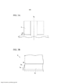
[003] Em um método de produção de uma chapa de aço elétrica com grão orientado, uma chapa de aço laminada a frio é enrolada em uma bobina após o recozimento de descarburação, e é submetida a um recozimento final com o propósito de uma recristalização secundária a uma alta temperatura de 1000°C ou mais. No momento do recozimento final, conforme mostrado na figura 1, uma bobina 5 é disposta em um receptor de bobina 8 na cobertura de um forno de recozimento 9 de maneira tal que o eixo 5a da bobina 5 se torne vertical.[003] In a production method of a grain-oriented electric steel sheet, a cold-rolled steel sheet is wound on a coil after decarburizing annealing, and is subjected to final annealing for the purpose of secondary recrystallization at a high temperature of 1000 ° C or more. At the time of final annealing, as shown in figure 1, a
[004] Quando a bobina 5 disposta conforme descrito acima é recozida a altas temperaturas, conforme mostrado na figura 2A, em uma porção de extremidade inferior 5z da bobina 5 trazida ao contato com o receptor de bobina 8, uma distorção de cambagem chamada tensão lateral é causada pelo peso da bobina 5, pela diferença entre as expansões térmicas da bobina 5 e do receptor de bobinas 8 ou similares.[004] When the
[005] Conforme mostrado na figura 2B, a tensão lateral é observada como uma altura h de uma onda quando a chapa de aço desenrolada da bobina é disposta em uma superfície plana. Em geral, a porção de tensão lateral 5e é a região deformada da porção da extremidade da chapa de aço, que satisfaz a condição em que a altura h da onda excede 2 mm ou a condição em que a declividade s expressa pela Equação (1) a seguir excede 1,5% (excede 0,015). A porção de tensão lateral 5e não pode ser usada como um produto, uma vez que é aparada por um cortador redondo ou similar quando a bobina é desenrolada após o recozimento final. Portanto, à medida que a porção de tensão lateral 5e aumenta, a largura de aparamento aumenta, enquanto há um problema pelo fato de que o rendimento diminui. S = h/l ... (1)[005] As shown in figure 2B, the lateral tension is observed as a height h of a wave when the steel sheet unwound from the coil is laid out on a flat surface. In general, the
[006] Aqui, l indica a largura da porção de tensão lateral.[006] Here, l indicates the width of the lateral tension portion.
[007] Um mecanismo de geração da tensão lateral no momento do recozimento final é explicado por um deslizamento nos contornos de grão a altas temperaturas. Especificamente, a uma alta temperatura de 900°C ou mais, a tensão lateral provocada pelo desl izamento dos contornos de grão se torna notável, de forma que na porção dos contornos de grão, a tensão lateral é apta a ocorrer. Um período crescente de uma recristalização secundária na porção de extremidade inferior da bobina, que é trazida ao contato com o receptor de bobina, é mais lento que na porção central da bobina. Portanto, na porção da extremidade inferior da bobina, o tamanho de grão se torna pequeno e, portanto uma porção de grão refinado é apta a ser formada.[007] A mechanism for generating lateral tension at the time of final annealing is explained by a slip in the grain boundaries at high temperatures. Specifically, at a high temperature of 900 ° C or more, the lateral tension caused by the sliding of the grain contours becomes noticeable, so that in the portion of the grain contours, the lateral tension is apt to occur. An increasing period of secondary recrystallization in the lower end portion of the coil, which is brought into contact with the coil receiver, is slower than in the central portion of the coil. Therefore, in the lower end portion of the coil, the grain size becomes small and therefore a refined grain portion is able to be formed.
[008] Presume-se que uma vez que, muitas bordas de grãos de cristal estão presentes na porção de grão refinado, o deslizamento nos contornos de grão ocorre facilmente e, portanto ocorre a tensão lateral. Consequentemente, na técnica convencional, vários métodos foram sugeridos para suprimir a deformação mecânica pelo controle do crescimento do grão de cristal na porção da extremidade inferior da bobina.[008] It is assumed that since many edges of crystal grains are present in the refined grain portion, sliding in the grain contours occurs easily and, therefore, lateral tension occurs. Consequently, in the conventional technique, several methods have been suggested to suppress mechanical deformation by controlling the growth of the crystal grain in the lower end portion of the coil.
[009] Na Citação da Patente 1, é descrito um método onde antes do recozimento final, é aplicado um refinador de grão em uma porção em forma de tira tendo uma largura predeterminada a partir da face da extremidade inferior da bobina que é trazida ao contato com o receptor de bobina e grãos na porção em forma de tira são refinados durante o recozimento final. Em adição, na Citação da Patente 2, é descrito um método onde antes do recozimento final, uma tensão (deformação) é aplicada à porção em forma de tira tendo uma largura predeterminada a partir da face da extremidade inferior da bobina que é trazida ao contato com o receptor de bobina por um cilindro ou similar no qual são formados saliências, e os grãos na porção em forma de tiras são refinados durante o recozimento final.[009] In
[0010] Conforme descrito acima, nos métodos descritos na Citação da Patente 1 e na Citação da Patente 2, para suprimir a tensão lateral, os grãos de cristal na porção da extremidade inferior da bobina são intencionalmente refinados e portanto a resistência mecânica na porção da extremidade inferior da bobina é mudada.[0010] As described above, in the methods described in Patent
[0011] Entretanto, no método em que o refinador de grão é aplicado, que está descrito na Citação da Patente 1, uma vez que o refinador de grão está na forma de líquido, é difícil controlar com precisão a região de aplicação. Em adição, o refinador de grão pode ser difundido a partir da porção da extremidade da chapa de aço na direção da porção central da chapa de aço. Portanto, é difícil controlar a largura da região de refino do grão, de forma que a largura da porção de tensão lateral pode variar grandemente na direção longitudinal da bobina.[0011] However, in the method in which the grain refiner is applied, which is described in
[0012] A largura da porção de tensão lateral, que é a mais deformada, é ajustada como a largura de aparamento, de modo que mesmo quando a largura da porção de tensão lateral é grande em apenas um lugar, a largura de aparamento aumenta e, portanto orendimento é reduzido.[0012] The width of the lateral tension portion, which is the most deformed, is adjusted as the trimming width, so that even when the width of the lateral tension portion is large in just one place, the trimming width increases and , so budget is reduced.
[0013] Em adição, no método em que a tensão é aplicada, que está descrito na Citação da Patente 2, os grãos de cristal na porção da extremidade inferior da bobina são refinados usando-se a tensão provocada através de um trabalho mecânico pelo cilindro ou similar como ponto de partida. Nesse método, a região de refino do grão pode ser relativamente bem controlada. Entretanto, há o problema de que uma vez que o cilindro é desgastado devido ao trabalho contínuo por um período estendido de tempo, a quantidade de tensão (razão de redução) aplicada diminui com a passagem do tempo e, portanto o efeito do refino do grão diminui. Particularmente, a chapa de aço elétrico com grão orientado é um material duro contendo uma grande quantidade de Si, de modo que a abrasão no cilindro é severa, e portanto é necessário substituir frequentemente o cilindro.[0013] In addition, in the method in which tension is applied, which is described in
[0014] Por outro lado, nas Citações da Patente 3 a 6, é descrito um método onde, para suprimir a tensão lateral, é desenvolvida a recristalização secundária na porção em forma de tira tendo uma largura predeterminada a partir da face da extremidade inferior da bobina, o tamanho de grão é feito aumentar rapidamente durante o recozimento final, e assim a resistência à alta temperatura é aumentada.[0014] On the other hand, in
[0015] Como meio para tornar o tamanho de grão grande, as Citações da Patente 3 e 4 descrevem um método onde a porção em forma de tira da porção de extremidade da chapa de aço é aquecida por aquecimento a plasma ou aquecimento por indução antes do recozimento final. Em adição, nas Citações da Patente 3.5 e 6 é descrito um método em que a tensão é introduzida por um trabalho mecânico usando-se um jateamento, um cilindro, denteado ou similares.[0015] As a means of making the grain size large,
[0016] O aquecimento a plasma e o aquecimento por indução são métodos de aquecimento nos quais a faixa de aquecimento é relativamente ampla, de forma que eles sejam adequados para aquecer a faixa em forma de tira. Entretanto, há um problema pelo fato de que no aquecimento a plasma e no aquecimento por indução é difícil controlar a posição de aquecimento e a temperatura de aquecimento. Em adição, há um problema pelo fato de que uma região mais ampla que a faixa predeterminada é aquecida devido à condução do aquecimento. Portanto, é difícil controlar constantemente a largura da região onde o tamanho de grão aumenta pela recristalização secundária, de modo que há o problema de que pode ocorrer facilmente não uniformidade no efeito de supressão da tensão lateral.[0016] Plasma heating and induction heating are heating methods in which the heating range is relatively wide, so that they are suitable for heating the strip-shaped strip. However, there is a problem with the fact that in plasma heating and induction heating it is difficult to control the heating position and the heating temperature. In addition, there is a problem with the fact that a region wider than the predetermined range is heated due to the conduction of heating. Therefore, it is difficult to constantly control the width of the region where the grain size increases by secondary recrystallization, so there is a problem that non-uniformity in the side tension suppression effect can easily occur.
[0017] No método executado por um trabalho mecânico usando o cilindro ou similar, conforme descrito acima, há um problema pelo fato de que o efeito de aplicação da tensão (quantidade de tensão) é diminuído, com a passar do tempo, devido à abrasão do cilindro. Especificamente, a taxa da recristalização secundária varia significativamente dependendo da quantidade de tensão, de forma que há o problema pelo fato de que é difícil obter um tamanho de grão predeterminado para obter estavelmente o efeito de supressão da tensão lateral mesmo quando a quantidade de tensão devido à abrasão do cilindro é pequena.[0017] In the method performed by a mechanical work using the cylinder or similar, as described above, there is a problem due to the fact that the effect of applying the tension (amount of tension) is diminished, over time, due to abrasion the cylinder. Specifically, the rate of secondary recrystallization varies significantly depending on the amount of stress, so there is a problem with the fact that it is difficult to obtain a predetermined grain size to stably obtain the lateral stress suppression effect even when the amount of stress due abrasion of the cylinder is small.
[0018] Citação da Patente 1 Pedido da Patente Japonesa não examinada, primeira publicação n° S63-100131[0018]
[0019] Citação da Patente 2 Pedido da Patente Japonesa não examinada, primeira publicação n° S64-042530[0019]
[0020] Citação da Patente 3 Pedido da Patente Japonesa não examinada, primeira publicação n° H02-097622[0020]
[0021] Citação de Patente 4 Pedido da Patente Japonesa não examinada, primeira publicação n° H03-177518[0021] Patent Citation 4 Japanese Patent Application not examined, first publication no. H03-177518
[0022] Citação de Patente 5 Pedido da Patente Japonesa não examinada, primeira publicação n° 2000-038616[0022]
[0023] Citação de Patente 6 Pedido da Patente Japonesa não examinada, primeira publicação n° 2001-323322[0023] Patent Citation 6 Japanese Patent Application not examined, first publication n ° 2001-323322
[0024] Conforme descrito acima, na técnica convencional, há o problema de que uma vez uma vez que é difícil executar com precisão o controle (faixa e tamanho) do grão de cristal, é difícil obter um efeito suficiente de supressão da tensão lateral.[0024] As described above, in the conventional technique, there is the problem that since it is difficult to carry out the control accurately (range and size) of the crystal grain, it is difficult to obtain a sufficient effect of suppression of the lateral tension.
[0025] Um objetivo da presente invenção é resolver o problema descrito acima na técnica convencional, e suprimir a tensão lateral na porção da extremidade inferior da bobina que é trazida ao contato com o receptor de bobina dentro do forno de recozimento final, que é provocada pelo deslizamento a alta temperatura no recozimento final.[0025] An objective of the present invention is to solve the problem described above in the conventional technique, and to suppress the lateral tension in the portion of the lower end of the coil that is brought into contact with the coil receiver inside the final annealing furnace, which is caused by sliding at high temperature in the final annealing.
[0026] Isto é, na presente invenção, é possível fornecer um método de produção de uma chapa de aço elétrica com grão orientado onde a supressão de uma tensão lateral pode ser estavelmente e eficientemente executada e a largura da porção de tensão lateral pode ser limitada a estar dentro da faixa predeterminada.[0026] That is, in the present invention, it is possible to provide a method of producing an electrical steel sheet with oriented grain where the suppression of a lateral tension can be stably and efficiently performed and the width of the lateral tension portion can be limited to be within the predetermined range.
[0027] Os inventores estudaram intensivamente métodos para resolver os problemas acima descritos. Como resultado, eles descobriram que quando uma porção preferencialmente deformável é formada para ter uma distância constante de uma extremidade da face da chapa de aço, em uma única face ou em ambas as faces de uma região da extremidade (primeira porção de extremidade) em um lado de uma chapa de aço antes do recozimento final, a largura da porção de tensão lateral em um lado de uma chapa de aço antes do recozimento final, a largura da porção de tensão lateral pode ser limitada a estar dentro de uma faixa predeterminada. Em adição, a porção preferencialmente deformável não é formada na região da extremidade (segunda porção de extremidade) no outro lado da chapa de aço.[0027] The inventors have intensively studied methods to solve the problems described above. As a result, they found that when a preferably deformable portion is formed to have a constant distance from one end of the steel sheet face, on a single face, or on both faces of an end region (first end portion) in one side of a steel sheet before final annealing, the width of the side tension portion on one side of a steel sheet before final annealing, the width of the side tension portion can be limited to be within a predetermined range. In addition, the preferably deformable portion is not formed in the end region (second end portion) on the other side of the steel sheet.
[0028] A presente invenção foi feita com base na descoberta acima, e o resumo da presente invenção é como segue.[0028] The present invention was made on the basis of the above discovery, and the summary of the present invention is as follows.
[0029] Um método de produção de chapa de aço elétrica com grão orientado inclui formar uma porção preferencialmente deformável na região da extremidade de uma chapa de aço de modo a ser paralela à direção de laminação da chapa de aço; bobinar a chapa de aço; e executar um recozimento final na chapa de aço após dispor a chapa de aço de uma maneira tal que a região extrema se torne o lado inferior da chapa de aço.[0029] A method of producing electric steel sheet with oriented grain includes forming a preferably deformable portion in the end region of a steel sheet so as to be parallel to the rolling direction of the steel sheet; winding the steel sheet; and carrying out a final annealing on the steel sheet after arranging the steel sheet in such a way that the extreme region becomes the underside of the steel sheet.
[0030] No método de produção de uma chapa de aço elétrico com grão orientado conforme o item (1), a porção preferencialmente deformável pode ser formada continuamente.[0030] In the production method of an electric steel sheet with grain oriented according to item (1), the preferably deformable portion can be formed continuously.
[0031] No método de produção de uma chapa de aço elétrica com grão orientado conforme o item (1), a porção preferencialmente deformável pode ser formada descontinuamente.[0031] In the production method of an electric steel sheet with grain oriented according to item (1), the preferably deformable portion can be formed discontinuously.
[0032] No método de produção de uma chapa de aço elétrica com grão orientado conforme o item (1), a porção preferencialmente deformável pode ser formada por todo o comprimento da chapa de aço.[0032] In the production method of an electric steel sheet with grain oriented according to item (1), the preferably deformable portion can be formed along the entire length of the steel sheet.
[0033] No método de produção de uma chapa de aço elétrica com grão orientado conforme o item (1), a porção preferencialmente deformável pode ser formada na parte da chapa de aço na direção de laminação.[0033] In the production method of an electric steel sheet with grain oriented according to item (1), the preferably deformable portion can be formed in the part of the steel sheet in the rolling direction.
[0034] No método de produção de uma chapa de aço elétrica com grão orientado conforme o item (1), a porção preferencialmente deformável pode ser formada a uma distância de 5 a 100 mm a partir da face da extremidade inferior.[0034] In the production method of an electric steel sheet with grain oriented according to item (1), the preferably deformable portion can be formed at a distance of 5 to 100 mm from the face of the lower end.
[0035] No método de produção de uma chapa de aço elétrica com grão orientado conforme o item (1), quando o recozimento final é executado, a chapa de aço pode ser disposta de maneira tal que a direção do eixo da bobina da chapa de aço após ser enrolada na forma de bobina se torne perpendicular ao receptor de bobina.[0035] In the production method of an electric steel sheet with grain oriented according to item (1), when the final annealing is performed, the steel sheet can be arranged in such a way that the direction of the coil axis of the steel sheet steel after being wound in the form of a coil becomes perpendicular to the coil receiver.
[0036] No método de produção de uma chapa de aço elétrica com grão orientado conforme o item (1), a porção preferencialmente deformável pode ser formada antes de um recozimento separador ser aplicado na chapa de aço.[0036] In the production method of an electric steel sheet with grain oriented according to item (1), the preferably deformable portion can be formed before a separating annealing is applied to the steel sheet.
[0037] No método de produção de uma chapa de aço elétrica com grão orientado conforme o item (1), a porção preferencialmente deformável pode ser formada pela irradiação de um raio laser.[0037] In the production method of an electric steel sheet with grain oriented according to item (1), the preferably deformable portion can be formed by the irradiation of a laser beam.
[0038] No método de produção de uma chapa de aço elétrica com grão orientado conforme o item (1), um sulco pode ser formado na porção preferencialmente deformável.[0038] In the production method of an electric steel sheet with grain oriented according to item (1), a groove can be formed in the preferably deformable portion.
[0039] No método de produção de uma chapa de aço elétrica com grão orientado conforme o item (10), o sulco pode ser formado em uma face única da chapa de aço.[0039] In the production method of an electric steel sheet with grain oriented according to item (10), the groove can be formed on a single face of the steel sheet.
[0040] No método de produção de uma chapa de aço elétrica com grão orientado conforme o item (10), o sulco pode ser formado em ambas as faces da chapa de aço.[0040] In the production method of an electric steel sheet with grain oriented according to item (10), the groove can be formed on both sides of the steel sheet.
[0041] No método de produção de uma chapa de aço elétrica com grão orientado conforme o item (10), a largura do sulco pode ser de 0,03 a 10 mm.[0041] In the production method of an electric steel sheet with grain oriented according to item (10), the groove width can be from 0.03 to 10 mm.
[0042] No método de produção de uma chapa de aço elétrica com grão orientado conforme o item (10), a profundidade d do sulco e a espessura t da chapa de aço devem satisfazer a equação 0,05 < d/t < 0,7.[0042] In the production method of an electric steel sheet with grain oriented according to item (10), the depth d of the groove and the thickness t of the steel sheet must satisfy the equation 0.05 <d / t <0, 7.
[0043] No método de produção de uma chapa de aço elétrica com grão orientado conforme o item (1), a porção preferencialmente deformável pode ser uma porção deslizante do contorno de grão.[0043] In the production method of an electric steel sheet with grain oriented according to item (1), the preferably deformable portion can be a sliding portion of the grain contour.
[0044] No método de produção de uma chapa de aço elétrica com grão orientado conforme o item (15), a porção deslizante do contorno de grão após o recozimento final pode ser uma borda de grão de cristal linear.[0044] In the production method of an electric steel sheet with grain oriented according to item (15), the sliding portion of the grain contour after the final annealing can be a linear crystal grain edge.
[0045] No método de produção de uma chapa de aço elétrica com grão orientado conforme o item (15), a porção deslizante do contorno de grão após o recozimento final pode ser uma tira deslizante incluindo grãos de cristal.[0045] In the method of producing an electric steel sheet with grain oriented according to item (15), the sliding portion of the grain contour after the final annealing can be a sliding strip including crystal grains.
[0046] No método de produção de uma chapa de aço elétrica com grão orientado conforme o item (17), a largura da tira deslizante pode ser de 0,02 a 20 mm.[0046] In the production method of an electric steel sheet with grain oriented according to item (17), the width of the sliding strip can be from 0.02 to 20 mm.
[0047] Em uma chapa de aço elétrica com grão orientado, a porção termicamente deformada é formada na região de extremidade de uma chapa de aço de modo a ser paralela à direção de laminação da chapa de aço.[0047] In an electric steel sheet with oriented grain, the thermally deformed portion is formed in the end region of a steel sheet so as to be parallel to the rolling direction of the steel sheet.
[0048] Na chapa de aço elétrica com grão orientado conforme o item (19), a porção termicamente deformada pode ser formada continuamente.[0048] In the electric steel plate with grain oriented according to item (19), the thermally deformed portion can be formed continuously.
[0049] Na chapa de aço elétrica com grão orientado conforme o item (19), a porção termicamente deformada pode ser formada descontinuamente.[0049] In the electric steel plate with grain oriented according to item (19), the thermally deformed portion can be formed discontinuously.
[0050] Na chapa de aço elétrica com grão orientado conforme o item (19), a porção termicamente deformada pode ser formada por todo o comprimento da chapa de aço.[0050] In the electric steel sheet with grain oriented according to item (19), the thermally deformed portion can be formed along the entire length of the steel sheet.
[0051] Na chapa de aço elétrica com grão orientado conforme o item (19), a porção termicamente deformada pode ser formada em uma parte da chapa de aço na direção de laminação.[0051] In the electric steel sheet with grain oriented according to item (19), the thermally deformed portion can be formed in a part of the steel sheet in the rolling direction.
[0052] Na chapa de aço elétrica com grão orientado conforme o item (19), a porção termicamente deformada pode ser formada a uma distância de 5 a 100 mm da extremidade da face da região de extremidade.[0052] In the electric steel plate with grain oriented according to item (19), the thermally deformed portion can be formed at a distance of 5 to 100 mm from the end of the face of the end region.
[0053] Na chapa de aço elétrica com grão orientado conforme o item (19), a porção termicamente deformada pode ser um sulco.[0053] In the electric steel sheet with grain oriented according to item (19), the thermally deformed portion can be a groove.
[0054] Na chapa de aço elétrica com grão orientado conforme o item (25), o sulco pode ser formado em uma face única da chapa de aço.[0054] In the electric steel sheet with grain oriented according to item (25), the groove can be formed on a single face of the steel sheet.
[0055] Na chapa de aço elétrica com grão orientado conforme o item (25), o sulco pode ser formado em ambas as faces da chapa de aço.[0055] In the electric steel sheet with grain oriented according to item (25), the groove can be formed on both sides of the steel sheet.
[0056] Na chapa de aço elétrica com grão orientado conforme o item (25), a largura do sulco pode ser de 0,03 a 10 mm.[0056] In the electric steel sheet with grain oriented according to item (25), the width of the groove can be from 0.03 to 10 mm.
[0057] Na chapa de aço elétrica com grão orientado conforme o item (25), a profundidade d do sulco e a espessura t da chapa de aço devem satisfazer a equação 0,05< d/t < 0,7.[0057] In the electric steel plate with grain oriented according to item (25), the depth d of the groove and the thickness t of the steel plate must satisfy the equation 0.05 <d / t <0.7.
[0058] Na chapa de aço elétrica com grão orientado conforme o item (19), a porção termicamente deformada pode ser uma borda de grão de cristal linear.[0058] In the electric steel sheet with grain oriented according to item (19), the thermally deformed portion can be a linear crystal grain edge.
[0059] Na chapa de aço elétrica com grão orientado conforme o item (19), a porção termicamente deformada pode ser uma tira deslizante incluindo grãos de cristal.[0059] In the electric steel plate with grain oriented according to item (19), the thermally deformed portion can be a sliding strip including crystal grains.
[0060] Na chapa de aço elétrica com grão orientado conforme o item (31), a largura da tira deslizante pode ser de 0,02 a 20 mm.[0060] In the electric steel sheet with grain oriented according to item (31), the width of the sliding strip can be from 0.02 to 20 mm.
[0061] De acordo com apresente invenção, durante o recozimento final, a porção preferivelmente deformável que é formada na porção da extremidade inferior da bobina é preferencialmente deformada e a tensão lateral que se desenvolve a partir da face da extremidade inferior da bobina é limitada pela porção preferencialmente deformável, de forma que a largura da porção de tensão lateral se torna um valor substancialmente constante. Portanto, a largura de aparamento em um processamento posterior pode ser reduzida tanto quanto possível, e assim o rendimento é melhorado.[0061] According to the present invention, during the final annealing, the preferably deformable portion that is formed in the lower end portion of the coil is preferably deformed and the lateral tension that develops from the face of the lower end of the coil is limited by preferably deformable portion, so that the width of the lateral tension portion becomes a substantially constant value. Therefore, the trimming width in further processing can be reduced as much as possible, and thus the throughput is improved.
[0062] Em adição, de acordo com a presente invenção, é possível formar uma porção preferencialmente deformável de forma que um sulco e uma porção deslizante do contorno de grão a uma alta velocidade e com um padrão livre usando um raio laser. Além disso, é possível executar um trabalho usando-se o raio laser sem contatar a chapa de aço, de forma que não ocorra o problema provocado pela abrasão (degradação com o tempo) em um equipamento de trabalho (ferramenta de trabalho) tal como um cilindro que é usado em um trabalho mecânico. Isto é, a quantidade de trabalho não varia com a passagem de tempo, de forma que não é necessário substituir o equipamento de trabalho. Além disso, é possível formar estavelmente a porção preferencialmente deformável que é ótima para suprimir a tensão lateral em uma linha de produção de uma chapa de aço elétrica com grão orientado pelo controle da densidade de energia de irradiação e do diâmetro do raio de laser.[0062] In addition, according to the present invention, it is possible to form a preferably deformable portion such that a groove and a sliding portion of the grain contour at a high speed and with a free pattern using a laser beam. In addition, it is possible to perform a job using the laser beam without contacting the steel plate, so that the problem caused by abrasion (degradation with time) in a work equipment (work tool) such as a cylinder that is used in mechanical work. That is, the amount of work does not vary with the passage of time, so there is no need to replace the work equipment. In addition, it is possible to stably form the preferably deformable portion which is optimal for suppressing lateral tension in a production line of an electric steel sheet with grain oriented by controlling the radiation energy density and the diameter of the laser beam.
[0063] A figura 1 é um diagrama ilustrando um exemplo de um equipamento de recozimento final.[0063] Figure 1 is a diagram illustrating an example of a final annealing equipment.
[0064] A figura 2A é um diagrama esquemático ilustrando um processo de crescimento de uma tensão lateral em um caso em que a porção preferencialmente deformável não é formada.[0064] Figure 2A is a schematic diagram illustrating a process of growth of a lateral tension in a case where the preferably deformable portion is not formed.
[0065] A figura 2B é um diagrama ilustrando um exemplo de um método de avaliação de uma tensão lateral da presente invenção.[0065] Figure 2B is a diagram illustrating an example of a method of evaluating a lateral tension of the present invention.
[0066] A figura 3A é um diagrama explicativo ilustrando uma posição da porção preferencialmente deformável.[0066] Figure 3A is an explanatory diagram illustrating a position of the preferably deformable portion.
[0067] A figura 3B é um diagrama esquemático ilustrando um processo de crescimento de uma tensão lateral durante o recozimento final em um caso em que a porção preferencialmente deformável é formada.[0067] Figure 3B is a schematic diagram illustrating a process of growth of a lateral tension during the final annealing in a case in which the preferably deformable portion is formed.
[0068] A figura 4 é um diagrama ilustrando um exemplo de uma forma condensada de raio laser.[0068] Figure 4 is a diagram illustrating an example of a condensed form of laser beam.
[0069] A figura 5 é um diagrama ilustrando esquematicamente um exemplo de uma primeira configuração da presente invenção.[0069] Figure 5 is a diagram illustrating schematically an example of a first configuration of the present invention.
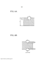
[0070] A figura 6A é um diagrama ilustrando esquematicamente a forma da seção transversal de um sulco formado em uma única face de uma região extrema de uma chapa de aço.[0070] Figure 6A is a diagram schematically illustrating the shape of the cross section of a groove formed on a single face of an extreme region of a steel plate.
[0071] A figura 6B é um diagrama ilustrando esquematicamente a forma da seção transversal dos sulcos formados em ambas as faces de uma região extrema de uma chapa de aço.[0071] Figure 6B is a diagram illustrating schematically the shape of the cross section of the grooves formed on both sides of an extreme region of a steel plate.
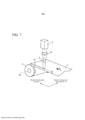
[0072] A figura 7 é um diagrama ilustrando esquematicamente um exemplo de uma segunda configuração da presente invenção.[0072] Figure 7 is a diagram schematically illustrating an example of a second configuration of the present invention.
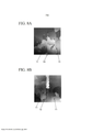
[0073] A figura 8A é uma imagem de uma estrutura metalográfica que é adjacente à porção deslizante do contorno de grão submetida a uma irradiação laser executada de acordo com a segunda configuração.[0073] Figure 8A is an image of a metallographic structure that is adjacent to the sliding portion of the grain contour subjected to laser irradiation performed according to the second configuration.
[0074] A figura 8B é uma imagem de uma estrutura metalográfica que é adjacente à porção deslizante do contorno de grão submetida a uma irradiação laser executada de acordo com um exemplo modificado da segunda configuração.[0074] Figure 8B is an image of a metallographic structure that is adjacent to the sliding portion of the grain contour subjected to laser irradiation performed according to a modified example of the second configuration.
[0075] A figura 8C é uma imagem de uma estrutura metalográfica à qual uma irradiação laser não é executada.[0075] Figure 8C is an image of a metallographic structure to which a laser irradiation is not performed.
[0076] Doravante configurações exemplares da presente invenção serão descritas em detalhes em relação aos desenhos anexos.Além disso, nessa especificação e nos desenhos anexos, serão dados símbolos de referência iguais a componentes iguais que tenham substancialmente as mesmas funções, e sua descrição redundante será omitida.[0076] Hereinafter exemplary configurations of the present invention will be described in detail in relation to the attached drawings. In addition, in this specification and in the attached drawings, reference symbols equal to equal components that have substantially the same functions will be given, and their redundant description will be omitted.
[0077] Na presente invenção, conforme mostrado na figura 3A, em uma posição em uma bobina que seja espaçada a uma distância predeterminada de uma posição de contato de uma bobina 5 e de um receptor de bobina 8, uma porção preferencialmente deformável 5f tendo uma resistência mecânica fraca é formada ao longo da direção de laminação da bobina 5 (direção de laminação da chapa de aço). Em um caso em que a carga é aplicada à bobina 5 em um forno de recozimento a alta temperatura, a porção preferencialmente deformável 5f é inicialmente deformada por cambagem ou deslizamento (escorregamento), a carga aplicada a uma porção localizada na direção superior da porção preferencialmente deformável 5f é dispersa e, portanto o aumento e a variação da largura da porção de tensão lateral são suprimidos. Em adição, a porção de tensão lateral é uma região de deformação da porção de extremidade da chapa de aço, que satisfaz a condição em que a altura n de uma onda excede 2 mm ou uma condição em que a inclinação s expressa pela Equação (1) acima excede 1,5% (excede 0,015).[0077] In the present invention, as shown in figure 3A, in a position on a coil that is spaced at a predetermined distance from a contact position of a
[0078] A seguir será descrito em detalhes um efeito da porção preferencialmente deformável 5f em um método de produção de chapa de aço elétrica com grão orientado da presente invenção usando-se as figuras.2A e 3B. A figura 2A mostra um diagrama esquemático ilustrando um processo de crescimento da porção de tensão lateral 5e durante o recozimento final em um caso em que a porção preferencialmente deformável 5f conforme a presente invenção não é formada. A figura 3B mostra um diagrama esquemático ilustrando um processo de crescimento da porção de tensão lateral 5e durante o recozimento final em um caso em que a porção preferencialmente deformável 5f conforme a presente invenção é formada. Em adição, nas figuras. 2A e 3B, a linha sólida mostra um diagrama esquemático no qual a porção da extremidade inferior da bobina no momento do recozimento final é aumentada, a linha pontilhada mostra um diagrama esquemático no qual a porção da extremidade inferior da bobina após o recozimento final é aumentada, e a linha quebrada mostra um diagrama esquemático no qual a porção da extremidade inferior da bobina antes do recozimento final é aumentada. Conforme mostrado na figura 2A, se a porção preferencialmente deformável 5f não for formada na bobina 5, uma porção de tensão lateral 5e progride a partir da face da extremidade inferior 5 na direção de um lado superior com a passagem de um tempo de recozimento (compare entre a posição da extremidade superior da porção de tensão lateral 5e na linha sólida e a porção da extremidade superior da porção de tensão lateral 5e na linha pontilhada). A largura (comprimento na direção vertical) da porção de tensão lateral 5e é aumentada de acordo com o tempo de recozimento, e varia na direção longitudinal (direção de laminação) da bobina 5 devido à não uniformidade na resistência da bobina 5 a altas temperaturas (recristalização secundária).[0078] In the following, an effect of the preferably
[0079] Entretanto, conforme mostrado na figura 3B, quando a porção preferencialmente deformável 5f é formada na bobina 5, a porção preferencialmente deformável 5f é preferencialmente deformada, Portanto, a porção de tensão lateral 5e não progride a partir da porção preferencialmente deformável 5f na direção do lado superior com a passagem do tempo de recozimento (compare entre a posição da extremidade superior da porção de tensão lateral 5e na linha sólida a posição da extremidade superior da porção de tensão lateral 5e na linha pontilhada). Consequentemente, a largura da porção de tensão lateral 5e não depende do tempo de recozimento, e é determinada pela posição da porção preferencialmente deformável 5f. Além disso, mesmo para a não uniformidade da resistência da bobina 5 a altas temperaturas (recristalização secundária) a largura da porção de tensão lateral 5e não varia na direção longitudinal (direção de laminação) da bobina 5.[0079] However, as shown in figure 3B, when the preferably
[0080] Conforme descrito acima, na presente invenção, a porção preferencialmente deformável é formada na região de extremidade (porção de extremidade inferior da bobina) da chapa de aço de modo a ser paralela à direção de laminação da chapa de aço, de forma que a largura da porção de tensão lateral seja limitada e, portanto seja possível melhorar o rendimento da chapa de aço elétrica com grão orientado.[0080] As described above, in the present invention, the preferably deformable portion is formed in the end region (lower end portion of the coil) of the steel sheet so as to be parallel to the rolling direction of the steel sheet, so that the width of the lateral tension portion is limited and, therefore, it is possible to improve the performance of the electric steel sheet with oriented grain.
[0081] Em adição, um exemplo específico da porção preferencialmente deformável da presente invenção será descrita. É necessário que a resistência mecânica da porção preferencialmente deformável no momento do recozimento final seja feita para ser suficientemente pequena de forma que a porção preferencialmente deformável mostra o efeito descrito acima. Na presente invenção, a porção preferencialmente deformável é, por exemplo, uma porção de sulco tendo um sulco ou uma porção deslizante do contorno de grão descrita mais tarde. Em um caso em que a porção preferencialmente deformável é a porção de sulco, quando a resistência da bobina diminui a altas temperaturas, a tensão é concentrada na porção de sulco e, portanto a porção de sulco é preferencialmente deformada. Em adição, quando a porção preferencialmente deformável é a porção deslizante do contorno de grão (porção deslizável do contorno de grão), a porção deslizante do contorno de grão preferencialmente provoca um deslizamento à alta temperatura (deformação).[0081] In addition, a specific example of the preferably deformable portion of the present invention will be described. It is necessary that the mechanical strength of the preferably deformable portion at the time of final annealing be made to be sufficiently small so that the preferably deformable portion shows the effect described above. In the present invention, the preferably deformable portion is, for example, a groove portion having a groove or a sliding portion of the grain outline described later. In a case where the preferably deformable portion is the groove portion, when the coil resistance decreases at high temperatures, the stress is concentrated on the groove portion and, therefore, the groove portion is preferably deformed. In addition, when the preferably deformable portion is the sliding portion of the grain contour (sliding portion of the grain contour), the sliding portion of the grain contour preferably causes sliding at high temperature (deformation).
[0082] É necessário que a porção preferencialmente deformável seja formada com precisão dentro de uma faixa estreita predeterminada para ser paralela a uma face de extremidade da chapa de aço de forma que a porção preferencialmente deformável é preferencialmente deformada. Portanto, é preferível que como um equipamento de trabalho capaz de condensar uma seção a ser trabalhada (por exemplo, uma seção de irradiação de laser) para formar a porção preferencialmente deformável, por exemplo, um equipamento de laser é usado. Quando a porção preferencialmente deformável é formada usando-se o equipamento a laser, a largura da porção preferencialmente deformável pode ser controlada dentro de uma faixa estreita predeterminada pelo ajuste do diâmetro de condensação do raio laser. Conforme mostrado na figura 4, a forma condensada do raio laser é uma forma elíptica que tem um diâmetro dc na direção da largura da chapa (direção C) e um diâmetro dL na direção de laminação (direção L).[0082] It is necessary that the preferably deformable portion be precisely formed within a predetermined narrow band to be parallel to an end face of the steel sheet so that the preferably deformable portion is preferably deformed. Therefore, it is preferable that as a work equipment capable of condensing a section to be worked (for example, a laser irradiation section) to form the preferably deformable portion, for example, a laser equipment is used. When the preferably deformable portion is formed using laser equipment, the width of the preferably deformable portion can be controlled within a narrow range predetermined by adjusting the condensation diameter of the laser beam. As shown in figure 4, the condensed shape of the laser beam is an elliptical shape that has a diameter dc in the direction of the width of the plate (direction C) and a diameter dL in the direction of lamination (direction L).
[0083] Aqui, é necessário que a seção de irradiação a laser seja espaçada a partir da face da extremidade da chapa de aço de modo a satisfazer a Equação (2) a seguir. a > dc/2 ... (2)[0083] Here, it is necessary that the laser irradiation section be spaced from the end face of the steel sheet in order to satisfy Equation (2) below. a> dc / 2 ... (2)
[0084] Em adição, a densidade de energia Ed introduzida à porção preferencialmente deformável usando o equipamento a laser é definido pela Equação (3) usando uma energia laser P (W), o diâmetro dc (mm) na direção da largura da chapa (direção C) do raio laser, e a velocidade de alimentação VL (mm/s) de uma chapa de aço. Ed = (4/π)xP/(dcxVL) ... (3)[0084] In addition, the energy density Ed introduced to the preferably deformable portion using the laser equipment is defined by Equation (3) using a laser energy P (W), the diameter dc (mm) in the direction of the plate width ( direction C) of the laser beam, and the feed speed VL (mm / s) of a steel plate. Ed = (4 / π) xP / (dcxVL) ... (3)
[0085] A densidade de energia Ed é controlada conforme o tipo e forma da porção preferencialmente deformável conforme descrito mais tarde.[0085] The energy density Ed is controlled according to the type and shape of the preferably deformable portion as described later.
[0086] Em adição, o tipo de laser não é especificamente limitado enquanto o laser puder formar a porção preferencialmente deformável com uma forma predeterminada na superfície da chapa de aço. Por exemplo, um laser CO2, um laser YAG, um laser semicondutor, um laser de fibra ou similares podem ser usados.[0086] In addition, the type of laser is not specifically limited as long as the laser can form the preferably deformable portion with a predetermined shape on the surface of the steel sheet. For example, a CO2 laser, a YAG laser, a semiconductor laser, a fiber laser or the like can be used.
[0087] Em adição, a porção preferencialmente deformável formada pelo equipamento de trabalho pode ser formada continuamente ou pode ser formada por todo o comprimento da chapa de aço na direção de laminação. Entretanto, para economia de energia, a porção preferencialmente deformável pode ser formada descontinuamente ou pode ser formada em uma parte da chapa de aço na direção de laminação. Por exemplo, quando é usado um raio laser de onda contínua, a porção referencialmente deformável, que é contínua na direção da laminação, é formada. Em adição, por exemplo, quando é usado um laser pulsado, uma porção preferencialmente deformável descontínua (por exemplo, uma porção preferencialmente deformável tendo a forma de uma linha pontilhada) é formada. Pode ser formada uma pluralidade de porções preferencialmente deformáveis de modo a serem paralelas entre si.[0087] In addition, the preferably deformable portion formed by the work equipment can be formed continuously or it can be formed along the entire length of the steel sheet in the rolling direction. However, for energy savings, the preferably deformable portion may be formed discontinuously or may be formed on a portion of the steel sheet in the direction of rolling. For example, when a continuous wave laser beam is used, the referentially deformable portion, which is continuous in the lamination direction, is formed. In addition, for example, when a pulsed laser is used, a preferably discontinuous deformable portion (for example, a preferably deformable portion having the shape of a dotted line) is formed. A plurality of preferably deformable portions can be formed so as to be parallel to each other.
[0088] Doravante, inicialmente, será dada a descrição em relação a um caso em que a porção preferencialmente deformável é uma porção sulco. A figura 5 mostra esquematicamente um exemplo de uma primeira configuração da presente invenção para formar a porção de sulco.[0088] From now on, the description will be given in relation to a case in which the preferably deformable portion is a groove portion. Figure 5 shows schematically an example of a first configuration of the present invention to form the groove portion.
[0089] Na primeira configuração mostrada na figura 5, a posição espaçada com uma distância da face da extremidade na direção da largura da chapa de aço (chapa de aço elétrica com grão orientado) 1 é irradiada com um raio laser 3 que sai de um equipamento a laser 2 e é condensado por uma lente condensadora 2a. Pela irradiação do raio laser 3, a porção irradiada da chapa de aço é fundida ou vaporizada. Além disso, um gás auxiliar altamente pressurizado 7 é injetado por um bocal 6 em relação à porção irradiada para soprar o material fundido remanescente e assim é formada uma porção de sulco 4a tendo um sulco.[0089] In the first configuration shown in figure 5, the position spaced with a distance from the end face in the direction of the width of the steel plate (electric steel plate with oriented grain) 1 is irradiated with a
[0090] A chapa de aço 1 é alimentada na direção L (direção de laminação) a uma velocidade VL, de modo que a porção de sulco 4a seja formada ao longo da direção de laminação da chapa de aço. Após a porção de sulco 4a ser formada na chapa de aço 1, um separador de recozimento é aplicado à superfície da chapa de aço 1, e a chapa de aço 1 é enrolada como uma bobina 5.[0090]
[0091] Conforme mostrado na figura 1, o recozimento final é executado em relação à bobina 5 em um estado em que a porção final (região final), que tem uma porção de sulco 4a, de uma chapa de aço em forma de bobina 1 está voltada para o lado inferior. No recozimento final, é preferível que a chapa de aço em forma de bobina 1 seja posicionada de maneira tal que o eixo da bobina 5a da chapa de aço em forma de bobina (bonina 5) seja vertical em relação ao receptor de bobina 8 dentro de um equipamento de recozimento 9.[0091] As shown in figure 1, the final annealing is performed in relation to the
[0092] Para melhorar o rendimento da chapa de aço elétrica com grão orientado, é preferível que a posição (porção de sulco ou posição de trabalho) seja irradiada com o raio laser, isto é, a distância na qual o sulco deve ser formado é 100 mm ou menos a partir da face final (face final na região final) da chapa de aço. Para também melhorar o rendimento, mais preferivelmente a porção de sulco é formada a uma distância de 30 mm ou menos a partir da face final na região final da chapa de aço. Para otimizar o rendimento, a distância pode ser determinada de acordo com o peso da bobina. Os inventores descobriram que mesmo em um caso de uma bobina em grande escala tendo a maior largura de chapa, quando a porção de sulco é formada em uma posição de até 100 mm a partir da face final da chapa de aço, é possível suprimir o aumento e a variação na largura da porção de tensão lateral em uma operação prática.[0092] To improve the performance of the electric steel sheet with oriented grain, it is preferable that the position (groove portion or working position) is irradiated with the laser beam, that is, the distance at which the groove must be formed is 100 mm or less from the end face (end face in the end region) of the steel sheet. To also improve the performance, more preferably the groove portion is formed at a distance of 30 mm or less from the end face in the end region of the steel sheet. To optimize performance, the distance can be determined according to the weight of the coil. The inventors found that even in a case of a large-scale coil having the largest plate width, when the groove portion is formed in a position of up to 100 mm from the end face of the steel sheet, it is possible to suppress the increase and the variation in the width of the lateral tension portion in a practical operation.
[0093] Em adição, para produzir o efeito da porção de sulco sem o contato entre a porção de sulco e o receptor de bobina, é preferível que a porção de sulco seja formada a uma distância de 5 mm ou mais a partir da face final da região final da chapa de aço. Para também garantir o efeito da porção de sulco, é preferível que a porção de sulco seja formada a uma distância de 10 mm ou mais a partir da face final da região final da chapa de aço.[0093] In addition, to produce the effect of the groove portion without contact between the groove portion and the coil receiver, it is preferable that the groove portion be formed at a distance of 5 mm or more from the end face of the final region of the steel plate. To also ensure the effect of the groove portion, it is preferable that the groove portion is formed at a distance of 10 mm or more from the end face of the end region of the steel sheet.
[0094] As figuras. 6A e 6B mostram esquematicamente uma seção transversal do sulco formado conforme a presente invenção. Na figura 6A, um sulco tendo uma largura de sulco W e uma profundidade de sulco d é formado em uma única face da chapa de aço tendo a espessura t. Na figura 6B, um sulco tendo uma largura de sulco W1 e uma profundidade de sulco d1 e um sulco tendo uma largura de sulco W2 e uma profundidade de sulco d2 (W1 ~ W2, d = di + d2) são formados em ambas as faces da chapa de aço tendo uma espessura t.[0094] The figures. 6A and 6B schematically show a cross section of the groove formed in accordance with the present invention. In figure 6A, a groove having a groove width W and a groove depth d is formed on a single face of the steel sheet having thickness t. In figure 6B, a groove having a groove width W1 and a groove depth d1 and a groove having a groove width W2 and a groove depth d2 (W1 ~ W2, d = di + d2) are formed on both faces of the steel sheet having a thickness t.
[0095] Como método de formação do sulco com uma forma predeterminada em uma única face da chapa de aço mostrado na figura 6A, um equipamento de trabalho tal como o equipamento a laser 2 da figura 5 pode ser usado. Em adição, conforme mostrado na figura 6B, quando sulcos com uma forma predeterminada são formados em ambas as faces em posições substancialmente opostas entre si, a resistência mecânica da porção de sulco também diminui, de forma que o efeito de supressão da tensão lateral é também significativamente obtido.[0095] As a method of forming the groove with a predetermined shape on a single face of the steel sheet shown in figure 6A, a work equipment such as the
[0096] A forma do sulco da porção de sulco com uma baixa resistência mecânica é projetada em consideração à espessura da chapa. Especificamente é preferível que o sulco seja formado de forma que a razão d/t da profundidade d para a espessura da chapa t satisfaça a Equação (4) a seguir: 0,05< d/t < 0,7 ... (4)[0096] The shape of the groove of the groove portion with a low mechanical resistance is designed considering the thickness of the plate. Specifically, it is preferable that the groove is formed in such a way that the ratio d / t of depth d to the thickness of sheet t satisfies Equation (4) below: 0.05 <d / t <0.7 ... (4 )
[0097] Aqui, em um caso de formação de sulco em ambas as faces, conforme mostrado na figura 6B, as profundidades dos sulcos formados na face frontal e na face traseira são ajustadas como d1 e d2, respectivamente, e a profundidade total (d1 + d2) desses sulcos é ajustada como d.[0097] Here, in a case of groove formation on both sides, as shown in figure 6B, the depths of the grooves formed on the front face and the rear face are adjusted as d1 and d2, respectively, and the total depth (d1 + d2) of these grooves is set to d.
[0098] Na presente invenção, mesmo quando a profundidade do sulco formado na face frontal da chapa de aço é relativamente rasa, o sulco tem um efeito na resistência mecânica da porção de sulco da chapa de aço em um processo de recozimento por um período estendido a altas temperaturas. Entretanto, quando d/t é menor que 0,05, mesmo quando o recozimento é executado além de um período estendido a altas temperaturas, a resistência mecânica da porção de sulco não diminui significativamente, de forma que o efeito da supressão da tensão lateral não é obtido. Portanto, para obter confiavelmente o efeito da supressão da tensão lateral, é preferível que d/t seja 0,05 ou mais. Mais preferivelmente, d/t é 0,1 ou mais.[0098] In the present invention, even when the depth of the groove formed on the front face of the steel sheet is relatively shallow, the groove has an effect on the mechanical strength of the groove portion of the steel sheet in an annealing process for an extended period at high temperatures. However, when d / t is less than 0.05, even when annealing is carried out beyond an extended period at high temperatures, the mechanical strength of the groove portion does not significantly decrease, so that the effect of suppressing lateral tension does not is obtained. Therefore, in order to reliably obtain the effect of suppressing lateral tension, it is preferable that d / t is 0.05 or more. More preferably, d / t is 0.1 or more.
[0099] Por outro lado, quando d/t excede 0,7 a resistência mecânica da porção de sulco diminui enormemente. Portanto, quando a chapa de aço é enrolada em forma de bobina, a chapa de aço é grandemente deformada devido à tensão de bobinamento (tensão de enrolamento) e assim o bobinamento se torna difícil.Em alguns casos, ocorre o problema de que a chapa de aço é cortada. Portanto, é preferível que d/t seja 0,7 ou menos. Mais preferivelmente d/t é 0,5 ou menos.[0099] On the other hand, when d / t exceeds 0.7 the mechanical resistance of the groove portion decreases enormously. Therefore, when the steel sheet is wound in the form of a coil, the steel sheet is greatly deformed due to the winding tension (winding tension) and thus winding becomes difficult. In some cases, the problem occurs that the sheet steel is cut. Therefore, it is preferable that d / t is 0.7 or less. Most preferably d / t is 0.5 or less.
[00100] Especificamente, se é usada uma chapa de aço com uma espessura t de 0,1 mm, a 0,5 mm, é preferível que o limite inferior da profundidade d seja 0,005 mm, e mais preferivelmente 0,01 mm. Em adição, é preferível que o limite superior da profundidade d seja 0,35 mm, e mais preferivelmente 0,25 mm.[00100] Specifically, if a steel plate with a thickness t of 0.1 mm, at 0.5 mm is used, it is preferable that the lower limit of depth d is 0.005 mm, and more preferably 0.01 mm. In addition, it is preferable that the upper limit of depth d is 0.35 mm, and more preferably 0.25 mm.
[00101] Em adição, é preferível que a largura do sulco W da porção de sulco seja de 0,03 mm a 10 mm. Quando a largura do sulco W é menor que 0,03 mm, a resistência mecânica na porção do sulco não diminui suficientemente, e o efeito de supressão da tensão lateral não é obtido. Por outro lado, quando a largura do sulco W é maior que 10 mm, a resistência mecânica da porção de sulco diminui enormemente e, portanto o bobinamento se torna difícil.[00101] In addition, it is preferable that the width of the W groove of the groove portion is from 0.03 mm to 10 mm. When the width of the W groove is less than 0.03 mm, the mechanical strength in the groove portion does not decrease sufficiently, and the lateral stress suppression effect is not obtained. On the other hand, when the width of the groove W is greater than 10 mm, the mechanical strength of the groove portion decreases enormously and, therefore, winding becomes difficult.
[00102] Em um caso em que o sulco é formado pela irradiação do raio laser, a largura do sulco pode ser controlada ajustando-se o diâmetro de condensação do raio laser.[00102] In a case where the groove is formed by the irradiation of the laser beam, the width of the groove can be controlled by adjusting the condensation diameter of the laser beam.
[00103] Em adição, a profundidade do sulco pode ser controlada ajustando-se a energia do laser em combinação com a velocidade de alimentação da chapa de aço. Portanto, na presente invenção, quando o raio laser é usado, é possível formar facilmente um sulco, que tenha uma forma adequada para suprimir a tensão lateral, em uma única face ou em ambas as faces da região final (primeira porção final) em um lado da chapa de aço (chapa de aço elétrica com grão orientado) antes do recozimento final.[00103] In addition, the depth of the groove can be controlled by adjusting the laser energy in combination with the feed speed of the steel plate. Therefore, in the present invention, when the laser beam is used, it is possible to easily form a groove, which has a suitable shape to suppress lateral tension, on a single face or on both faces of the final region (first final portion) in one side of the steel sheet (grain-oriented electric steel sheet) before final annealing.
[00104] Em adição, os inventores revisaram a faixa ótima da densidade de energia Ed do equipamento a laser em um caso de formação de uma porção de sulco usando o equipamento a laser. Aqui, a entrada de densidade de energia Ed para a porção de sulco pelo equipamento a laser é definida pela Equação 3 descrita acima.[00104] In addition, the inventors revised the optimal range of Ed energy density of the laser equipment in a case of formation of a groove portion using the laser equipment. Here, the input of energy density Ed to the groove portion by the laser equipment is defined by
[00105] Em relação à densidade de energia Ed, como resultado das experiências até agora, quando Ed é 05 J/mm2 ou mais, a porção de irradiação a laser é fundida e, portanto é possível formar uma porção de sulco com uma profundidade de sulco suficiente. Entretanto, quando a Ed é menor que 0,5 J/mm2, é difícil formar a porção de sulco a ser deformada preferencialmente durante o recozimento final. Por outro lado, quando Ed excede 5,0 J/mm2, a chapa de aço é cortada pela irradiação a laser, e a eficiência de energia diminui enormemente. Portanto, a faixa preferida de Ed é a faixa expressa pela Equação (5). 0,5 J/mm2 < Ed < 5,0 J/mm2 ... (5)[00105] Regarding the energy density Ed, as a result of experiments so far, when Ed is 05 J / mm2 or more, the laser irradiation portion is fused and therefore it is possible to form a groove portion with a depth of enough groove. However, when the Ed is less than 0.5 J / mm2, it is difficult to form the groove portion to be deformed preferably during the final annealing. On the other hand, when Ed exceeds 5.0 J / mm2, the steel sheet is cut by laser irradiation, and energy efficiency decreases enormously. Therefore, Ed's preferred range is the range expressed by Equation (5). 0.5 J / mm2 <Ed <5.0 J / mm2 ... (5)
[00106] A densidade de energia Ed é controlada para satisfazer a Equação (5) por ajustar adequadamente a energia laser P, o diâmetro dc na direção da largura da chapa (direção C) do raio laser e a velocidade de alimentação VL da chapa de aço.[00106] The energy density Ed is controlled to satisfy Equation (5) by properly adjusting the laser energy P, the diameter dc in the direction of the plate width (direction C) of the laser beam and the feed speed VL of the plate steel.
[00107] Em adição, quando se conforma o sulco, material fundido e material disperso são removidos por uma irradiação laser usando o gás auxiliar 7 mostrado na figura 5. Portanto, é possível evitar o problema de que a resistência da porção sulco aumente por um trabalho de endurecimento que acompanha a deformação. Em adição, o equipamento de trabalho (por exemplo, o equipamento laser 2, a lente condensadora 2a e o bocal 6 mostrados na figura 5) não entra em contato com a chapa de aço, de forma que é possível evitar o problema provocado pela degradação com o tempo do equipamento de trabalho.[00107] In addition, when the groove is formed, molten material and dispersed material are removed by laser irradiation using the auxiliary gas 7 shown in figure 5. Therefore, it is possible to avoid the problem that the resistance of the groove portion increases by a hardening work that accompanies deformation. In addition, work equipment (for example,
[00108] Em adição, na primeira configuração descrita acima mostrada na figura 5, como exemplo de equipamento de trabalho para formar o sulco, é usado o equipamento a laser 2. Entretanto, qualquer equipamento de serviço pode ser usado desde que o equipamento de trabalho possa formar um sulco com a forma desejada a alta velocidade. Por exemplo, como equipamento de serviço, um equipamento de corte tal como jato de água (equipamento de injeção para uma corrente de água de alta pressão com um diâmetro fino) ou um equipamento de redução tal como um cilindro pode ser usado para formar o sulco com a forma desejada. Entretanto, por exemplo, é preferível que o equipamento de trabalho não entre em contato com a chapa de aço durante o trabalho como o equipamento a laser e a degradação pelo tempo não ocorra. Portanto, na primeira configuração mostrada na figura 5, é usado um equipamento de trabalho a raio laser, no qual um trabalho de alta velocidade do tipo não contato pode ser executado com superior densidade de energia e superior capacidade de controle.[00108] In addition, in the first configuration described above shown in figure 5, as an example of work equipment to form the groove,
[00109] Doravante será dada a descrição em detalhes em relação a um caso em que a porção preferencialmente deformável é uma porção de deslizamento na borda dos grãos (porção onde ocorre um deslizamento na borda dos grãos a alta temperatura por uma recristalização secundária durante o recozimento final).[00109] Hereinafter the description will be given in detail in relation to a case in which the preferably deformable portion is a slip portion at the grain edge (portion where a slip occurs at the grain edge at high temperature by a secondary recrystallization during annealing) Final).
[00110] Os inventores descobriram que quando uma seção aquecida localmente com uma faixa significativamente estreita é formada na chapa de aço antes do recozimento final, por exemplo, pela irradiação de um raio laser condensado, a borda do grão de uma recristalização secundária ocorre facilmente na seção aquecida durante o recozimento final. Em tal borda de grão, o deslizamento nos contornos de grão ocorre facilmente a altas temperaturas e a resistência mecânica sob altas temperaturas é diminuída.[00110] The inventors found that when a locally heated section with a significantly narrow band is formed on the steel sheet before final annealing, for example, by the irradiation of a condensed laser beam, the grain edge of a secondary recrystallization occurs easily at heated section during final annealing. On such a grain edge, slip on grain boundaries occurs easily at high temperatures and the mechanical strength under high temperatures is decreased.
[00111] Aqui, os inventores chegaram a uma ideia de que pela formação de uma porção deslizantes nos contornos de grão tendo uma resistência mecânica fraca em uma posição em uma bobina que seja espaçada a uma distância predeterminada da posição de contato da bobina e do receptor de bobina ao longo da direção de laminação da bobina (direção de laminação da chapa de aço), a tensão lateral (energia de tensão) a ser formada a partir da extremidade inferior da bobina é absorvida pela deformação da porção de deslizamento dos contornos de grão e o aumento da tensão lateral na direção do lado superior da porção de deslizamento dos contornos de grão é suprimida. Em adição, a porção deslizante dos contornos de grão é uma região linear onde uma porção deslizante a alta temperatura tal como uma borda de grão é formada durante o recozimento final. Portanto, não é necessariamente necessário que a região linear inclua a borda do grão antes do recozimento final. Isto é, a porção de deslizamento a alta temperatura tal como a borda do grão é formada na porção deslizante do contorno de grão pelo menos após o recozimento final. Conforme mostrado na figura 8A, a porção deslizante dos contornos de grão (porção deslizante a alta temperatura) após o recozimento final pode ser uma borda de grão. Em adição, conforme mostrado na figura 8B, a porção deslizante do contorno de grão (porção deslizante de alta temperatura) após o recozimento final pode ser uma tira deslizante incluindo grãos de cristal. Em adição, os grãos de cristal podem ser grãos de cristal finos longos ou grãos de cristal finos.[00111] Here, the inventors came to an idea that by forming a sliding portion in the grain contours having a weak mechanical resistance in a position on a coil that is spaced at a predetermined distance from the contact position of the coil and the receiver of coil along the rolling direction of the coil (rolling direction of the steel sheet), the lateral tension (tension energy) to be formed from the lower end of the coil is absorbed by the deformation of the sliding portion of the grain contours and the increase in lateral tension towards the upper side of the sliding portion of the grain contours is suppressed. In addition, the sliding portion of the grain boundaries is a linear region where a high temperature sliding portion such as a grain border is formed during the final annealing. Therefore, it is not necessarily necessary for the linear region to include the grain edge before final annealing. That is, the high temperature sliding portion such as the grain edge is formed on the sliding portion of the grain boundary at least after the final annealing. As shown in figure 8A, the sliding portion of the grain contours (sliding portion at high temperature) after the final annealing may be a grain border. In addition, as shown in figure 8B, the sliding portion of the grain contour (high temperature sliding portion) after the final annealing may be a sliding strip including crystal grains. In addition, the crystal grains can be long fine crystal grains or fine crystal grains.
[00112] A figura 7 mostra um exemplo ilustrando esquematicamente uma segunda configuração para formar uma porção deslizante nos contornos de grão. Conforme mostrado na figura 7, um raio laser 3 saído de um equipamento de laser 2 é condensado por uma lente condensadora 2a, e uma posição fora de uma face final por uma distância a na direção da largura da chapa de aço 1 (chapa de aço elétrica com grão orientado) é irradiada com raio laser.[00112] Figure 7 shows an example schematically illustrating a second configuration to form a sliding portion in the grain contours. As shown in figure 7, a
[00113] A chapa de aço 1 é alimentada a uma velocidade VL na direção L (direção de laminação), de forma que a porção deslizante do contorno de grão (região linear) 4z que é aquecida pela irradiação a laser é formada ao longo da direção de laminação da chapa de aço. Após a porção deslizante do contorno de grão 4z ser formada na chapa de aço 1, um separador de recozimento é aplicado à superfície da chapa de aço 1, e então a chapa de aço 1 é enrolada em uma bobina 5. Após ser enrolada em bobina, conforme mostrado na figura 1, a bobina 5 é colocada no receptor de bobina 8 de maneira tal que o eixo da bobina seja posicionado verticalmente e a região final (primeira porção final) incluindo a porção de irradiação a laser se torna o lado inferior da chapa de aço, e então é executado o recozimento final. Nesse momento, quando sendo colocado no receptor de bobina 8, uma região final (segunda porção final) não incluindo a porção de irradiação a laser se torna o lado superior da chapa de aço. A chapa de aço 1 é submetida ao recozimento final em um estado onde a região final (primeira porção final) da chapa de aço conformada e bobina 1 na qual a porção deslizante do contorno de grão 4z é formada se torna o lado inferior. No recozimento final, é preferível que a chapa de aço conformada em bobina 1 seja disposta de uma forma tal que a direção do eixo da bobina 5a da chapa de aço 1 conformada em bobina (bobina 5) se torne perpendicular ao receptor de bobina 8 dentro do equipamento de recozimento 9.[00113]
[00114] Em relação à posição da porção deslizante do contorno de grão, é preferível que a porção deslizante do contorno de grão seja formada a uma distância de 5 mm ou mais a partir da face final da região final da chapa de aço de forma que a energia da porção de tensão lateral seja suficientemente absorvida pela deformação da porção de deslizamento do contorno de grão. Para também garantir o efeito da porção deslizante do contorno de grão, é mais preferível que a porção deslizante do contorno de grão seja formada a uma distância de 10 mm ou mais a partir da face final da região final da chapa de aço.[00114] Regarding the position of the sliding portion of the grain contour, it is preferable that the sliding portion of the grain contour is formed at a distance of 5 mm or more from the end face of the end region of the steel sheet so that the energy of the lateral tension portion is sufficiently absorbed by the deformation of the sliding portion of the grain contour. To also ensure the effect of the sliding portion of the grain contour, it is more preferable that the sliding portion of the grain contour is formed at a distance of 10 mm or more from the end face of the end region of the steel sheet.
[00115] Em adição, para melhorar o rendimento da chapa de aço elétrica com grão orientado, é preferível que a distância da face final da chapa de aço até a porção de deslizamento do contorno de grão seja 100 mm ou menos. Para também melhorar o rendimento, é preferível que a porção de sulco seja formada a uma distância de 30 mm ou menos da face final da região final da chapa de aço. Para otimizar o rendimento, a distância pode ser determinada de acordo com o peso da bobina.[00115] In addition, to improve the performance of the electric steel sheet with oriented grain, it is preferable that the distance from the final face of the steel sheet to the sliding portion of the grain contour is 100 mm or less. To also improve performance, it is preferable that the groove portion is formed at a distance of 30 mm or less from the end face of the end region of the steel sheet. To optimize performance, the distance can be determined according to the weight of the coil.
[00116] Em adição, quando a porção deslizante do contorno de grão é a tira deslizante incluindo o grão de cristal (grãos de cristal longos e finos ou grãos de cristal finos) conforme mostrado na figura 8B, é preferível que a largura da tira de deslizamento seja 20 mm ou menos, Quando a largura da tira deslizante é maior que 20 mm, a resistência mecânica da tira deslizante aumenta, de forma que a tira deslizante não age como porção preferencialmente deformável (porção de deslizamento do contorno de grão) durante o recozimento final. O limite inferior da largura da tira deslizante não é especificamente definida. Entretanto, uma vez que os grãos de cristal têm um tamanho de 0,02 mm antes do recozimento final, o limite inferior da largura da tira de deslizamento pode ser 0,02 mm. A largura da tira deslizante é obtida tirando-se a média da largura da tira deslizante em cada posição da tira deslizante na direção da laminação. Aqui, a tira deslizante é definida como a porção linear com grãos de cristal.[00116] In addition, when the sliding portion of the grain contour is the sliding strip including the crystal grain (long and fine crystal grains or fine crystal grains) as shown in figure 8B, it is preferable that the width of the grain strip sliding is 20 mm or less. When the width of the sliding strip is greater than 20 mm, the mechanical resistance of the sliding strip increases, so that the sliding strip does not act as a preferably deformable portion (sliding portion of the grain contour) during the final annealing. The lower limit of the width of the sliding strip is not specifically defined. However, since the crystal grains are 0.02 mm in size before final annealing, the lower limit of the slip strip width can be 0.02 mm. The width of the sliding strip is obtained by averaging the width of the sliding strip at each position of the sliding strip in the lamination direction. Here, the sliding strip is defined as the linear portion with crystal grains.
[00117] Para formar a porção deslizante na borda do grão 4z acima descrita, é necessário usar um equipamento de trabalho, por exemplo, um equipamento de aquecimento capaz de condensar uma seção de aquecimento como o equipamento a laser 2.[00117] To form the sliding portion at the edge of the 4z grain described above, it is necessary to use a work equipment, for example, a heating equipment capable of condensing a heating section such as
[00118] Os inventores revisaram uma faixa ótima de densidade de energia Ed do equipamento a laser em um caso de formação da porção deslizante do contorno de grão usando o equipamento a laser. Aqui a entrada de densidade de energia Ed para a porção deslizante do contorno de grão 4z pelo equipamento a laser 2 é definida pela Equação (3) descrita acima.[00118] The inventors revised an optimal range of energy density Ed of the laser equipment in a case of formation of the sliding portion of the grain contour using the laser equipment. Here the input of energy density Ed for the sliding portion of the grain contour 4z by
[00119] Em relação a densidade de energia Ed, como resultado das experiências até agora, quando Ed é 0,5 J/mm2 ou mais, a borda de grão linear é gerada durante o recozimento final, e portanto é possível provocar um deslizamento a alta temperatura suficiente na porção de deslizamento do contorno de grão. Entretanto, quando Ed é menor que 0,5 J/mm2, é difícil gerar a borda de grão linear suficiente necessária para o deslizamento à alta temperatura durante o recozimento final. Por outro lado, quando Ed excede 5,0 J/mm2, a chapa de aço é fundida notavelmente pela irradiação de laser, e a chapa de aço é grandemente deformada usando-se o laser no momento da ressolidificação. Consequentemente, há o problema de que a chapa de aço não pode ser enrolada em bobina.Portanto, a faixa preferível de Ed está dentro da faixa expressa pela Equação (6). 0,5 J/mm2 < Ed < 5,0 J/mm2[00119] Regarding the energy density Ed, as a result of the experiments so far, when Ed is 0.5 J / mm2 or more, the linear grain edge is generated during the final annealing, and therefore it is possible to cause a slip at sufficient high temperature in the slip portion of the grain boundary. However, when Ed is less than 0.5 J / mm2, it is difficult to generate the sufficient linear grain edge required for sliding at high temperature during final annealing. On the other hand, when Ed exceeds 5.0 J / mm2, the steel sheet is melted remarkably by laser irradiation, and the steel sheet is greatly deformed using the laser at the time of resolidation. Consequently, there is a problem that the steel sheet cannot be wound in a coil. Therefore, the preferable range of Ed is within the range expressed by Equation (6). 0.5 J / mm2 <Ed <5.0 J / mm2
[00120] A densidade de energia Ed é controlada para satisfazer a Equação (6) ajustando-se adequadamente a energia laser P, o diâmetro dc na chapa na direção (direção C) do raio laser, e a velocidade de alimentação VL da chapa de aço. É preferível que a porção deslizante do contorno de grão seja formada sobre toda a espessura da chapa. Portanto, em adição à densidade de energia Ed, o diâmetro dL na direção de laminação (direção L) pode ser controlado conforme a velocidade de alimentação VL da chapa de aço de forma que um tempo de aquecimento predeterminado seja mantido.[00120] The energy density Ed is controlled to satisfy Equation (6) by properly adjusting the laser energy P, the diameter dc on the plate in the direction (direction C) of the laser beam, and the feed speed VL of the plate steel. It is preferable that the sliding portion of the grain contour is formed over the entire thickness of the sheet. Therefore, in addition to the energy density Ed, the diameter dL in the rolling direction (direction L) can be controlled according to the feed rate VL of the steel plate so that a predetermined heating time is maintained.
[00121] Em adição, o equipamento de trabalho que forma a porção deslizante dos contornos de grão 4z pode ser um equipamento de aquecimento capaz de condensar uma seção de aquecimento. Na segunda configuração mostrada na figura 7, uma vez que a porção deslizante do contorno de grão (por exemplo, uma borda de grão linear no momento do recozimento final) é formada com precisão dentro de uma faixa estreita predeterminada com uma distância predeterminada a partir da face final da região final da chapa de aço, é preferível que seja usado o raio laser que é superior em capacidade de controle da posição de aquecimento e da taxa de aquecimento.[00121] In addition, the work equipment that forms the sliding portion of the 4z grain contours can be heating equipment capable of condensing a heating section. In the second configuration shown in figure 7, since the sliding portion of the grain contour (for example, a linear grain border at the time of final annealing) is precisely formed within a predetermined narrow range with a predetermined distance from the end face of the end region of the steel plate, it is preferable to use the laser beam which is superior in capacity to control the heating position and the heating rate.
[00122] Nas primeira e segunda configurações descritas acima, como a porção preferencialmente deformável, o sulco ou a porção deslizante do contorno de grão é formado na chapa de aço. Entretanto, como porção preferencialmente deformável, tanto o sulco quanto a porção de deformação deslizante podem ser formadas.[00122] In the first and second configurations described above, as the preferably deformable portion, the groove or the sliding portion of the grain contour is formed in the steel plate. However, as a preferably deformable portion, both the groove and the sliding deformation portion can be formed.
[00123] Conforme descrito acima, no método de produção da chapa de aço elétrica com grão orientado conforme a presente invenção, um processo de formação de porção preferencialmente deformável na região final da chapa de aço de modo a ser paralela à direção de laminação da chapa de aço, um processo de bobinamento da chapa de aço em forma de uma bobina, e um processo de executar o recozimento final em um estado onde a região final da chapa de aço em forma de bobina se torna o lado inferior da chapa de aço são executados sequencialmente. Além disso, o processo de formação da porção preferencialmente deformável é executado após a laminação a frio. Em adição, é preferível que o processo de formação da porção preferencialmente deformável na chapa de aço seja executado antes do processo de aplicação do separador de recozimento para evitar a perda do separador de recozimento.[00123] As described above, in the production method of the electric grain steel sheet oriented according to the present invention, a process of forming a portion preferably deformable in the final region of the steel sheet in order to be parallel to the direction of lamination of the sheet steel, a process of winding the steel sheet in the form of a coil, and a process of performing the final annealing in a state where the end region of the steel sheet in the form of the coil becomes the underside of the steel sheet. executed sequentially. In addition, the process of forming the preferably deformable portion is carried out after cold rolling. In addition, it is preferable that the process of forming the preferably deformable portion on the steel sheet is carried out prior to the process of applying the annealing separator to prevent loss of the annealing separator.
[00124] Portanto, na chapa de aço elétrica com grão orientado conforme a presente invenção, a porção deformada termicamente (porção deformada a quente, a porção preferencialmente deformável após o recozimento final) é formada na região final da chapa de aço para ser paralela à direção de laminação da chapa de aço. A porção deformada termicamente pode ser formada continuamente ou descontinuamente. Em adição, a porção deformada termicamente pode ser formada por todo o comprimento da chapa de aço, ou pode ser formada em uma parte da chapa de aço na sua direção de laminação. Em adição, é preferível que a porção deformada termicamente seja formada a uma distância de 5 a 100 mm a partir da face final da região final. Em adição, em ambos os lados da porção deformada termicamente, estão presentes grãos recristalizados secundários normais nos quais um eixo de fácil magnetização é orientado na direção de laminação.[00124] Therefore, in the electrical steel plate with grain oriented according to the present invention, the thermally deformed portion (hot deformed portion, the preferably deformable portion after final annealing) is formed in the final region of the steel plate to be parallel to the rolling direction of the steel sheet. The thermally deformed portion can be formed continuously or discontinuously. In addition, the thermally deformed portion can be formed over the entire length of the steel sheet, or it can be formed on a portion of the steel sheet in its rolling direction. In addition, it is preferable that the thermally deformed portion is formed at a distance of 5 to 100 mm from the end face of the end region. In addition, on both sides of the thermally deformed portion, normal secondary recrystallized grains are present in which an easily magnetized axis is oriented in the lamination direction.
[00125] A porção deformada termicamente acima descrita pode ser um sulco. O sulco pode ser formado em uma única face ou em ambas as faces da chapa de aço. Em adição, é preferível que a largura do sulco seja de 0,03 mm a 10 mm. Além disso, é preferível que a profundidade d do sulco e a espessura t da chapa de aço satisfaçam a Equação (4) descrita acima.[00125] The thermally deformed portion described above can be a groove. The groove can be formed on a single face or on both sides of the steel plate. In addition, it is preferable that the groove width is from 0.03 mm to 10 mm. In addition, it is preferable that the groove depth d and the thickness t of the steel sheet satisfy Equation (4) described above.
[00126] A porção deformada termicamente descrita acima pode ser uma borda de grão de cristal linear única ou uma tira deslizante incluindo grãos de cristal. É preferível que a largura da tira deslizante seja de 0,02 mm a 20 mm.[00126] The thermally deformed portion described above may be a single linear crystal grain edge or a sliding strip including crystal grains. It is preferable that the width of the sliding strip is from 0.02 mm to 20 mm.
[00127] Quando se produz um produto final, a chapa de aço elétrica com grão orientado descrita acima é usada após a região de deformação adjacente à porção deformada termicamente ser cortada.[00127] When producing a final product, the electric grain-oriented steel sheet described above is used after the deformation region adjacent to the thermally deformed portion is cut.
[00128] Doravante, as primeira e segunda configurações da presente invenção serão descritas em maiores detalhes usando-se exemplos.[00128] Hereinafter, the first and second configurations of the present invention will be described in greater detail using examples.
[00129] Será descrito um exemplo da primeira configuração da presente invenção.[00129] An example of the first configuration of the present invention will be described.
[00130] Um laser CO2 foi usado como equipamento laser 2 na figura 5. A energia de laser P foi controlada para ser 1500 W por uma entrada elétrica e a forma de condensação do laser foi uma forma circular com 0,2 mm Φ- A chapa de aço (chapa de aço elétrica com grão orientado) 1 com uma largura de 1000 mm e uma espessura t de 0,23 mm após o recozimento de descarburação foi alimentada a uma velocidade VL de 1000 mm/s na direção L.[00130] A CO2 laser was used as
[00131] A distância a, que é uma posição de irradiação de raio laser, foi espaçada em 20 mm da face final da chapa de aço, a superfície em um dos lados da chapa de aço foi irradiada com um raio laser por todo o comprimento da bobina (todo o comprimento na direção L) e, portanto foi formado um sulco. Como gás auxiliar, foi usado ar seco sob uma pressão de 0,5 MPa. A forma da seção transversal da porção sulco formada teve como dimensões: uma largura W de substancialmente 0,2 mm e uma profundidade d de substancialmente 0,02 mm. Nesse caso, a densidade de energia Ed do raio laser foi 9,5 J/mm2.[00131] The distance a, which is a laser beam irradiation position, was spaced 20 mm from the end face of the steel sheet, the surface on one side of the steel sheet was irradiated with a laser beam over the entire length the coil (the entire length in the L direction) and therefore a groove was formed. As an auxiliary gas, dry air was used under a pressure of 0.5 MPa. The cross-sectional shape of the formed groove portion had the following dimensions: a width W of substantially 0.2 mm and a depth d of substantially 0.02 mm. In that case, the Ed energy density of the laser beam was 9.5 J / mm2.
[00132] Após o sulco ser formado em uma superfície (face única) da região final (primeira porção final) da chapa de aço, MgO como um separador de recozimento foi aplicado na superfície da chapa de aço, e a chapa de aço 1 foi enrolada em forma de uma bobina. Então a chapa de aço em forma de bobina (bobina) foi submetida a um recozimento final a substancialmente 1200°C por substancialment e 20 horas usando o equipamento de recozimento mostrado na figura 1 (Exemplo 1). Em adição, como um exemplo comparativo, uma bobina (bobina não processada) na qual o sulco não foi formado foi submetida ao mesmo recozimento final conforme descrito acima. A largura da tensão lateral da chapa de aço após o recozimento final foi inspecionada visualmente por todo o comprimento da bobina. Em adição, a largura da região de deformação da porção final da chapa de aço como porção da tensão lateral, que satisfaz a condição em que a altura h da onda excede 2 mm ou a condição em que a declividade s expressada pela Equação (1) descrita acima excede 1,5% (excede 0,015), foi medida.[00132] After the groove was formed on a surface (single face) of the final region (first final portion) of the steel sheet, MgO as an annealing separator was applied to the surface of the steel sheet, and
[00133] Seus resultados estão mostrados na Tabela 1. Conforme mostrado na Tabela 1, no Exemplo Comparativo onde o sulco não foi formado, a largura da porção de tensão lateral sendo grande com um valor de 40 mm (± 20 mm). Especialmente, uma tensão lateral tendo uma largura até substancialmente 60 mm foi gerada e o rendimento diminuiu grandemente. Por outro lado, no Exemplo 1 em que a porção de sulco foi formada em uma posição espaçada de uma distância da face final da bobina conforme a primeira configuração da presente invenção, a deformação por dobramento relativamente notável (deformação por cambagem) foi gerada em uma posição de 20 mm correspondente à distância a. Portanto, foi possível limitar notavelmente a tensão lateral a partir da face final da bobina em uma posição de aproximadamente a distância a. Em adição, foi possível fazer a variação na largura da porção de tensão lateral ser pequena com um valor de 6 mm (± 3 mm) e o rendimento foi grandemente melhorado em comparação ao Exemplo Comparativo.Tabela 1
[00134] Será descrito um exemplo da segunda configuração da presente invenção.[00134] An example of the second configuration of the present invention will be described.
[00135] Um semicondutor laser foi usado como equipamento laser 2 da figura 7. No equipamento semicondutor laser, uma energia laser P pode ser trocada até 2 kW. Em adição, a energia P pode ser arbitrariamente ajustada usando-se um equipamento de controle da energia laser (não mostrado).[00135] A laser semiconductor was used as
[00136] A energia P foi ajustada para 1000 W, e a forma de condensação foi ajustada para uma forma elíptica onde dc foi 1,2 mm e dL foi 12 mm. Uma chapa de aço 1 após o recozimento de descarburação, que tinha uma largura de 1000 mm e uma espessura de 0,23 mm, foi alimentada na direção L a uma velocidade VL de 400 mm/s.[00136] The energy P was adjusted to 1000 W, and the condensation shape was adjusted to an elliptical shape where dc was 1.2 mm and dL was 12 mm. A
[00137] A distância a partir da face final da chapa de aço, m que é a posição de irradiação do raio laser, foi ajustada para 20 mm, e a superfície em um lado da chapa de aço foi irradiada com o raio laser sobre todo o comprimento (o comprimento total na direção L) da bobina. Nesse caso, a densidade de energia Ed do raio laser foi 2,7 J/mm2.[00137] The distance from the end face of the steel sheet, m which is the radiation position of the laser beam, has been adjusted to 20 mm, and the surface on one side of the steel sheet has been irradiated with the laser beam over the entire the length (the total length in the L direction) of the coil. In that case, the Ed energy density of the laser beam was 2.7 J / mm2.
[00138] Após a irradiação de laser, foi aplicado MgO como separador de recozimento na superfície da chapa de aço 1, e então a chapa de aço 1 foi enrolada em forma de bobina. Então a chapa de aço em forma de bobina (bobina) foi submetida a um recozimento final a substancialmente 1200°C por substancialmente 20 horas usando-se o equipamento de recozimento mostrado na figura 1 (Exemplo 2). Em adição, como um exemplo comparativo, uma bobina (bobina não processada) na qual a irradiação laser não foi executada foi submetida ao mesmo recozimento final conforme descrito acima. A largura da tensão lateral da chapa de aço após o recozimento final foi inspecionada visualmente por todo o comprimento da bobina. Em adição, foi medida a largura da região de deformação da porção final da chapa de aço como a porção de tensão lateral, que satisfez a condição de que a altura h da onda excedeu 2 mm ou uma condição em que a inclinação s expressa pela Equação (1) descrita acima excedeu 1,5% (excedeu 0,015).[00138] After the laser irradiation, MgO was applied as an annealing separator on the surface of the
[00139] Os resultados estão mostrados na Tabela 2. Conforme mostrado na Tabela 2, no Exemplo Comparativo em que a irradiação a laser não foi executada, a largura da porção de tensão lateral foi larga, bem como a variação na largura da porção de tensão lateral sendo grande com um valor de 40 mm (± 20 mm). Especialmente, uma tensão lateral tendo uma largura de até substancialmente 60 mm foi gerada e o rendimento diminuiu grandemente. Por outro lado, no Exemplo 2, onde a porção de deslizamento do contorno de grão foi formada pela irradiação a laser em uma posição espaçada a uma distância da face final da bobina conforme a segunda configuração da presente invenção, o deslizamento a alta temperatura foi gerado em uma posição de 20 mm correspondente à distância a. Portanto, foi possível limitar notavelmente a tensão lateral da face final da bobina em uma posição de aproximadamente a distância a. Em adição, foi possível tornar pequena a variação na largura da porção de tensão lateral com um valor de 8 mm (± 4 mm) em comparação com o Exemplo Comparativo. Em adição, no Exemplo 2, a largura máxima da tensão foi de 28 mm, e o rendimento foi grandemente melhorado em comparação com o Exemplo Comparativo (largura máxima da tensão foi 60 mm).Tabela 2
[00140] As figuras. 8A, 8B e 8C mostram resu tados da observaçãode uma estrutura cristalina da chapa de aço, após a superfície da chapa de aço após o recozimento final ser lavada usando-se um ácido e assim a sua película foi removida. A figura 8A é uma imagem de uma estrutura metalográfica na vizinhança da porção deslizante do contorno de grão que foi submetida à irradiação a laser de acordo com a segunda configuração da presente invenção. Em adição, a figura 8C é uma imagem de uma estrutura metalográfica que não foi submetida à irradiação a laser como o Exemplo Comparativo.[00140] The figures. 8A, 8B and 8C show results of observing a crystalline structure of the steel sheet, after the surface of the steel sheet after the final annealing is washed using an acid and thus its film has been removed. Figure 8A is an image of a metallographic structure in the vicinity of the sliding portion of the grain contour that has been subjected to laser irradiation in accordance with the second configuration of the present invention. In addition, figure 8C is an image of a metallographic structure that has not been subjected to laser irradiation like the Comparative Example.
[00141] Em um caso em que a irradiação a laser foi executada de acordo com a segunda configuração, uma borda de grão de cristal linear 10 foi formada na periferia (porção deslizante do contorno de grão) da porção de irradiação a laser após o recozimento final. Grãos recristalizados secundários normais 11 nos quais o eixo de magnetização fácil foi orientado na direção de laminação, que é necessário para a chapa de aço elétrica com grão orientado, foram obtidos em ambos os lados do contorno de grão em forma de linha 10. Em adição, a figura 8B mostra um exemplo modificado onde a irradiação a laser foi executada com as mesmas condições que a segunda configuração e o tempo de recozimento final foi mais curto que na segunda configuração. No exemplo modificado mostrado na figura 8B como na segunda configuração, foi formada a tira deslizante 12 incluindo grãos de cristal. No exemplo modificado, os grãos de cristal na tira deslizante foram grãos de cristal finos e longos. Conforme descrito acima, a porção de deslizamento da borda de grão após o recozimento final é a borda de grão de cristal linear 10 ou a tira deslizante 12 incluindo grãos de cristal. A tira deslizante 12 incluindo os grãos de cristal é apta para ser gerada em um caso em que, por exemplo, a densidade de energia do raio laser é baixa ou o tempo de recozimento é curto comparado às condições onde a borda de grão de cristal linear 10 é formada. Entretanto, as condições onde a borda de grão de cristal linear 10 é gerada e as condições onde a tira deslizante incluindo os grãos de cristal 12 é gerada também variam dependendo da composição química da chapa de aço, a temperatura do recozimento final, o tempo do recozimento final, a atmosfera do recozimento final, em adição às condições de laser, tal como densidade de energia do raio laser, de forma que os detalhes das condições não são claros.[00141] In a case where laser irradiation was performed according to the second configuration, a linear
[00142] Na borda de grão de cristal 10 conforme a segunda configuração, o deslizamento do contorno de grão é apto a ser gerado a altas temperaturas de 900°C ou mais durante o recozimento final, e a sua resistência mecânica é menor que a das outras porções. Portanto, é considerado que quando a carga é aplicada à bobina em um estado em que a bobina é trazida ao contato com o receptor de bobina, a borda de grão de cristal linear 10 é inicialmente deformada devido ao deslizamento, a carga aplicada ao lado superior em relação à borda do grão de cristal 10 é dispersa e, portanto o aumento e a variação na largura da porção de tensão lateral são suprimidas.[00142] At the edge of
[00143] Em adição, o mecanismo de deslizamento no momento do recozimento acima descrito depende do contorno de grão de cristal linear formado na porção de deslizamento do contorno de grão. Entretanto, como o exemplo modificado da segunda configuração, o mecanismo de deslizamento pode ser, por exemplo, um deslizamento a alta temperatura devido à tira de deslizamento que é formada ao longo da direção de laminação e inclui os grãos de cristal. Os grãos de cristal podem ser grãos de cristal finos ou grãos de cristal longos, finos. Por exemplo, no exemplo modificado da segunda configuração, a borda dos grãos de cristal (grãos de cristal longos, finos) na tira de deslizamento 12 é deformada devido ao deslizamento similarmente à borda do grão de cristal linear descrito acima 10 e assim o aumento e a variação da porção de tensão lateral são suprimidos.[00143] In addition, the sliding mechanism at the time of annealing described above depends on the linear crystal grain outline formed in the slip portion of the grain outline. However, like the modified example of the second configuration, the sliding mechanism can be, for example, a sliding at high temperature due to the sliding strip that is formed along the lamination direction and includes the crystal grains. The crystal grains can be fine crystal grains or long, thin crystal grains. For example, in the modified example of the second configuration, the edge of the crystal grains (long, fine crystal grains) on the
[00144] A seguir, os inventores investigaram uma faixa preferida da densidade de energia Ed da irradiação laser na segunda configuração. Isto é, os inventores investigaram a relação entre o grau de refino de grão na porção de irradiação a laser e a densidade de energia Ed sob a condição em que a distância a foi 20 mm. Aqui, a velocidade de alimentação VL foi ajustada para 1000 mm/s, e o diâmetro dc do raio laser na direção C foi ajustada para um valor constante de 1,2 mm. A Ed expressa pela Equação (3) descrita acima foi mudada pela mudança da energia laser P dentro de uma faixa de 200 a 5000 W e então foi investigado o estado do cristal (estrutura metalográfica) da chapa de aço após a recristalização secundária.[00144] Next, the inventors investigated a preferred range of Ed energy density from laser irradiation in the second configuration. That is, the inventors investigated the relationship between the degree of grain refining in the laser irradiation portion and the energy density Ed under the condition that the distance a was 20 mm. Here, the feed rate VL has been set to 1000 mm / s, and the diameter dc of the laser beam in direction C has been set to a constant value of 1.2 mm. The Ed expressed by Equation (3) described above was changed by changing the laser energy P within a range of 200 to 5000 W and then investigating the state of the crystal (metallographic structure) of the steel sheet after secondary recrystallization.
[00145] Como resultado, quando a densidade de energia Ed foi 0,5 J/mm2 ou mais, foi possível gerar uma estrutura cristalina predeterminada (borda de grão linear) no momento do recozimento final. Entretanto, quando a densidade de energia Ed foi menor que 0,5 J/mm2, foi difícil gerar uma estrutura cristalina predeterminada (borda de grão linear) no momento do recozimento final. Por outro lado, quando a densidade de energia Ed excedeu 5,0 J/mm2, a chapa de aço foi fundida notavelmente pela irradiação a laser, e a chapa de aço foi grandemente deformada no momento da ressolidificação. Consequentemente, houve um problema de que a chapa de aço não pode ser enrolada na bobina. Portanto, a faixa preferida da Ed estava dentro da faixa expressa pela Equação (6).[00145] As a result, when the energy density Ed was 0.5 J / mm2 or more, it was possible to generate a predetermined crystalline structure (linear grain edge) at the time of final annealing. However, when the energy density Ed was less than 0.5 J / mm2, it was difficult to generate a predetermined crystalline structure (linear grain edge) at the time of final annealing. On the other hand, when the energy density Ed exceeded 5.0 J / mm2, the steel sheet was melted remarkably by laser irradiation, and the steel sheet was greatly deformed at the time of resolidification. Consequently, there was a problem that the steel sheet cannot be wound on the coil. Therefore, Ed's preferred range was within the range expressed by Equation (6).
[00146] As condições descritas acima dos Exemplos 1 a 3 são exemplos exemplares adotados para confirmar a praticabilidade e o efeito da presente invenção. Entretanto, a presente invenção pode adotar várias condições para cumprir o objetivo da presente invenção sem sair do escopo da invenção.[00146] The conditions described above from Examples 1 to 3 are exemplary examples adopted to confirm the feasibility and effect of the present invention. However, the present invention can adopt several conditions to fulfill the objective of the present invention without departing from the scope of the invention.
[00147] De acordo com a presente invenção, a largura da porção de tensão lateral é feita ser um valor aproximadamente constante, a largura de aparamento no processo posterior pode ser diminuída tanto quanto possível, e o rendimento é melhorado. Portanto, a aplicabilidade industrial na produção da chapa de aço eletromagnética é alta.Listagem de Referência 1.Chapa de aço elétrico com grão orientado 2.Equipamento a laser 2a. Lente de condensação 3.Raio laser 4a. Porção de sulco (porção preferencialmente deformável) 4z. Porção de deslizamento do contorno de grão (região linear, porção preferencialmente deformável) 5.Bobina 5a. Eixo da bobina 5e. Porção de tensão lateral 5f. Porção preferencialmente deformável 5z. Porção da extremidade inferior (região final, primeira porção final) 6.Bocal 7.Gás auxiliar 8.Receptor de bobina 9.Cobertura de forno de recozimento 10.Borda de grão de cristal linear (borda de grão linear, borda do grão) 11.Grão de recristalização secundária 12.Tira deslizante[00147] According to the present invention, the width of the lateral tension portion is made to be approximately constant, the trimming width in the subsequent process can be reduced as much as possible, and the yield is improved. Therefore, the industrial applicability in the production of electromagnetic steel sheet is high.
Claims (13)
Priority Applications (1)
| Application Number | Priority Date | Filing Date | Title |
|---|---|---|---|
| BR122018010657-3A BR122018010657B1 (en) | 2009-03-11 | 2010-03-04 | electric steel sheet with grain oriented |
Applications Claiming Priority (5)
| Application Number | Priority Date | Filing Date | Title |
|---|---|---|---|
| JP2009058500 | 2009-03-11 | ||
| JP2009-058500 | 2009-03-11 | ||
| JP2009-263216 | 2009-11-18 | ||
| JP2009263216 | 2009-11-18 | ||
| PCT/JP2010/001516 WO2010103761A1 (en) | 2009-03-11 | 2010-03-04 | Oriented electrical steel sheet and method of producing same |
Publications (2)
| Publication Number | Publication Date |
|---|---|
| BRPI1008994A2 BRPI1008994A2 (en) | 2016-10-25 |
| BRPI1008994B1 true BRPI1008994B1 (en) | 2020-12-22 |
Family
ID=42728057
Family Applications (2)
| Application Number | Title | Priority Date | Filing Date |
|---|---|---|---|
| BR122018010657-3A BR122018010657B1 (en) | 2009-03-11 | 2010-03-04 | electric steel sheet with grain oriented |
| BRPI1008994-2A BRPI1008994B1 (en) | 2009-03-11 | 2010-03-04 | method for producing grain-oriented electric steel sheet |
Family Applications Before (1)
| Application Number | Title | Priority Date | Filing Date |
|---|---|---|---|
| BR122018010657-3A BR122018010657B1 (en) | 2009-03-11 | 2010-03-04 | electric steel sheet with grain oriented |
Country Status (9)
| Country | Link |
|---|---|
| US (1) | US20120028069A1 (en) |
| EP (2) | EP2412832B1 (en) |
| JP (1) | JP4772924B2 (en) |
| KR (1) | KR101364310B1 (en) |
| CN (1) | CN102341511B (en) |
| BR (2) | BR122018010657B1 (en) |
| PL (1) | PL2412832T3 (en) |
| RU (1) | RU2483124C2 (en) |
| WO (1) | WO2010103761A1 (en) |
Families Citing this family (8)
| Publication number | Priority date | Publication date | Assignee | Title |
|---|---|---|---|---|
| JP5229432B1 (en) * | 2011-05-27 | 2013-07-03 | 新日鐵住金株式会社 | Directional electrical steel sheet and method of manufacturing the grain oriented electrical steel sheet |
| KR101370634B1 (en) * | 2011-12-29 | 2014-03-07 | 주식회사 포스코 | Grain-oriented electrical steel sheet and method for manufacturing the same |
| US10804015B2 (en) | 2011-12-29 | 2020-10-13 | Posco | Electrical steel sheet and method for manufacturing the same |
| KR101382645B1 (en) * | 2012-05-16 | 2014-04-08 | 주식회사 포스코 | Oriented electrical steel sheets and method for manufacturing the same |
| RU2604550C1 (en) * | 2012-11-26 | 2016-12-10 | Ниппон Стил Энд Сумитомо Метал Корпорейшн | Oriented-grain electric steel sheet and method of producing oriented-grain electrical steel sheet |
| KR101395800B1 (en) * | 2012-11-30 | 2014-05-20 | 주식회사 포스코 | Method for refining magnetic domain of steel sheets and oriented electrical steel sheets manufacutred by the same |
| WO2015093675A1 (en) * | 2013-12-18 | 2015-06-25 | 주식회사 포스코 | Side trimming device of steel plate and method therefor |
| RU2682364C1 (en) | 2015-04-20 | 2019-03-19 | Ниппон Стил Энд Сумитомо Метал Корпорейшн | Electrotechnical steel sheet with oriented grain structure |
Family Cites Families (20)
| Publication number | Priority date | Publication date | Assignee | Title |
|---|---|---|---|---|
| JPS5423647B2 (en) * | 1974-04-25 | 1979-08-15 | ||
| US4363677A (en) * | 1980-01-25 | 1982-12-14 | Nippon Steel Corporation | Method for treating an electromagnetic steel sheet and an electromagnetic steel sheet having marks of laser-beam irradiation on its surface |
| IT1182608B (en) * | 1984-10-15 | 1987-10-05 | Nippon Steel Corp | ORIENTED GRAIN ELECTRIC STEEL SHEET WITH LOW POWER LOSS AND METHOD FOR ITS MANUFACTURE |
| JPS63100131A (en) | 1986-10-17 | 1988-05-02 | Nippon Steel Corp | Finish annealing method for silicon steel sheet |
| JPS6442530A (en) | 1987-08-07 | 1989-02-14 | Nippon Steel Corp | Box annealing method for strip coil |
| SU1647030A1 (en) * | 1988-07-22 | 1991-05-07 | Институт физики металлов Уральского отделения АН СССР | Method for producing anisotropic electrical-sheet steel |
| JPH0297622A (en) | 1988-09-30 | 1990-04-10 | Nippon Steel Corp | Finish-annealing method for grain orientated silicon steel strip |
| US5089062A (en) * | 1988-10-14 | 1992-02-18 | Abb Power T&D Company, Inc. | Drilling of steel sheet |
| JPH03177518A (en) | 1989-12-05 | 1991-08-01 | Nippon Steel Corp | Induction heating apparatus for preventing buckling at edge part of grain oriented silicon steel plate |
| JPH0723511B2 (en) * | 1989-12-07 | 1995-03-15 | 新日本製鐵株式会社 | Unidirectional electromagnetic steel strip processing equipment |
| JP3470475B2 (en) * | 1995-11-27 | 2003-11-25 | Jfeスチール株式会社 | Grain-oriented electrical steel sheet with extremely low iron loss and its manufacturing method |
| JP3893759B2 (en) * | 1998-07-24 | 2007-03-14 | Jfeスチール株式会社 | Method for producing grain-oriented silicon steel sheet |
| JP4319715B2 (en) * | 1998-10-06 | 2009-08-26 | 新日本製鐵株式会社 | Unidirectional electrical steel sheet with excellent magnetic properties and manufacturing method thereof |
| KR100359622B1 (en) * | 1999-05-31 | 2002-11-07 | 신닛뽄세이테쯔 카부시키카이샤 | High flux density grain-oriented electrical steel sheet excellent in high magnetic field core loss property and method of producing the same |
| JP4029543B2 (en) * | 2000-05-12 | 2008-01-09 | Jfeスチール株式会社 | Final finish annealing method for directional silicon steel strip |
| JP4103350B2 (en) * | 2001-07-02 | 2008-06-18 | Jfeスチール株式会社 | Metal band strain introduction device |
| RU2345148C2 (en) * | 2006-07-13 | 2009-01-27 | Государственное образовательное учреждение высшего профессионального образования Самарский государственный аэрокосмический университет им. академика С.П. Королева | Method of laser thermal procesing of materials |
| JP5303209B2 (en) | 2007-08-06 | 2013-10-02 | 株式会社ゲノム創薬研究所 | Evaluation method, screening method, and production method of substance that lowers blood glucose level |
| JP2009263216A (en) | 2008-03-29 | 2009-11-12 | Mitsubishi Materials Corp | Uranium dioxide sintered body and method for producing the same |
| JP5229432B1 (en) * | 2011-05-27 | 2013-07-03 | 新日鐵住金株式会社 | Directional electrical steel sheet and method of manufacturing the grain oriented electrical steel sheet |
-
2010
- 2010-03-04 JP JP2010525156A patent/JP4772924B2/en active Active
- 2010-03-04 BR BR122018010657-3A patent/BR122018010657B1/en active IP Right Grant
- 2010-03-04 CN CN201080010504.1A patent/CN102341511B/en active Active
- 2010-03-04 RU RU2011137067/02A patent/RU2483124C2/en active
- 2010-03-04 WO PCT/JP2010/001516 patent/WO2010103761A1/en active Application Filing
- 2010-03-04 EP EP10750519.0A patent/EP2412832B1/en active Active
- 2010-03-04 BR BRPI1008994-2A patent/BRPI1008994B1/en active IP Right Grant
- 2010-03-04 EP EP21156531.2A patent/EP3851547A1/en active Pending
- 2010-03-04 PL PL10750519T patent/PL2412832T3/en unknown
- 2010-03-04 US US13/138,533 patent/US20120028069A1/en not_active Abandoned
- 2010-03-04 KR KR1020117020888A patent/KR101364310B1/en active IP Right Grant
Also Published As
| Publication number | Publication date |
|---|---|
| KR101364310B1 (en) | 2014-02-18 |
| RU2011137067A (en) | 2013-04-20 |
| BR122018010657B1 (en) | 2020-11-24 |
| EP2412832B1 (en) | 2021-05-05 |
| JPWO2010103761A1 (en) | 2012-09-13 |
| CN102341511B (en) | 2014-08-06 |
| PL2412832T3 (en) | 2021-11-02 |
| EP2412832A1 (en) | 2012-02-01 |
| BRPI1008994A2 (en) | 2016-10-25 |
| EP2412832A4 (en) | 2017-09-13 |
| KR20110124292A (en) | 2011-11-16 |
| CN102341511A (en) | 2012-02-01 |
| US20120028069A1 (en) | 2012-02-02 |
| JP4772924B2 (en) | 2011-09-14 |
| RU2483124C2 (en) | 2013-05-27 |
| EP3851547A1 (en) | 2021-07-21 |
| WO2010103761A1 (en) | 2010-09-16 |
Similar Documents
| Publication | Publication Date | Title |
|---|---|---|
| BRPI1008994B1 (en) | method for producing grain-oriented electric steel sheet | |
| Lee et al. | Microstructural evolutions of the Al strip prepared by cold rolling and continuous equal channel angular pressing | |
| US8900688B2 (en) | Grain oriented electrical steel sheet and method of producing grain oriented electrical steel sheet | |
| RU2548544C2 (en) | Method of fast laser denting | |
| KR20190137097A (en) | Laser-etched grain-oriented silicon steel resistant to stress relaxation annealing and method of manufacturing the same | |
| KR101641032B1 (en) | Laser processing device and laser radiation method | |
| JP5776873B2 (en) | Magnesium alloy rolled material, magnesium alloy member, and method for producing magnesium alloy rolled material | |
| JP2020090709A (en) | Method for improving iron loss of grain-oriented electrical steel sheet and apparatus therefor | |
| Ni et al. | Mechanical properties and microstructures of 1100 aluminum subjected to dry machining | |
| US10297375B2 (en) | Grain-oriented electrical steel sheet and method of manufacturing grain-oriented electrical steel sheet | |
| CN113319524B (en) | Manufacturing method for reducing iron loss of oriented silicon steel by laser scoring | |
| PL218343B1 (en) | Method for manufacturing anisotropic electromagnetic steel sheet | |
| KR20150017089A (en) | Method of heat treatment of heat-resistant alloy for excellent mechanical properties at very high temperature and heat-resistant alloy the same | |
| JP2009125751A (en) | Method of manufacturing rolled stock of magnesium alloy | |
| CN114829639B (en) | Oriented electrical steel sheet and method for refining magnetic domains thereof | |
| ES2792080T3 (en) | Method and device for producing hardened steel components | |
| JP7445650B2 (en) | Grain-oriented electrical steel sheet and its magnetic domain refinement method | |
| JP4635456B2 (en) | Continuous annealing method for steel sheet | |
| Karumatt et al. | Electrically Assisted Drilling of Usibor 1500 Boron Steel and its Implications for Electrically Assisted Machining | |
| BRPI0516301B1 (en) | PROCESS AND INSTALLATION FOR THE REMODELING OF BASIC MATERIAL WITH NEEDLY NEAR MEASURES IN WIRE AND BAR SHAPE AND FLAT PROFILE PRODUCED ACCORDING TO THE PROCESS | |
| JP2012172259A (en) | Method of manufacturing high-strength cold-rolled steel plate excellent in bendability |
Legal Events
| Date | Code | Title | Description |
|---|---|---|---|
| B25D | Requested change of name of applicant approved |
Owner name: NIPPON STEEL AND SUMITOMO METAL CORPORATION (JP) |
|
| B07A | Application suspended after technical examination (opinion) [chapter 7.1 patent gazette] | ||
| B09B | Patent application refused [chapter 9.2 patent gazette] | ||
| B12B | Appeal against refusal [chapter 12.2 patent gazette] | ||
| B25D | Requested change of name of applicant approved |
Owner name: NIPPON STEEL CORPORATION (JP) |
|
| B16A | Patent or certificate of addition of invention granted [chapter 16.1 patent gazette] |
Free format text: PRAZO DE VALIDADE: 10 (DEZ) ANOS CONTADOS A PARTIR DE 22/12/2020, OBSERVADAS AS CONDICOES LEGAIS. |