EP2412556A1 - Device for opening and closing cooling air intakes on the front part of a vehicle - Google Patents
Device for opening and closing cooling air intakes on the front part of a vehicle Download PDFInfo
- Publication number
- EP2412556A1 EP2412556A1 EP10425257A EP10425257A EP2412556A1 EP 2412556 A1 EP2412556 A1 EP 2412556A1 EP 10425257 A EP10425257 A EP 10425257A EP 10425257 A EP10425257 A EP 10425257A EP 2412556 A1 EP2412556 A1 EP 2412556A1
- Authority
- EP
- European Patent Office
- Prior art keywords
- vehicle
- shutter
- frame
- front part
- sliding
- Prior art date
- Legal status (The legal status is an assumption and is not a legal conclusion. Google has not performed a legal analysis and makes no representation as to the accuracy of the status listed.)
- Granted
Links
Images

Classifications
-
- B—PERFORMING OPERATIONS; TRANSPORTING
- B60—VEHICLES IN GENERAL
- B60K—ARRANGEMENT OR MOUNTING OF PROPULSION UNITS OR OF TRANSMISSIONS IN VEHICLES; ARRANGEMENT OR MOUNTING OF PLURAL DIVERSE PRIME-MOVERS IN VEHICLES; AUXILIARY DRIVES FOR VEHICLES; INSTRUMENTATION OR DASHBOARDS FOR VEHICLES; ARRANGEMENTS IN CONNECTION WITH COOLING, AIR INTAKE, GAS EXHAUST OR FUEL SUPPLY OF PROPULSION UNITS IN VEHICLES
- B60K11/00—Arrangement in connection with cooling of propulsion units
- B60K11/08—Air inlets for cooling; Shutters or blinds therefor
- B60K11/085—Air inlets for cooling; Shutters or blinds therefor with adjustable shutters or blinds
-
- Y—GENERAL TAGGING OF NEW TECHNOLOGICAL DEVELOPMENTS; GENERAL TAGGING OF CROSS-SECTIONAL TECHNOLOGIES SPANNING OVER SEVERAL SECTIONS OF THE IPC; TECHNICAL SUBJECTS COVERED BY FORMER USPC CROSS-REFERENCE ART COLLECTIONS [XRACs] AND DIGESTS
- Y02—TECHNOLOGIES OR APPLICATIONS FOR MITIGATION OR ADAPTATION AGAINST CLIMATE CHANGE
- Y02T—CLIMATE CHANGE MITIGATION TECHNOLOGIES RELATED TO TRANSPORTATION
- Y02T10/00—Road transport of goods or passengers
- Y02T10/80—Technologies aiming to reduce greenhouse gasses emissions common to all road transportation technologies
- Y02T10/88—Optimized components or subsystems, e.g. lighting, actively controlled glasses
Definitions
- the present invention refers to a device for opening and closing cooling air intakes on the front part of a vehicle.
- the air passing through the radiator cores is necessary to remove the heat generated (for example by the intercooler, or by the radiator, or by the condenser of the air conditioner); when the air passes through the vehicle, it passes through the fan, and other hot parts, for example the exhaust pipe, the silencers, the catalysers, and then it joins the external air flow on the back of the vehicle, generating a negative impact in terms of aerodynamics.
- the heat generated for example by the intercooler, or by the radiator, or by the condenser of the air conditioner
- shutters that can open and close in correspondence of the air intakes on the front part of the vehicle is known in the art, in order to control the quantity of air passing through the air intakes towards the radiator cores.
- Shutters are horizontally pivoted with respect to their longitudinal axis and their upper end. As the vehicle's speed increases, shutters are gradually closed.
- the aim of the present invention is to provide a device for opening and closing a cooling air intake on the front part of a vehicle, suitable to overcome the drawbacks mentioned above.
- the subject of the present invention is a device for opening and closing one or more cooling air intakes on the front part of a vehicle, which, according to claim 1, is characterized in that it comprises: at least a frame with a closed structure, suitable to be applied inside said front part of the vehicle, in correspondence of said one or more air intakes; at least a shutter suitable to slide in the frame between two positions, a first of said positions being in correspondence of a respective air intake, so that in said first position the shutter completely closes the air intake, a second position leaving said air intake completely open; means for actuating said sliding.
- a particular subject of the present invention is a device for opening and closing of cooling air intake on the front part of a vehicle, as described more fully in the claims, which are an integral part of this description.
- the idea at the basis of the invention is to realize a device for opening and closing the air intakes in the front part of the vehicle (radiator grill, hood or bumper) with one or more shutters which, instead of being pivoted on axles, can move up and down with a vertical movement as a function of the quantity of air that has to be introduced from the outside.
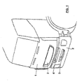
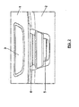
- Figures 1 and 2 show the front part of a cabin of an industrial vehicle, which has air intake openings 3, 4, 5 in the areas of the radiator grill 1 and of the bumper 2.
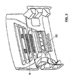
- the openings are usually provided with protection grills 6 in the internal part of the vehicle's front (shown in fig. 3 ).
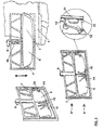
- a frame 7 with a closed structure is arranged, within which a shutter 8 can longitudinally slide (in the direction indicated by the arrow) from a lower position to an upper position.
- the sliding is driven by a linear actuator 9, for example an electric motor (or ratiomotor) whose one end is fixed to the frame, in central position, with a retractable control rod 10.
- a linear actuator 9 for example an electric motor (or ratiomotor) whose one end is fixed to the frame, in central position, with a retractable control rod 10.
- the frame 7 is applied in correspondence of an opening, for example the upper opening 3, in the internal part of the vehicle's front 1, so that the shutter 8 can completely close the opening itself ( fig. 4 up to the right), when it is placed at the one end of the frame 7, for example the lower end 8', while when it is placed at the other end 8" of the frame, it completely opens said opening, allowing the passage of the air through the vehicle.
- an opening for example the upper opening 3, in the internal part of the vehicle's front 1
- the shutter 8 slides on lateral guides or rails 11 made on the sides of the frame.
- the shutter has lateral extensions 12 which can be inserted in the guides 11, and sliding blocks 13 for example made of teflon.
- the shape of the shutter fits the shape of the opening, in order to completely close it, therefore it can be slightly convex and/or inclined.
- the vehicle's aerodynamics is thus improved.
- the sliding guides 11 are in a position that protects them from the damages caused by the weather, since the frame is bigger than the corresponding opening on the vehicle's front.
- the shutter may have stiffening ribs 14 in order to reduce the deformation due to the airflow.
- a safety mechanism may also be present on the frame, which blocks the sliding of the shutter and retracts it when external bodies are introduced in the sliding slot, in order to avoid damages to persons.
- the safety mechanism may be an infrared barrier, or a flat band/bar on the lower side of the frame having a relay: when the flat band retracts because of the presence of an object, the relay trips; or a maximum load may be set on the actuator itself, so that it stops and it retracts when the load exceeds said maximum load.
- the shutter may be made of plastic, and/or of fibrous cloth with structural characteristics having variable thickness, with acoustic insulation properties towards the outside. It may also be double-layered in order to be more stiff.
- the device according to the present invention is modular, namely more shutters may be present with their respective frame, for one or more front openings on the vehicle.
- the distance between the openings may be used as a sliding space for the open position, thus being hidden by the shutters.
- the dimensions of the frame and of the shutter are adaptable to the dimensions of the opening of the vehicle's front.
- the height of the frame is at least two times the height of the shutter.
- said device may be mounted on the vehicle as an optional also after the purchasing of the vehicle.
- Figures 3 and 5 also show a solution of a device for opening and closing air intakes comprising swinging shutters 20, 21, housed in a frame 23 connected to the vehicle's front, for example behind the air intake openings of the bumper 24.
- the hinging axis 22 of the shutters is central: thus the shutter is strengthened, the structural balancing is improved, and the longitudinal space occupied in open position is reduced, thus reducing the structural deformations due to the impact of the air.
- the shutters are placed in ducts 25 of the frame which have also the function to convey the airflow.
- the opening and closing of the shutters is driven by actuators 26 placed on the side of the frame, whose position may be completely closed and completely open as well as intermediate.
- the air intakes on the vehicle's front may have different shapes: their respective openings may be horizontally develop and be vertically adjacent, as in the attached figures, or, on the contrary, may be vertically developed and be horizontally adjacent.
- the frame may fit the shape of the openings, and possibly it may be one and only comprising more shutters, one for each opening, whose opening and closing may be independently driven. The distance between successive openings will be at least equal to the height of the shutters, so that they can take completely hidden positions.
Landscapes
- Engineering & Computer Science (AREA)
- Chemical & Material Sciences (AREA)
- Combustion & Propulsion (AREA)
- Transportation (AREA)
- Mechanical Engineering (AREA)
- Cooling, Air Intake And Gas Exhaust, And Fuel Tank Arrangements In Propulsion Units (AREA)
Abstract
Description
- The present invention refers to a device for opening and closing cooling air intakes on the front part of a vehicle.
- One of the main known problems arising in vehicles' design, especially industrial or commercial vehicles, is the reduction of fuel consumption by improving vehicle's aerodynamics.
- For example, in an industrial vehicle travelling at a speed of 90 km/h, 50% of the generated energy is spent for aerodynamics and for driving auxiliary systems, such as for example the air conditioner.
- Therefore the vehicle's aerodynamics remarkably affects the fuel consumption.
- It is known that vehicle's aerodynamics is influenced by the airflow coming from the front part of the vehicle, which is used to cool the radiator cores, the engine and the auxiliary systems, usually placed under the cabin.
- As a matter of fact, the air passing through the radiator cores is necessary to remove the heat generated (for example by the intercooler, or by the radiator, or by the condenser of the air conditioner); when the air passes through the vehicle, it passes through the fan, and other hot parts, for example the exhaust pipe, the silencers, the catalysers, and then it joins the external air flow on the back of the vehicle, generating a negative impact in terms of aerodynamics.
- When the vehicle is normally used, it is not necessary to make the engine deliver the highest possible power, for example when the vehicle is used on a highway, at constant speed, not in full load conditions. Therefore it is not necessary that the whole airflow coming from the front air intakes passes through the radiator cores, because this generates an excessive air flow rate with respect to the limit condition in which the highest possible power is delivered.
- Thus a management of the airflow through the radiator cores is actuated, from the one hand in order to make the correct quantity of air flow on the radiator cores, from the other hand in order to improve the aerodynamic behaviour, which is optimal when the front surface of the vehicle is closed as the vehicle's speed increases.
- The use of shutters that can open and close in correspondence of the air intakes on the front part of the vehicle is known in the art, in order to control the quantity of air passing through the air intakes towards the radiator cores.
- Shutters are horizontally pivoted with respect to their longitudinal axis and their upper end. As the vehicle's speed increases, shutters are gradually closed.
- The solutions known in the art, however, have potential problems essentially due to the longitudinal dimensions of the vehicle, especially in open position, in addition to the complexity of the control, the leverages and the kinematic mechanisms for moving a single shutter, as well as their tendency to be deformed by the impact of the air.
- Therefore the aim of the present invention is to provide a device for opening and closing a cooling air intake on the front part of a vehicle, suitable to overcome the drawbacks mentioned above.
- The subject of the present invention is a device for opening and closing one or more cooling air intakes on the front part of a vehicle, which, according to claim 1, is characterized in that it comprises: at least a frame with a closed structure, suitable to be applied inside said front part of the vehicle, in correspondence of said one or more air intakes; at least a shutter suitable to slide in the frame between two positions, a first of said positions being in correspondence of a respective air intake, so that in said first position the shutter completely closes the air intake, a second position leaving said air intake completely open; means for actuating said sliding.
- A particular subject of the present invention is a device for opening and closing of cooling air intake on the front part of a vehicle, as described more fully in the claims, which are an integral part of this description.
- Further purposes and advantages of the present invention will become clear from the following detailed description of a preferred embodiment (and its alternative embodiments) and the drawings that are attached hereto, which are merely illustrative and non-limitative, in which:
-
figure 1 shows a schematic view of the front part of an industrial vehicle; -
figure 2 shows a front part of the vehicle comprising air intakes; -
figure 3 shows an inner view of the front part of the vehicle; -
figure 4 shows some views of an embodiment of the device for opening and closing the air intakes according to the invention, showing how it is applied on the front part of the vehicle; -
figure 5 shows an alternative embodiment of the device, in a front and in a section view. - In the drawings the same reference numbers and letters identify the same elements or components.
- The idea at the basis of the invention is to realize a device for opening and closing the air intakes in the front part of the vehicle (radiator grill, hood or bumper) with one or more shutters which, instead of being pivoted on axles, can move up and down with a vertical movement as a function of the quantity of air that has to be introduced from the outside.
-
Figures 1 and2 show the front part of a cabin of an industrial vehicle, which hasair intake openings bumper 2. The openings are usually provided with protection grills 6 in the internal part of the vehicle's front (shown infig. 3 ). - With reference to
figure 4 , according to the present invention, a frame 7 with a closed structure is arranged, within which ashutter 8 can longitudinally slide (in the direction indicated by the arrow) from a lower position to an upper position. - The sliding is driven by a
linear actuator 9, for example an electric motor (or ratiomotor) whose one end is fixed to the frame, in central position, with aretractable control rod 10. - The frame 7 is applied in correspondence of an opening, for example the
upper opening 3, in the internal part of the vehicle's front 1, so that theshutter 8 can completely close the opening itself (fig. 4 up to the right), when it is placed at the one end of the frame 7, for example the lower end 8', while when it is placed at theother end 8" of the frame, it completely opens said opening, allowing the passage of the air through the vehicle. - The
shutter 8 slides on lateral guides orrails 11 made on the sides of the frame. For this purpose the shutter haslateral extensions 12 which can be inserted in theguides 11, and slidingblocks 13 for example made of teflon. - The shape of the shutter fits the shape of the opening, in order to completely close it, therefore it can be slightly convex and/or inclined. The vehicle's aerodynamics is thus improved.
- The
sliding guides 11 are in a position that protects them from the damages caused by the weather, since the frame is bigger than the corresponding opening on the vehicle's front. - The shutter may have stiffening
ribs 14 in order to reduce the deformation due to the airflow. - A safety mechanism (not shown) may also be present on the frame, which blocks the sliding of the shutter and retracts it when external bodies are introduced in the sliding slot, in order to avoid damages to persons. The safety mechanism may be an infrared barrier, or a flat band/bar on the lower side of the frame having a relay: when the flat band retracts because of the presence of an object, the relay trips; or a maximum load may be set on the actuator itself, so that it stops and it retracts when the load exceeds said maximum load.
- The shutter may be made of plastic, and/or of fibrous cloth with structural characteristics having variable thickness, with acoustic insulation properties towards the outside. It may also be double-layered in order to be more stiff.
- The device according to the present invention is modular, namely more shutters may be present with their respective frame, for one or more front openings on the vehicle. The distance between the openings may be used as a sliding space for the open position, thus being hidden by the shutters. The dimensions of the frame and of the shutter are adaptable to the dimensions of the opening of the vehicle's front. The height of the frame is at least two times the height of the shutter.
- Moreover said device may be mounted on the vehicle as an optional also after the purchasing of the vehicle.
- This solution occupies less longitudinal space on the vehicle, than the solutions known in the art.
-
Figures 3 and5 also show a solution of a device for opening and closing air intakes comprising swingingshutters frame 23 connected to the vehicle's front, for example behind the air intake openings of thebumper 24. - The
hinging axis 22 of the shutters is central: thus the shutter is strengthened, the structural balancing is improved, and the longitudinal space occupied in open position is reduced, thus reducing the structural deformations due to the impact of the air. - Furthermore, the shutters are placed in
ducts 25 of the frame which have also the function to convey the airflow. The opening and closing of the shutters is driven byactuators 26 placed on the side of the frame, whose position may be completely closed and completely open as well as intermediate. - It will be apparent to the person skilled in the art that other alternative and equivalent embodiments of the invention can be conceived and reduced to practice without departing from the scope of the invention.
- The air intakes on the vehicle's front may have different shapes: their respective openings may be horizontally develop and be vertically adjacent, as in the attached figures, or, on the contrary, may be vertically developed and be horizontally adjacent. In any case the frame may fit the shape of the openings, and possibly it may be one and only comprising more shutters, one for each opening, whose opening and closing may be independently driven. The distance between successive openings will be at least equal to the height of the shutters, so that they can take completely hidden positions.
- From the description set forth above it will be possible for the person skilled in the art to embody the invention with no need of describing further construction details.
Claims (8)
- Device for opening and closing one or more cooling air intakes on the front part of a vehicle, characterized in that it comprises:- at least a frame (7) with closed structure, suitable to be applied inside said front part of the vehicle, in correspondence of said one or more air intakes;- at least a shutter (8) suitable to slide inside the frame between two positions, a first of said positions being in correspondence of a respective air intake, so that in said first position the shutter completely closes a respective air intake, a second position leaving said air intake completely open;- means for actuating said sliding.
- Device as in claim 1, wherein said means for actuating the sliding comprise:- lateral guides (11) in the frame (7);- lateral extensions (12) in said at least a shutter (8), suitable to be inserted and to slide in said guides (11);- at least a linear actuator (9) applied on the frame, in order to control the sliding of said at least a shutter (8).
- Device as in claim 2, wherein said lateral extensions comprise sliding blocks (13).
- Device as in claim 2, wherein said at least a linear actuator (9) is placed on one side of the frame, centrally with respect to the shutter.
- Device as in claim 1, wherein said shutter comprises stiffening ribs (14).
- Device as in claim 1, wherein said shutter (8) may be made of plastic, and/or of fibrous cloth with structural characteristics having variable thickness, with acoustic insulation properties towards the outside of the vehicle, or being double-layered in order to be more stiff.
- Device as in any of the previous claims, comprising at least a safety mechanism on the frame, suitable to block the sliding of the shutter and to retract it in case foreign bodies are introduced in the frame.
- Vehicle comprising a device as in any of the previous claims.
Priority Applications (2)
| Application Number | Priority Date | Filing Date | Title |
|---|---|---|---|
| EP10425257.2A EP2412556B1 (en) | 2010-07-29 | 2010-07-29 | Device for opening and closing cooling air intakes on the front part of a vehicle |
| ES10425257T ES2424953T3 (en) | 2010-07-29 | 2010-07-29 | Device for opening and closing cooling air intakes on the front of a vehicle |
Applications Claiming Priority (1)
| Application Number | Priority Date | Filing Date | Title |
|---|---|---|---|
| EP10425257.2A EP2412556B1 (en) | 2010-07-29 | 2010-07-29 | Device for opening and closing cooling air intakes on the front part of a vehicle |
Publications (2)
| Publication Number | Publication Date |
|---|---|
| EP2412556A1 true EP2412556A1 (en) | 2012-02-01 |
| EP2412556B1 EP2412556B1 (en) | 2013-05-29 |
Family
ID=43302047
Family Applications (1)
| Application Number | Title | Priority Date | Filing Date |
|---|---|---|---|
| EP10425257.2A Active EP2412556B1 (en) | 2010-07-29 | 2010-07-29 | Device for opening and closing cooling air intakes on the front part of a vehicle |
Country Status (2)
| Country | Link |
|---|---|
| EP (1) | EP2412556B1 (en) |
| ES (1) | ES2424953T3 (en) |
Cited By (2)
| Publication number | Priority date | Publication date | Assignee | Title |
|---|---|---|---|---|
| CN113997782A (en) * | 2021-10-22 | 2022-02-01 | 浙江吉利控股集团有限公司 | Air inlet grille connecting structure and vehicle with same |
| CN114025980A (en) * | 2019-07-03 | 2022-02-08 | Hbpo 有限公司 | Device for shutting off a cooling module of a motor vehicle |
Families Citing this family (1)
| Publication number | Priority date | Publication date | Assignee | Title |
|---|---|---|---|---|
| US9744847B2 (en) | 2015-07-20 | 2017-08-29 | Ford Global Technologies, Llc | Flush mount active grille shutter and actuator |
Citations (3)
| Publication number | Priority date | Publication date | Assignee | Title |
|---|---|---|---|---|
| CH543669A (en) * | 1971-09-08 | 1973-10-31 | Kratzmeier Ewald | Radiator cover device for motor vehicles |
| DE102006053883A1 (en) * | 2006-11-14 | 2008-05-15 | Friedrich Graepel Ag | Radiator component for vehicle, has device for influencing amount of air flowing through radiator component, and comprising two modular sheets spaced apart from each other and arranged at radiator and/or intercooler |
| DE102006054970A1 (en) * | 2006-11-15 | 2008-05-21 | Decoma (Germany) Gmbh | Opening and closing device for air inflow opening of cooler gird, has sliding units, which are linearly movable along cooler grid, such that air inflow opening of grid is to be opened and closed by units, which move parallel to grid |
-
2010
- 2010-07-29 EP EP10425257.2A patent/EP2412556B1/en active Active
- 2010-07-29 ES ES10425257T patent/ES2424953T3/en active Active
Patent Citations (3)
| Publication number | Priority date | Publication date | Assignee | Title |
|---|---|---|---|---|
| CH543669A (en) * | 1971-09-08 | 1973-10-31 | Kratzmeier Ewald | Radiator cover device for motor vehicles |
| DE102006053883A1 (en) * | 2006-11-14 | 2008-05-15 | Friedrich Graepel Ag | Radiator component for vehicle, has device for influencing amount of air flowing through radiator component, and comprising two modular sheets spaced apart from each other and arranged at radiator and/or intercooler |
| DE102006054970A1 (en) * | 2006-11-15 | 2008-05-21 | Decoma (Germany) Gmbh | Opening and closing device for air inflow opening of cooler gird, has sliding units, which are linearly movable along cooler grid, such that air inflow opening of grid is to be opened and closed by units, which move parallel to grid |
Cited By (3)
| Publication number | Priority date | Publication date | Assignee | Title |
|---|---|---|---|---|
| CN114025980A (en) * | 2019-07-03 | 2022-02-08 | Hbpo 有限公司 | Device for shutting off a cooling module of a motor vehicle |
| CN113997782A (en) * | 2021-10-22 | 2022-02-01 | 浙江吉利控股集团有限公司 | Air inlet grille connecting structure and vehicle with same |
| CN113997782B (en) * | 2021-10-22 | 2024-10-25 | 浙江吉利控股集团有限公司 | Air intake grille connection structure and vehicle having the same |
Also Published As
| Publication number | Publication date |
|---|---|
| EP2412556B1 (en) | 2013-05-29 |
| ES2424953T3 (en) | 2013-10-10 |
Similar Documents
| Publication | Publication Date | Title |
|---|---|---|
| EP3243679B1 (en) | Charge air shutter | |
| US8684116B2 (en) | Construction machine provided with engine room | |
| RU2667696C2 (en) | Device for controlling air flow through radiator | |
| US10787141B2 (en) | AGS with displaceable actuator | |
| US20120241128A1 (en) | Heat Exchange Block For A Motor Vehicle | |
| RU141894U1 (en) | VEHICLE RADIATOR GRILLE | |
| JP5342227B2 (en) | Body front structure | |
| CN108290494A (en) | Hang grid active luffer boards | |
| US10059193B2 (en) | Grille for a vehicle, in particular a commercial vehicle as well as a vehicle | |
| KR20060110822A (en) | Car Cooling System | |
| DE102010012485A1 (en) | Cooling device for a motor vehicle | |
| CN103946048A (en) | Structure for front part of vehicle | |
| EP2412556B1 (en) | Device for opening and closing cooling air intakes on the front part of a vehicle | |
| DE102011011250A1 (en) | Cooling system for motor vehicle, has device for regulating air flow to cooler, where device has movable closure element that is movable between closed position and open position | |
| DE102016219485A1 (en) | Motor vehicle and energy storage device | |
| US20180244324A1 (en) | Vehicle air drag reducing apparatus and method of use thereof | |
| JP6105851B2 (en) | Variable duct mounting structure | |
| JP2016088118A (en) | vehicle | |
| CN204674680U (en) | For structure and the grill-protected of the vehicle with rear-mounted engine | |
| DE102010046147A1 (en) | Cooling system for motor vehicle, is provided with regulating device for air stream to cooler, where regulating device has movable flap connected between closed position and open position | |
| JP2013203316A (en) | Variable duct supporting structure | |
| JP2014024463A (en) | Vehicle front part structure | |
| CN111409447B (en) | a car air intake | |
| JP2010149623A (en) | Radiator cooling air rewind prevention structure | |
| CN214366463U (en) | Novel automobile air inlet system |
Legal Events
| Date | Code | Title | Description |
|---|---|---|---|
| AK | Designated contracting states |
Kind code of ref document: A1 Designated state(s): AL AT BE BG CH CY CZ DE DK EE ES FI FR GB GR HR HU IE IS IT LI LT LU LV MC MK MT NL NO PL PT RO SE SI SK SM TR |
|
| AX | Request for extension of the european patent |
Extension state: BA ME RS |
|
| PUAI | Public reference made under article 153(3) epc to a published international application that has entered the european phase |
Free format text: ORIGINAL CODE: 0009012 |
|
| 17P | Request for examination filed |
Effective date: 20120731 |
|
| RIC1 | Information provided on ipc code assigned before grant |
Ipc: B60K 11/08 20060101AFI20121019BHEP |
|
| GRAP | Despatch of communication of intention to grant a patent |
Free format text: ORIGINAL CODE: EPIDOSNIGR1 |
|
| GRAS | Grant fee paid |
Free format text: ORIGINAL CODE: EPIDOSNIGR3 |
|
| GRAA | (expected) grant |
Free format text: ORIGINAL CODE: 0009210 |
|
| AK | Designated contracting states |
Kind code of ref document: B1 Designated state(s): AL AT BE BG CH CY CZ DE DK EE ES FI FR GB GR HR HU IE IS IT LI LT LU LV MC MK MT NL NO PL PT RO SE SI SK SM TR |
|
| REG | Reference to a national code |
Ref country code: GB Ref legal event code: FG4D |
|
| REG | Reference to a national code |
Ref country code: CH Ref legal event code: EP |
|
| REG | Reference to a national code |
Ref country code: AT Ref legal event code: REF Ref document number: 614153 Country of ref document: AT Kind code of ref document: T Effective date: 20130615 |
|
| REG | Reference to a national code |
Ref country code: IE Ref legal event code: FG4D |
|
| REG | Reference to a national code |
Ref country code: DE Ref legal event code: R096 Ref document number: 602010007310 Country of ref document: DE Effective date: 20130725 |
|
| REG | Reference to a national code |
Ref country code: SE Ref legal event code: TRGR |
|
| REG | Reference to a national code |
Ref country code: NL Ref legal event code: T3 |
|
| REG | Reference to a national code |
Ref country code: ES Ref legal event code: FG2A Ref document number: 2424953 Country of ref document: ES Kind code of ref document: T3 Effective date: 20131010 |
|
| REG | Reference to a national code |
Ref country code: AT Ref legal event code: MK05 Ref document number: 614153 Country of ref document: AT Kind code of ref document: T Effective date: 20130529 |
|
| REG | Reference to a national code |
Ref country code: LT Ref legal event code: MG4D |
|
| PG25 | Lapsed in a contracting state [announced via postgrant information from national office to epo] |
Ref country code: IS Free format text: LAPSE BECAUSE OF FAILURE TO SUBMIT A TRANSLATION OF THE DESCRIPTION OR TO PAY THE FEE WITHIN THE PRESCRIBED TIME-LIMIT Effective date: 20130929 Ref country code: AT Free format text: LAPSE BECAUSE OF FAILURE TO SUBMIT A TRANSLATION OF THE DESCRIPTION OR TO PAY THE FEE WITHIN THE PRESCRIBED TIME-LIMIT Effective date: 20130529 Ref country code: LT Free format text: LAPSE BECAUSE OF FAILURE TO SUBMIT A TRANSLATION OF THE DESCRIPTION OR TO PAY THE FEE WITHIN THE PRESCRIBED TIME-LIMIT Effective date: 20130529 Ref country code: GR Free format text: LAPSE BECAUSE OF FAILURE TO SUBMIT A TRANSLATION OF THE DESCRIPTION OR TO PAY THE FEE WITHIN THE PRESCRIBED TIME-LIMIT Effective date: 20130830 Ref country code: NO Free format text: LAPSE BECAUSE OF FAILURE TO SUBMIT A TRANSLATION OF THE DESCRIPTION OR TO PAY THE FEE WITHIN THE PRESCRIBED TIME-LIMIT Effective date: 20130829 Ref country code: FI Free format text: LAPSE BECAUSE OF FAILURE TO SUBMIT A TRANSLATION OF THE DESCRIPTION OR TO PAY THE FEE WITHIN THE PRESCRIBED TIME-LIMIT Effective date: 20130529 Ref country code: PT Free format text: LAPSE BECAUSE OF FAILURE TO SUBMIT A TRANSLATION OF THE DESCRIPTION OR TO PAY THE FEE WITHIN THE PRESCRIBED TIME-LIMIT Effective date: 20130930 Ref country code: SI Free format text: LAPSE BECAUSE OF FAILURE TO SUBMIT A TRANSLATION OF THE DESCRIPTION OR TO PAY THE FEE WITHIN THE PRESCRIBED TIME-LIMIT Effective date: 20130529 |
|
| PG25 | Lapsed in a contracting state [announced via postgrant information from national office to epo] |
Ref country code: BG Free format text: LAPSE BECAUSE OF FAILURE TO SUBMIT A TRANSLATION OF THE DESCRIPTION OR TO PAY THE FEE WITHIN THE PRESCRIBED TIME-LIMIT Effective date: 20130829 Ref country code: HR Free format text: LAPSE BECAUSE OF FAILURE TO SUBMIT A TRANSLATION OF THE DESCRIPTION OR TO PAY THE FEE WITHIN THE PRESCRIBED TIME-LIMIT Effective date: 20130529 Ref country code: PL Free format text: LAPSE BECAUSE OF FAILURE TO SUBMIT A TRANSLATION OF THE DESCRIPTION OR TO PAY THE FEE WITHIN THE PRESCRIBED TIME-LIMIT Effective date: 20130529 |
|
| PG25 | Lapsed in a contracting state [announced via postgrant information from national office to epo] |
Ref country code: LV Free format text: LAPSE BECAUSE OF FAILURE TO SUBMIT A TRANSLATION OF THE DESCRIPTION OR TO PAY THE FEE WITHIN THE PRESCRIBED TIME-LIMIT Effective date: 20130529 |
|
| PG25 | Lapsed in a contracting state [announced via postgrant information from national office to epo] |
Ref country code: EE Free format text: LAPSE BECAUSE OF FAILURE TO SUBMIT A TRANSLATION OF THE DESCRIPTION OR TO PAY THE FEE WITHIN THE PRESCRIBED TIME-LIMIT Effective date: 20130529 Ref country code: SK Free format text: LAPSE BECAUSE OF FAILURE TO SUBMIT A TRANSLATION OF THE DESCRIPTION OR TO PAY THE FEE WITHIN THE PRESCRIBED TIME-LIMIT Effective date: 20130529 Ref country code: DK Free format text: LAPSE BECAUSE OF FAILURE TO SUBMIT A TRANSLATION OF THE DESCRIPTION OR TO PAY THE FEE WITHIN THE PRESCRIBED TIME-LIMIT Effective date: 20130529 Ref country code: BE Free format text: LAPSE BECAUSE OF FAILURE TO SUBMIT A TRANSLATION OF THE DESCRIPTION OR TO PAY THE FEE WITHIN THE PRESCRIBED TIME-LIMIT Effective date: 20130529 Ref country code: CZ Free format text: LAPSE BECAUSE OF FAILURE TO SUBMIT A TRANSLATION OF THE DESCRIPTION OR TO PAY THE FEE WITHIN THE PRESCRIBED TIME-LIMIT Effective date: 20130529 |
|
| PG25 | Lapsed in a contracting state [announced via postgrant information from national office to epo] |
Ref country code: RO Free format text: LAPSE BECAUSE OF FAILURE TO SUBMIT A TRANSLATION OF THE DESCRIPTION OR TO PAY THE FEE WITHIN THE PRESCRIBED TIME-LIMIT Effective date: 20130529 Ref country code: MC Free format text: LAPSE BECAUSE OF FAILURE TO SUBMIT A TRANSLATION OF THE DESCRIPTION OR TO PAY THE FEE WITHIN THE PRESCRIBED TIME-LIMIT Effective date: 20130529 |
|
| PLBE | No opposition filed within time limit |
Free format text: ORIGINAL CODE: 0009261 |
|
| STAA | Information on the status of an ep patent application or granted ep patent |
Free format text: STATUS: NO OPPOSITION FILED WITHIN TIME LIMIT |
|
| REG | Reference to a national code |
Ref country code: IE Ref legal event code: MM4A |
|
| 26N | No opposition filed |
Effective date: 20140303 |
|
| REG | Reference to a national code |
Ref country code: DE Ref legal event code: R097 Ref document number: 602010007310 Country of ref document: DE Effective date: 20140303 |
|
| PG25 | Lapsed in a contracting state [announced via postgrant information from national office to epo] |
Ref country code: IE Free format text: LAPSE BECAUSE OF NON-PAYMENT OF DUE FEES Effective date: 20130729 |
|
| REG | Reference to a national code |
Ref country code: CH Ref legal event code: PL |
|
| PG25 | Lapsed in a contracting state [announced via postgrant information from national office to epo] |
Ref country code: CH Free format text: LAPSE BECAUSE OF NON-PAYMENT OF DUE FEES Effective date: 20140731 Ref country code: LI Free format text: LAPSE BECAUSE OF NON-PAYMENT OF DUE FEES Effective date: 20140731 |
|
| PG25 | Lapsed in a contracting state [announced via postgrant information from national office to epo] |
Ref country code: SM Free format text: LAPSE BECAUSE OF FAILURE TO SUBMIT A TRANSLATION OF THE DESCRIPTION OR TO PAY THE FEE WITHIN THE PRESCRIBED TIME-LIMIT Effective date: 20130529 |
|
| REG | Reference to a national code |
Ref country code: FR Ref legal event code: PLFP Year of fee payment: 6 |
|
| PG25 | Lapsed in a contracting state [announced via postgrant information from national office to epo] |
Ref country code: MT Free format text: LAPSE BECAUSE OF FAILURE TO SUBMIT A TRANSLATION OF THE DESCRIPTION OR TO PAY THE FEE WITHIN THE PRESCRIBED TIME-LIMIT Effective date: 20130529 Ref country code: CY Free format text: LAPSE BECAUSE OF FAILURE TO SUBMIT A TRANSLATION OF THE DESCRIPTION OR TO PAY THE FEE WITHIN THE PRESCRIBED TIME-LIMIT Effective date: 20130529 Ref country code: TR Free format text: LAPSE BECAUSE OF FAILURE TO SUBMIT A TRANSLATION OF THE DESCRIPTION OR TO PAY THE FEE WITHIN THE PRESCRIBED TIME-LIMIT Effective date: 20130529 |
|
| PG25 | Lapsed in a contracting state [announced via postgrant information from national office to epo] |
Ref country code: HU Free format text: LAPSE BECAUSE OF FAILURE TO SUBMIT A TRANSLATION OF THE DESCRIPTION OR TO PAY THE FEE WITHIN THE PRESCRIBED TIME-LIMIT; INVALID AB INITIO Effective date: 20100729 Ref country code: LU Free format text: LAPSE BECAUSE OF NON-PAYMENT OF DUE FEES Effective date: 20130729 Ref country code: MK Free format text: LAPSE BECAUSE OF FAILURE TO SUBMIT A TRANSLATION OF THE DESCRIPTION OR TO PAY THE FEE WITHIN THE PRESCRIBED TIME-LIMIT Effective date: 20130529 |
|
| REG | Reference to a national code |
Ref country code: FR Ref legal event code: PLFP Year of fee payment: 7 |
|
| REG | Reference to a national code |
Ref country code: FR Ref legal event code: PLFP Year of fee payment: 8 |
|
| REG | Reference to a national code |
Ref country code: FR Ref legal event code: PLFP Year of fee payment: 9 |
|
| PG25 | Lapsed in a contracting state [announced via postgrant information from national office to epo] |
Ref country code: AL Free format text: LAPSE BECAUSE OF FAILURE TO SUBMIT A TRANSLATION OF THE DESCRIPTION OR TO PAY THE FEE WITHIN THE PRESCRIBED TIME-LIMIT Effective date: 20130529 |
|
| P01 | Opt-out of the competence of the unified patent court (upc) registered |
Effective date: 20230523 |
|
| PGFP | Annual fee paid to national office [announced via postgrant information from national office to epo] |
Ref country code: NL Payment date: 20250724 Year of fee payment: 16 |
|
| PGFP | Annual fee paid to national office [announced via postgrant information from national office to epo] |
Ref country code: ES Payment date: 20250812 Year of fee payment: 16 |
|
| PGFP | Annual fee paid to national office [announced via postgrant information from national office to epo] |
Ref country code: DE Payment date: 20250728 Year of fee payment: 16 |
|
| PGFP | Annual fee paid to national office [announced via postgrant information from national office to epo] |
Ref country code: IT Payment date: 20250701 Year of fee payment: 16 |
|
| PGFP | Annual fee paid to national office [announced via postgrant information from national office to epo] |
Ref country code: GB Payment date: 20250722 Year of fee payment: 16 |
|
| PGFP | Annual fee paid to national office [announced via postgrant information from national office to epo] |
Ref country code: FR Payment date: 20250725 Year of fee payment: 16 |
|
| PGFP | Annual fee paid to national office [announced via postgrant information from national office to epo] |
Ref country code: SE Payment date: 20250725 Year of fee payment: 16 |