EP2412552B1 - Warehouse industrial truck, in particular tractor or picker - Google Patents
Warehouse industrial truck, in particular tractor or picker Download PDFInfo
- Publication number
- EP2412552B1 EP2412552B1 EP11005591.0A EP11005591A EP2412552B1 EP 2412552 B1 EP2412552 B1 EP 2412552B1 EP 11005591 A EP11005591 A EP 11005591A EP 2412552 B1 EP2412552 B1 EP 2412552B1
- Authority
- EP
- European Patent Office
- Prior art keywords
- tractor
- battery
- driver
- platform
- operator
- Prior art date
- Legal status (The legal status is an assumption and is not a legal conclusion. Google has not performed a legal analysis and makes no representation as to the accuracy of the status listed.)
- Not-in-force
Links
- HBBGRARXTFLTSG-UHFFFAOYSA-N Lithium ion Chemical compound [Li+] HBBGRARXTFLTSG-UHFFFAOYSA-N 0.000 claims description 2
- OJIJEKBXJYRIBZ-UHFFFAOYSA-N cadmium nickel Chemical compound [Ni].[Cd] OJIJEKBXJYRIBZ-UHFFFAOYSA-N 0.000 claims description 2
- 229910001416 lithium ion Inorganic materials 0.000 claims description 2
- 229910052987 metal hydride Inorganic materials 0.000 claims description 2
- 238000010276 construction Methods 0.000 description 4
- 230000005484 gravity Effects 0.000 description 4
- 238000004519 manufacturing process Methods 0.000 description 4
- 230000002349 favourable effect Effects 0.000 description 2
- 238000009434 installation Methods 0.000 description 2
- 238000012423 maintenance Methods 0.000 description 2
- 239000000463 material Substances 0.000 description 2
- 239000000725 suspension Substances 0.000 description 2
- 230000006978 adaptation Effects 0.000 description 1
- 230000015572 biosynthetic process Effects 0.000 description 1
- 230000009194 climbing Effects 0.000 description 1
- 230000008030 elimination Effects 0.000 description 1
- 238000003379 elimination reaction Methods 0.000 description 1
- 230000001681 protective effect Effects 0.000 description 1
Images
Classifications
-
- B—PERFORMING OPERATIONS; TRANSPORTING
- B66—HOISTING; LIFTING; HAULING
- B66F—HOISTING, LIFTING, HAULING OR PUSHING, NOT OTHERWISE PROVIDED FOR, e.g. DEVICES WHICH APPLY A LIFTING OR PUSHING FORCE DIRECTLY TO THE SURFACE OF A LOAD
- B66F9/00—Devices for lifting or lowering bulky or heavy goods for loading or unloading purposes
- B66F9/06—Devices for lifting or lowering bulky or heavy goods for loading or unloading purposes movable, with their loads, on wheels or the like, e.g. fork-lift trucks
- B66F9/075—Constructional features or details
- B66F9/07513—Details concerning the chassis
- B66F9/07531—Battery compartments
-
- B—PERFORMING OPERATIONS; TRANSPORTING
- B60—VEHICLES IN GENERAL
- B60K—ARRANGEMENT OR MOUNTING OF PROPULSION UNITS OR OF TRANSMISSIONS IN VEHICLES; ARRANGEMENT OR MOUNTING OF PLURAL DIVERSE PRIME-MOVERS IN VEHICLES; AUXILIARY DRIVES FOR VEHICLES; INSTRUMENTATION OR DASHBOARDS FOR VEHICLES; ARRANGEMENTS IN CONNECTION WITH COOLING, AIR INTAKE, GAS EXHAUST OR FUEL SUPPLY OF PROPULSION UNITS IN VEHICLES
- B60K1/00—Arrangement or mounting of electrical propulsion units
- B60K1/04—Arrangement or mounting of electrical propulsion units of the electric storage means for propulsion
-
- B—PERFORMING OPERATIONS; TRANSPORTING
- B60—VEHICLES IN GENERAL
- B60L—PROPULSION OF ELECTRICALLY-PROPELLED VEHICLES; SUPPLYING ELECTRIC POWER FOR AUXILIARY EQUIPMENT OF ELECTRICALLY-PROPELLED VEHICLES; ELECTRODYNAMIC BRAKE SYSTEMS FOR VEHICLES IN GENERAL; MAGNETIC SUSPENSION OR LEVITATION FOR VEHICLES; MONITORING OPERATING VARIABLES OF ELECTRICALLY-PROPELLED VEHICLES; ELECTRIC SAFETY DEVICES FOR ELECTRICALLY-PROPELLED VEHICLES
- B60L53/00—Methods of charging batteries, specially adapted for electric vehicles; Charging stations or on-board charging equipment therefor; Exchange of energy storage elements in electric vehicles
- B60L53/80—Exchanging energy storage elements, e.g. removable batteries
-
- B—PERFORMING OPERATIONS; TRANSPORTING
- B62—LAND VEHICLES FOR TRAVELLING OTHERWISE THAN ON RAILS
- B62D—MOTOR VEHICLES; TRAILERS
- B62D51/00—Motor vehicles characterised by the driver not being seated
- B62D51/02—Motor vehicles characterised by the driver not being seated the driver standing in the vehicle
-
- B—PERFORMING OPERATIONS; TRANSPORTING
- B60—VEHICLES IN GENERAL
- B60K—ARRANGEMENT OR MOUNTING OF PROPULSION UNITS OR OF TRANSMISSIONS IN VEHICLES; ARRANGEMENT OR MOUNTING OF PLURAL DIVERSE PRIME-MOVERS IN VEHICLES; AUXILIARY DRIVES FOR VEHICLES; INSTRUMENTATION OR DASHBOARDS FOR VEHICLES; ARRANGEMENTS IN CONNECTION WITH COOLING, AIR INTAKE, GAS EXHAUST OR FUEL SUPPLY OF PROPULSION UNITS IN VEHICLES
- B60K1/00—Arrangement or mounting of electrical propulsion units
- B60K1/04—Arrangement or mounting of electrical propulsion units of the electric storage means for propulsion
- B60K2001/0405—Arrangement or mounting of electrical propulsion units of the electric storage means for propulsion characterised by their position
- B60K2001/0438—Arrangement under the floor
-
- B—PERFORMING OPERATIONS; TRANSPORTING
- B60—VEHICLES IN GENERAL
- B60K—ARRANGEMENT OR MOUNTING OF PROPULSION UNITS OR OF TRANSMISSIONS IN VEHICLES; ARRANGEMENT OR MOUNTING OF PLURAL DIVERSE PRIME-MOVERS IN VEHICLES; AUXILIARY DRIVES FOR VEHICLES; INSTRUMENTATION OR DASHBOARDS FOR VEHICLES; ARRANGEMENTS IN CONNECTION WITH COOLING, AIR INTAKE, GAS EXHAUST OR FUEL SUPPLY OF PROPULSION UNITS IN VEHICLES
- B60K1/00—Arrangement or mounting of electrical propulsion units
- B60K1/04—Arrangement or mounting of electrical propulsion units of the electric storage means for propulsion
- B60K2001/0455—Removal or replacement of the energy storages
- B60K2001/0461—Removal or replacement of the energy storages from the side
-
- B—PERFORMING OPERATIONS; TRANSPORTING
- B60—VEHICLES IN GENERAL
- B60Y—INDEXING SCHEME RELATING TO ASPECTS CROSS-CUTTING VEHICLE TECHNOLOGY
- B60Y2200/00—Type of vehicle
- B60Y2200/10—Road Vehicles
- B60Y2200/15—Fork lift trucks, Industrial trucks
-
- Y—GENERAL TAGGING OF NEW TECHNOLOGICAL DEVELOPMENTS; GENERAL TAGGING OF CROSS-SECTIONAL TECHNOLOGIES SPANNING OVER SEVERAL SECTIONS OF THE IPC; TECHNICAL SUBJECTS COVERED BY FORMER USPC CROSS-REFERENCE ART COLLECTIONS [XRACs] AND DIGESTS
- Y02—TECHNOLOGIES OR APPLICATIONS FOR MITIGATION OR ADAPTATION AGAINST CLIMATE CHANGE
- Y02T—CLIMATE CHANGE MITIGATION TECHNOLOGIES RELATED TO TRANSPORTATION
- Y02T10/00—Road transport of goods or passengers
- Y02T10/60—Other road transportation technologies with climate change mitigation effect
- Y02T10/70—Energy storage systems for electromobility, e.g. batteries
-
- Y—GENERAL TAGGING OF NEW TECHNOLOGICAL DEVELOPMENTS; GENERAL TAGGING OF CROSS-SECTIONAL TECHNOLOGIES SPANNING OVER SEVERAL SECTIONS OF THE IPC; TECHNICAL SUBJECTS COVERED BY FORMER USPC CROSS-REFERENCE ART COLLECTIONS [XRACs] AND DIGESTS
- Y02—TECHNOLOGIES OR APPLICATIONS FOR MITIGATION OR ADAPTATION AGAINST CLIMATE CHANGE
- Y02T—CLIMATE CHANGE MITIGATION TECHNOLOGIES RELATED TO TRANSPORTATION
- Y02T10/00—Road transport of goods or passengers
- Y02T10/60—Other road transportation technologies with climate change mitigation effect
- Y02T10/7072—Electromobility specific charging systems or methods for batteries, ultracapacitors, supercapacitors or double-layer capacitors
Definitions
- the invention relates to a tractor with a battery-electric drive system and a driver's platform for a standing operator having driver workstation, wherein for supplying the drive system, at least one battery is provided and a control arrangement is arranged at a front end of the tractor, the tractor having a vehicle frame which is provided at the front end with a wheel arranged steerable about a vertical axis and at the rear end with two laterally spaced wheels.
- the generic CA 2 344 701 A discloses in Figure 8 a tractor, which serves for pulling a trailer.
- the tractor of Figure 8 is designed as a tracked tractor comprising a left and a right track as a chassis.
- a vehicle with a 3-wheel suspension comprising a steerable front wheel and two rear wheels. In this embodiment, however, it is a pure vehicle for passenger transport of the driver.
- the EP 1 457 403 A1 discloses a pallet truck, which is operated in the pedestrian mode by an operator running in front of or next to the pallet truck and consists of a drive part and a load part consisting of two load forks.
- the top of a drive part of the pallet truck is designed as a footing, so that the operator when it stands on the raised footing on top of the drive part can also reach higher shelf level to remove goods from these shelf levels.
- a protective grid is arranged at the pallet truck between the drive part and the load part on which a climbing aid can be additionally formed with handle elements that the operator increased the climb on the Stand space easier.
- the FR 2 784 646 A1 discloses a vehicle for carrying a standing driver.
- the vehicle is provided as a tracked vehicle with a right and left crawler.
- a bracket arranged in the middle region of the vehicle allows the standing driver to hold on and carries a joystick for operating the vehicle.
- From the GB 2 423 503 A is an industrial truck with a mast known in which a battery compartment is formed below a platform of a driver's workplace.
- the intra-company transport of goods and material flow in particular the supply of material to production lines in production plants, is usually carried out by means of trailers on which the goods to be transported, in particular by means of pallets, are transported within the production plant.
- tractors In generic tractors is a battery compartment, in which a the electric drive system of the tractor supplying electrical energy battery, such as a traction battery, arranged in front of or behind the standing on the driver's platform operator in a corresponding battery compartment.
- the battery is arranged vertically standing here and usually extends over the entire vehicle width of the tractor.
- the operating arrangement is usually arranged directly vertically above the battery compartment and the battery.
- a tractor in which the battery is arranged in a battery compartment in front of the operator standing on a driver's platform and the operating arrangement is arranged directly above the battery compartment arranged in the battery compartment, is from the EP 2 108 571 A2 known.
- the present invention has for its object to provide a tractor of the type mentioned is available, which is improved in terms of length dimensions and the position of the overall center of gravity and has improved ergonomics.
- the idea according to the invention therefore consists in providing an underfloor arrangement of the battery directly below the driver's platform for the standing operator in the case of a warehouse truck designed as a tractor.
- the inventive underfloor arrangement of the battery leads in this case compared to generic tractors by the elimination of the battery compartment for the vertically arranged battery before or behind the driver's workplace to a reduced overall length of the tractor, which compact dimensions can be achieved in the tractor according to the invention, the increased maneuverability of the invention Tug give.
- a lower overall center of gravity of the tractor is achieved by the underfloor arrangement of the battery below the operator platform, which leads to improved stability of the tractor according to the invention.
- the underfloor arrangement of the battery below the driver's platform also leads to a favorable central weight distribution of the tractor in the vehicle longitudinal direction.
- advantages in terms of improved ergonomics of the tractor according to the invention are achieved because of the Removal of a battery compartment for the vertically disposed, arranged in front of or behind the driver's workplace battery front end and the rear end and thus the area in front of and behind the driver's workplace of the tractor according to the invention can be designed completely free.
- By eliminating the previously existing battery compartment in front of or behind the driver's workplace improved visibility for the operator can be achieved.
- the rear end of the tractor is in this case formed by a vertical frame wall.
- a vertical frame wall With a vertical frame wall, a high stability of the tractor in the rear end can be achieved with low construction costs, which is preferably provided with the hitch.
- a standing aid formed by a standing seat or a back cushion is also arranged for the operator standing on the driver's platform.
- the area behind the driver's workplace can be made completely free by the underfloor arrangement of the battery.
- a standing aid which is formed by a height-adjustable standing seat or a height-adjustable back cushion, the ergonomics for standing on the driver's platform operator can be improved.
- the battery compartment between a bottom-side frame plate and the driver's platform is arranged.
- an underfloor arrangement of the battery is achieved below the driver's platform with low construction costs, with a bottom-side frame plate allows high stability of the tractor according to the invention.
- the operating arrangement is formed by a driver provided with a handlebar or drawbar.
- the front end of the tractor is formed by a column provided with the operating arrangement, in particular a column which is adjustable in inclination and / or in length. Due to the underfloor arrangement of the battery below the driver platform, the front end of the tractor and thus the Area in front of the driver's workplace are completely free. This makes it possible to arrange a vertical column carrying the operating arrangement at the front end of the tractor, which can be arranged centrally or laterally. If this column is provided with a tilt adjustment and / or a length adjustability, an adjustability and adjustability of the operating arrangement can be achieved, with which the ergonomics of the operating arrangement can be improved.
- a good view to the front is achieved by the formation of the front area of the tractor by a column carrying the operating arrangement.
- the side of the column additional space is gained in front of the driver's workplace, which can be used for the cultivation of other components, in particular ergonomic components that facilitate the operation of the tractor or improve, whereby the ergonomics of the tractor according to the invention can be further increased and improved.
- a towing device is arranged at a rear end of the tractor and thus behind the driver's workplace.
- the battery can be arranged changeable in the tractor according to the invention in the battery compartment.
- the battery is arranged non-changeable in the tractor according to the invention in the battery compartment.
- the operator platform may be connected to the vehicle frame, for example, a bottom frame plate, to a supporting structure, such as a box structure, within which the battery is arranged.
- a supporting structure such as a box structure
- the accessibility of the battery for maintenance purposes or for loading or for removal and installation is ensured by the access via a side opening on one or both sides of the tractor.
- the driver's platform is arranged hinged.
- a folding operator platform easy accessibility to the battery compartment and the battery disposed therein can be achieved from above, for example, for maintenance purposes, to change the battery or exchange a discharged battery against a charged battery or to charge the battery in the battery compartment.
- a hinged operator platform with a simple additional construction effort allows a sprung and / or damped training of the driver's platform, for example by means of suitable rubber buffer, whereby the ergonomics of standing on the driver's platform operator can be further improved.
- the battery is formed according to a preferred embodiment of the invention of a lithium-ion battery or nickel-cadmium battery or nickel-metal-hydride battery.
- Such battery types have a high power density, are fast-charging and have a low dead weight.
- By using such types of battery in a tractor according to the invention can thus be achieved with the underfloor arrangement of the battery below the driver's platform by small dimensions of the battery, a low entry height.
- the quick-charging capability allows easy charging of the battery in the battery compartment.
- the low weight of such battery types also allows ergonomic installation and removal of the batteries in a battery change by hand without complex changing devices.
- the tractor according to the invention preferably has a trailer load of at most 1500 kg, in particular of at most 1250 kg.
- a tractor according to the invention which has a towing load of at most 1500 kg, in particular of at most 1250 kg, requires a corresponding reduced battery capacity, so that a small entry height can be achieved by corresponding small-sized and low space requirement batteries despite the underfloor arrangement of the battery below the driver's platform is to achieve an ergonomically favorable rise and fall for the operator on the operator platform.
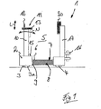
- FIG. 1 is a designed as a tractor 1 warehouse trucks displayed in a side view.
- the tractor 1 comprises a vehicle frame 2, which is provided at the front end with a wheel 3 steerably arranged about a vertical axis and at the rear end with two laterally spaced wheels 4.
- a battery-electric drive system of the tractor 1 according to the invention which comprises at least one electric traction drive motor, which may be provided for driving the steered wheel 3 and the wheels 4.
- the steering of the steered wheel can be done manually or by means of an electric steering motor, which is not shown in detail.
- a central arrangement of the steered wheel 3 can be arranged to increase the lateral stability of the tractor 1 continue in the front end side support rollers 3a.
- a driver's workplace 5 which is formed by a driver's platform 6 for a standing operator.
- a battery compartment 7 is arranged below the driver's platform 6, in which one or more batteries 8 are arranged, which supply the electrical drive system of the tractor 1 with electrical energy.
- the vehicle frame 2 has here - as in conjunction with the FIG. 2 is apparent - a bottom-side frame plate 9, wherein between the bottom-side frame plate 9 and the driver's platform 6, the battery compartment 7 is arranged, in which the batteries 8 are arranged.
- the underfloor arrangement of the batteries 8 makes it possible to make the fron workede end and the rear end of the truck 1 completely free.
- the front end of the tractor 1 is formed by a vehicle transverse direction centrally arranged vertical column 10, on which an operating arrangement 11 is arranged.
- the operating arrangement 11 is formed by a driver provided with a handlebar or drawbar 12 and may further comprise a dashboard 13, on which further control and operating elements of the tractor 1 are arranged, for example, a display or an emergency stop.
- the column 10 may in this case be provided with an inclination adjustability N and / or a length adjustability L in order to achieve an adaptation of the operating arrangement 11.
- a step 15 can be formed laterally from the column 10, which allows the operator to pick from the first shelf level.
- a towing device 16 is arranged at the rear end of the tractor 1.
- the rear end of the tractor 1 is formed by a vertical frame wall 17.
- a standing aid 20 which is formed by a standing seat or a back cushion, is arranged for standing on the driver's platform 6 operator.
- the standing aid 20 can likewise be arranged to be height-adjustable on the frame wall 17.
- the battery compartment 7 closed off from the frame plate 9 can be closed by means of two side plates to the two sides of the vehicle, so that the vehicle frame 2 seen in cross-section in the region of the battery compartment 7, has a U-shaped or trough-shaped cross-section.
- the driver's platform 6 is preferably arranged hinged on the vehicle frame 2, for example, a pivot axis arranged in the transverse direction, which can be arranged at the front or rear of the driver's platform 6.
- a pivot axis arranged in the transverse direction, which can be arranged at the front or rear of the driver's platform 6.
- the underfloor arrangement of the batteries 8 according to the invention below the driver's platform 6 results in a compact tractor with small dimensions in the vehicle longitudinal direction.
- the underfloor arrangement of the batteries 8 results from the underfloor arrangement of the batteries 8, a lower overall center of gravity, which leads to improved stability of the tractor 1.
- the underfloor arrangement of the batteries 8 enables an improved weight distribution through a substantially central arrangement of the batteries 8 between the steerable wheel 3 and the wheels 4.
Landscapes
- Engineering & Computer Science (AREA)
- Transportation (AREA)
- Mechanical Engineering (AREA)
- Structural Engineering (AREA)
- Power Engineering (AREA)
- Chemical & Material Sciences (AREA)
- Combustion & Propulsion (AREA)
- Civil Engineering (AREA)
- Life Sciences & Earth Sciences (AREA)
- Geology (AREA)
- Arrangement Or Mounting Of Propulsion Units For Vehicles (AREA)
Description
Die Erfindung betrifft einen Schlepper mit einem batterie-elektrischen Antriebssystem und einem eine Fahrerstandplattform für eine stehende Bedienperson aufweisenden Fahrerarbeitsplatz, wobei zur Versorgung des Antriebssystems mindestens eine Batterie vorgesehen ist und an einem frontseitigen Ende des Schleppers eine Bedienanordnung angeordnet ist, wobei der Schlepper einen Fahrzeugrahmen aufweist, der am frontseitigen Ende mit einem um eine vertikale Achse lenkbar angeordneten Rad und am heckseitigen Ende mit zwei seitlich beabstandeten Rädern versehen ist.The invention relates to a tractor with a battery-electric drive system and a driver's platform for a standing operator having driver workstation, wherein for supplying the drive system, at least one battery is provided and a control arrangement is arranged at a front end of the tractor, the tractor having a vehicle frame which is provided at the front end with a wheel arranged steerable about a vertical axis and at the rear end with two laterally spaced wheels.
Die gattungsbildende
Die
Die
Aus der
Der innerbetrieblichen Warentransport und Materialfluss, insbesondere die Materialversorgung von Produktionslinien in Produktionsbetrieben, erfolgt in der Regel mittels Anhängern, auf denen die zu transportierenden Waren, insbesondere mittels Paletten, innerhalb des Produktionsbetriebes transportiert werden.The intra-company transport of goods and material flow, in particular the supply of material to production lines in production plants, is usually carried out by means of trailers on which the goods to be transported, in particular by means of pallets, are transported within the production plant.
Zum Ziehen eines oder mehrerer dieser Anhänger werden als Schlepper ausgebildete Lagertechnikflurförderzeuge verwendet, die mit einer entsprechenden Anhängvorrichtung versehen sind, an denen ein oder mehrere Anhänger angehängt werden können. Derartige Schlepper weisen kompakte Abmessungen auf, wodurch die Transportanhänger innerhalb eines Produktionsbetriebes auf beengten Transportwegen sicher transportiert werden können.To pull one or more of these trailers trained as tractors warehouse trucks are used, which are provided with a corresponding Anhängvorrichtung to which one or more trailers can be attached. Such tractors have compact dimensions, whereby the transport trailer can be safely transported within a production plant on cramped transport routes.
Bei gattungsgemäßen Schleppern ist ein Batteriefach, in dem eine das elektrische Antriebssystem des Schleppers mit elektrischer Energie versorgende Batterie, beispielsweise eine Traktionsbatterie, vor oder hinter der auf der Fahrerstandplattform stehenden Bedienperson in einem entsprechenden Batteriefach angeordnet. Die Batterie ist hierbei vertikal stehend angeordnet und erstreckt sich in der Regel über die gesamte Fahrzeugbreite des Schleppers. Bei einer Anordnung der Batterie vor dem Fahrerarbeitsplatz ist in der Regel die Bedienanordnung direkt vertikal oberhalb des Batteriefachs und der Batterie angeordnet.In generic tractors is a battery compartment, in which a the electric drive system of the tractor supplying electrical energy battery, such as a traction battery, arranged in front of or behind the standing on the driver's platform operator in a corresponding battery compartment. The battery is arranged vertically standing here and usually extends over the entire vehicle width of the tractor. In an arrangement of the battery in front of the driver's workstation, the operating arrangement is usually arranged directly vertically above the battery compartment and the battery.
Ein Schlepper, bei dem die Batterie in einem Batteriefach vor der auf einer Fahrerstandplattform stehenden Bedienperson angeordnet ist und die Bedienanordnung direkt oberhalb der in dem Batteriefach angeordneten Batterie angeordnet ist, ist aus der
Die Anordnung der Batterie vor bzw. hinter dem Fahrerarbeitsplatz führt jedoch bei gattungsgemäßen Schleppern zu vergrößerten Längsabmessungen des Schleppers, wobei die stehende und vertikale Anordnung der Batterie zu einem hohen Gesamtschwerpunkt des Schleppers führt. Zudem führt die Anordnung der Batterie bei gattungsgemäßen Schleppern zu eingeschränkten Sichtverhältnissen für die Bedienperson.The arrangement of the battery in front of or behind the driver's workplace, however, leads in the case of generic tractors to increased longitudinal dimensions of the tractor, the standing and vertical arrangement of the battery leads to a high overall center of gravity of the tractor. In addition, the arrangement of the battery in generic tractors leads to limited visibility for the operator.
Der vorliegenden Erfindung liegt die Aufgabe zugrunde, einen Schlepper der eingangs genannten Gattung zur Verfügung zu stellen, das hinsichtlich der Längenabmessungen und der Lage des Gesamtschwerpunktes verbessert ist und eine verbesserte Ergonomie aufweist.The present invention has for its object to provide a tractor of the type mentioned is available, which is improved in terms of length dimensions and the position of the overall center of gravity and has improved ergonomics.
Diese Aufgabe wird erfindungsgemäß durch einen Schlepper gemäß Anspruch 1 gelöst. Der erfindungsgemäße Gedanke besteht somit darin, bei einem als Schlepper ausgebildeten Lagertechnikflurförderzeug eine Unterfluranordnung der Batterie direkt unterhalb der Fahrerstandplattform für die stehende Bedienperson vorzusehen. Die erfindungsgemäße Unterfluranordnung der Batterie führt hierbei gegenüber gattungsgemäßen Schleppern durch den Entfall des Batteriefachs für die vertikal stehend angeordnete Batterie vor bzw. hinter dem Fahrerarbeitsplatz zu einer verringerten Gesamtlänge des Schleppers, wodurch bei dem erfindungsgemäßen Schlepper kompakte Abmessungen erzielbar sind, die eine erhöhte Wendigkeit des erfindungsgemäßen Schleppers ergeben. Zudem wird durch die Unterfluranordnung der Batterie unterhalb der Fahrerstandplattform ein niedriger Gesamtschwerpunkt des Schleppers erzielt, der zu einer verbesserten Stabilität des erfindungsgemäßen Schleppers führt. Die Unterfluranordnung der Batterie unterhalb der Fahrerstandplattform führt weiterhin zu einer günstigen mittigen Gewichtsverteilung des Schleppers in Fahrzeuglängsrichtung. Zudem werden Vorteile hinsichtlich einer verbesserten Ergonomie des erfindungsgemäßen Schleppers erzielt, da durch den Entfall eines Batteriefachs für die vertikal stehende, vor bzw. hinter dem Fahrerarbeitsplatz angeordnete Batterie das frontseitige Ende bzw. das heckseitige Ende und somit der Bereich vor und hinter dem Fahrerarbeitsplatz des erfindungsgemäßen Schleppers völlig frei gestaltet werden kann. Durch den Entfall des bisher vorhandenen Batteriefachs vor oder hinter dem Fahrerarbeitsplatz kann eine verbesserte Sicht für die Bedienperson erzielt werden. Zudem wird es ermöglicht, das frontseitige Ende bzw. das heckseitige Ende des erfindungsgemäßen Schleppers durch die freie Gestaltbarkeit an ergonomische Bedingungen, beispielsweise hinsichtlich der Anordnung der Bedienanordnung und weiterer Komponenten, anzupassen. Das heckseitige Ende des Schleppers ist hierbei von einer vertikalen Rahmenwand gebildet. Mit einer vertikalen Rahmenwand kann mit geringem Bauaufwand eine hohe Stabilität des Schleppers im heckseitigen Ende erzielt werden, das bevorzugt mit der Anhängevorrichtung versehen ist. An der heckseitigen vertikalen Rahmenwand des Schleppers ist weiterhin eine von einem Stehsitz oder einem Rückenpolster gebildete Stehhilfe für die auf der Fahrerstandplattform stehende Bedienperson angeordnet. Bei dem erfindungsgemäßen Schlepper kann der Bereich hinter dem Fahrerarbeitsplatz durch die Unterfluranordnung der Batterie völlig frei gestaltet werden. Mit einer Stehhilfe, die von einem höhenverstellbaren Stehsitz oder einem höhenverstellbaren Rückenpolster gebildet ist, kann die Ergonomie für die auf der Fahrerstandplattform stehende Bedienperson verbessert werden.This object is achieved by a tractor according to
Gemäß einer bevorzugten Ausführungsform der Erfindung ist das Batteriefach zwischen einer bodenseitigen Rahmenplatte und der Fahrerstandplattform angeordnet. Hierdurch wird mit geringem Bauaufwand eine Unterfluranordnung der Batterie unterhalb der Fahrerstandplattform erzielt, wobei eine bodenseitige Rahmenplatte eine hohe Stabilität des erfindungsgemäßen Schleppers ermöglicht.According to a preferred embodiment of the invention, the battery compartment between a bottom-side frame plate and the driver's platform is arranged. As a result, an underfloor arrangement of the battery is achieved below the driver's platform with low construction costs, with a bottom-side frame plate allows high stability of the tractor according to the invention.
Gemäß einer bevorzugten Ausführungsform der Erfindung ist die Bedienanordnung von einem mit einem Fahrgeber versehenen Lenker bzw. Deichsel gebildet.According to a preferred embodiment of the invention, the operating arrangement is formed by a driver provided with a handlebar or drawbar.
Besondere Vorteile sind erzielbar, wenn gemäß einer bevorzugten Weiterbildung der Erfindung das frontseitige Ende des Schleppers von einer mit der Bedienanordnung versehenen Säule, insbesondere einer in der Neigung und/oder in der Länge verstellbaren Säule, gebildet ist. Durch die Unterfluranordnung der Batterie unterhalb der Fahrerstandplattform kann das frontseitige Ende des Schleppers und somit der Bereich vor dem Fahrerarbeitsplatz völlig frei gestaltet werden. Dadurch wird ermöglicht, eine die Bedienanordnung tragende vertikale Säule am frontseitigen Ende des Schleppers anzuordnen, die mittig oder seitlich angeordnet werden kann. Sofern diese Säule mit einer Neigungsverstellbarkeit und/oder einer Längenverstellbarkeit versehen ist, kann eine Verstellbarkeit und Einstellbarkeit der Bedienanordnung erzielt werden, mit der die Ergonomie der Bedienanordnung verbessert werden kann. Zudem wird durch die Ausbildung des frontseitigen Bereichs des Schleppers von einer die Bedienanordnung tragenden Säule eine gute Sicht nach vorne erzielt. Zudem wird seitlich der Säule zusätzlicher Bauraum vor dem Fahrerarbeitsplatz gewonnen, der zum Anbau weiterer Komponenten, insbesondere ergonomischer Komponenten, genutzt werden kann, die die Bedienung des Schleppers erleichtern bzw. verbessern, wodurch die Ergonomie des erfindungsgemäßen Schleppers weiter erhöht und verbessert werden kann.Particular advantages can be achieved if, according to a preferred development of the invention, the front end of the tractor is formed by a column provided with the operating arrangement, in particular a column which is adjustable in inclination and / or in length. Due to the underfloor arrangement of the battery below the driver platform, the front end of the tractor and thus the Area in front of the driver's workplace are completely free. This makes it possible to arrange a vertical column carrying the operating arrangement at the front end of the tractor, which can be arranged centrally or laterally. If this column is provided with a tilt adjustment and / or a length adjustability, an adjustability and adjustability of the operating arrangement can be achieved, with which the ergonomics of the operating arrangement can be improved. In addition, a good view to the front is achieved by the formation of the front area of the tractor by a column carrying the operating arrangement. In addition, the side of the column additional space is gained in front of the driver's workplace, which can be used for the cultivation of other components, in particular ergonomic components that facilitate the operation of the tractor or improve, whereby the ergonomics of the tractor according to the invention can be further increased and improved.
Bei dem erfindungsgemäßen Schlepper ist an einem heckseitigen Ende des Schleppers und somit hinter dem Fahrerarbeitsplatz eine Anhängevorrichtung angeordnet.In the tractor according to the invention a towing device is arranged at a rear end of the tractor and thus behind the driver's workplace.
Die Batterie kann bei dem erfindungsgemäßen Schlepper in dem Batteriefach wechselbar angeordnet sein.The battery can be arranged changeable in the tractor according to the invention in the battery compartment.
Alternativ ist möglich, dass die Batterie bei dem erfindungsgemäßen Schlepper in dem Batteriefach nicht-wechselbar angeordnet ist.Alternatively, it is possible that the battery is arranged non-changeable in the tractor according to the invention in the battery compartment.
Die Fahrerstandplattform kann mit dem Fahrzeugrahmen, beispielsweise einer bodenseitigen Rahmenplatte, zu einer tragenden Struktur, beispielsweise einer Kastenstruktur verbunden sein, innerhalb der die Batterie angeordnet ist. Die Zugänglichkeit der Batterie zu Wartungszwecken oder zum Laden bzw. zum Aus- und Einbau ist durch den Zugang über eine seitliche Öffnung an einer oder beiden Seiten des Schleppers gewährleistet.The operator platform may be connected to the vehicle frame, for example, a bottom frame plate, to a supporting structure, such as a box structure, within which the battery is arranged. The accessibility of the battery for maintenance purposes or for loading or for removal and installation is ensured by the access via a side opening on one or both sides of the tractor.
Besondere Vorteile sind erzielbar, wenn die Fahrerstandplattform klappbar angeordnet ist. Mit einer klappbaren Fahrerstandplattform kann eine einfache Zugänglichkeit zu dem Batteriefach und der darin angeordneten Batterie von oben erzielt werden, beispielsweise für Wartungszwecke, zum Wechseln der Batterie bzw. Austausch einer entladenen Batterie gegen eine aufgeladene Batterie oder zum Laden der Batterie im Batteriefach. Zudem ermöglicht eine klappbare Fahrerstandplattform mit einfachem zusätzlichen Bauaufwand eine gefederte und/oder gedämpfte Ausbildung der Fahrerstandplattform, beispielweise mittels geeigneter Gummipuffer, wodurch die Ergonomie für die auf der Fahrerstandplattform stehende Bedienperson weiter verbessert werden kann.Particular advantages can be achieved if the driver's platform is arranged hinged. With a folding operator platform easy accessibility to the battery compartment and the battery disposed therein can be achieved from above, for example, for maintenance purposes, to change the battery or exchange a discharged battery against a charged battery or to charge the battery in the battery compartment. In addition, a hinged operator platform with a simple additional construction effort allows a sprung and / or damped training of the driver's platform, for example by means of suitable rubber buffer, whereby the ergonomics of standing on the driver's platform operator can be further improved.
Die Batterie ist gemäß einer bevorzugten Ausgestaltungsform der Erfindung von einer Lithium-lonen-Batterie oder Nickel-Cadmium-Batterie oder Nickel-Metall-Hydrid-Batterie gebildet. Derartige Batterie-Typen weisen eine hohe Leistungsdichte auf, sind schnellladbar und weisen ein geringes Eigengewicht auf. Durch die Verwendung derartiger Batterie-Typen bei einem erfindungsgemäßen Schlepper kann somit mit der Unterfluranordnung der Batterie unterhalb der Fahrerstandplattform durch geringe Abmessungen der Batterie eine geringe Einstiegshöhe erzielt werden. Die Schnellladbarkeit ermöglicht ein einfaches Laden der Batterie im Batteriefach. Das geringe Eigengewicht derartiger Batterie-Typen ermöglicht weiterhin einen ergonomischen Ein- und Ausbau der Batterien bei einem Batteriewechsel von Hand ohne aufwändige Wechseleinrichtungen.The battery is formed according to a preferred embodiment of the invention of a lithium-ion battery or nickel-cadmium battery or nickel-metal-hydride battery. Such battery types have a high power density, are fast-charging and have a low dead weight. By using such types of battery in a tractor according to the invention can thus be achieved with the underfloor arrangement of the battery below the driver's platform by small dimensions of the battery, a low entry height. The quick-charging capability allows easy charging of the battery in the battery compartment. The low weight of such battery types also allows ergonomic installation and removal of the batteries in a battery change by hand without complex changing devices.
Das erfindungsgemäße Schlepper weist bevorzugt eine Anhängelast von höchstens 1500 kg, insbesondere von höchstens 1250 kg, auf. Ein erfindungsgemäßer Schlepper, der eine Anhängelast von höchstens 1500 kg, insbesondere von höchstens 1250 kg, aufweist, benötigt eine entsprechende verringerte Batteriekapazität, so dass durch entsprechende klein bauende und einen geringen Bauraumbedarf aufweisende Batterien trotz der Unterfluranordnung der Batterie unterhalb der Fahrerstandplattform eine geringe Einstiegshöhe erzielbar ist, um einen ergonomisch günstigen Auf- und Abstieg für die Bedienperson auf die Fahrerstandplattform zu erzielen.The tractor according to the invention preferably has a trailer load of at most 1500 kg, in particular of at most 1250 kg. A tractor according to the invention, which has a towing load of at most 1500 kg, in particular of at most 1250 kg, requires a corresponding reduced battery capacity, so that a small entry height can be achieved by corresponding small-sized and low space requirement batteries despite the underfloor arrangement of the battery below the driver's platform is to achieve an ergonomically favorable rise and fall for the operator on the operator platform.
Weitere Vorteile und Einzelheiten der Erfindung werden anhand des in den schematischen Figuren dargestellten Ausführungsbeispiels näher erläutert. Hierbei zeigt
Figur 1- einen erfindungsgemäßen Schlepper in einer Seitenansicht und
Figur 2- den Schlepper der
Figur 1
- FIG. 1
- a tractor according to the invention in a side view and
- FIG. 2
- the tug of the
FIG. 1 in a perspective view.
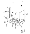
In der
Der erfindungsgemäße Schlepper 1 weist einen Fahrzeugrahmen 2 auf, der am frontseitigen Ende mit einem um eine vertikale Achse lenkbar angeordneten Rad 3 und am heckseitigen Ende mit zwei seitlich beabstandeten Rädern 4 versehen ist. Nicht näher dargestellt ist ein batterie-elektrisches Antriebssystem des erfindungsgemäßen Schleppers 1, das mindestens einen elektrischen Fahrantriebsmotor umfasst, der zum Antrieb des gelenkten Rades 3 bzw. der Räder 4 vorgesehen sein kann. Die Lenkung des gelenkten Rades kann manuell erfolgen oder mittels eines elektrischen Lenkmotors, der nicht näher dargestellt ist. Bei einer mittigen Anordnung des gelenkten Rades 3 können zur Erhöhung der seitlichen Stabilität des Schleppers 1 weiterhin im frontseitigen Ende seitliche Stützrollen 3a angeordnet werden.The
Zwischen dem frontseitigen Ende und dem heckseitigen Ende ist der erfindungemäße Schlepper 1 mit einem Fahrerarbeitsplatz 5 versehen, der von einer Fahrerstandplattform 6 für eine stehende Bedienperson gebildet ist.Between the front end and the rear end of the
Erfindungsgemäß ist unterhalb der Fahrerstandplattform 6 ein Batteriefach 7 angeordnet, in dem eine oder mehrere Batterien 8 angeordnet sind, die das elektrische Antriebssystem des Schleppers 1 mit elektrischer Energie versorgen.According to the invention, a
Der Fahrzeugrahmen 2 weist hierbei - wie in Zusammenschau mit der
Die Unterfluranordnung der Batterien 8 ermöglicht es, das fronseitige Ende und das heckseitige Ende des Flurförderzeugs 1 völlig frei zu gestalten.The underfloor arrangement of the
Im dargestellten Ausführungsbeispiel ist das frontseitige Ende des Schleppers 1 von einer in Fahrzeugquerrichtung mittig angeordneten vertikalen Säule 10 gebildet, an der eine Bedienanordnung 11 angeordnet ist.In the illustrated embodiment, the front end of the
Die Bedienanordnung 11 ist von einem mit einem Fahrgeber versehenen Lenker bzw. Deichsel 12 gebildet ist und kann weiterhin ein Armaturenbrett 13 umfassen, an dem weitere Steuer- und Bedienelemente des Schleppers 1 angeordnet sind, beispielsweise ein Display oder ein Notausschalter.The operating
Die Säule 10 kann hierbei mit einer Neigungsverstellbarkeit N und/oder einer Längenverstellbarkeit L versehen sein, um eine Anpassung der Bedienanordnung 11 zu erzielen.The column 10 may in this case be provided with an inclination adjustability N and / or a length adjustability L in order to achieve an adaptation of the operating
Wie in Verbindung mit der
Beispielsweise kann seitlich von der Säule 10 eine Trittstufe 15 ausgebildet werden, die der Bedienperson ein Kommissionieren aus der ersten Regalebene ermöglicht.For example, a
Bei dem erfindungsgemäßen als Schlepper ausgebildeten Lagertechnikflurförderzeug 1 ist an dem heckseitigen Ende des Schleppers 1 eine Anhängevorrichtung 16 angeordnet ist. Das heckseitige Ende des Schleppers 1 ist von einer vertikalen Rahmenwand 17 gebildet.In the invention designed as a tractor warehouse trucks 1 a
An dem heckseitigen Ende des Schleppers 1 ist weiterhin eine Stehhilfe 20, die von einem Stehsitz oder einem Rückenpolster gebildet ist, für die auf der Fahrerstandplattform 6 stehende Bedienperson angeordnet ist. Die Stehhilfe 20 kann hierbei ebenfalls höhenverstellbar an der Rahmenwand 17 angeordnet werden.At the rear end of the
Das von der Rahmenplatte 9 nach unten abgeschlossene Batteriefach 7 kann mittels zweier Seitenplatten zu den beiden Fahrzeugseiten abgeschlossen werden, so dass der Fahrzeugrahmen 2 im Bereich des Batteriefachs 7 im Querschnitt gesehen, einen U-förmigen bzw. wannenförmigen Querschnitt aufweist.The
Die Fahrerstandplattform 6 ist bevorzugt klappbar am Fahrzeugrahmen 2 angeordnet, beispielsweise um eine in Querrichtung angeordnete Schwenkachse, die am vorderen oder hinteren Bereich der Fahrerstandplattform 6 angeordnet werden kann. Durch Aufklappen der Fahrerstandplattform 6 kann somit eine einfache Zugänglichkeit zu den unterhalb der Fahrerstandplattform 6 angeordneten Batterien 8 erzielt werden, um diese zu laden bzw. für einen Batteriewechsel auszutauschen. Zudem kann die Fahrerstandplattform 6 gefedert und/oder gedämpft aufgehängt sein, um die Ergonomie weiter zu verbessern.The driver's
Zusätzlich zu den bereits beschriebenen Vorteilen hinsichtlich der verbesserten Sichtverhältnisse und der Ergonomie durch die freie Gestaltbarkeit des frontseitigen Endes und des heckseitigen Endes des erfindungsgemäßen Schleppers 1 ergibt die erfindungsgemäße Unterfluranordnung der Batterien 8 unterhalb der Fahrerstandplattform 6 einen kompakten Schlepper mit geringen Abmessungen in Fahrzeugslängsrichtung. Zudem ergibt sich durch die Unterfluranordnung der Batterien 8 ein tiefer Gesamtschwerpunkt, der zu einer verbesserten Stabilität des Schleppers 1 führt. Zudem ermöglicht die Unterfluranordnung der Batterien 8 eine verbesserte Gewichtsverteilung durch eine im Wesentlichen mittige Anordnung der Batterien 8 zwischen dem lenkbaren Rad 3 und den Rädern 4.In addition to the already described advantages in terms of improved visibility and ergonomics by the free configurability of the front end and the rear end of the
Mit der erfindungsgemäßen Unterfluranordnung der Batterien 8 unterhalb der Fahrerstandplattform 6 kann insbesondere bei kleinen Schleppern mit einer Anhängelast von höchstens 1250kg ein Aufbau erzielt werden, der kompakte Abmessungen mit hoher Stabilität, guten Sichtverhältnissen für die Bedienperson und verbesserter Ergonomie vereint.With the underfloor arrangement according to the invention of the
Claims (10)
- Tractor (1) having a battery-powered electric drive system and a driver workstation (5) having a driver platform (6) for a standing operator, wherein at least one battery (8) is provided in order to supply power to the drive system and an operator control arrangement (11) is arranged at a front end of the tractor (1), wherein the tractor (1) has a vehicle frame (2) which is provided at the front end with a wheel (3) which is arranged such that it can be steered about a vertical axis, and is provided at the rear end with two laterally spaced-apart wheels (4),
characterized
in that the battery compartment (7) for accommodating at least one battery (8) of the battery-powered electric drive system is formed in the region of the driver workstation (5) below the driver platform (6), in which the driver platform is connected to the vehicle frame to form a supporting structure, and also access to the battery compartment can be gained via a lateral opening on one or both sides of the tractor, wherein the rear end of the tractor (1) is formed by a vertical frame wall (17), and a standing aid (20), which is formed by a stand-up seat or a backrest cushion, for the operator standing on the driver platform (6) is arranged on the rear vertical frame wall (17) of the tractor (1). - Tractor according to Claim 1, characterized in that the battery compartment (7) is arranged between a frame plate (9) on the floor and the driver platform (6).
- Tractor according to Claim 1 or 2, characterized in that the operator control arrangement (11) is formed by a handlebar or tiller (12) which is provided with a joystick.
- Tractor according to one of Claims 1 to 3, characterized in that the front end of the tractor (1) is formed by a column (10) which is provided with the operator control arrangement (11), in particular a column of which the inclination and/or the length can be adjusted.
- Tractor according to one of Claims 1 to 4, characterized in that a trailer apparatus (16) is arranged at a rear end of the tractor (1).
- Tractor according to one of Claims 1 to 5, characterized in that the battery (8) is arranged in the battery compartment (7) in an exchangeable manner.
- Tractor according to one of Claims 1 to 5, characterized in that the battery (8) is arranged in the battery compartment (7) in a non-exchangeable manner.
- Tractor according to one of Claims 1 to 7, characterized in that the driver platform (6) is arranged such that it can be folded.
- Tractor according to one of Claims 1 to 8, characterized in that the battery (8) is formed by a lithium-ion battery or a nickel-cadmium battery or a nickel-metal hydride battery.
- Tractor according to one of Claims 1 to 9, characterized in that the tractor (1) has a towing capacity of at most 1500 kg, in particular of at most 1250 kg.
Applications Claiming Priority (2)
| Application Number | Priority Date | Filing Date | Title |
|---|---|---|---|
| DE102010032906 | 2010-07-30 | ||
| DE102010035817A DE102010035817A1 (en) | 2010-07-30 | 2010-08-30 | Warehouse trucks, in particular tractors or order pickers |
Publications (3)
| Publication Number | Publication Date |
|---|---|
| EP2412552A2 EP2412552A2 (en) | 2012-02-01 |
| EP2412552A3 EP2412552A3 (en) | 2012-05-02 |
| EP2412552B1 true EP2412552B1 (en) | 2014-09-10 |
Family
ID=44872687
Family Applications (1)
| Application Number | Title | Priority Date | Filing Date |
|---|---|---|---|
| EP11005591.0A Not-in-force EP2412552B1 (en) | 2010-07-30 | 2011-07-08 | Warehouse industrial truck, in particular tractor or picker |
Country Status (2)
| Country | Link |
|---|---|
| EP (1) | EP2412552B1 (en) |
| DE (1) | DE102010035817A1 (en) |
Cited By (1)
| Publication number | Priority date | Publication date | Assignee | Title |
|---|---|---|---|---|
| US11987483B2 (en) | 2020-06-05 | 2024-05-21 | Crown Equipment Corporation | Operator control system for a materials handling vehicle |
Families Citing this family (3)
| Publication number | Priority date | Publication date | Assignee | Title |
|---|---|---|---|---|
| US11046564B2 (en) | 2015-11-09 | 2021-06-29 | Crown Equipment Corporation | Order picker materials handling vehicle with improved downward visibility when driving elevated |
| DE102019101866A1 (en) * | 2019-01-25 | 2020-07-30 | Jungheinrich Aktiengesellschaft | Industrial truck with a battery-powered drive part |
| CN110028020B (en) * | 2019-05-14 | 2024-05-03 | 杭叉集团股份有限公司 | Picking vehicle |
Citations (2)
| Publication number | Priority date | Publication date | Assignee | Title |
|---|---|---|---|---|
| EP2103506A2 (en) * | 2008-03-17 | 2009-09-23 | Linde Material Handling GmbH | Industrial truck |
| EP2108571A2 (en) * | 2008-04-11 | 2009-10-14 | Still Sas | Tractor |
Family Cites Families (4)
| Publication number | Priority date | Publication date | Assignee | Title |
|---|---|---|---|---|
| FR2784646B1 (en) * | 1998-10-19 | 2001-01-26 | Korsak Jean Paul De | ALL TERRAIN SELF-PROPELLED PLATFORM WITH DOOR CONDUCTOR |
| CA2344701A1 (en) * | 2001-04-23 | 2002-10-23 | Michael Esselen | Creepy-crawler |
| DE10311344A1 (en) * | 2003-03-14 | 2004-09-23 | Still S.A.R.L. | Mitgängergabelhubwagen |
| GB2423503B (en) * | 2005-02-25 | 2008-08-06 | Linde Material Handling | Industrial truck having a battery block and an automatically contact-making coupling and plug connection |
-
2010
- 2010-08-30 DE DE102010035817A patent/DE102010035817A1/en not_active Withdrawn
-
2011
- 2011-07-08 EP EP11005591.0A patent/EP2412552B1/en not_active Not-in-force
Patent Citations (2)
| Publication number | Priority date | Publication date | Assignee | Title |
|---|---|---|---|---|
| EP2103506A2 (en) * | 2008-03-17 | 2009-09-23 | Linde Material Handling GmbH | Industrial truck |
| EP2108571A2 (en) * | 2008-04-11 | 2009-10-14 | Still Sas | Tractor |
Cited By (3)
| Publication number | Priority date | Publication date | Assignee | Title |
|---|---|---|---|---|
| US11987483B2 (en) | 2020-06-05 | 2024-05-21 | Crown Equipment Corporation | Operator control system for a materials handling vehicle |
| US12071333B2 (en) | 2020-06-05 | 2024-08-27 | Crown Equipment Corporation | Vertical viewing windows in a materials handling vehicle |
| US12577087B2 (en) | 2020-06-05 | 2026-03-17 | Crown Equipment Corporation | Operator control system for a materials handling vehicle |
Also Published As
| Publication number | Publication date |
|---|---|
| EP2412552A2 (en) | 2012-02-01 |
| EP2412552A3 (en) | 2012-05-02 |
| DE102010035817A1 (en) | 2012-02-02 |
Similar Documents
| Publication | Publication Date | Title |
|---|---|---|
| EP2440431B1 (en) | Heavy-duty ground transportation vehicle, in particular an unmanned heavy-duty transportation vehicle for iso containers | |
| DE69728112T2 (en) | minicar | |
| DE102017005699B3 (en) | transportation Bicycle | |
| DE102022121204A1 (en) | Vehicle frame incorporating internal battery compartments | |
| DE102017127568B3 (en) | Rollator with electric drive | |
| EP2766102A1 (en) | Electric cart | |
| DE202017107072U1 (en) | Rollator with electric drive | |
| DE202010001374U1 (en) | Electric minicar | |
| EP2627554B1 (en) | Vehicle with split driving board controllable by wheight shifting | |
| EP2412552B1 (en) | Warehouse industrial truck, in particular tractor or picker | |
| DE69720213T2 (en) | TOWING DEVICE FOR HELICOPTER WITH RUNNING LOCK | |
| DE102012103931A1 (en) | Pedestrian-controlled stacker | |
| DE112020007746T5 (en) | WORK VEHICLE | |
| EP3652052A1 (en) | Kick scooter and method for operating a scooter | |
| EP4177142A1 (en) | Load-carrying vehicle | |
| EP3907126B1 (en) | Cargo bicycle with width alteration | |
| EP2602224B1 (en) | Forklift truck, in particular order picker | |
| DE102019133724B4 (en) | Trailer cargo bike | |
| DE102008014641B4 (en) | tractor | |
| DE102018131669A1 (en) | Load carrier | |
| DE102018200111A1 (en) | Mobility system and foldable auxiliary vehicle | |
| EP0653326A1 (en) | Multi-purpose vehicle | |
| DE102006032733A1 (en) | Battery pack for an industrial truck comprises a housing containing battery cells and having openings leading into pipes inside the housing into which the fork arms of a fork lift truck can be inserted | |
| DE102005042940A1 (en) | Fork lift truck is electrically powered by lead acid battery and a fuel cell located so as to obtain good surface traction | |
| DE19700272A1 (en) | Fork-lift floor truck |
Legal Events
| Date | Code | Title | Description |
|---|---|---|---|
| AK | Designated contracting states |
Kind code of ref document: A2 Designated state(s): AL AT BE BG CH CY CZ DE DK EE ES FI FR GB GR HR HU IE IS IT LI LT LU LV MC MK MT NL NO PL PT RO RS SE SI SK SM TR |
|
| AX | Request for extension of the european patent |
Extension state: BA ME |
|
| PUAI | Public reference made under article 153(3) epc to a published international application that has entered the european phase |
Free format text: ORIGINAL CODE: 0009012 |
|
| PUAL | Search report despatched |
Free format text: ORIGINAL CODE: 0009013 |
|
| RIC1 | Information provided on ipc code assigned before grant |
Ipc: B62D 51/02 20060101ALI20120321BHEP Ipc: B60K 1/04 20060101AFI20120321BHEP Ipc: B66F 9/075 20060101ALI20120321BHEP |
|
| AK | Designated contracting states |
Kind code of ref document: A3 Designated state(s): AL AT BE BG CH CY CZ DE DK EE ES FI FR GB GR HR HU IE IS IT LI LT LU LV MC MK MT NL NO PL PT RO RS SE SI SK SM TR |
|
| AX | Request for extension of the european patent |
Extension state: BA ME |
|
| 17P | Request for examination filed |
Effective date: 20121102 |
|
| 17Q | First examination report despatched |
Effective date: 20130104 |
|
| GRAP | Despatch of communication of intention to grant a patent |
Free format text: ORIGINAL CODE: EPIDOSNIGR1 |
|
| INTG | Intention to grant announced |
Effective date: 20140221 |
|
| GRAP | Despatch of communication of intention to grant a patent |
Free format text: ORIGINAL CODE: EPIDOSNIGR1 |
|
| INTG | Intention to grant announced |
Effective date: 20140423 |
|
| GRAS | Grant fee paid |
Free format text: ORIGINAL CODE: EPIDOSNIGR3 |
|
| GRAA | (expected) grant |
Free format text: ORIGINAL CODE: 0009210 |
|
| AK | Designated contracting states |
Kind code of ref document: B1 Designated state(s): AL AT BE BG CH CY CZ DE DK EE ES FI FR GB GR HR HU IE IS IT LI LT LU LV MC MK MT NL NO PL PT RO RS SE SI SK SM TR |
|
| REG | Reference to a national code |
Ref country code: GB Ref legal event code: FG4D Free format text: NOT ENGLISH |
|
| REG | Reference to a national code |
Ref country code: CH Ref legal event code: EP |
|
| REG | Reference to a national code |
Ref country code: IE Ref legal event code: FG4D Free format text: LANGUAGE OF EP DOCUMENT: GERMAN |
|
| REG | Reference to a national code |
Ref country code: AT Ref legal event code: REF Ref document number: 686491 Country of ref document: AT Kind code of ref document: T Effective date: 20141015 |
|
| REG | Reference to a national code |
Ref country code: DE Ref legal event code: R096 Ref document number: 502011004302 Country of ref document: DE Effective date: 20141023 |
|
| PG25 | Lapsed in a contracting state [announced via postgrant information from national office to epo] |
Ref country code: GR Free format text: LAPSE BECAUSE OF FAILURE TO SUBMIT A TRANSLATION OF THE DESCRIPTION OR TO PAY THE FEE WITHIN THE PRESCRIBED TIME-LIMIT Effective date: 20141211 Ref country code: NO Free format text: LAPSE BECAUSE OF FAILURE TO SUBMIT A TRANSLATION OF THE DESCRIPTION OR TO PAY THE FEE WITHIN THE PRESCRIBED TIME-LIMIT Effective date: 20141210 Ref country code: FI Free format text: LAPSE BECAUSE OF FAILURE TO SUBMIT A TRANSLATION OF THE DESCRIPTION OR TO PAY THE FEE WITHIN THE PRESCRIBED TIME-LIMIT Effective date: 20140910 Ref country code: SE Free format text: LAPSE BECAUSE OF FAILURE TO SUBMIT A TRANSLATION OF THE DESCRIPTION OR TO PAY THE FEE WITHIN THE PRESCRIBED TIME-LIMIT Effective date: 20140910 Ref country code: LT Free format text: LAPSE BECAUSE OF FAILURE TO SUBMIT A TRANSLATION OF THE DESCRIPTION OR TO PAY THE FEE WITHIN THE PRESCRIBED TIME-LIMIT Effective date: 20140910 Ref country code: ES Free format text: LAPSE BECAUSE OF FAILURE TO SUBMIT A TRANSLATION OF THE DESCRIPTION OR TO PAY THE FEE WITHIN THE PRESCRIBED TIME-LIMIT Effective date: 20140910 |
|
| REG | Reference to a national code |
Ref country code: NL Ref legal event code: VDEP Effective date: 20140910 |
|
| REG | Reference to a national code |
Ref country code: LT Ref legal event code: MG4D |
|
| PG25 | Lapsed in a contracting state [announced via postgrant information from national office to epo] |
Ref country code: RS Free format text: LAPSE BECAUSE OF FAILURE TO SUBMIT A TRANSLATION OF THE DESCRIPTION OR TO PAY THE FEE WITHIN THE PRESCRIBED TIME-LIMIT Effective date: 20140910 Ref country code: LV Free format text: LAPSE BECAUSE OF FAILURE TO SUBMIT A TRANSLATION OF THE DESCRIPTION OR TO PAY THE FEE WITHIN THE PRESCRIBED TIME-LIMIT Effective date: 20140910 Ref country code: HR Free format text: LAPSE BECAUSE OF FAILURE TO SUBMIT A TRANSLATION OF THE DESCRIPTION OR TO PAY THE FEE WITHIN THE PRESCRIBED TIME-LIMIT Effective date: 20140910 Ref country code: CY Free format text: LAPSE BECAUSE OF FAILURE TO SUBMIT A TRANSLATION OF THE DESCRIPTION OR TO PAY THE FEE WITHIN THE PRESCRIBED TIME-LIMIT Effective date: 20140910 |
|
| PG25 | Lapsed in a contracting state [announced via postgrant information from national office to epo] |
Ref country code: NL Free format text: LAPSE BECAUSE OF FAILURE TO SUBMIT A TRANSLATION OF THE DESCRIPTION OR TO PAY THE FEE WITHIN THE PRESCRIBED TIME-LIMIT Effective date: 20140910 |
|
| PG25 | Lapsed in a contracting state [announced via postgrant information from national office to epo] |
Ref country code: SK Free format text: LAPSE BECAUSE OF FAILURE TO SUBMIT A TRANSLATION OF THE DESCRIPTION OR TO PAY THE FEE WITHIN THE PRESCRIBED TIME-LIMIT Effective date: 20140910 Ref country code: CZ Free format text: LAPSE BECAUSE OF FAILURE TO SUBMIT A TRANSLATION OF THE DESCRIPTION OR TO PAY THE FEE WITHIN THE PRESCRIBED TIME-LIMIT Effective date: 20140910 Ref country code: IS Free format text: LAPSE BECAUSE OF FAILURE TO SUBMIT A TRANSLATION OF THE DESCRIPTION OR TO PAY THE FEE WITHIN THE PRESCRIBED TIME-LIMIT Effective date: 20150110 Ref country code: RO Free format text: LAPSE BECAUSE OF FAILURE TO SUBMIT A TRANSLATION OF THE DESCRIPTION OR TO PAY THE FEE WITHIN THE PRESCRIBED TIME-LIMIT Effective date: 20140910 Ref country code: EE Free format text: LAPSE BECAUSE OF FAILURE TO SUBMIT A TRANSLATION OF THE DESCRIPTION OR TO PAY THE FEE WITHIN THE PRESCRIBED TIME-LIMIT Effective date: 20140910 Ref country code: PT Free format text: LAPSE BECAUSE OF FAILURE TO SUBMIT A TRANSLATION OF THE DESCRIPTION OR TO PAY THE FEE WITHIN THE PRESCRIBED TIME-LIMIT Effective date: 20150112 |
|
| PG25 | Lapsed in a contracting state [announced via postgrant information from national office to epo] |
Ref country code: PL Free format text: LAPSE BECAUSE OF FAILURE TO SUBMIT A TRANSLATION OF THE DESCRIPTION OR TO PAY THE FEE WITHIN THE PRESCRIBED TIME-LIMIT Effective date: 20140910 |
|
| REG | Reference to a national code |
Ref country code: DE Ref legal event code: R097 Ref document number: 502011004302 Country of ref document: DE |
|
| PLBE | No opposition filed within time limit |
Free format text: ORIGINAL CODE: 0009261 |
|
| STAA | Information on the status of an ep patent application or granted ep patent |
Free format text: STATUS: NO OPPOSITION FILED WITHIN TIME LIMIT |
|
| REG | Reference to a national code |
Ref country code: FR Ref legal event code: PLFP Year of fee payment: 5 |
|
| PG25 | Lapsed in a contracting state [announced via postgrant information from national office to epo] |
Ref country code: DK Free format text: LAPSE BECAUSE OF FAILURE TO SUBMIT A TRANSLATION OF THE DESCRIPTION OR TO PAY THE FEE WITHIN THE PRESCRIBED TIME-LIMIT Effective date: 20140910 |
|
| 26N | No opposition filed |
Effective date: 20150611 |
|
| PG25 | Lapsed in a contracting state [announced via postgrant information from national office to epo] |
Ref country code: IT Free format text: LAPSE BECAUSE OF FAILURE TO SUBMIT A TRANSLATION OF THE DESCRIPTION OR TO PAY THE FEE WITHIN THE PRESCRIBED TIME-LIMIT Effective date: 20140910 |
|
| PG25 | Lapsed in a contracting state [announced via postgrant information from national office to epo] |
Ref country code: SI Free format text: LAPSE BECAUSE OF FAILURE TO SUBMIT A TRANSLATION OF THE DESCRIPTION OR TO PAY THE FEE WITHIN THE PRESCRIBED TIME-LIMIT Effective date: 20140910 |
|
| PG25 | Lapsed in a contracting state [announced via postgrant information from national office to epo] |
Ref country code: MC Free format text: LAPSE BECAUSE OF FAILURE TO SUBMIT A TRANSLATION OF THE DESCRIPTION OR TO PAY THE FEE WITHIN THE PRESCRIBED TIME-LIMIT Effective date: 20140910 |
|
| REG | Reference to a national code |
Ref country code: CH Ref legal event code: PL |
|
| GBPC | Gb: european patent ceased through non-payment of renewal fee |
Effective date: 20150708 |
|
| PG25 | Lapsed in a contracting state [announced via postgrant information from national office to epo] |
Ref country code: LU Free format text: LAPSE BECAUSE OF FAILURE TO SUBMIT A TRANSLATION OF THE DESCRIPTION OR TO PAY THE FEE WITHIN THE PRESCRIBED TIME-LIMIT Effective date: 20150708 |
|
| REG | Reference to a national code |
Ref country code: IE Ref legal event code: MM4A |
|
| PG25 | Lapsed in a contracting state [announced via postgrant information from national office to epo] |
Ref country code: CH Free format text: LAPSE BECAUSE OF NON-PAYMENT OF DUE FEES Effective date: 20150731 Ref country code: GB Free format text: LAPSE BECAUSE OF NON-PAYMENT OF DUE FEES Effective date: 20150708 Ref country code: LI Free format text: LAPSE BECAUSE OF NON-PAYMENT OF DUE FEES Effective date: 20150731 |
|
| REG | Reference to a national code |
Ref country code: FR Ref legal event code: PLFP Year of fee payment: 6 |
|
| PG25 | Lapsed in a contracting state [announced via postgrant information from national office to epo] |
Ref country code: IE Free format text: LAPSE BECAUSE OF NON-PAYMENT OF DUE FEES Effective date: 20150708 |
|
| REG | Reference to a national code |
Ref country code: DE Ref legal event code: R082 Ref document number: 502011004302 Country of ref document: DE Representative=s name: PATENTSHIP PATENTANWALTSGESELLSCHAFT MBH, DE |
|
| REG | Reference to a national code |
Ref country code: DE Ref legal event code: R082 Ref document number: 502011004302 Country of ref document: DE Representative=s name: PATENTSHIP PATENTANWALTSGESELLSCHAFT MBH, DE |
|
| PG25 | Lapsed in a contracting state [announced via postgrant information from national office to epo] |
Ref country code: MT Free format text: LAPSE BECAUSE OF FAILURE TO SUBMIT A TRANSLATION OF THE DESCRIPTION OR TO PAY THE FEE WITHIN THE PRESCRIBED TIME-LIMIT Effective date: 20140910 |
|
| PG25 | Lapsed in a contracting state [announced via postgrant information from national office to epo] |
Ref country code: SM Free format text: LAPSE BECAUSE OF FAILURE TO SUBMIT A TRANSLATION OF THE DESCRIPTION OR TO PAY THE FEE WITHIN THE PRESCRIBED TIME-LIMIT Effective date: 20140910 Ref country code: HU Free format text: LAPSE BECAUSE OF FAILURE TO SUBMIT A TRANSLATION OF THE DESCRIPTION OR TO PAY THE FEE WITHIN THE PRESCRIBED TIME-LIMIT; INVALID AB INITIO Effective date: 20110708 Ref country code: BG Free format text: LAPSE BECAUSE OF FAILURE TO SUBMIT A TRANSLATION OF THE DESCRIPTION OR TO PAY THE FEE WITHIN THE PRESCRIBED TIME-LIMIT Effective date: 20140910 |
|
| REG | Reference to a national code |
Ref country code: FR Ref legal event code: PLFP Year of fee payment: 7 |
|
| PG25 | Lapsed in a contracting state [announced via postgrant information from national office to epo] |
Ref country code: BE Free format text: LAPSE BECAUSE OF NON-PAYMENT OF DUE FEES Effective date: 20150731 |
|
| PG25 | Lapsed in a contracting state [announced via postgrant information from national office to epo] |
Ref country code: TR Free format text: LAPSE BECAUSE OF FAILURE TO SUBMIT A TRANSLATION OF THE DESCRIPTION OR TO PAY THE FEE WITHIN THE PRESCRIBED TIME-LIMIT Effective date: 20140910 |
|
| REG | Reference to a national code |
Ref country code: AT Ref legal event code: MM01 Ref document number: 686491 Country of ref document: AT Kind code of ref document: T Effective date: 20160708 |
|
| PG25 | Lapsed in a contracting state [announced via postgrant information from national office to epo] |
Ref country code: AT Free format text: LAPSE BECAUSE OF NON-PAYMENT OF DUE FEES Effective date: 20160708 |
|
| PG25 | Lapsed in a contracting state [announced via postgrant information from national office to epo] |
Ref country code: MK Free format text: LAPSE BECAUSE OF FAILURE TO SUBMIT A TRANSLATION OF THE DESCRIPTION OR TO PAY THE FEE WITHIN THE PRESCRIBED TIME-LIMIT Effective date: 20140910 |
|
| REG | Reference to a national code |
Ref country code: FR Ref legal event code: PLFP Year of fee payment: 8 |
|
| PG25 | Lapsed in a contracting state [announced via postgrant information from national office to epo] |
Ref country code: AL Free format text: LAPSE BECAUSE OF FAILURE TO SUBMIT A TRANSLATION OF THE DESCRIPTION OR TO PAY THE FEE WITHIN THE PRESCRIBED TIME-LIMIT Effective date: 20140910 |
|
| PGFP | Annual fee paid to national office [announced via postgrant information from national office to epo] |
Ref country code: DE Payment date: 20180725 Year of fee payment: 8 Ref country code: FR Payment date: 20180723 Year of fee payment: 8 |
|
| REG | Reference to a national code |
Ref country code: DE Ref legal event code: R119 Ref document number: 502011004302 Country of ref document: DE |
|
| PG25 | Lapsed in a contracting state [announced via postgrant information from national office to epo] |
Ref country code: DE Free format text: LAPSE BECAUSE OF NON-PAYMENT OF DUE FEES Effective date: 20200201 |
|
| PG25 | Lapsed in a contracting state [announced via postgrant information from national office to epo] |
Ref country code: FR Free format text: LAPSE BECAUSE OF NON-PAYMENT OF DUE FEES Effective date: 20190731 |