EP2412539A2 - Booklet medium-handling device - Google Patents
Booklet medium-handling device Download PDFInfo
- Publication number
- EP2412539A2 EP2412539A2 EP11172114A EP11172114A EP2412539A2 EP 2412539 A2 EP2412539 A2 EP 2412539A2 EP 11172114 A EP11172114 A EP 11172114A EP 11172114 A EP11172114 A EP 11172114A EP 2412539 A2 EP2412539 A2 EP 2412539A2
- Authority
- EP
- European Patent Office
- Prior art keywords
- conveying
- state
- movable guide
- passbook
- booklet medium
- Prior art date
- Legal status (The legal status is an assumption and is not a legal conclusion. Google has not performed a legal analysis and makes no representation as to the accuracy of the status listed.)
- Granted
Links
- 230000007246 mechanism Effects 0.000 abstract description 98
- 238000004891 communication Methods 0.000 description 5
- 238000001514 detection method Methods 0.000 description 3
- 230000006870 function Effects 0.000 description 3
- 230000006835 compression Effects 0.000 description 2
- 238000007906 compression Methods 0.000 description 2
- 238000006073 displacement reaction Methods 0.000 description 2
- 230000005489 elastic deformation Effects 0.000 description 2
- 206010003402 Arthropod sting Diseases 0.000 description 1
- JOYRKODLDBILNP-UHFFFAOYSA-N Ethyl urethane Chemical compound CCOC(N)=O JOYRKODLDBILNP-UHFFFAOYSA-N 0.000 description 1
- 230000004075 alteration Effects 0.000 description 1
- 238000005452 bending Methods 0.000 description 1
- 239000013013 elastic material Substances 0.000 description 1
- 238000003780 insertion Methods 0.000 description 1
- 230000037431 insertion Effects 0.000 description 1
- 230000002452 interceptive effect Effects 0.000 description 1
- 230000001788 irregular Effects 0.000 description 1
- 239000002184 metal Substances 0.000 description 1
- 238000000034 method Methods 0.000 description 1
- 230000008520 organization Effects 0.000 description 1
- 230000008569 process Effects 0.000 description 1
- 238000006467 substitution reaction Methods 0.000 description 1
Images







Classifications
-
- B—PERFORMING OPERATIONS; TRANSPORTING
- B42—BOOKBINDING; ALBUMS; FILES; SPECIAL PRINTED MATTER
- B42D—BOOKS; BOOK COVERS; LOOSE LEAVES; PRINTED MATTER CHARACTERISED BY IDENTIFICATION OR SECURITY FEATURES; PRINTED MATTER OF SPECIAL FORMAT OR STYLE NOT OTHERWISE PROVIDED FOR; DEVICES FOR USE THEREWITH AND NOT OTHERWISE PROVIDED FOR; MOVABLE-STRIP WRITING OR READING APPARATUS
- B42D9/00—Bookmarkers; Spot indicators; Devices for holding books open; Leaf turners
- B42D9/04—Leaf turners
-
- B—PERFORMING OPERATIONS; TRANSPORTING
- B42—BOOKBINDING; ALBUMS; FILES; SPECIAL PRINTED MATTER
- B42D—BOOKS; BOOK COVERS; LOOSE LEAVES; PRINTED MATTER CHARACTERISED BY IDENTIFICATION OR SECURITY FEATURES; PRINTED MATTER OF SPECIAL FORMAT OR STYLE NOT OTHERWISE PROVIDED FOR; DEVICES FOR USE THEREWITH AND NOT OTHERWISE PROVIDED FOR; MOVABLE-STRIP WRITING OR READING APPARATUS
- B42D9/00—Bookmarkers; Spot indicators; Devices for holding books open; Leaf turners
- B42D9/04—Leaf turners
- B42D9/06—Leaf turners having an arm reset after each operation
-
- G—PHYSICS
- G07—CHECKING-DEVICES
- G07D—HANDLING OF COINS OR VALUABLE PAPERS, e.g. TESTING, SORTING BY DENOMINATIONS, COUNTING, DISPENSING, CHANGING OR DEPOSITING
- G07D9/00—Counting coins; Handling of coins not provided for in the other groups of this subclass
Definitions
- the embodiment discussed herein is related to a booklet medium-handling device.
- ATMs Automatic Teller Machines
- passbook-issuing machines installed in financial institutions, etc. are equipped with a page turning device in order to perform printing on a predetermined page of a passbook, or return a received passbook after closing the same.
- a passbook is a booklet in which a plurality of intermediate sheets are bound in a cover (including a back cover), so that the page turning device needs to perform both of operations for turning intermediate sheets which are flexible and soft and for turning covers which are flexible and relatively hard (closing the cover).
- a page turning mechanism for turning intermediate sheets and that for turning a cover are separately equipped, the page turning device becomes larger in size.
- a page turning device that realizes both of operations for turning intermediate sheets and turning a cover by one mechanism using a turning roller that swings (see e.g. Japanese Laid-Open Patent Publication No. 2009-262368 ).
- the proposed page turning device has a complex mechanism that swings the turning roller, and what is more, depending on a paper type of a passbook, the page-turning operation using the turning roller sometimes causes a paper jam.
- a booklet medium-handling device comprises a conveying section configured to convey a booklet medium, a movable guide configured to be capable of being switched between a first state in which said movable guide forms part of an upper surface of a conveying path such that said movable guide guides conveying of the booklet medium, a second state in which said movable guide is raised to open the part of the upper surface of the conveying path such that said movable guide can support one end of the booklet medium, and a third state which is an intermediate state between the first state and the second state and in which said movable guide is inclined such that said movable guide can press down the booklet medium in a direction of closing the booklet medium, a pusher configured to push up the booklet medium from an underside of the conveying path, and a controller configured to cause, when said movable guide is in the first state, said conveying section to convey the booklet medium in an opened state to a predetermined position, thereafter cause said movable guide to be switched from the first state to the second state,
- FIG. 1 is a perspective view of the page turning device according to the embodiment, in a conveying state.
- FIG. 2 is a perspective view of the page turning device according to the embodiment, in a state in which pushers are moved up and a movable guide is raised.
- FIG. 3 is a top view of the page turning device according to the embodiment, in the state in which the pushers are moved up and the movable guide is raised.
- the page turning device 1 includes a page turning mechanism, and is mounted in an automated teller machine or a passbook-issuing machine, as a page-turning unit. Further, the page turning device 1 is also capable of closing a passbook in an opened state using the page turning mechanism. Therefore, the page turning device 1 can also be regarded as a booklet-closing unit having a booklet closing mechanism.
- the page turning device 1 further includes a printing mechanism, and is mounted in an automated teller machine or a passbook-issuing machine, as a recording and printing unit.
- the page turning device 1 is a device that turns pages of a passbook (booklet medium) that is fed into a conveying path, and closes a passbook in an opened state.
- the page turning device 1 comprises a support casing 2, movable guides 3 and 4, a conveying surface 5, a shaft 20, turning rollers 21a, 21b, and 21c, conveying rollers 22a and 22b, a shaft 30, conveying rollers 31a and 31b, and pushers 200a, 200b, and 200c.
- the page turning device 1 further comprises a conveying motor 111, a mechanical cam motor 112, and a turning motor 113.
- the conveying motor 111 and the turning motor 113 are disposed at respective locations within frame lines indicated by broken lines, which are hidden behind mechanism components for transmitting the drive force (see FIG. 3 ).
- the support casing 2 supports drive mechanisms, such as the conveying motor 111, the mechanical cam motor 112, the turning motor 113, and solenoids, the shafts 20 and 30, other drive force-transmitting mechanisms, the conveying surface 5, and so on.
- Each of the movable guides 3 and 4 is one plate-like member.
- Each of the movable guides 3 and 4 which can be switched between a closed state and an open state by the mechanical cam motor 112, forms part of the upper surface of the conveying path when it is in the closed state, and supports a page to be closed backward when it is in the open state.
- the movable guides 3 and 4 are disposed along the conveying path across the shaft 20.
- the conveying surface 5 is opposed to the movable guide 3 across the conveying path when the movable guide 3 is in the closed state.
- the shaft 20 supports the turning rollers 21a, 21b, and 21c, and the conveying rollers 22a and 22b.
- the turning rollers 21a, 21b, and 21c are fixed to the shaft 20, and are rotated as the turning motor 113 drives the shaft 20 for rotation.
- the conveying rollers 22a and 22b are driven rollers which are driven for rotation by conveying rollers (drive rollers: not illustrated) opposed thereto across the conveying path.
- the conveying rollers opposed to the conveying rollers 22a and 22b across the conveying path are driven by the conveying motor 111.
- the shaft 30 supports the conveying rollers 31a and 31b.
- the conveying rollers 31a and 31b are drive rollers which are fixed to the shaft 30, and are rotated as the conveying motor 111 drives the shaft 30 for rotation.
- the conveying rollers 31a and 31b are opposed to conveying rollers 41 (driven rollers: see FIG. 5 ) across the conveying path.
- the pushers 200a, 200b, and 200c are supported on a shaft 290 (see FIG. 6 ), and are pivotally moved as the mechanical cam motor 112 drives the shaft for rotation.
- the pushers 200a, 200b, and 200c are moved (protruded) from the conveying surface 5 into the conveying path or retract therefrom, along with rotation of the shaft.
- the pushers 200a, 200b, and 200c guide a passbook 90 toward the raised movable guide 3 by pushing up the same from below.
- the pushers 200a, 200b, and 200c bend the passbook 90 by pushing up the same from below to thereby make it possible to facilitate the turning of a page of the passbook 90 by the turning rollers 21a, 21b, and 21c.
- the pushers 200a, 200b, and 200c are arranged on lines L1, L2, and L3, respectively, such that they are located within the width of the passbook 90 which is conveyed on the conveying path.
- the pusher 200b is positioned at a laterally central portion of the passbook 90 (line L2), and the pushers 200a and 200c are positioned at laterally opposite ends of the passbook 90 (lines L1 and L3).
- the pusher 200c is disposed on the line L3 which is on a magnetic stripe 91 of the passbook 90.
- the lines L1, L2, and L3 are in an irregular arrangement in which the distance between the lines L2 and L3 is narrower than that between the lines L1 and L2. Further, the turning rollers 21a, 21b, and 21c are disposed on the lines L1, L2, and L3, respectively.
- the passbook 90 used here is configured as a booklet in which a plurality of inside sheets which are relatively low in rigidity (soft) are bound in a cover which is relatively high in rigidity (hard).
- the passbook 90 is in an open state with a binding stitch line portion in the center, and the cover of the passbook 90 is formed with the belt-like magnetic stripe 91 having a predetermined thickness. It is possible to record necessary information in the magnetic stripe 91, and information can be read from or written in the magnetic stripe 91 by a reader/writer, not illustrated.
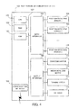
- FIG. 4 illustrates an example of the hardware configuration of a page turning mechanism controller according to the embodiment.
- a page turning mechanism controller 100 is provided in the page turning device 1. It should be noted that the page turning mechanism controller 100 may be equipped in e.g. a PPR (Passbook Printer) unit having not only the page turning mechanism, but also a magnetic stripe-reading mechanism and a printing mechanism.
- PPR Passbook Printer
- a CPU Central Processing Unit 101 controls the above-mentioned mechanisms.
- a RAM Random Access Memory
- ROM Read Only Memory
- a communication interface 104 an input interface 105, and an output interface 106 are connected to the CPU 101 via a system bus 107.
- the RAM 102 temporarily stores at least part of a program of an OS (Operating System) and application programs which the CPU 101 is caused to execute. Further, the RAM 102 stores various data which are necessary for processing by the CPU 101.
- the ROM 103 stores the OS program and the application programs.
- the communication interface 104 is connected to other controllers via a communication line. For example, the communication interface 104 is connected to a main controller that performs unified control of an automated teller machine or a passbook-issuing machine.
- the input interface 105 includes a plurality of sensors, such as position-detecting sensors 108, 109, and 110 for detecting positions of the turning rollers, a booklet medium which is conveyed, and so on, and inputs detection signals delivered from these various sensors.
- the position-detecting sensors 108, 109, and 110 are e.g. photo sensors which detect a booklet medium existing between a light-emitting element and a light-receiving element based on a light-blocking state and a light-passing state thereof.
- the output interface 106 outputs signals for controlling the conveying motor 111, the mechanical cam motor 112, the turning motor 113, and a solenoid 114.
- the conveying motor 111, the mechanical cam motor 112, and the turning motor 113 are stepping motors, which can be driven for clockwise rotation and counterclockwise rotation by the control signal.
- the solenoid 114 performs the stroke operation according to an ON-OFF control signal.
- the page turning device 1 can be configured such that it comprises modules formed by an FPGA (Field programmable Gate Array), a DSP (Digital Signal Processor), etc., and can be also configured to be without the CPU 101.
- the page turning device 1 includes a nonvolatile memory (e.g. EEPROM (Electrically Erasable and Programmable Read Only Memory), a flash memory, a flash memory-type memory card, etc.), which stores firmware of the modules. It is possible to write the firmware in the nonvolatile memory via a transportable storage medium or the communication interface 104. Thus, the page turning device 1 can update the firmware by rewriting the firmware stored in the nonvolatile memory.
- EEPROM Electrical Erasable and Programmable Read Only Memory
- FIG. 5 is a schematic view of essential parts useful in explaining the page turning mechanism according to the embodiment.
- the page turning mechanism 10 as a mechanism for conveying the passbook 90, includes the conveying surface 5, the conveying rollers 31 and conveying rollers 51 and 61 as drive rollers, and the conveying rollers 22 and conveying rollers 41 and 71 as driven rollers.
- Each conveying roller 61 is opposed to an associated one of the conveying rollers 71 across the conveying path (first pair of conveying rollers)
- each conveying roller 51 is opposed to an associated one of the conveying rollers 22 across the conveying path (third pair of conveying rollers)
- each conveying roller 31 is opposed to an associated one of the conveying rollers 41 across the conveying path (second pair of conveying rollers).
- the conveying path is formed by a conveying path upper surface and a conveying path lower surface.
- the conveying path upper surface is formed by the movable guides 3 and 4, and a guide 6, and the conveying path lower surface is formed by the conveying surface 5, and pushers 200 and 300.
- the page turning mechanism 10 includes one page turning mechanism (first page turning mechanism) comprising the movable guide 3, the conveying surface 5, the guide 6, the turning rollers 21, the conveying rollers 22, 31, 41, and 51, and the pushers 200. Further, the page turning mechanism 10 includes the other page turning mechanism (second page turning mechanism) comprising the movable guide 4, the conveying surface 5, the guide 6, the turning rollers 21, the conveying rollers 22, 51, 61, and 71, and the pushers 300. That is, the page turning mechanism 10 has two page turning mechanisms that share the turning rollers 21 and the conveying rollers 22 and 51 therebetween. Further, the page turning mechanism 10 has two booklet-closing mechanisms that share the turning rollers 21, and the conveying rollers 22, 31, 41, 51, 61, and 71. The page turning mechanism 10 has the booklet-closing mechanisms which are opposed to each other (oriented in different directions), whereby it is possible to close the passbook 90 in a manner pointing the binding stitch line portion in any directions.
- first page turning mechanism comprising the movable guide 3,
- first page turning mechanism performs a page-turning operation for paging forward, in a sharing manner
- second page turning mechanism performs a page-turning operation for paging backward, in a sharing manner.
- first page turning mechanism performs the page-turning operation for paging forward, in a sharing manner
- second page turning mechanism performs the page-turning operation for paging backward, in a sharing manner.
- one of the first and second page turning mechanisms performs a booklet-closing operation for closing a booklet such that the front cover is positioned on the top side, in a sharing manner
- the other performs a booklet-closing operation for closing the booklet such that the back cover is positioned on the top side, in a sharing manner
- the first page turning mechanism performs the booklet-closing operation for closing the booklet such that the front cover is positioned on the top side, in a sharing manner
- the second page turning mechanism performs the booklet-closing operation for closing the booklet such that the back cover is positioned on the top side, in a sharing manner.
- Each conveying roller 51 is rotatably fixed to a shaft, not illustrated, which transmits the driving force from the conveying motor 111.
- the conveying roller 51 can be moved up and down with respect to the conveying path by the driving force from the mechanical cam motor 112.
- the conveying roller 51 has its roller surface brought into contact with the passbook 90 to urge the passbook 90 between the conveying roller 51 and the conveying roller 22, and rotates to move the passbook 90 along the conveying path.
- the conveying roller 22 is rotatably supported on the shaft 20 and is driven by the rotation of the conveying roller 51.
- the turning roller 21 is rotatably fixed to the shaft 20 which transmits the driving force from the turning motor 113.
- the turning roller 21 is fixed to the shaft 20 which supports the conveying roller 22.
- the turning roller 21 is formed of an elastic material having a relatively high frictional force, such as rubber, and includes a main body having a substantially fan-shaped cross section, and a curved surface portion of the fan-shaped part forms a friction contact surface which is brought into contact with a page to be turned.
- the turning roller 21 has its curved friction contact surface brought into contact with the page to be turned to produce friction therebetween.
- the three turning rollers 21 are provided on the shaft at the same mounting angle, and simultaneously press down the passbook 90 at a plurality of points (e.g. three points: left, right and center). Further, the distance from the friction contact surface to the center of the shaft is made larger than a radius of the conveying roller 22. Further, the conveying surface 5 has a recess formed in the vicinity of the turning roller 21 so as not to interfere with the turning roller 21.
- Each conveying roller 31 is rotatably fixed to the shaft 30 which transmits the driving force from the conveying motor 111.
- the conveying roller 31 has its roller surface brought into contact with the passbook 90 to urge the passbook 90 between the conveying roller 31 and an associated one of the conveying rollers 41, and rotates to move the passbook 90 along the conveying path.
- Each conveying roller 41 which is rotatably supported on a shaft, can be moved up and down with respect to the conveying path, and is driven by the rotation of the conveying roller 31.
- Each pusher 200 is rotatably fitted on the shaft 290 which transmits the driving force from the mechanical cam motor 112 and can be moved up and down with respect to the conveying path.
- the pusher 200 has a pusher main body thereof brought into contact with a portion of the back cover of the passbook 90 corresponding to a page to be turned and then pushes up the passbook 90. Details of the pusher 200 will be described hereinafter.
- the movable guide 3 can be switched between the closed state and the open state by a driving force from the mechanical cam motor 112 and forms the upper surface of the conveying path in the closed state thereof.
- the movable guide 3 avoids interference with the passbook 90 pushed up by the pusher 200 when it is in the open state.
- the movable guide 3 supports a page turned up by the turning roller 21.
- the conveying surface 5 and the guide 6 form a fixed passbook-sliding surface.
- the fixed passbook-sliding surface extends in a forward-rearward direction of the conveying path in a manner avoiding areas where the passbook 90 can interfere with movable members, and forms part of the conveying path.
- FIG. 6 is a perspective view of the pusher mechanism according to the embodiment.
- FIG. 7 is an exploded perspective view of the pusher mechanism according to the embodiment.
- the pusher mechanism comprises the pusher 200 and a drive unit which drives the pusher 200.
- the drive unit comprises the mechanical cam motor 112 (drive device) and the shaft (drive section) 290 which transmits the driving force from the mechanical cam motor 112.
- the pusher 200 comprises the pusher main body 210, a pusher guide (base portion) 220, and a spring 230.
- the pusher main body 210 is pivotally supported on the shaft 290 which is inserted through a shaft insertion hole 218.
- the pusher main body 210 has a contact surface 211, a contact surface 212, a conveying surface 213, a tapered surface 214, a conveying surface 215, and a tapered surface 216, on a side toward the conveying surface 5.
- the conveying surface 213, the tapered surface 214, and the conveying surface 215 are substantially flush with the conveying surface 5 when the pusher 200 is in a state retracted from the conveying path 5.
- the tapered surfaces 214 and 216 each have a predetermined inclination with respect to the conveying surface 215 in order to reduce conveying resistance of the passbook 90.
- the contact surface 212 is brought into contact with the passbook 90, which is an object to be pushed up, when the pusher 200 is in a state moved into the conveying path from the conveying surface 5.
- the contact surface 212 is brought into contact with the cover of the passbook 90, which is an object to be closed, when the pusher 200 is in the state moved into the conveying path from the conveying surface 5.
- the pusher guide 220 is a member formed by bending a plate-shaped sheet metal member, and has a first recess 223, which is U-shaped in cross section, at a central portion thereof, a second recess 224, which is U-shaped in cross section, at one end adjacent to the first recess 223, and a spring placing portion 225, which is tongue-shaped, at the other end adjacent to the first recess 223.
- the first recess 223 has stopper portions 221 on opposite sides of a bottom thereof. The first recess 223 prevents the pusher guide 220 from interfering with a drive shaft (shaft) of other movable members when the pusher 200 is in a state not protruded from the conveying surface 5.
- the second recess 224 has a guide hole 222 in a bottom thereof.
- the pusher guide 220 is fixed to the shaft 290 by inserting the shaft 290 through the second recess 224, inserting a small screw 240 through the guide hole 222, and screwing the screw 240 into a screw hole 291.
- the spring 230 is placed (supported) on the spring placing portion 225.
- the pusher main body 210 is supported by the spring 230 formed by a compression spring.
- the rotation of the shaft 290 is transmitted to the pusher main body 210 via the pusher guide 220 and the spring 230 interposed between the pusher guide 220 and the pusher main body 210.
- an amount of pivotal movement of the pusher main body 210 is limited to less than an amount of pivotal movement of the shaft 290 and the pusher guide 220 due to elastic deformation (compression) of the spring 230. Therefore, the sprig 230 functions as a pivotal movement amount (displacement amount)-limiting section which limits the amount of pivotal movement of the pusher main body 210.
- the spring 230 may be a torsion spring, a helical extension spring or any other like spring, and is not limited to a spring, but may be rubber, urethane, or any other like elastic member, insofar as it limits the displacement amount by elastic deformation.
- Limit amount-restricting portions 217 are in the form of window frames that open in the pusher main body 210, and limit an amount of pivotal movement of the pusher main body 210 relative to the pusher guide 220 by being brought into abutment with the stopper portions 221 which move within the respective window frames.
- Each limit amount-restricting portion 217 is brought into abutment with an associated one of the stopper portions 221 via a lower end of the window frame thereof when the pusher main body 210 is in a state having no load placed thereon, and is brought into abutment with the associated stopper portion 221 via an upper end of the window frame thereof when the pusher main body 210 is in a state having load larger than the predetermined load placed thereon.
- the stopper portions 221 which are brought into abutment with the respective limit amount-restricting portions 217 via the upper ends of the window frames with the spring 230 being compressed by not less than a predetermined amount support the pusher main body 210, in cooperation with the spring 230. Therefore, the spring 230 is never compressed by more than a predetermined amount.
- the limit amount-restricting portions 217 have a function of restricting the limit amount of pivotal movement of the pusher main body 210 which the spring 230 limits, within a predetermined range.
- the pusher main body 210 can adjust the amount of bend of the passbook 90 pushed up thereby within the predetermined range. More specifically, when the passbook 90 pushed up by the pusher main body 210 is thin, the load placed on the contact surface 212 is small, so that the pusher main body 210 is pivoted by an amount of pivotal movement equal to the amount of pivotal movement of the pusher guide 220. When the passbook 90 pushed up by the pusher main body 210 is thick, the load placed on the contact surface 212 is large, so that the pusher main body 210 is pivoted by less than the amount of pivotal movement of the pusher guide 220.
- the pusher main body 210 when performing the operation for closing the passbook 90, the pusher main body 210 can be brought into contact with the passbook 90 also via the contact surface 211 by increasing the amount of pivotal motion of the shaft 290. At this time, the pusher main body 210 is subjected to load in a direction substantially perpendicular to a direction of deforming the spring 230. Further, when the pusher main body 210 is subjected to load due to the sliding resistance of the passbook 90, the limit amount-restricting portions 217 restrict the limit amount of pivotal movement of the pusher main body 210 within the predetermined range, and hence the contact surface 211 is properly brought into contact with the passbook 90.
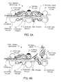
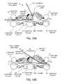
- FIGS. 8 to 11 are views useful in explaining the booklet-closing operation of the page turning mechanism according to the embodiment.
- FIG. 12 is a timing chart useful in explaining timings of the booklet-closing operation of the page turning mechanism according to the embodiment.
- the page turning mechanism controller 100 receives a passbook-closing instruction from a main controller to start the passbook-closing operation.
- the page turning mechanism controller 100 drives the conveying motor 111 for counterclockwise rotation at timing p1 to convey the passbook 90 drawn in by the page turning mechanism 10 toward the right as viewed in the figure (see FIG. 8A ).
- the conveying roller pair formed by the conveying rollers 61 and 71 and the conveying roller pair formed by the conveying rollers 22 and 51 hold and convey the passbook 90 in a sandwiching manner, respectively.
- the position-detecting sensor 108 disposed on the conveying path detects the passbook 90, and is switched from OFF to ON (timing p2).
- the page turning mechanism controller 100 receives a detection signal delivered from the position-detecting sensor 108 (passbook detection signal) to drive the mechanical cam motor 112 for counterclockwise rotation (timing p3). Then, the page turning mechanism controller 100 drives the mechanical cam motor 112 for the counterclockwise rotation by a predetermined number of steps, and then stops the same (timing p4). This changes the position of the movable guide 3 such that the movable guide 3 is raised from the closed state (first state) in which the movable guide 3 forms part of the upper surface of the conveying path into the open state (second state) in which the movable guide 3 opens part of the upper surface of the conveying surface. Further, the pusher 200 is brought into contact with the passbook 90 via the contact surface 211 to push up one end of the passbook 90 in the opened state. Further, the conveying roller 51 is retracted from the conveying path (see FIG. 8B ).
- the page turning mechanism controller 100 drives the conveying motor 111 for counterclockwise rotation at timing p5 to further convey the passbook 90 toward the right as viewed in FIG. 8B .
- the passbook 90 is conveyed while the one end thereof is being pushed up by the pusher 200, and hence the one end of the passbook 90 is conveyed toward the raised movable guide 3 above the conveying path.
- the one end of the passbook 90 is brought into contact with the movable guide 3, and then is slid onto the top of the movable guide 3 while being slid upward.
- the page turning mechanism controller 100 drives the conveying motor 111 for counterclockwise rotation by a predetermined number of steps and then stop the same (timing p6). At this time, the one end of the passbook 90 is supported on the top of the movable guide 3.
- the conveying roller 22 is brought into contact with portions across the binding stitch line portion of the passbook 90 (see FIG. 9A ).
- the page turning mechanism controller 100 drives the mechanical cam motor 112 for clockwise rotation at timing p7.
- the page turning mechanism controller 100 drives the mechanical cam motor 112 for clockwise rotation by a predetermined number of steps, and then stops the same (timing p8). This causes the pusher 200 to be retracted from the conveying path. Further, the conveying roller 51 is moved into the conveying path, and is opposed to the conveying roller 22 across the passbook 90.
- the page turning mechanism controller 100 drives the conveying motor 111 for counterclockwise rotation at timing p9 to further convey the passbook 90 toward the right as viewed in FIG. 9B .
- the page turning mechanism controller 100 drives the conveying motor 111 for counterclockwise rotation by a predetermined number of steps, and then stops the same (timing p10).
- the passbook 90 is stopped at a position where the passbook 90 has passed by a distance approximately equal to the radius of the conveying roller 22 from the position where the conveying roller 22 and the binding stich line portion are brought into contact with each other (see FIG. 9B ).
- the page turning mechanism controller 100 starts to drive the turning motor 113 for counterclockwise rotation at timing p11.
- the page turning mechanism controller 100 drives the turning motor 113 for counterclockwise rotation by a predetermined number of steps, and then stops the same (timing p12). This causes the turning roller 21 to be retracted from the initial position to a position (retracted position) where the turning roller 21 is not brought into contact with the passbook 90 during the closing operation.
- the page turning mechanism controller 100 starts to drive the mechanical cam motor 112 for clockwise rotation at timing p13. Then, the page turning mechanism controller 100 drives the mechanical cam motor 112 for clockwise rotation by a predetermined number of steps, and then stops the same (timing p14). This changes the position of the movable guide 3 such that it is fallen from the open state (second state) in which the movable guide 3 is raised to open part of the upper surface of the conveying surface into an inclined state in which the movable guide 3 is an intermediate state between the open state and the closed state (third state) (see FIG. 10A ).
- the movable guide 3 falls from the raised state in which the one end of the passbook 90 is supported on the top of the movable guide 3, to thereby place the one end side of the passbook 90 in the opened state over the conveying roller 22. At this time, the movable guide 3 is brought into contact with a portion of the passbook 90, which is closer to the one end than a portion of the opened passbook 90 with which the conveying roller 22 is brought into contact.
- the passbook 90 is closed backward at a sharp angle about the binding stitch line portion in the center before the binding stitch line portion is held between the conveying roller pair formed by the conveying rollers 31 and 41 in a sandwiching manner.
- the movable guide 3 presses down the portion, which is more shifted toward the one end, of the passbook 90 in the opened state by the pivotal movement, compared with a case where the binding stitch line portion of the passbook 90 or its vicinity is pressed down, it is possible to reduce the load placed on the passbook 90. This reduces the possibility that the load placed on the passbook 90 becomes too large, causing the passbook 90 to be moved out, whereby the page turning mechanism 10 fails to perform the passbook-closing operation.
- the movable guide 3 is driven by the mechanical cam motor 112 at this time, and hence it is possible to place larger load on the passbook 90 than when pressing the passbook 90 with the self weight of the movable guide 3. Therefore, even when the paper type of the passbook 90 is flexible and relatively hard, the movable guide 3 can properly perform the operation for closing the passbook 90. Further, even when the passbook 90 has a lot of pages to be closed, the movable guide 3 can properly perform the operation for closing the passbook 90.
- the movable guide 3 in the inclined state is spaced from the conveying roller 22 with a predetermined gap.
- the predetermined gap is set to a value larger than a thickness of pages on one open side which are to be closed of the passbook 90. It should be noted that the size of the gap can be varied according to a type of the passbook 90 and the position of opened pages thereof.
- the page turning mechanism controller 100 drives the conveying motor 111 for counterclockwise rotation at timing p15 to further convey the passbook 90 toward the right as viewed in FIG. 10B .
- the conveying roller pair formed by the conveying rollers 31 and 41 and the conveying roller pair formed by the conveying rollers 22 and 51 hold and convey the passbook 90 in a sandwiching manner (see FIG. 10B ).
- the passbook 90 is closed backward at a sharp angle about the binding stitch line portion in the center, which prevents the load placed on the conveying rollers 31 and 41 from becoming too large when conveying the passbook 90.
- the page turning mechanism controller 100 drives the conveying motor 111 for counterclockwise rotation by a predetermined number of steps, and then stops the same (timing p16). At this time, the passbook 90 is held by the conveying roller pair formed by the conveying rollers 31 and 41 in a sandwiching manner, and the end of the open side of the closed passbook 90 (opposite to the binding stitch line portion in a closed state of the passbook 90) is positioned between the conveying roller pair formed by the conveying rollers 31 and 41 and the conveying roller pair formed by the conveying rollers 22 and 51.
- the passbook 90 being conveyed has the closed cover (including intermediate sheets, if any) slid between the conveying roller 22 and the movable guide 3. Therefore, the passbook 90 is only conveyed such that the passbook 90 is drawn into the conveying roller pair formed by the conveying rollers 31 and 41, so that too large load is prevented from being applied to the closed cover. As a result, the page turning mechanism 10 reduces the possibility of causing a paper jam of the passbook 90.
- the page turning mechanism controller 100 drives the mechanical cam motor 112 for clockwise rotation at a timing p17. Then, the page turning mechanism controller 100 drives the mechanical cam motor 112 for clockwise rotation by a predetermined number of steps, and then stops the same (timing p18). This changes the position of the movable guide 3 from the state in which the movable guide 3 is inclined, which is the intermediate state between the open state and the closed state (third state), into the closed state in which the movable guide 3 forms part of the upper surface of the conveying path (first state).
- the page turning mechanism controller 100 drives the turning motor 113 for clockwise rotation at timing p19.
- the page turning mechanism controller 100 drives the turning motor 113 for clockwise rotation by a predetermined number of steps, and then stops the same (timing p20). This causes the turning roller 21 to return from a retracted position to the initial position (see FIG. 11 ).
- the page turning mechanism controller 100 drives the conveying motor 111 for clockwise rotation at timing p21. Then, the page turning mechanism controller 100 drives the conveying motor 111 for clockwise rotation by a predetermined number of steps, and then stops the same (timing p22). At this time, the conveying roller pair formed by the conveying rollers 31 and 41, the conveying roller pair formed by the conveying rollers 22 and 51, and the conveying roller pair formed by the conveying rollers 61 and 71 hold and convey the passbook 90 in a sandwiching manner. The passbook 90 is conveyed to a position where the passbook 90 is discharged from the page turning mechanism 10.
- the page turning mechanism 10 can perform the operation for stably closing the passbook 90 by the simple structure.
- the page turning mechanism 10 can perform the booklet-closing operation not only from a state in which only one cover is to be closed but also from any pages of the passbook 90. Therefore, during the booklet-closing operation, the page turning operation is not necessary and hence the page turning mechanism 10 can reduce the processing time of the booklet-closing operation.
- the page turning mechanism 10 configured as above is mounted in an automated teller machine or a passbook-issuing machine, it is possible to reduce the time necessary to provide services.
- the page turning mechanism controller 100 may repeatedly carry out an operation for opening and closing the movable guide 3. By performing this repeating operation, it is possible to make the passbook 90 flexible and soft, whereby it is possible to further reduce load on the operation of conveying the passbook 90.
- the pusher 200 is protruded into the conveying path by the pivotal movement, the pusher 200 may be protruded into the conveying path by linear movement in the vertical direction.
- the mechanical cam motor 112 is driven for counterclockwise rotation or clockwise rotation to thereby move the movable guide 3, move or retract the conveying roller 51 into or from the conveying path, and move or retract the pusher 200 into or from the conveying path.
- the drive force-transmitting mechanism such as a cam
- any other suitable medium can be handled insofar as it is a booklet type medium, like a passport.
- the booklet closing mechanism may be provided separately from the page turning mechanism.
Landscapes
- Physics & Mathematics (AREA)
- General Physics & Mathematics (AREA)
- Financial Or Insurance-Related Operations Such As Payment And Settlement (AREA)
- Handling Of Cut Paper (AREA)
- Feeding Of Articles By Means Other Than Belts Or Rollers (AREA)
- Discharge By Other Means (AREA)
Abstract
Description
- The embodiment discussed herein is related to a booklet medium-handling device.
- ATMs (Automated Teller Machines) and passbook-issuing machines installed in financial institutions, etc. are equipped with a page turning device in order to perform printing on a predetermined page of a passbook, or return a received passbook after closing the same.
- In general, a passbook is a booklet in which a plurality of intermediate sheets are bound in a cover (including a back cover), so that the page turning device needs to perform both of operations for turning intermediate sheets which are flexible and soft and for turning covers which are flexible and relatively hard (closing the cover). To cope with turning of pages having different properties, if a page turning mechanism for turning intermediate sheets and that for turning a cover are separately equipped, the page turning device becomes larger in size. To prevent such a problem, there has been proposed a page turning device that realizes both of operations for turning intermediate sheets and turning a cover by one mechanism using a turning roller that swings (see e.g. Japanese Laid-Open Patent Publication No.
2009-262368 - However, the proposed page turning device has a complex mechanism that swings the turning roller, and what is more, depending on a paper type of a passbook, the page-turning operation using the turning roller sometimes causes a paper jam.
- For example, when the operation for turning the cover is performed, it is necessary to convey the cover onto the top of the turning roller while rotating the turning roller, which can cause a paper jam. Further, when turning back the cover, the passbook is conveyed while swinging and rotating the turning roller, and hence a paper jam can be also caused at this time.
- It is an object of the present invention to provide a booklet medium-handling device having a simplified structure which makes it possible to realize a stable operation for closing a passbook.
- According to an aspect of the invention, a booklet medium-handling device comprises a conveying section configured to convey a booklet medium, a movable guide configured to be capable of being switched between a first state in which said movable guide forms part of an upper surface of a conveying path such that said movable guide guides conveying of the booklet medium, a second state in which said movable guide is raised to open the part of the upper surface of the conveying path such that said movable guide can support one end of the booklet medium, and a third state which is an intermediate state between the first state and the second state and in which said movable guide is inclined such that said movable guide can press down the booklet medium in a direction of closing the booklet medium, a pusher configured to push up the booklet medium from an underside of the conveying path, and a controller configured to cause, when said movable guide is in the first state, said conveying section to convey the booklet medium in an opened state to a predetermined position, thereafter cause said movable guide to be switched from the first state to the second state, cause, when said movable guide is in the second state, said pusher to push up one end of the booklet medium, cause said conveying section to convey the booklet medium until the one end of the booklet medium is guided by said movable guide in the second state, thereafter cause said pusher to be retracted from the conveying path and said movable guide to be switched from the second state to the third state, and cause, when said movable guide is in the third state, said conveying section to convey the booklet medium pressed down by said movable guide to a predetermined position.
-
-
FIG. 1 is a perspective view of a page turning device according to an embodiment, in a conveying state; -
FIG. 2 is a perspective view of the page turning device according to the embodiment, in a state in which pushers are moved up, and a movable guide is raised; -
FIG. 3 is a top view of the page turning device according to the embodiment, in the state in which the pushers are moved up, and the movable guide is raised; -
FIG. 4 illustrates an example of the hardware configuration of a page turning mechanism controller according to the embodiment; -
FIG. 5 is a schematic view of essential parts useful in explaining a page turning mechanism according to the embodiment; -
FIG. 6 is a perspective view of a pusher mechanism according to the embodiment; -
FIG. 7 is an exploded perspective view of the pusher mechanism according to the embodiment; -
FIGS. 8A and 8B are views useful in explaining a booklet-closing operation of the page turning mechanism according to the embodiment; -
FIGS. 9A and 9B are views useful in explaining the booklet-closing operation of the page turning mechanism according to the embodiment; -
FIGS. 10A and 10B are views useful in explaining the booklet-closing operation of the page turning mechanism according to the embodiment; -
FIG. 11 are views useful in explaining the booklet-closing operation of the page turning mechanism according to the embodiment; and -
FIG. 12 is a timing chart useful in explaining timings of the booklet-closing operation of the page turning mechanism according to the embodiment. - Embodiments of the present invention will be explained below with reference to the accompanying drawings, wherein like reference numerals refer to like elements throughout. First, a description will be given of an overview of a page turning device (booklet medium-handling device) with reference to
FIGS. 1 to 3 .FIG. 1 is a perspective view of the page turning device according to the embodiment, in a conveying state.FIG. 2 is a perspective view of the page turning device according to the embodiment, in a state in which pushers are moved up and a movable guide is raised.FIG. 3 is a top view of the page turning device according to the embodiment, in the state in which the pushers are moved up and the movable guide is raised. - The
page turning device 1 includes a page turning mechanism, and is mounted in an automated teller machine or a passbook-issuing machine, as a page-turning unit. Further, thepage turning device 1 is also capable of closing a passbook in an opened state using the page turning mechanism. Therefore, thepage turning device 1 can also be regarded as a booklet-closing unit having a booklet closing mechanism. Thepage turning device 1 further includes a printing mechanism, and is mounted in an automated teller machine or a passbook-issuing machine, as a recording and printing unit. Thepage turning device 1 is a device that turns pages of a passbook (booklet medium) that is fed into a conveying path, and closes a passbook in an opened state. - The
page turning device 1 comprises asupport casing 2,movable guides surface 5, ashaft 20,turning rollers conveying rollers shaft 30,conveying rollers pushers 200a, 200b, and 200c. Thepage turning device 1 further comprises a conveyingmotor 111, amechanical cam motor 112, and a turningmotor 113. The conveyingmotor 111 and the turningmotor 113 are disposed at respective locations within frame lines indicated by broken lines, which are hidden behind mechanism components for transmitting the drive force (seeFIG. 3 ). - The
support casing 2 supports drive mechanisms, such as the conveyingmotor 111, themechanical cam motor 112, the turningmotor 113, and solenoids, theshafts conveying surface 5, and so on. Each of themovable guides movable guides mechanical cam motor 112, forms part of the upper surface of the conveying path when it is in the closed state, and supports a page to be closed backward when it is in the open state. Themovable guides shaft 20. The conveyingsurface 5 is opposed to themovable guide 3 across the conveying path when themovable guide 3 is in the closed state. - The
shaft 20 supports theturning rollers conveying rollers turning rollers shaft 20, and are rotated as the turningmotor 113 drives theshaft 20 for rotation. Theconveying rollers conveying rollers motor 111. - The
shaft 30 supports theconveying rollers conveying rollers shaft 30, and are rotated as the conveyingmotor 111 drives theshaft 30 for rotation. Theconveying rollers FIG. 5 ) across the conveying path. - The
pushers 200a, 200b, and 200c are supported on a shaft 290 (seeFIG. 6 ), and are pivotally moved as themechanical cam motor 112 drives the shaft for rotation. Thepushers 200a, 200b, and 200c are moved (protruded) from the conveyingsurface 5 into the conveying path or retract therefrom, along with rotation of the shaft. When thepushers 200a, 200b, and 200c are moved in from theconveying surface 5, thepushers 200a, 200b, and 200c guide apassbook 90 toward the raisedmovable guide 3 by pushing up the same from below. Further, when thepushers 200a, 200b, and 200c are moved in from the conveyingsurface 5, thepushers 200a, 200b, and 200c bend thepassbook 90 by pushing up the same from below to thereby make it possible to facilitate the turning of a page of thepassbook 90 by theturning rollers pushers 200a, 200b, and 200c are arranged on lines L1, L2, and L3, respectively, such that they are located within the width of thepassbook 90 which is conveyed on the conveying path. Thepusher 200b is positioned at a laterally central portion of the passbook 90 (line L2), and the pushers 200a and 200c are positioned at laterally opposite ends of the passbook 90 (lines L1 and L3). The pusher 200c is disposed on the line L3 which is on amagnetic stripe 91 of thepassbook 90. The lines L1, L2, and L3 are in an irregular arrangement in which the distance between the lines L2 and L3 is narrower than that between the lines L1 and L2. Further, theturning rollers - It should be noted that the
passbook 90 used here is configured as a booklet in which a plurality of inside sheets which are relatively low in rigidity (soft) are bound in a cover which is relatively high in rigidity (hard). Thepassbook 90 is in an open state with a binding stitch line portion in the center, and the cover of thepassbook 90 is formed with the belt-likemagnetic stripe 91 having a predetermined thickness. It is possible to record necessary information in themagnetic stripe 91, and information can be read from or written in themagnetic stripe 91 by a reader/writer, not illustrated. - Next, a description will be given of the hardware configuration of the
page turning device 1 with reference toFIG. 4. FIG. 4 illustrates an example of the hardware configuration of a page turning mechanism controller according to the embodiment. - A page
turning mechanism controller 100 is provided in thepage turning device 1. It should be noted that the pageturning mechanism controller 100 may be equipped in e.g. a PPR (Passbook Printer) unit having not only the page turning mechanism, but also a magnetic stripe-reading mechanism and a printing mechanism. - In the page
turning mechanism controller 100, a CPU (Central Processing Unit) 101 controls the above-mentioned mechanisms. A RAM (Random Access Memory) 102, a ROM (Read Only Memory) 103, acommunication interface 104, aninput interface 105, and anoutput interface 106 are connected to theCPU 101 via asystem bus 107. - The
RAM 102 temporarily stores at least part of a program of an OS (Operating System) and application programs which theCPU 101 is caused to execute. Further, theRAM 102 stores various data which are necessary for processing by theCPU 101. TheROM 103 stores the OS program and the application programs. Thecommunication interface 104 is connected to other controllers via a communication line. For example, thecommunication interface 104 is connected to a main controller that performs unified control of an automated teller machine or a passbook-issuing machine. - The
input interface 105 includes a plurality of sensors, such as position-detectingsensors sensors - The
output interface 106 outputs signals for controlling the conveyingmotor 111, themechanical cam motor 112, the turningmotor 113, and asolenoid 114. The conveyingmotor 111, themechanical cam motor 112, and the turningmotor 113 are stepping motors, which can be driven for clockwise rotation and counterclockwise rotation by the control signal. Thesolenoid 114 performs the stroke operation according to an ON-OFF control signal. - With the above-described hardware configuration, it is possible to realize the processing functions of the present embodiment.
- It should be noted that the
page turning device 1 can be configured such that it comprises modules formed by an FPGA (Field programmable Gate Array), a DSP (Digital Signal Processor), etc., and can be also configured to be without theCPU 101. In that case, thepage turning device 1 includes a nonvolatile memory (e.g. EEPROM (Electrically Erasable and Programmable Read Only Memory), a flash memory, a flash memory-type memory card, etc.), which stores firmware of the modules. It is possible to write the firmware in the nonvolatile memory via a transportable storage medium or thecommunication interface 104. Thus, thepage turning device 1 can update the firmware by rewriting the firmware stored in the nonvolatile memory. - Next, a description will be given of the arrangement of the page turning mechanism included in the
page turning device 1, with reference toFIG. 5. FIG. 5 is a schematic view of essential parts useful in explaining the page turning mechanism according to the embodiment. - The
page turning mechanism 10, as a mechanism for conveying thepassbook 90, includes the conveyingsurface 5, the conveyingrollers 31 and conveyingrollers rollers 22 and conveyingrollers roller 61 is opposed to an associated one of the conveyingrollers 71 across the conveying path (first pair of conveying rollers), each conveyingroller 51 is opposed to an associated one of the conveyingrollers 22 across the conveying path (third pair of conveying rollers), and each conveyingroller 31 is opposed to an associated one of the conveyingrollers 41 across the conveying path (second pair of conveying rollers). - Further, the conveying path is formed by a conveying path upper surface and a conveying path lower surface. The conveying path upper surface is formed by the
movable guides guide 6, and the conveying path lower surface is formed by the conveyingsurface 5, andpushers 200 and 300. - The
page turning mechanism 10 includes one page turning mechanism (first page turning mechanism) comprising themovable guide 3, the conveyingsurface 5, theguide 6, the turningrollers 21, the conveyingrollers pushers 200. Further, thepage turning mechanism 10 includes the other page turning mechanism (second page turning mechanism) comprising themovable guide 4, the conveyingsurface 5, theguide 6, the turningrollers 21, the conveyingrollers page turning mechanism 10 has two page turning mechanisms that share the turningrollers 21 and the conveyingrollers page turning mechanism 10 has two booklet-closing mechanisms that share the turningrollers 21, and the conveyingrollers page turning mechanism 10 has the booklet-closing mechanisms which are opposed to each other (oriented in different directions), whereby it is possible to close thepassbook 90 in a manner pointing the binding stitch line portion in any directions. - Hereinafter, to simplify the description, a description will be given of the first page turning mechanism but a description of the second page turning mechanism that performs the same operation is omitted. It should be noted that one of the first and second page turning mechanisms performs a page-turning operation for paging forward, in a sharing manner, and the other performs a page-turning operation for paging backward, in a sharing manner. For example, the first page turning mechanism performs the page-turning operation for paging forward, in a sharing manner and the second page turning mechanism performs the page-turning operation for paging backward, in a sharing manner.
- Further, one of the first and second page turning mechanisms performs a booklet-closing operation for closing a booklet such that the front cover is positioned on the top side, in a sharing manner, and the other performs a booklet-closing operation for closing the booklet such that the back cover is positioned on the top side, in a sharing manner. For example, the first page turning mechanism performs the booklet-closing operation for closing the booklet such that the front cover is positioned on the top side, in a sharing manner, and the second page turning mechanism performs the booklet-closing operation for closing the booklet such that the back cover is positioned on the top side, in a sharing manner.
- Each conveying
roller 51 is rotatably fixed to a shaft, not illustrated, which transmits the driving force from the conveyingmotor 111. The conveyingroller 51 can be moved up and down with respect to the conveying path by the driving force from themechanical cam motor 112. When conveying thepassbook 90, the conveyingroller 51 has its roller surface brought into contact with thepassbook 90 to urge thepassbook 90 between the conveyingroller 51 and the conveyingroller 22, and rotates to move thepassbook 90 along the conveying path. - The conveying
roller 22 is rotatably supported on theshaft 20 and is driven by the rotation of the conveyingroller 51. The turningroller 21 is rotatably fixed to theshaft 20 which transmits the driving force from the turningmotor 113. The turningroller 21 is fixed to theshaft 20 which supports the conveyingroller 22. The turningroller 21 is formed of an elastic material having a relatively high frictional force, such as rubber, and includes a main body having a substantially fan-shaped cross section, and a curved surface portion of the fan-shaped part forms a friction contact surface which is brought into contact with a page to be turned. Along with rotation of theshaft 20, the turningroller 21 has its curved friction contact surface brought into contact with the page to be turned to produce friction therebetween. It should be noted that the plurality of (e.g. three) turningrollers 21 are provided on the shaft at the same mounting angle, and simultaneously press down thepassbook 90 at a plurality of points (e.g. three points: left, right and center). Further, the distance from the friction contact surface to the center of the shaft is made larger than a radius of the conveyingroller 22. Further, the conveyingsurface 5 has a recess formed in the vicinity of the turningroller 21 so as not to interfere with the turningroller 21. - Each conveying
roller 31 is rotatably fixed to theshaft 30 which transmits the driving force from the conveyingmotor 111. When conveying thepassbook 90, the conveyingroller 31 has its roller surface brought into contact with thepassbook 90 to urge thepassbook 90 between the conveyingroller 31 and an associated one of the conveyingrollers 41, and rotates to move thepassbook 90 along the conveying path. Each conveyingroller 41, which is rotatably supported on a shaft, can be moved up and down with respect to the conveying path, and is driven by the rotation of the conveyingroller 31. - Each
pusher 200 is rotatably fitted on theshaft 290 which transmits the driving force from themechanical cam motor 112 and can be moved up and down with respect to the conveying path. Along with rotation of theshaft 290, thepusher 200 has a pusher main body thereof brought into contact with a portion of the back cover of thepassbook 90 corresponding to a page to be turned and then pushes up thepassbook 90. Details of thepusher 200 will be described hereinafter. - The
movable guide 3 can be switched between the closed state and the open state by a driving force from themechanical cam motor 112 and forms the upper surface of the conveying path in the closed state thereof. Themovable guide 3 avoids interference with thepassbook 90 pushed up by thepusher 200 when it is in the open state. Further, themovable guide 3 supports a page turned up by the turningroller 21. The conveyingsurface 5 and theguide 6 form a fixed passbook-sliding surface. The fixed passbook-sliding surface extends in a forward-rearward direction of the conveying path in a manner avoiding areas where thepassbook 90 can interfere with movable members, and forms part of the conveying path. - Next, a detailed description will be given of a pusher mechanism with reference
FIGS. 6 and7 .FIG. 6 is a perspective view of the pusher mechanism according to the embodiment.FIG. 7 is an exploded perspective view of the pusher mechanism according to the embodiment. The pusher mechanism comprises thepusher 200 and a drive unit which drives thepusher 200. The drive unit comprises the mechanical cam motor 112 (drive device) and the shaft (drive section) 290 which transmits the driving force from themechanical cam motor 112. - The
pusher 200 comprises the pusher main body 210, a pusher guide (base portion) 220, and aspring 230. The pusher main body 210 is pivotally supported on theshaft 290 which is inserted through ashaft insertion hole 218. The pusher main body 210 has acontact surface 211, acontact surface 212, a conveyingsurface 213, atapered surface 214, a conveyingsurface 215, and atapered surface 216, on a side toward the conveyingsurface 5. The conveyingsurface 213, thetapered surface 214, and the conveyingsurface 215 are substantially flush with the conveyingsurface 5 when thepusher 200 is in a state retracted from the conveyingpath 5. The tapered surfaces 214 and 216 each have a predetermined inclination with respect to the conveyingsurface 215 in order to reduce conveying resistance of thepassbook 90. During the page-turning operation, thecontact surface 212 is brought into contact with thepassbook 90, which is an object to be pushed up, when thepusher 200 is in a state moved into the conveying path from the conveyingsurface 5. During the passbook-closing operation, thecontact surface 212 is brought into contact with the cover of thepassbook 90, which is an object to be closed, when thepusher 200 is in the state moved into the conveying path from the conveyingsurface 5. - The pusher guide 220 is a member formed by bending a plate-shaped sheet metal member, and has a
first recess 223, which is U-shaped in cross section, at a central portion thereof, asecond recess 224, which is U-shaped in cross section, at one end adjacent to thefirst recess 223, and aspring placing portion 225, which is tongue-shaped, at the other end adjacent to thefirst recess 223. Thefirst recess 223 hasstopper portions 221 on opposite sides of a bottom thereof. Thefirst recess 223 prevents the pusher guide 220 from interfering with a drive shaft (shaft) of other movable members when thepusher 200 is in a state not protruded from the conveyingsurface 5. Thesecond recess 224 has aguide hole 222 in a bottom thereof. The pusher guide 220 is fixed to theshaft 290 by inserting theshaft 290 through thesecond recess 224, inserting asmall screw 240 through theguide hole 222, and screwing thescrew 240 into ascrew hole 291. Thespring 230 is placed (supported) on thespring placing portion 225. - The pusher main body 210 is supported by the
spring 230 formed by a compression spring. The rotation of theshaft 290 is transmitted to the pusher main body 210 via the pusher guide 220 and thespring 230 interposed between the pusher guide 220 and the pusher main body 210. At this time, if load larger than a predetermined load is placed on the pusher main body 210, an amount of pivotal movement of the pusher main body 210 is limited to less than an amount of pivotal movement of theshaft 290 and the pusher guide 220 due to elastic deformation (compression) of thespring 230. Therefore, thesprig 230 functions as a pivotal movement amount (displacement amount)-limiting section which limits the amount of pivotal movement of the pusher main body 210. It should be noted that thespring 230 may be a torsion spring, a helical extension spring or any other like spring, and is not limited to a spring, but may be rubber, urethane, or any other like elastic member, insofar as it limits the displacement amount by elastic deformation. - Limit amount-restricting portions 217 are in the form of window frames that open in the pusher main body 210, and limit an amount of pivotal movement of the pusher main body 210 relative to the pusher guide 220 by being brought into abutment with the
stopper portions 221 which move within the respective window frames. Each limit amount-restricting portion 217 is brought into abutment with an associated one of thestopper portions 221 via a lower end of the window frame thereof when the pusher main body 210 is in a state having no load placed thereon, and is brought into abutment with the associatedstopper portion 221 via an upper end of the window frame thereof when the pusher main body 210 is in a state having load larger than the predetermined load placed thereon. - The
stopper portions 221 which are brought into abutment with the respective limit amount-restricting portions 217 via the upper ends of the window frames with thespring 230 being compressed by not less than a predetermined amount support the pusher main body 210, in cooperation with thespring 230. Therefore, thespring 230 is never compressed by more than a predetermined amount. Thus, the limit amount-restricting portions 217 have a function of restricting the limit amount of pivotal movement of the pusher main body 210 which thespring 230 limits, within a predetermined range. - As described above, since the amount of pivotal movement of the pusher main body 210 relative to the pusher guide 220 is increased according to the load placed on the
contact surface 212, the pusher main body 210 can adjust the amount of bend of thepassbook 90 pushed up thereby within the predetermined range. More specifically, when thepassbook 90 pushed up by the pusher main body 210 is thin, the load placed on thecontact surface 212 is small, so that the pusher main body 210 is pivoted by an amount of pivotal movement equal to the amount of pivotal movement of the pusher guide 220. When thepassbook 90 pushed up by the pusher main body 210 is thick, the load placed on thecontact surface 212 is large, so that the pusher main body 210 is pivoted by less than the amount of pivotal movement of the pusher guide 220. - Further, when performing the operation for closing the
passbook 90, the pusher main body 210 can be brought into contact with thepassbook 90 also via thecontact surface 211 by increasing the amount of pivotal motion of theshaft 290. At this time, the pusher main body 210 is subjected to load in a direction substantially perpendicular to a direction of deforming thespring 230. Further, when the pusher main body 210 is subjected to load due to the sliding resistance of thepassbook 90, the limit amount-restricting portions 217 restrict the limit amount of pivotal movement of the pusher main body 210 within the predetermined range, and hence thecontact surface 211 is properly brought into contact with thepassbook 90. - Next, a description will be given of an example of the booklet-closing operation of the
page turning mechanism 10 when closing thepassbook 90 in an opened state, with reference toFIGS. 8 to 12 .FIGS. 8 to 11 are views useful in explaining the booklet-closing operation of the page turning mechanism according to the embodiment.FIG. 12 is a timing chart useful in explaining timings of the booklet-closing operation of the page turning mechanism according to the embodiment. - The page
turning mechanism controller 100 receives a passbook-closing instruction from a main controller to start the passbook-closing operation. The pageturning mechanism controller 100 drives the conveyingmotor 111 for counterclockwise rotation at timing p1 to convey thepassbook 90 drawn in by thepage turning mechanism 10 toward the right as viewed in the figure (seeFIG. 8A ). At this time, the conveying roller pair formed by the conveyingrollers rollers passbook 90 in a sandwiching manner, respectively. When thepassbook 90 is conveyed to a predetermined position, the position-detectingsensor 108 disposed on the conveying path detects thepassbook 90, and is switched from OFF to ON (timing p2). - The page
turning mechanism controller 100 receives a detection signal delivered from the position-detecting sensor 108 (passbook detection signal) to drive themechanical cam motor 112 for counterclockwise rotation (timing p3). Then, the pageturning mechanism controller 100 drives themechanical cam motor 112 for the counterclockwise rotation by a predetermined number of steps, and then stops the same (timing p4). This changes the position of themovable guide 3 such that themovable guide 3 is raised from the closed state (first state) in which themovable guide 3 forms part of the upper surface of the conveying path into the open state (second state) in which themovable guide 3 opens part of the upper surface of the conveying surface. Further, thepusher 200 is brought into contact with thepassbook 90 via thecontact surface 211 to push up one end of thepassbook 90 in the opened state. Further, the conveyingroller 51 is retracted from the conveying path (seeFIG. 8B ). - The page
turning mechanism controller 100 drives the conveyingmotor 111 for counterclockwise rotation at timing p5 to further convey thepassbook 90 toward the right as viewed inFIG. 8B . Thepassbook 90 is conveyed while the one end thereof is being pushed up by thepusher 200, and hence the one end of thepassbook 90 is conveyed toward the raisedmovable guide 3 above the conveying path. The one end of thepassbook 90 is brought into contact with themovable guide 3, and then is slid onto the top of themovable guide 3 while being slid upward. The pageturning mechanism controller 100 drives the conveyingmotor 111 for counterclockwise rotation by a predetermined number of steps and then stop the same (timing p6). At this time, the one end of thepassbook 90 is supported on the top of themovable guide 3. The conveyingroller 22 is brought into contact with portions across the binding stitch line portion of the passbook 90 (seeFIG. 9A ). - The page
turning mechanism controller 100 drives themechanical cam motor 112 for clockwise rotation at timing p7. The pageturning mechanism controller 100 drives themechanical cam motor 112 for clockwise rotation by a predetermined number of steps, and then stops the same (timing p8). This causes thepusher 200 to be retracted from the conveying path. Further, the conveyingroller 51 is moved into the conveying path, and is opposed to the conveyingroller 22 across thepassbook 90. The pageturning mechanism controller 100 drives the conveyingmotor 111 for counterclockwise rotation at timing p9 to further convey thepassbook 90 toward the right as viewed inFIG. 9B . The pageturning mechanism controller 100 drives the conveyingmotor 111 for counterclockwise rotation by a predetermined number of steps, and then stops the same (timing p10). At this time, thepassbook 90 is stopped at a position where thepassbook 90 has passed by a distance approximately equal to the radius of the conveyingroller 22 from the position where the conveyingroller 22 and the binding stich line portion are brought into contact with each other (seeFIG. 9B ). - The page
turning mechanism controller 100 starts to drive the turningmotor 113 for counterclockwise rotation at timing p11. The pageturning mechanism controller 100 drives the turningmotor 113 for counterclockwise rotation by a predetermined number of steps, and then stops the same (timing p12). This causes the turningroller 21 to be retracted from the initial position to a position (retracted position) where the turningroller 21 is not brought into contact with thepassbook 90 during the closing operation. - The page
turning mechanism controller 100 starts to drive themechanical cam motor 112 for clockwise rotation at timing p13. Then, the pageturning mechanism controller 100 drives themechanical cam motor 112 for clockwise rotation by a predetermined number of steps, and then stops the same (timing p14). This changes the position of themovable guide 3 such that it is fallen from the open state (second state) in which themovable guide 3 is raised to open part of the upper surface of the conveying surface into an inclined state in which themovable guide 3 is an intermediate state between the open state and the closed state (third state) (seeFIG. 10A ). Themovable guide 3 falls from the raised state in which the one end of thepassbook 90 is supported on the top of themovable guide 3, to thereby place the one end side of thepassbook 90 in the opened state over the conveyingroller 22. At this time, themovable guide 3 is brought into contact with a portion of thepassbook 90, which is closer to the one end than a portion of the openedpassbook 90 with which the conveyingroller 22 is brought into contact. - As a result, the
passbook 90 is closed backward at a sharp angle about the binding stitch line portion in the center before the binding stitch line portion is held between the conveying roller pair formed by the conveyingrollers - As described above, since the
movable guide 3 presses down the portion, which is more shifted toward the one end, of thepassbook 90 in the opened state by the pivotal movement, compared with a case where the binding stitch line portion of thepassbook 90 or its vicinity is pressed down, it is possible to reduce the load placed on thepassbook 90. This reduces the possibility that the load placed on thepassbook 90 becomes too large, causing thepassbook 90 to be moved out, whereby thepage turning mechanism 10 fails to perform the passbook-closing operation. - The
movable guide 3 is driven by themechanical cam motor 112 at this time, and hence it is possible to place larger load on thepassbook 90 than when pressing thepassbook 90 with the self weight of themovable guide 3. Therefore, even when the paper type of thepassbook 90 is flexible and relatively hard, themovable guide 3 can properly perform the operation for closing thepassbook 90. Further, even when thepassbook 90 has a lot of pages to be closed, themovable guide 3 can properly perform the operation for closing thepassbook 90. - Further, the
movable guide 3 in the inclined state is spaced from the conveyingroller 22 with a predetermined gap. For example, the predetermined gap is set to a value larger than a thickness of pages on one open side which are to be closed of thepassbook 90. It should be noted that the size of the gap can be varied according to a type of thepassbook 90 and the position of opened pages thereof. - The page
turning mechanism controller 100 drives the conveyingmotor 111 for counterclockwise rotation at timing p15 to further convey thepassbook 90 toward the right as viewed inFIG. 10B . At this time, the conveying roller pair formed by the conveyingrollers rollers passbook 90 in a sandwiching manner (seeFIG. 10B ). At this time, thepassbook 90 is closed backward at a sharp angle about the binding stitch line portion in the center, which prevents the load placed on the conveyingrollers passbook 90. - The page
turning mechanism controller 100 drives the conveyingmotor 111 for counterclockwise rotation by a predetermined number of steps, and then stops the same (timing p16). At this time, thepassbook 90 is held by the conveying roller pair formed by the conveyingrollers rollers rollers - The
passbook 90 being conveyed has the closed cover (including intermediate sheets, if any) slid between the conveyingroller 22 and themovable guide 3. Therefore, thepassbook 90 is only conveyed such that thepassbook 90 is drawn into the conveying roller pair formed by the conveyingrollers page turning mechanism 10 reduces the possibility of causing a paper jam of thepassbook 90. - The page
turning mechanism controller 100 drives themechanical cam motor 112 for clockwise rotation at a timing p17. Then, the pageturning mechanism controller 100 drives themechanical cam motor 112 for clockwise rotation by a predetermined number of steps, and then stops the same (timing p18). This changes the position of themovable guide 3 from the state in which themovable guide 3 is inclined, which is the intermediate state between the open state and the closed state (third state), into the closed state in which themovable guide 3 forms part of the upper surface of the conveying path (first state). - The page
turning mechanism controller 100 drives the turningmotor 113 for clockwise rotation at timing p19. The pageturning mechanism controller 100 drives the turningmotor 113 for clockwise rotation by a predetermined number of steps, and then stops the same (timing p20). This causes the turningroller 21 to return from a retracted position to the initial position (seeFIG. 11 ). - Thereafter, the page
turning mechanism controller 100 drives the conveyingmotor 111 for clockwise rotation at timing p21. Then, the pageturning mechanism controller 100 drives the conveyingmotor 111 for clockwise rotation by a predetermined number of steps, and then stops the same (timing p22). At this time, the conveying roller pair formed by the conveyingrollers rollers rollers passbook 90 in a sandwiching manner. Thepassbook 90 is conveyed to a position where thepassbook 90 is discharged from thepage turning mechanism 10. - As described above, the
page turning mechanism 10 can perform the operation for stably closing thepassbook 90 by the simple structure. - Further, the
page turning mechanism 10 can perform the booklet-closing operation not only from a state in which only one cover is to be closed but also from any pages of thepassbook 90. Therefore, during the booklet-closing operation, the page turning operation is not necessary and hence thepage turning mechanism 10 can reduce the processing time of the booklet-closing operation. - Further, if the
page turning mechanism 10 configured as above is mounted in an automated teller machine or a passbook-issuing machine, it is possible to reduce the time necessary to provide services. - It should be noted that during the process of changing the
movable guide 3 from the second state to the third state, the pageturning mechanism controller 100 may repeatedly carry out an operation for opening and closing themovable guide 3. By performing this repeating operation, it is possible to make thepassbook 90 flexible and soft, whereby it is possible to further reduce load on the operation of conveying thepassbook 90. - Although the
pusher 200 is protruded into the conveying path by the pivotal movement, thepusher 200 may be protruded into the conveying path by linear movement in the vertical direction. - In the present embodiment, there is shown an example in which the
mechanical cam motor 112 is driven for counterclockwise rotation or clockwise rotation to thereby move themovable guide 3, move or retract the conveyingroller 51 into or from the conveying path, and move or retract thepusher 200 into or from the conveying path. However, depending on the drive force-transmitting mechanism, such as a cam, it is also possible to control themechanical cam motor 112 by one of counterclockwise rotation and clockwise rotation. - Although the description has been given using the
passbook 90 as an example of a booklet medium, any other suitable medium can be handled insofar as it is a booklet type medium, like a passport. - Although the description has been given of the embodiment in which the
page turning device 1 includes a page turning mechanism, and an opened passbook is closed using the page turning mechanism, the booklet closing mechanism may be provided separately from the page turning mechanism. - According to the above-described booklet medium-handling device, a simplified structure thereof makes it possible to realize a stable operation for closing a passbook.
- All examples and conditional language recited herein are intended for pedagogical purposes to aid the reader in understanding the invention and the concepts contributed by the inventor to furthering the art, and are to be construed as being without limitation to such specifically recited examples and conditions, nor does the organization of such examples in the specification relate to a showing of the superiority and inferiority of the invention. Although the embodiments of the present inventions have been described in detail, it should be understood that various changes, substitutions, and alterations could be made hereto without departing from the spirit and scope of the invention.
Claims (6)
- A booklet medium-handling device comprising:a conveying section configured to convey a booklet medium;a movable guide configured to be capable of being switched between a first state in which said movable guide forms part of an upper surface of a conveying path such that said movable guide guides conveying of the booklet medium, a second state in which said movable guide is raised to open the part of the upper surface of the conveying path such that said movable guide can support one end of the booklet medium, and a third state which is an intermediate state between the first state and the second state and in which said movable guide is inclined such that said movable guide can press down the booklet medium in a direction of closing the booklet medium;a pusher configured to push up the booklet medium from an underside of the conveying path; anda controller configured to cause, when said movable guide is in the first state, said conveying section to convey the booklet medium in an opened state to a predetermined position, thereafter cause said movable guide to be switched from the first state to the second state, cause, when said movable guide is in the second state, said pusher to push up one end of the booklet medium, cause said conveying section to convey the booklet medium until the one end of the booklet medium is guided by said movable guide in the second state, thereafter cause said pusher to be retracted from the conveying path and said movable guide to be switched from the second state to the third state, and cause, when said movable guide is in the third state, said conveying section to convey the booklet medium pressed down by said movable guide to a predetermined position.
- The booklet medium-handling device according to claim 1,
wherein said conveying section comprises:a first pair of conveying rollers vertically opposed to each other across the conveying path;a second pair of conveying rollers vertically opposed to each other across the conveying path, at respective locations apart from the first pair of conveying rollers by a predetermined distance in a conveying direction; anda third pair of conveying rollers vertically opposed to each other across the conveying path, at respective locations between the first pair of conveying rollers and the second pair of conveying rollers in the conveying direction. - The booklet medium-handling device according to claim 1 or 2, wherein said movable guide in the third state is inclined in a manner spaced from one of the third pair of conveying rollers, which is positioned above the conveying path, with a predetermined gap.
- The booklet medium-handling device according to any one of the preceding claims, wherein said movable guide in the third state is brought into contact with a portion of the booklet medium, which is closer to the end of the booklet medium in the opened state than a portion thereof with which the one of the third pair or conveying rollers, which is positioned above the conveying path, is brought into contact.
- The booklet medium-handling device according to any one of the preceding claims, wherein the third pair of conveying rollers are formed by a drive roller positioned under the conveying path and a driven roller positioned above the conveying path, and
wherein when the booklet medium pressed down by said movable guide is conveyed to a predetermined position in the third state of said movable guide, the driven roller is brought into contact with the booklet medium in a state in which the drive roller is retracted from the conveying path. - The booklet medium-handling device according to any one of claims 1 to 5, wherein said controller causes said movable guide to repeatedly operate to open and close between the second state and the third state, and thereafter switches said movable guide from the second state to the third state.
Applications Claiming Priority (1)
| Application Number | Priority Date | Filing Date | Title |
|---|---|---|---|
| JP2010171248A JP5462100B2 (en) | 2010-07-30 | 2010-07-30 | Booklet media handling device |
Publications (3)
| Publication Number | Publication Date |
|---|---|
| EP2412539A2 true EP2412539A2 (en) | 2012-02-01 |
| EP2412539A3 EP2412539A3 (en) | 2012-09-26 |
| EP2412539B1 EP2412539B1 (en) | 2013-07-10 |
Family
ID=44582150
Family Applications (1)
| Application Number | Title | Priority Date | Filing Date |
|---|---|---|---|
| EP11172114.8A Not-in-force EP2412539B1 (en) | 2010-07-30 | 2011-06-30 | Booklet medium-handling device |
Country Status (4)
| Country | Link |
|---|---|
| EP (1) | EP2412539B1 (en) |
| JP (1) | JP5462100B2 (en) |
| KR (1) | KR20120012388A (en) |
| ES (1) | ES2422564T3 (en) |
Cited By (1)
| Publication number | Priority date | Publication date | Assignee | Title |
|---|---|---|---|---|
| EP2853409A1 (en) * | 2013-09-30 | 2015-04-01 | Fujitsu Frontech Limited | Booklet printing apparatus with page flipping mechanism |
Citations (1)
| Publication number | Priority date | Publication date | Assignee | Title |
|---|---|---|---|---|
| JP2009262368A (en) | 2008-04-23 | 2009-11-12 | Panasonic Corp | Passbook page turning-over device |
Family Cites Families (6)
| Publication number | Priority date | Publication date | Assignee | Title |
|---|---|---|---|---|
| JPH0966686A (en) * | 1995-08-31 | 1997-03-11 | Omron Corp | Form page turning device |
| JPH09142057A (en) * | 1995-11-17 | 1997-06-03 | Oki Electric Ind Co Ltd | Automatic page turning over mechanism |
| JPH09207473A (en) * | 1996-01-29 | 1997-08-12 | Ncr Internatl Inc | Booklet binding device |
| JP3715118B2 (en) * | 1998-10-22 | 2005-11-09 | 株式会社新興製作所 | Passbook turning device |
| JP4592350B2 (en) * | 2004-08-05 | 2010-12-01 | 株式会社新興製作所 | Page turning device |
| JP4416785B2 (en) * | 2006-12-27 | 2010-02-17 | インターナショナル・ビジネス・マシーンズ・コーポレーション | Apparatus, method, and control program for turning pages of bankbook |
-
2010
- 2010-07-30 JP JP2010171248A patent/JP5462100B2/en active Active
-
2011
- 2011-06-30 ES ES11172114T patent/ES2422564T3/en active Active
- 2011-06-30 EP EP11172114.8A patent/EP2412539B1/en not_active Not-in-force
- 2011-07-07 KR KR1020110067527A patent/KR20120012388A/en not_active Abandoned
Patent Citations (1)
| Publication number | Priority date | Publication date | Assignee | Title |
|---|---|---|---|---|
| JP2009262368A (en) | 2008-04-23 | 2009-11-12 | Panasonic Corp | Passbook page turning-over device |
Cited By (1)
| Publication number | Priority date | Publication date | Assignee | Title |
|---|---|---|---|---|
| EP2853409A1 (en) * | 2013-09-30 | 2015-04-01 | Fujitsu Frontech Limited | Booklet printing apparatus with page flipping mechanism |
Also Published As
| Publication number | Publication date |
|---|---|
| EP2412539A3 (en) | 2012-09-26 |
| KR20120012388A (en) | 2012-02-09 |
| EP2412539B1 (en) | 2013-07-10 |
| ES2422564T3 (en) | 2013-09-12 |
| JP5462100B2 (en) | 2014-04-02 |
| JP2012030456A (en) | 2012-02-16 |
Similar Documents
| Publication | Publication Date | Title |
|---|---|---|
| EP2368822B1 (en) | Booklet handling apparatus and booklet handling method | |
| US7883079B2 (en) | Sheet processing apparatus | |
| EP2474492A1 (en) | Recording medium inverting device and recording medium processing apparatus using the same | |
| EP2412539B1 (en) | Booklet medium-handling device | |
| EP2399754B1 (en) | Booklet medium-handling device | |
| JP2019131351A (en) | Image reader | |
| EP0503476B1 (en) | Booklet printer page turning means | |
| JP3763641B2 (en) | Page turning device | |
| JP6147975B2 (en) | Page turning mechanism | |
| TWI338862B (en) | Magnetic record reproduction device and printer with the same and magnetic record reproduction method | |
| US20070063423A1 (en) | Media bed | |
| JP4982234B2 (en) | Medium transport device | |
| JP2000293735A (en) | Medium processor | |
| JP5939019B2 (en) | Printing device | |
| EP2551116B1 (en) | Printing device provided with mechanism for correcting deformation of print medium | |
| JP2853368B2 (en) | Booklet printer and page changing device | |
| JP2004115198A (en) | Media processing device | |
| JPH0413745Y2 (en) | ||
| JP2004114569A (en) | Page turning device | |
| JP2004050629A (en) | Bankbook handling apparatus and method for turning page | |
| JP5441112B2 (en) | Sheet processing device | |
| JP2014065186A (en) | Turnover mechanism | |
| JP4784331B2 (en) | Automatic page break mechanism | |
| JP4354606B2 (en) | Magnetic stripe reader / writer | |
| JP5116093B2 (en) | Sheet post-processing device |
Legal Events
| Date | Code | Title | Description |
|---|---|---|---|
| AK | Designated contracting states |
Kind code of ref document: A2 Designated state(s): AL AT BE BG CH CY CZ DE DK EE ES FI FR GB GR HR HU IE IS IT LI LT LU LV MC MK MT NL NO PL PT RO RS SE SI SK SM TR |
|
| AX | Request for extension of the european patent |
Extension state: BA ME |
|
| PUAI | Public reference made under article 153(3) epc to a published international application that has entered the european phase |
Free format text: ORIGINAL CODE: 0009012 |
|
| PUAL | Search report despatched |
Free format text: ORIGINAL CODE: 0009013 |
|
| AK | Designated contracting states |
Kind code of ref document: A3 Designated state(s): AL AT BE BG CH CY CZ DE DK EE ES FI FR GB GR HR HU IE IS IT LI LT LU LV MC MK MT NL NO PL PT RO RS SE SI SK SM TR |
|
| AX | Request for extension of the european patent |
Extension state: BA ME |
|
| RIC1 | Information provided on ipc code assigned before grant |
Ipc: B42D 9/06 20060101AFI20120820BHEP |
|
| REG | Reference to a national code |
Ref country code: DE Ref legal event code: R079 Ref document number: 602011002263 Country of ref document: DE Free format text: PREVIOUS MAIN CLASS: B42D0009060000 Ipc: B42D0009040000 |
|
| 17P | Request for examination filed |
Effective date: 20121205 |
|
| RIC1 | Information provided on ipc code assigned before grant |
Ipc: B42D 9/06 20060101ALI20121220BHEP Ipc: B42D 9/04 20060101AFI20121220BHEP |
|
| GRAP | Despatch of communication of intention to grant a patent |
Free format text: ORIGINAL CODE: EPIDOSNIGR1 |
|
| GRAS | Grant fee paid |
Free format text: ORIGINAL CODE: EPIDOSNIGR3 |
|
| GRAA | (expected) grant |
Free format text: ORIGINAL CODE: 0009210 |
|
| AK | Designated contracting states |
Kind code of ref document: B1 Designated state(s): AL AT BE BG CH CY CZ DE DK EE ES FI FR GB GR HR HU IE IS IT LI LT LU LV MC MK MT NL NO PL PT RO RS SE SI SK SM TR |
|
| REG | Reference to a national code |
Ref country code: GB Ref legal event code: FG4D |
|
| REG | Reference to a national code |
Ref country code: AT Ref legal event code: REF Ref document number: 620729 Country of ref document: AT Kind code of ref document: T Effective date: 20130715 Ref country code: CH Ref legal event code: EP |
|
| REG | Reference to a national code |
Ref country code: IE Ref legal event code: FG4D |
|
| REG | Reference to a national code |
Ref country code: DE Ref legal event code: R096 Ref document number: 602011002263 Country of ref document: DE Effective date: 20130905 |
|
| REG | Reference to a national code |
Ref country code: ES Ref legal event code: FG2A Ref document number: 2422564 Country of ref document: ES Kind code of ref document: T3 Effective date: 20130912 |
|
| PG25 | Lapsed in a contracting state [announced via postgrant information from national office to epo] |
Ref country code: SI Free format text: LAPSE BECAUSE OF FAILURE TO SUBMIT A TRANSLATION OF THE DESCRIPTION OR TO PAY THE FEE WITHIN THE PRESCRIBED TIME-LIMIT Effective date: 20130710 |
|
| REG | Reference to a national code |
Ref country code: AT Ref legal event code: MK05 Ref document number: 620729 Country of ref document: AT Kind code of ref document: T Effective date: 20130710 |
|
| REG | Reference to a national code |
Ref country code: NL Ref legal event code: VDEP Effective date: 20130710 |
|
| REG | Reference to a national code |
Ref country code: LT Ref legal event code: MG4D |
|
| PG25 | Lapsed in a contracting state [announced via postgrant information from national office to epo] |
Ref country code: SE Free format text: LAPSE BECAUSE OF FAILURE TO SUBMIT A TRANSLATION OF THE DESCRIPTION OR TO PAY THE FEE WITHIN THE PRESCRIBED TIME-LIMIT Effective date: 20130710 Ref country code: HR Free format text: LAPSE BECAUSE OF FAILURE TO SUBMIT A TRANSLATION OF THE DESCRIPTION OR TO PAY THE FEE WITHIN THE PRESCRIBED TIME-LIMIT Effective date: 20130710 Ref country code: NO Free format text: LAPSE BECAUSE OF FAILURE TO SUBMIT A TRANSLATION OF THE DESCRIPTION OR TO PAY THE FEE WITHIN THE PRESCRIBED TIME-LIMIT Effective date: 20131010 Ref country code: LT Free format text: LAPSE BECAUSE OF FAILURE TO SUBMIT A TRANSLATION OF THE DESCRIPTION OR TO PAY THE FEE WITHIN THE PRESCRIBED TIME-LIMIT Effective date: 20130710 Ref country code: PT Free format text: LAPSE BECAUSE OF FAILURE TO SUBMIT A TRANSLATION OF THE DESCRIPTION OR TO PAY THE FEE WITHIN THE PRESCRIBED TIME-LIMIT Effective date: 20131111 Ref country code: CY Free format text: LAPSE BECAUSE OF FAILURE TO SUBMIT A TRANSLATION OF THE DESCRIPTION OR TO PAY THE FEE WITHIN THE PRESCRIBED TIME-LIMIT Effective date: 20130807 Ref country code: AT Free format text: LAPSE BECAUSE OF FAILURE TO SUBMIT A TRANSLATION OF THE DESCRIPTION OR TO PAY THE FEE WITHIN THE PRESCRIBED TIME-LIMIT Effective date: 20130710 Ref country code: BE Free format text: LAPSE BECAUSE OF FAILURE TO SUBMIT A TRANSLATION OF THE DESCRIPTION OR TO PAY THE FEE WITHIN THE PRESCRIBED TIME-LIMIT Effective date: 20130710 Ref country code: IS Free format text: LAPSE BECAUSE OF FAILURE TO SUBMIT A TRANSLATION OF THE DESCRIPTION OR TO PAY THE FEE WITHIN THE PRESCRIBED TIME-LIMIT Effective date: 20131110 |
|
| PG25 | Lapsed in a contracting state [announced via postgrant information from national office to epo] |
Ref country code: PL Free format text: LAPSE BECAUSE OF FAILURE TO SUBMIT A TRANSLATION OF THE DESCRIPTION OR TO PAY THE FEE WITHIN THE PRESCRIBED TIME-LIMIT Effective date: 20130710 Ref country code: LV Free format text: LAPSE BECAUSE OF FAILURE TO SUBMIT A TRANSLATION OF THE DESCRIPTION OR TO PAY THE FEE WITHIN THE PRESCRIBED TIME-LIMIT Effective date: 20130710 Ref country code: FI Free format text: LAPSE BECAUSE OF FAILURE TO SUBMIT A TRANSLATION OF THE DESCRIPTION OR TO PAY THE FEE WITHIN THE PRESCRIBED TIME-LIMIT Effective date: 20130710 Ref country code: GR Free format text: LAPSE BECAUSE OF FAILURE TO SUBMIT A TRANSLATION OF THE DESCRIPTION OR TO PAY THE FEE WITHIN THE PRESCRIBED TIME-LIMIT Effective date: 20131011 Ref country code: NL Free format text: LAPSE BECAUSE OF FAILURE TO SUBMIT A TRANSLATION OF THE DESCRIPTION OR TO PAY THE FEE WITHIN THE PRESCRIBED TIME-LIMIT Effective date: 20130710 |
|
| PG25 | Lapsed in a contracting state [announced via postgrant information from national office to epo] |
Ref country code: CY Free format text: LAPSE BECAUSE OF FAILURE TO SUBMIT A TRANSLATION OF THE DESCRIPTION OR TO PAY THE FEE WITHIN THE PRESCRIBED TIME-LIMIT Effective date: 20130710 |
|
| PG25 | Lapsed in a contracting state [announced via postgrant information from national office to epo] |
Ref country code: RO Free format text: LAPSE BECAUSE OF FAILURE TO SUBMIT A TRANSLATION OF THE DESCRIPTION OR TO PAY THE FEE WITHIN THE PRESCRIBED TIME-LIMIT Effective date: 20130710 Ref country code: CZ Free format text: LAPSE BECAUSE OF FAILURE TO SUBMIT A TRANSLATION OF THE DESCRIPTION OR TO PAY THE FEE WITHIN THE PRESCRIBED TIME-LIMIT Effective date: 20130710 Ref country code: SK Free format text: LAPSE BECAUSE OF FAILURE TO SUBMIT A TRANSLATION OF THE DESCRIPTION OR TO PAY THE FEE WITHIN THE PRESCRIBED TIME-LIMIT Effective date: 20130710 Ref country code: EE Free format text: LAPSE BECAUSE OF FAILURE TO SUBMIT A TRANSLATION OF THE DESCRIPTION OR TO PAY THE FEE WITHIN THE PRESCRIBED TIME-LIMIT Effective date: 20130710 Ref country code: DK Free format text: LAPSE BECAUSE OF FAILURE TO SUBMIT A TRANSLATION OF THE DESCRIPTION OR TO PAY THE FEE WITHIN THE PRESCRIBED TIME-LIMIT Effective date: 20130710 |
|
| PLBE | No opposition filed within time limit |
Free format text: ORIGINAL CODE: 0009261 |
|
| STAA | Information on the status of an ep patent application or granted ep patent |
Free format text: STATUS: NO OPPOSITION FILED WITHIN TIME LIMIT |
|
| PG25 | Lapsed in a contracting state [announced via postgrant information from national office to epo] |
Ref country code: IT Free format text: LAPSE BECAUSE OF FAILURE TO SUBMIT A TRANSLATION OF THE DESCRIPTION OR TO PAY THE FEE WITHIN THE PRESCRIBED TIME-LIMIT Effective date: 20130710 |
|
| 26N | No opposition filed |
Effective date: 20140411 |
|
| REG | Reference to a national code |
Ref country code: DE Ref legal event code: R097 Ref document number: 602011002263 Country of ref document: DE Effective date: 20140411 |
|
| REG | Reference to a national code |
Ref country code: DE Ref legal event code: R119 Ref document number: 602011002263 Country of ref document: DE |
|
| PG25 | Lapsed in a contracting state [announced via postgrant information from national office to epo] |
Ref country code: LU Free format text: LAPSE BECAUSE OF FAILURE TO SUBMIT A TRANSLATION OF THE DESCRIPTION OR TO PAY THE FEE WITHIN THE PRESCRIBED TIME-LIMIT Effective date: 20140630 Ref country code: MC Free format text: LAPSE BECAUSE OF FAILURE TO SUBMIT A TRANSLATION OF THE DESCRIPTION OR TO PAY THE FEE WITHIN THE PRESCRIBED TIME-LIMIT Effective date: 20130710 |
|
| REG | Reference to a national code |
Ref country code: CH Ref legal event code: PL |
|
| REG | Reference to a national code |
Ref country code: IE Ref legal event code: MM4A |
|
| REG | Reference to a national code |
Ref country code: DE Ref legal event code: R119 Ref document number: 602011002263 Country of ref document: DE Effective date: 20150101 |
|
| REG | Reference to a national code |
Ref country code: FR Ref legal event code: ST Effective date: 20150227 |
|
| PG25 | Lapsed in a contracting state [announced via postgrant information from national office to epo] |
Ref country code: IE Free format text: LAPSE BECAUSE OF NON-PAYMENT OF DUE FEES Effective date: 20140630 Ref country code: DE Free format text: LAPSE BECAUSE OF NON-PAYMENT OF DUE FEES Effective date: 20150101 Ref country code: LI Free format text: LAPSE BECAUSE OF NON-PAYMENT OF DUE FEES Effective date: 20140630 Ref country code: CH Free format text: LAPSE BECAUSE OF NON-PAYMENT OF DUE FEES Effective date: 20140630 |
|
| PG25 | Lapsed in a contracting state [announced via postgrant information from national office to epo] |
Ref country code: FR Free format text: LAPSE BECAUSE OF NON-PAYMENT OF DUE FEES Effective date: 20140630 |
|
| GBPC | Gb: european patent ceased through non-payment of renewal fee |
Effective date: 20150630 |
|
| PG25 | Lapsed in a contracting state [announced via postgrant information from national office to epo] |
Ref country code: MT Free format text: LAPSE BECAUSE OF FAILURE TO SUBMIT A TRANSLATION OF THE DESCRIPTION OR TO PAY THE FEE WITHIN THE PRESCRIBED TIME-LIMIT Effective date: 20130710 |
|
| PG25 | Lapsed in a contracting state [announced via postgrant information from national office to epo] |
Ref country code: SM Free format text: LAPSE BECAUSE OF FAILURE TO SUBMIT A TRANSLATION OF THE DESCRIPTION OR TO PAY THE FEE WITHIN THE PRESCRIBED TIME-LIMIT Effective date: 20130710 Ref country code: GB Free format text: LAPSE BECAUSE OF NON-PAYMENT OF DUE FEES Effective date: 20150630 |
|
| PG25 | Lapsed in a contracting state [announced via postgrant information from national office to epo] |
Ref country code: BG Free format text: LAPSE BECAUSE OF FAILURE TO SUBMIT A TRANSLATION OF THE DESCRIPTION OR TO PAY THE FEE WITHIN THE PRESCRIBED TIME-LIMIT Effective date: 20130710 Ref country code: RS Free format text: LAPSE BECAUSE OF FAILURE TO SUBMIT A TRANSLATION OF THE DESCRIPTION OR TO PAY THE FEE WITHIN THE PRESCRIBED TIME-LIMIT Effective date: 20130710 |
|
| PG25 | Lapsed in a contracting state [announced via postgrant information from national office to epo] |
Ref country code: TR Free format text: LAPSE BECAUSE OF FAILURE TO SUBMIT A TRANSLATION OF THE DESCRIPTION OR TO PAY THE FEE WITHIN THE PRESCRIBED TIME-LIMIT Effective date: 20130710 Ref country code: HU Free format text: LAPSE BECAUSE OF FAILURE TO SUBMIT A TRANSLATION OF THE DESCRIPTION OR TO PAY THE FEE WITHIN THE PRESCRIBED TIME-LIMIT; INVALID AB INITIO Effective date: 20110630 |
|
| PG25 | Lapsed in a contracting state [announced via postgrant information from national office to epo] |
Ref country code: MK Free format text: LAPSE BECAUSE OF FAILURE TO SUBMIT A TRANSLATION OF THE DESCRIPTION OR TO PAY THE FEE WITHIN THE PRESCRIBED TIME-LIMIT Effective date: 20130710 |
|
| PG25 | Lapsed in a contracting state [announced via postgrant information from national office to epo] |
Ref country code: AL Free format text: LAPSE BECAUSE OF FAILURE TO SUBMIT A TRANSLATION OF THE DESCRIPTION OR TO PAY THE FEE WITHIN THE PRESCRIBED TIME-LIMIT Effective date: 20130710 |
|
| PGFP | Annual fee paid to national office [announced via postgrant information from national office to epo] |
Ref country code: ES Payment date: 20210705 Year of fee payment: 11 |
|
| REG | Reference to a national code |
Ref country code: ES Ref legal event code: FD2A Effective date: 20230802 |
|
| PG25 | Lapsed in a contracting state [announced via postgrant information from national office to epo] |
Ref country code: ES Free format text: LAPSE BECAUSE OF NON-PAYMENT OF DUE FEES Effective date: 20220701 |