EP2412448A2 - Kapsel und Kolben - Google Patents
Kapsel und Kolben Download PDFInfo
- Publication number
- EP2412448A2 EP2412448A2 EP11174826A EP11174826A EP2412448A2 EP 2412448 A2 EP2412448 A2 EP 2412448A2 EP 11174826 A EP11174826 A EP 11174826A EP 11174826 A EP11174826 A EP 11174826A EP 2412448 A2 EP2412448 A2 EP 2412448A2
- Authority
- EP
- European Patent Office
- Prior art keywords
- capsule
- piston
- section
- angle
- transition
- Prior art date
- Legal status (The legal status is an assumption and is not a legal conclusion. Google has not performed a legal analysis and makes no representation as to the accuracy of the status listed.)
- Granted
Links
- 239000002775 capsule Substances 0.000 title claims abstract description 88
- 230000007704 transition Effects 0.000 claims description 64
- 239000000463 material Substances 0.000 claims description 49
- 239000011346 highly viscous material Substances 0.000 claims description 6
- 230000007423 decrease Effects 0.000 claims description 5
- 238000007599 discharging Methods 0.000 claims description 2
- 230000037431 insertion Effects 0.000 claims 1
- 238000003780 insertion Methods 0.000 claims 1
- 238000000605 extraction Methods 0.000 abstract 1
- 238000001125 extrusion Methods 0.000 description 16
- 239000005548 dental material Substances 0.000 description 12
- 238000005204 segregation Methods 0.000 description 8
- 239000004033 plastic Substances 0.000 description 7
- 229920003023 plastic Polymers 0.000 description 7
- 238000003825 pressing Methods 0.000 description 6
- 238000007789 sealing Methods 0.000 description 6
- 238000013022 venting Methods 0.000 description 5
- 239000002131 composite material Substances 0.000 description 4
- 238000004519 manufacturing process Methods 0.000 description 4
- 230000009467 reduction Effects 0.000 description 4
- 230000001154 acute effect Effects 0.000 description 3
- 230000008901 benefit Effects 0.000 description 3
- 239000011248 coating agent Substances 0.000 description 3
- 238000000576 coating method Methods 0.000 description 3
- 239000000945 filler Substances 0.000 description 3
- 238000002347 injection Methods 0.000 description 3
- 239000007924 injection Substances 0.000 description 3
- 238000004806 packaging method and process Methods 0.000 description 3
- 230000001070 adhesive effect Effects 0.000 description 2
- 230000008859 change Effects 0.000 description 2
- 229920002521 macromolecule Polymers 0.000 description 2
- 230000006855 networking Effects 0.000 description 2
- 230000002787 reinforcement Effects 0.000 description 2
- 239000010454 slate Substances 0.000 description 2
- 239000000243 solution Substances 0.000 description 2
- 239000004809 Teflon Substances 0.000 description 1
- 229920006362 Teflon® Polymers 0.000 description 1
- 230000015572 biosynthetic process Effects 0.000 description 1
- 238000011109 contamination Methods 0.000 description 1
- 230000001419 dependent effect Effects 0.000 description 1
- 238000013461 design Methods 0.000 description 1
- 239000006185 dispersion Substances 0.000 description 1
- 239000013013 elastic material Substances 0.000 description 1
- 238000005516 engineering process Methods 0.000 description 1
- 230000006870 function Effects 0.000 description 1
- 238000007654 immersion Methods 0.000 description 1
- 230000006872 improvement Effects 0.000 description 1
- 238000001746 injection moulding Methods 0.000 description 1
- 238000000034 method Methods 0.000 description 1
- 230000004048 modification Effects 0.000 description 1
- 238000012986 modification Methods 0.000 description 1
- 229920000642 polymer Polymers 0.000 description 1
- 230000008569 process Effects 0.000 description 1
- 238000007790 scraping Methods 0.000 description 1
- 239000002689 soil Substances 0.000 description 1
- 230000007480 spreading Effects 0.000 description 1
- 238000003892 spreading Methods 0.000 description 1
- 230000008719 thickening Effects 0.000 description 1
- 238000013519 translation Methods 0.000 description 1
- 230000014616 translation Effects 0.000 description 1
Images


Classifications
-
- B—PERFORMING OPERATIONS; TRANSPORTING
- B05—SPRAYING OR ATOMISING IN GENERAL; APPLYING FLUENT MATERIALS TO SURFACES, IN GENERAL
- B05C—APPARATUS FOR APPLYING FLUENT MATERIALS TO SURFACES, IN GENERAL
- B05C17/00—Hand tools or apparatus using hand held tools, for applying liquids or other fluent materials to, for spreading applied liquids or other fluent materials on, or for partially removing applied liquids or other fluent materials from, surfaces
- B05C17/005—Hand tools or apparatus using hand held tools, for applying liquids or other fluent materials to, for spreading applied liquids or other fluent materials on, or for partially removing applied liquids or other fluent materials from, surfaces for discharging material from a reservoir or container located in or on the hand tool through an outlet orifice by pressure without using surface contacting members like pads or brushes
- B05C17/00503—Details of the outlet element
-
- A—HUMAN NECESSITIES
- A61—MEDICAL OR VETERINARY SCIENCE; HYGIENE
- A61C—DENTISTRY; APPARATUS OR METHODS FOR ORAL OR DENTAL HYGIENE
- A61C5/00—Filling or capping teeth
- A61C5/60—Devices specially adapted for pressing or mixing capping or filling materials, e.g. amalgam presses
- A61C5/62—Applicators, e.g. syringes or guns
-
- A—HUMAN NECESSITIES
- A61—MEDICAL OR VETERINARY SCIENCE; HYGIENE
- A61C—DENTISTRY; APPARATUS OR METHODS FOR ORAL OR DENTAL HYGIENE
- A61C5/00—Filling or capping teeth
- A61C5/60—Devices specially adapted for pressing or mixing capping or filling materials, e.g. amalgam presses
- A61C5/66—Capsules for filling material
-
- B—PERFORMING OPERATIONS; TRANSPORTING
- B05—SPRAYING OR ATOMISING IN GENERAL; APPLYING FLUENT MATERIALS TO SURFACES, IN GENERAL
- B05C—APPARATUS FOR APPLYING FLUENT MATERIALS TO SURFACES, IN GENERAL
- B05C17/00—Hand tools or apparatus using hand held tools, for applying liquids or other fluent materials to, for spreading applied liquids or other fluent materials on, or for partially removing applied liquids or other fluent materials from, surfaces
- B05C17/005—Hand tools or apparatus using hand held tools, for applying liquids or other fluent materials to, for spreading applied liquids or other fluent materials on, or for partially removing applied liquids or other fluent materials from, surfaces for discharging material from a reservoir or container located in or on the hand tool through an outlet orifice by pressure without using surface contacting members like pads or brushes
- B05C17/00503—Details of the outlet element
- B05C17/00516—Shape or geometry of the outlet orifice or the outlet element
-
- B—PERFORMING OPERATIONS; TRANSPORTING
- B05—SPRAYING OR ATOMISING IN GENERAL; APPLYING FLUENT MATERIALS TO SURFACES, IN GENERAL
- B05C—APPARATUS FOR APPLYING FLUENT MATERIALS TO SURFACES, IN GENERAL
- B05C17/00—Hand tools or apparatus using hand held tools, for applying liquids or other fluent materials to, for spreading applied liquids or other fluent materials on, or for partially removing applied liquids or other fluent materials from, surfaces
- B05C17/005—Hand tools or apparatus using hand held tools, for applying liquids or other fluent materials to, for spreading applied liquids or other fluent materials on, or for partially removing applied liquids or other fluent materials from, surfaces for discharging material from a reservoir or container located in or on the hand tool through an outlet orifice by pressure without using surface contacting members like pads or brushes
- B05C17/00576—Hand tools or apparatus using hand held tools, for applying liquids or other fluent materials to, for spreading applied liquids or other fluent materials on, or for partially removing applied liquids or other fluent materials from, surfaces for discharging material from a reservoir or container located in or on the hand tool through an outlet orifice by pressure without using surface contacting members like pads or brushes characterised by the construction of a piston as pressure exerting means, or of the co-operating container
- B05C17/00579—Hand tools or apparatus using hand held tools, for applying liquids or other fluent materials to, for spreading applied liquids or other fluent materials on, or for partially removing applied liquids or other fluent materials from, surfaces for discharging material from a reservoir or container located in or on the hand tool through an outlet orifice by pressure without using surface contacting members like pads or brushes characterised by the construction of a piston as pressure exerting means, or of the co-operating container comprising means for allowing entrapped air to escape to the atmosphere
-
- A—HUMAN NECESSITIES
- A61—MEDICAL OR VETERINARY SCIENCE; HYGIENE
- A61M—DEVICES FOR INTRODUCING MEDIA INTO, OR ONTO, THE BODY; DEVICES FOR TRANSDUCING BODY MEDIA OR FOR TAKING MEDIA FROM THE BODY; DEVICES FOR PRODUCING OR ENDING SLEEP OR STUPOR
- A61M5/00—Devices for bringing media into the body in a subcutaneous, intra-vascular or intramuscular way; Accessories therefor, e.g. filling or cleaning devices, arm-rests
- A61M5/178—Syringes
- A61M5/31—Details
- A61M5/315—Pistons; Piston-rods; Guiding, blocking or restricting the movement of the rod or piston; Appliances on the rod for facilitating dosing ; Dosing mechanisms
- A61M5/31511—Piston or piston-rod constructions, e.g. connection of piston with piston-rod
- A61M5/31513—Piston constructions to improve sealing or sliding
-
- B—PERFORMING OPERATIONS; TRANSPORTING
- B05—SPRAYING OR ATOMISING IN GENERAL; APPLYING FLUENT MATERIALS TO SURFACES, IN GENERAL
- B05C—APPARATUS FOR APPLYING FLUENT MATERIALS TO SURFACES, IN GENERAL
- B05C17/00—Hand tools or apparatus using hand held tools, for applying liquids or other fluent materials to, for spreading applied liquids or other fluent materials on, or for partially removing applied liquids or other fluent materials from, surfaces
- B05C17/005—Hand tools or apparatus using hand held tools, for applying liquids or other fluent materials to, for spreading applied liquids or other fluent materials on, or for partially removing applied liquids or other fluent materials from, surfaces for discharging material from a reservoir or container located in or on the hand tool through an outlet orifice by pressure without using surface contacting members like pads or brushes
- B05C17/00593—Hand tools of the syringe type
-
- B—PERFORMING OPERATIONS; TRANSPORTING
- B05—SPRAYING OR ATOMISING IN GENERAL; APPLYING FLUENT MATERIALS TO SURFACES, IN GENERAL
- B05C—APPARATUS FOR APPLYING FLUENT MATERIALS TO SURFACES, IN GENERAL
- B05C17/00—Hand tools or apparatus using hand held tools, for applying liquids or other fluent materials to, for spreading applied liquids or other fluent materials on, or for partially removing applied liquids or other fluent materials from, surfaces
- B05C17/005—Hand tools or apparatus using hand held tools, for applying liquids or other fluent materials to, for spreading applied liquids or other fluent materials on, or for partially removing applied liquids or other fluent materials from, surfaces for discharging material from a reservoir or container located in or on the hand tool through an outlet orifice by pressure without using surface contacting members like pads or brushes
- B05C17/00596—The liquid or other fluent material being supplied from a rigid removable cartridge having no active dispensing means, i.e. the cartridge requiring cooperation with means of the handtool to expel the material
Definitions
- the present invention relates to a capsule for receiving and metering highly viscous materials, for example of dental materials, with a housing, wherein the housing defines an interior and has an opening for introducing a piston and a discharge opening; and wherein the housing comprises: a first housing portion defining a first cylindrical interior portion, the first housing portion having a first central longitudinal axis, a first end, and a second end; a second housing portion defining an exit nozzle, the second housing portion having a second central longitudinal axis, a first end and a second end, and the second housing portion defining an exit passage opening into the exit opening formed at the second end; and a transition portion having its first end connected to the second end of the first housing portion and the second end connected to the first end of the second housing portion; wherein the first central longitudinal axis and the second central longitudinal axis intersect at an angle ⁇ .
- the invention relates to a piston, in particular for expressing material from said capsule.
- the composites / composites have a high filler content and thus high stability and modulability.
- the materials mentioned are in units, eg. In quantities between 2 g to 5 g, bottled. Smaller quantities, such as 250 mg to 350 mg, are filled in standardized disposable plastic packaging, for example in capsules or tips.
- the application in the capsule can result in very high extrusion pressures and very large extrusion forces on the dosing tongs. While low extrusion pressures are high User safety, since the capsules can not burst, are for users such. As dentists, a long and slender dosing channel of importance to ensure a comfortable application. For precise handling, the lowest possible extrusion forces are advantageous. Between these requirements an optimized solution can be found.
- the object of the present invention is to provide a capsule and a piston for dispensing high viscosity materials, for example dental materials, wherein the dispensing is made possible with reduced extrusion pressures and low segregation of the applied material at low dead volumes.
- a capsule according to the invention for receiving and metering highly viscous materials comprises a housing, wherein the housing defines an interior and has an opening for introducing a piston and a discharge opening; and wherein the housing comprises the following sections: a first housing section defining a first, in particular cylindrical, interior portion, the first housing section having a first central longitudinal axis, a first end and a second end; a second housing portion defining an exit nozzle, the second housing portion having a second central longitudinal axis, a first end and a second end, and the second housing portion defining an exit passage opening into the exit opening formed at the second end; and a transition portion having its first end connected to the second end of the first housing portion and the second end connected to the first end of the second housing portion; wherein the first central longitudinal axis and the second central longitudinal axis at an angle ⁇ of 40 to 50 °, preferably 45 ° to cut.
- the transition section tapers between its first end and its second end, and the taper angle ⁇ is at least 50 °
- the required extrusion pressures are reduced, since the geometry of the interior favors the flow behavior.
- the flow resistance during pressing of dental materials are lowered.
- the outlet channels can be smaller in diameter. This reduces material loss in the application.
- time and effort to dispense the dental materials could be reduced by 20-30%.
- Suitable materials for the capsule are plastics such as PE, in particular PA, PBT, POM, etc., in question.
- the inner contour of the capsules has been optimized.
- the advantages are in particular due to the relatively steep taper angle ⁇ .
- the transition also reduces the tendency of the high-viscosity materials to segregate.
- highly viscous dental materials have lower flow resistance in the transition from a large inner diameter to a small inner diameter by means of a blunt cone.
- the lower limit for the taper angle is 50 °. Smaller angles significantly degrade the capsule's properties. At lower cone angles, the flow resistance increases considerably.
- a first cylinder core with a blunt cone transition (truncated cone transition) and a nozzle core with a rectangular contact surface to the truncated cone have no undercuts in the structure indicated.
- the structure can thus be produced or demolded with two cores.
- the angle ⁇ between the first central longitudinal axis and the second central longitudinal axis is preferably between 10 ° and 80 °, in particular between 30 ° and 60 °, particularly preferably between 40 ° and 45 °.
- the transition section tapers in the form of an oblique truncated cone, wherein the taper angle ⁇ corresponds to the opening angle of the cone.
- the point is located off the lot line through the center of the base circle.
- the use of an oblique or oblique truncated cone (with a large opening angle) in the transition region is necessary by the angle ⁇ between the first and the second axis.
- the oblique truncated cone can be tilted with respect to the first central longitudinal axis at an angle ( ⁇ ), wherein the angle ( ⁇ ) is in particular 10 ° to 20 °.
- ⁇ the angle
- a piston can dive deeper into the transition section, whereby the amount of Vietnameseausbringbaren material (loss material) is reduced.
- the transition section connects the first interior space section with the outlet channel, wherein the transitions between the first interior space section and the interior of the transition section or the interior of the transition section and the outlet channel can be continuous.
- the transition section connects the first interior space section with the outlet channel, wherein the transition between the transition section and the outlet channel has a wall piece which is arranged transversely to the flow direction of the filling material. In this way, a flow edge is formed.
- the wall piece may be annular and arranged perpendicular to the second central longitudinal axis.
- the diameter (d) of the interior of the transition section preferably decreases steadily and at a constant pitch from the first end to the outer boundary of the wall section.
- the second housing section can connect to the transition section via the wall piece.
- the transition between the transition section and the outlet channel may have a flow edge.
- a microscopic change of the material takes place.
- the molecular chains are partially “entschlauft” or braided and oriented in the flow direction, that is, their networking is solved.
- the viscosity changes in the boundary layer and causes a positive flow behavior in the nozzle.
- the macromolecules become entangled, entangled and / or entwined.
- a segregation of the filling material after exiting the nozzle does not take place.
- With the help of the flow edge 35 a further clearly measurable reduction and reassurance of Auspress block is achieved.
- the flow behavior is continuous and continuous without any major variations in the extrusion force.
- the diameter (d1) of the first interior space section is in particular greater than the diameter (d2) of the outlet channel.
- a flange may be formed outside in the region of the first end of the first housing portion. This is usually ring-shaped.
- the diameter (d) of the interior of the transition section decreases steadily and at a constant pitch from the first end to the second end.
- the slope can be calculated from the taper of the transition area.
- the transition section connects directly to the first housing section, and the second housing section connects directly or via the already mentioned transverse wall piece to the transition section.
- the housing wall may be reinforced in the region of the transition section.
- extrusion tools on the market. As a result, the outer contour of the collar and the bore are largely defined. As harder and harder materials are to be applied, the tools are offered with ever larger translations. As a result, the loading of the capsule increases during pressing. Typically, a conventional capsule bursts in the transition region to the nozzle. Here also the highest forces arise and the cross-section is weakened by the outlet channel. When optimizing the soil, it was calculated that a reinforcement of about 30% to 50% sufficiently increases the strength. The reinforcement is provided on the lateral surface of the transition region.
- the taper angle ⁇ is between 50 ° and 120 °, in particular between 50 ° and 70 °.
- Duller angles are less negative than more acute angles.
- the outlet channel is preferably cylindrical.
- the outlet channel may be formed as a cone, which opens at an angle of 1 ° to 3 ° to the nozzle outlet opening.
- the first diameter (d1) is in particular at least twice as large as the second diameter (d2).
- the ratio d1 / d2 may be in the range of 2.0-4.0.
- a further capsule according to the invention for receiving and metering highly viscous materials comprises a housing, wherein the housing defines an interior space and has an opening for introducing a piston and an outlet opening; and wherein the housing comprises the following sections: a first housing section defining a first, in particular cylindrical, interior portion, the first housing section having a first central longitudinal axis, a first end and a second end; a second housing portion defining an exit nozzle, the second housing portion having a second central longitudinal axis, a first end and a second end, and the second housing portion defining an exit passage opening into the exit opening formed at the second end; and a transition portion having its first end connected to the second end of the first housing portion and the second end connected to the first end of the second housing portion; wherein the first central longitudinal axis and the second central longitudinal axis intersect at an angle ⁇ of 40 to 50 °, preferably 45 °.
- the transition between the transition section and the outlet channel has a wall piece which is arranged transversely to the flow direction of
- a piston according to the invention which has an outlet channel facing end side and a wiper edge or lip, wherein a transition surface of the end face adjacent to the wiper edge, with the longitudinal axis of the piston at an angle ( ⁇ ) of 90 ° to 120 °, wherein the angle ( ⁇ ) is arranged such that in the intended direction of thrust for discharging the Filling material, the transition surface extends obliquely backwards to the outside.
- the term “outwardly” refers to a direction from the longitudinal axis of the piston to the inner walls of the capsule, the term “backwards” means a direction opposite to the intended direction of thrust of the piston relative to the capsule for dispensing the material.
- the angle ( ⁇ ) is in particular between 105 ° and 120 °.
- At least one elevation is formed on the scraping edge or lip.
- the piston can be made of a partially elastic material, which presses against the cylinder wall at high pressure. As a result of the pressure, the piston is deformed in such a way that sufficient tightness and stability between the contact surface and the cylinder inner wall is produced for the material to be dispensed.
- the contact surface of the piston may also be coated to increase lubricity.
- the piston is made of a relatively stiff and / or hard plastic to prevent jamming with the inner wall of the capsule.
- the piston may have at least one wiper lip, wherein at least one elevation is formed on the wiper lip.
- the elevation is disposed on the outer periphery of the wiper lip and provides a small clearance for venting between the inner wall of the capsule and the wiper lip.
- the piston can be symmetrical and have two sealing and wiping lips.
- the lips have three elevations on the circumference.
- the object is also achieved in particular by a combination of the capsule according to the invention and the piston according to the invention.
- a gap for example, 20 microns to 50 microns wide, be arranged. In this way, there is no bias between the edge 511a or 511b and the inner wall of the piston. In addition, air can escape through the gap (venting).
- the formation of dead corners and volumes is avoided in a combination of the inventive capsule and the piston according to the invention, since the volume of the transition region is relatively small due to the large taper angle.
- the residual amount of material in the capsule after application (which is composed of the residual material in the three areas of the capsule) is considered to be lost. Since the specialistsmanden materials can be very expensive, the lowest possible residual amount is sought.
- the piston fulfills two functions, namely a stripping of the dental material from the wall and the deepest possible immersion in the cone.
- the volume of the transition region is small because of the obtuse taper angle, the residual amount of the material remaining therein is small. The residual amount is thus determined by the residual amount in the nozzle, which is predetermined by the nozzle length and the nozzle diameter.
- the end face of the piston forms a right angle or a negative angle, for example, from -10 ° to -30 ° in the contact area to the capsule inner wall. This means that an acute angle smaller than 90 ° forms between the capsule wall and the piston.
- the edge region of the piston end wall extends, with respect to the dispensing direction, obliquely backwards. This will clean the material off the wall. Only the sliding friction between piston and cylinder has to be overcome. Adhesive effects or segregation do not occur.
- the resistance may be optimized by the use of suitable capsule and bulb materials and / or by coating the bulb, at least in the contact area. As a coating, for example Teflon dispersion or a Teflon mecanicischung in the piston material in question.
- the parts are manufactured in an injection molding process, wherein two cores are used in the capsule production, namely a first core for the cylindrical outlet nozzle and a second core for the first interior portion and the truncated cone-like transition region.
- the feasibility is ensured by the fact that there is no back-injection between the two cores.
- the cores meet each other without undercut in the right wave. Transverse forces do not occur.
- a tolerance shift is permitted by making the diameter of the conic section (second end of the transition region) greater than the diameter of the outlet nozzle by a predetermined amount (eg 0.2 mm to 0.5 mm) in the transition region.
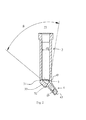
- FIG. 1 shows a capsule 1 according to the invention for receiving and for dispensing highly viscous dental materials.
- the capsule 1 is made of plastic.
- the capsule has a housing 10 which defines an interior space.
- the housing 10 has on the one hand a first opening 11 for pushing in a piston (not shown), on the other hand a second opening 12, which serves as a discharge opening for the exit of the dental material, when the piston is pressed into the interior via the first opening.
- the housing and the interior have a first section 2, a transition region 3 and a second section 4 (outlet nozzle).
- the first section 2 has a first housing section 20, at the first end 21 of which the first opening 11 of the capsule 1 is formed. At the first end of the first housing portion 20, an outwardly extending flange 22 is also formed, which in particular runs in a circle around the edge of the opening 11.
- the interior of the first housing portion 20 is substantially cylindrical with a circular cross-section, constant diameter d1, and a first central longitudinal axis 23. At the second end 24 of the first housing portion 20 immediately follows a first end 31 of the transition region 3.
- the second end 32 of the transition region opens into the second section 4, which is designed as a cylindrical outlet nozzle with a second central longitudinal axis 43.
- the inner diameter d2 of the second section 4 is constant and smaller than the inner diameter d1 of the first section 2. While the first end 41 of the housing 40 directly adjoins the transition region 30, the second end 42 has the outlet opening 12.
- the first central longitudinal axis 23 and the second central longitudinal axis 43 enclose an angle ⁇ of approximately 45 °.
- the interior of the transition region 3 has an inner diameter dt which continuously tapers or reduces towards its second end 32.
- the diameter dt at the first end 31 corresponds to the diameter d1 of the first housing section 20.
- the diameter dt varying along the transitional area 3 corresponds to the inner diameter d2 of the second housing section 40 at the second end 32.
- the taper is continuous and constant (within the transition area 3) Pitch. This means that the interior of the transition region 3 is limited by the lateral surface of a truncated cone.
- the cone corresponding to the truncated cone is an oblique (slate) cone with an opening angle ⁇ , which corresponds to the taper angle.
- the opening angle ⁇ is about 55 ° in the present embodiment.
- the taper is relatively steep, which surprisingly leads to lower extrusion forces in the interior at constant application times and less segregation of the dental material.
- a material thickening 33 in the region of the housing wall, which intersects the first longitudinal axis 23, provides the necessary stability to accommodate the high loads during the discharge of the material.
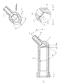
- FIG. 3 is another sectional view.
- the section extends through the outlet nozzle 2 and the transition region 3.
- the interior of the transition region 3 (delimited by the wall 30) opens at a taper angle ⁇ in the outlet channel bounded by the wall 40.
- the flow behavior can be improved while at the same time reducing the tendency for segregation.
- the metering forces can be significantly reduced compared with conventionally used nozzles, ie. H. in the application of lower forces are required, whereby the force during dosing can be reduced.
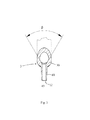
- FIG. 4 shows an embodiment of a plunger / piston 5 according to the invention for dispensing dental material, for example, from a capsule 1 as described above.
- the plunger 5 is inserted through the first opening 11 and pressed in the direction of the outlet nozzle 4 down. Due to the reduction in volume, the residual air initially escapes to the rear, after which the material flows out of the outlet opening 12.
- the plunger 5 is usually made of plastic. It has a base body 50 with an end face 51, which is first inserted into the interior of the capsule.
- the end face 51 forms with the inner wall of the capsule a right angle or the end wall closes with the capsule wall an acute angle of less than 90 °, d. H. There is a negative angle of -10 ° to -30 °. This will clean the material off the wall. Essentially, only the sliding friction between the piston 5 and the inner wall of the cylinder has to be overcome. Adhesive effects or segregation are avoided.
- the resistance can be optimized by coating the piston, in particular in the area of the contact surface / edge 52. Overall, the resistance between the piston and cylinder inner wall is reduced.
- the piston 5 is symmetrical has two outwardly projecting sealing and wiping edges or lips 52, which exert low friction on the walls of the capsule.
- the piston 5 has two sealing and wiping lips.
- FIG. 5 is a plan view of the end face 51 of a piston 5 according to the invention, the piston of the FIG. 4 like.
- the piston 5 in this embodiment (at both sealing lips respectively) three elevations 55, which increase the frictional resistance to the capsule walls by about 3% to 5%. This force is not noticeable in the application, but ensures that the piston is held securely in the capsule and (especially during packaging) is not lost.
- the space between the capsule wall and the sealing edge created by the elevations is so small that although venting is possible, ie, air can enter between the sealing lips, but the dental material can not pass through the gap.
- the capsule is basically like the one in the FIGS. 1 to 3 illustrated and described capsule constructed. Corresponding components are therefore identified by the same reference numerals as in the previous embodiment.
- the angle ⁇ between the first central longitudinal axis 23 and the second central longitudinal axis 43 is approximately 45 °.
- the transition region 3 corresponds to a truncated cone.
- the wall piece 35 is an approximately annular wall portion, preferably with a width of 0.1 mm to 0.25 mm.
- the wall piece 35 is perpendicular to the flow direction or to the longitudinal axis 43 of the second section 4 (outlet nozzle) and acts as a kind of aperture.
- the annular wall section adjoins, on the one hand, the conical region of the transitional region 3 and, on the other hand, the first end 41 of the housing 40 of the second section 4.
- the annular wall portion forming part 44 of the housing 40 forms a kind of projection for the filling material flowing into the outlet nozzle 4.
- the transition edge or flow edge 36 between the annular wall section 35 and the second section 4 is sharp-edged.
- the tapered section of the transitional region 3 has been tilted relative to the first section 2.
- the cone is tilted in the direction of the second longitudinal axis 43.
- the angle ⁇ of the tilt is here 10 °.
- the flow is not affected by the tilt.
- residual material remains in the capsule. In the present embodiment, this residual material can be reduced, since the tilting of the piston can dip deeper into the conical transition region 3. The loss of material in a dispensing operation can thus be reduced by about 30%, wherein the loss of material in the nozzle remains unchanged from the first embodiment.
- FIG. 9 a third embodiment of a piston 5 according to the invention is shown. Unless otherwise described, the piston 5 corresponds to the previously described embodiments. Corresponding components are therefore identified by the same reference numerals as in the previous embodiments.
- the piston 5 has a main body 50 with a front end face 51a and a rear end face 51b.
- the piston 5 is symmetrical with respect to the front and rear portions.
- the end faces 51a and 51b each have a concave projection 510a and 510b, respectively.
- the piston 5 is preferably made of a relatively hard plastic.
- the end faces 51a and 51b are respectively bounded by a circular wiper edge 511a or 511b, which has a radius such that between the inner wall of the capsule and the wiper edge 511a or 511b (at least when the piston is unloaded) a gap, for example from 20 microns to 50 microns wide, is present.
- a gap for example from 20 microns to 50 microns wide.
- the conditions are (as in the boundary layer) so that Auspress practitioner reduced and jamming can be prevented.
- air can escape through the gap (venting).
- the filling material is scraped by the piston 5 from the inner wall of the capsule.
- a transition surface 512a or 512b is arranged between the projection 510a or 510b and the respective edge 511a or 511b.
- This is substantially annular, but runs with a negative slope to the edge 511a and 511b out.
- the surface 512a or 512b in the case of a plan view of the respective end face 51a or 51b, falls toward the edge 511a or 511b, towards the outside. This shows especially clearly the FIG. 10 in which the negative slope of the surface 512a is drawn.
- the angle d is a measure of the slope of the surface 512a toward the outside.
- the angle ⁇ is preferably about 105 ° to 120 °.
- the injection process can be designed so that the cylinder radius decreases in the direction of the longitudinal axis L to the center controlled about 0.2 mm. Ie. the piston has a longitudinally concave cylinder surface. This avoids unwanted jamming of the piston 5 in the capsule.
- FIGS. 11 and 12 show another feature of the third embodiment of the piston 5. This feature may, but need not be, part of the third embodiment.
- projections or ribs 55 are formed at the periphery of the outer jacket wall of the piston 5. These have an overlap with the capsule of about 0.1 mm to 0.2 mm.
- the piston is thus, when it is inserted into the capsule, held in this and can not fall out or be pulled out. Tolerances are reliably compensated by the projections and the piston 5 is held in the capsule with reproducible forces.
- the piston is clamped over the projections 55 with the capsule.
- the forces exerted by it only about 3% to 5% of the extrusion forces, this additional force is not noticeable when deploying for the user.
- the pistons can not be lost because they are held securely in the capsules.
- Three (3) to six (6) ribs can be attached, depending on the capsule and piston material and the behavior of the polymers (filler).
- capsules and pistons act together in different combinations as described above. The result is improved spreading of the filler with lower extrusion forces, higher reliability, and lower requirements for the design of the capsule extrusion dies.
Landscapes
- Health & Medical Sciences (AREA)
- Engineering & Computer Science (AREA)
- Mechanical Engineering (AREA)
- Life Sciences & Earth Sciences (AREA)
- Dentistry (AREA)
- Epidemiology (AREA)
- Oral & Maxillofacial Surgery (AREA)
- Animal Behavior & Ethology (AREA)
- General Health & Medical Sciences (AREA)
- Public Health (AREA)
- Veterinary Medicine (AREA)
- Physics & Mathematics (AREA)
- Geometry (AREA)
- Dental Tools And Instruments Or Auxiliary Dental Instruments (AREA)
- Coating Apparatus (AREA)
Abstract
Description
- Die vorliegende Erfindung betrifft eine Kapsel zur Aufnahme und Dosierung hochviskoser Materialien, beispielsweise von Dentalmaterialien, mit einem Gehäuse, wobei das Gehäuse einen Innenraum begrenzt und eine Öffnung zum Einbringen eines Kolbens und eine Ausbringöffnung aufweist; und wobei das Gehäuse folgende Abschnitte umfasst: einen ersten Gehäuseabschnitt, der einen ersten zylindrischen Innenraumabschnitt begrenzt, wobei der erste Gehäuseabschnitt eine erste zentrale Längsachse, ein erstes Ende und ein zweites Ende aufweist; einen zweiten Gehäuseabschnitt, der eine Austrittsdüse bildet, wobei der zweite Gehäuseabschnitt eine zweite zentrale Längsachse, ein erstes Ende und ein zweites Ende aufweist, und der zweite Gehäuseabschnitt einen Austrittskanal begrenzt, der in die am zweiten Ende ausgebildete Austrittsöffnung mündet; und einen Übergangsabschnitt, dessen erstes Ende mit dem zweiten Ende des ersten Gehäuseabschnitts verbunden ist, und dessen zweites Ende mit dem ersten Ende des zweiten Gehäuseabschnitts verbunden ist; wobei sich die erste zentrale Längsachse und die zweite zentrale Längsachse in einem Winkel α schneiden. Außerdem betrifft die Erfindung einen Kolben, insbesondere zum Ausdrücken von Material aus der genannten Kapsel.
- In verschiedenen Anwendungsgebieten werden hochviskose Materialien eingesetzt, bspw. in der Dentaltechnik. Die Verbundstoffe/ Composite weisen einen hohen Füllanteil und somit hohe Standfestigkeit und Modellierbarkeit auf.
- Die genannten Materialien werden in Einheiten, bspw. in Mengen zwischen 2 g bis 5 g, abgefüllt. Kleinere Mengen, wie etwa 250 mg bis 350mg, werden in standardisierten Einmalverpackungen aus Kunststoff, bspw. in Kapseln oder Tips, abgefüllt.
- Je nach Composit können in der Anwendung in der Kapsel sehr hohe Auspressdrücke und an der Dosierzange sehr große Auspresskräfte entstehen. Während niedrige Auspressdrücke hohe Anwendersicherheit zur Folge haben, da die Kapseln nicht platzen können, sind für Anwender, wie z. B. Zahnärzte, ein langer und schlanker Dosierkanal von Bedeutung, um eine komfortable Anwendung zu gewährleisten. Für eine präzise Handhabung sind geringst mögliche Auspresskräfte vorteilhaft. Zwischen diesen Anforderungen ist eine optimierte Lösung zu finden.
- Ausgehend davon besteht die Aufgabe der vorliegenden Erfindung darin, eine Kapsel und einen Kolben zum Ausbringen von Materialien hoher Viskosität, beispielsweise von Dentalmaterialien, bereitzustellen, wobei das Ausbringen mit verringerten Auspressdrücken und geringer Entmischung des ausgebrachten Materials bei geringen Totvolumina ermöglicht wird.
- Diese Aufgabe wird gelöst durch die Bereitstellung einer Kapsel gemäß dem Anspruch 1 und einem Kolben gemäß dem Anspruch 12 und einer Kombination aus Kapsel und Kolben nach Anspruch 15. Vorteilhafte Ausführungsformen ergeben sich aus den Merkmalen der abhängigen Ansprüche.
- Eine erfindungsgemäße Kapsel zur Aufnahme und Dosierung hochviskoser Materialien umfasst ein Gehäuse, wobei das Gehäuse einen Innenraum begrenzt und eine Öffnung zum Einbringen eines Kolbens und eine Ausbringöffnung aufweist; und wobei das Gehäuse folgende Abschnitte umfasst: einen ersten Gehäuseabschnitt, der einen ersten, insbesondere zylindrischen, Innenraumabschnitt begrenzt, wobei der erste Gehäuseabschnitt eine erste zentrale Längsachse, ein erstes Ende und ein zweites Ende aufweist; einen zweiten Gehäuseabschnitt, der eine Austrittsdüse bildet, wobei der zweite Gehäuseabschnitt eine zweite zentrale Längsachse, ein erstes Ende und ein zweites Ende aufweist, und der zweite Gehäuseabschnitt einen Austrittskanal begrenzt, der in die am zweiten Ende ausgebildete Austrittsöffnung mündet; und einen Übergangsabschnitt, dessen erstes Ende mit dem zweiten Ende des ersten Gehäuseabschnitts verbunden ist, und dessen zweites Ende mit dem ersten Ende des zweiten Gehäuseabschnitts verbunden ist; wobei sich die erste zentrale Längsachse und die zweite zentrale Längsachse in einem Winkel α von 40 bis 50°, vorzugsweise 45° schneiden. Der Übergangsabschnitt verjüngt sich zwischen seinem ersten Ende und seinem zweiten Ende, und der Verjüngungswinkel β beträgt wenigstens 50° bis 90°.
- Durch die vorgeschlagene Geometrie werden die erforderlichen Auspressdrücke verringert, da die Geometrie des Innenraums das Fließverhalten begünstigt. Die Fließwiderstände beim Auspressen vom Dentalmaterialien werden gesenkt. Durch die geringeren Auspressdrücke können die Austrittskanäle im Durchmesser kleiner ausfallen. Das verringert Materialverlust in der Anwendung. Außerdem sinken Zeit- und Kraftaufwand beim Ausbringen der Dentalmaterialien. Die Auspresskraft konnte beispielsweise um 20-30% reduziert werden.
- Als Materialien für die Kapsel kommen Kunststoffe wie PE, insbesondere PA, PBT, POM etc., in Frage.
- Um Verbesserungen zu erzielen, wurde die Innenkontur der Kapseln optimiert. Die Vorteile sind insbesondere auf den relativ steilen Verjüngungswinkel β zurückzuführen. Durch den Übergang reduziert sich außerdem die Neigung der hochviskosen Materialien zur Entmischung. Offensichtlich weisen hochviskose Dentalmaterialien beim Übergang von einem großen Innendurchmesser auf einen kleinen Innendurchmesser mittels eines stumpfen Kegels geringeren Fließwiderstand auf.
- Die Untergrenze für den Verjüngungswinkel, beträgt 50°. Kleinere Winkel verschlechtern die Eigenschaften der Kapsel erheblich. Bei niedrigeren Kegelwinkeln steigt der Fließwiderstand erheblich an.
- Ein weiterer Vorteil der erfindungsgemäßen Geometrie besteht in der einfachen Herstellbarkeit. Ein erster Zylinderkern mit stumpfem Kegelübergang (Kegelstumpf-Übergang) und ein Düsenkern mit rechtwinkliger Kontaktfläche zum Kegelstumpf weisen bei der angegebenen Struktur keine Hinterschneidungen auf. Die Struktur ist somit mit zwei Kernen herstellbar bzw. entformbar.
- Der Winkel α zwischen der ersten zentralen Längsachse und der zweiten zentralen Längsachse beträgt vorzugsweise zwischen 10° und 80°, insbesondere zwischen 30° und 60°, besonders bevorzugt zwischen 40° und 45°.
- Vorzugsweise verjüngt sich der Übergangsabschnitt in Form eines schiefen Kegelstumpfes, wobei der Verjüngungswinkel β dem Öffnungswinkel des Kegels entspricht. Bei schiefen oder schrägen Kegeln befindet sich die Spitze abseits der Lotgeraden durch den Mittelpunkt des Grundkreises. Die Verwendung eines schiefen bzw. schrägen Kegelstumpfes (mit großem Öffnungswinkel) im Übergangsbereich ist durch den Winkel α zwischen der ersten und der zweiten Achse notwendig.
- Der schiefe Kegelstumpf kann gegenüber der ersten zentralen Längsachse verkippt in einem Winkel (γ) angeordnet sein, wobei der Winkel (γ) insbesondere 10° bis 20° beträgt. Dadurch kann ein Kolben tiefer in den Übergangsabschnitt eintauchen, wodurch die Menge des nicht ausbringbaren Materials (Verlustmaterial) verringert wird.
- Insbesondere verbindet der Übergangsabschnitt den ersten Inneraumabschnitt mit dem Austrittskanal, wobei die Übergänge zwischen dem ersten Inneraumabschnitt und dem Innenraum des Übergangsabschnitts bzw. dem Innenraum des Übergangsabschnitts und dem Austrittskanal stetig sein können. In einer weiteren bevorzugten Ausführungsform verbindet der Übergangsabschnitt den ersten Inneraumabschnitt mit dem Austrittskanal, wobei der Übergang zwischen dem Übergangsabschnitt und dem Austrittskanal ein Wandstück aufweist, das quer zur Strömungsrichtung des Füllmaterials angeordnet ist. Auf diese Weise wird eine Strömungskante gebildet.
- Insbesondere kann das Wandstück ringförmig ausgebildet und senkrecht zur zweiten zentralen Längsachse angeordnet sein.
- Der Durchmesser (d) des Innenraums des Übergangsabschnitts nimmt vorzugsweise vom ersten Ende zur äußeren Abgrenzung des Wandstücks hin stetig und mit konstanter Steigung ab.
- Der zweite Gehäuseabschnitt kann sich über das Wandstück an den Übergangsabschnitt anschließen.
- Der Übergang zwischen dem Übergangsabschnitt und dem Austrittskanal kann eine Strömungskante aufweisen. Beim Passieren des Wandabschnitts bzw. an der Strömungskante findet eine mikroskopische Veränderung des Materials statt. Durch die Scherbelastung werden die Molekülketten teilweise "entschlauft" bzw.entflochten und in die Fließrichtung orientiert, d. h. ihre Vernetzung wird gelöst. Dadurch verändert sich die Viskosität in der Grenzschicht und bewirkt ein positives Fließverhalten in der Düse. Nachdem der Fließdruck abgebaut wird verkflechten, verknäulen bzw. verschlaufen sich die Makromoleküle zurück. Eine Entmischung des Füllmaterials nach dem Austritt aus der Düse findet nicht statt. Mit Hilfe der Strömungskante 35 wird eine weitere deutlich messbare Reduzierung und Beruhigung der Auspresskräfte erreicht. Das Fließverhalten ist stetig und kontinuierlich ohne stärkere Variationen der Auspresskraft.
- Der Durchmesser (d1) des ersten Inneraumabschnitts ist insbesondere größer als der Durchmesser (d2) des Austrittskanals. Außen im Bereich des ersten Endes des ersten Gehäuseabschnitts kann ein Flansch ausgebildet sein. Dieser ist in der Regel ringförmig.
- Vorzugsweise nimmt der Durchmesser (d) des Innenraums des Übergangsabschnitts vom ersten Ende zum zweiten Ende hin stetig und mit konstanter Steigung ab. Die Steigung kann aus der Verjüngung des Übergangsbereichs berechnet werden.
- In einer bevorzugten Ausführungsform der Erfindung schließt sich der Übergangsabschnitt unmittelbar an den ersten Gehäuseabschnitt an, und der zweite Gehäuseabschnitt schließt sich unmittelbar oder über das bereits erwähnte quer stehende Wandstück an den Übergangsabschnitt an.
- Die Gehäusewand kann im Bereich des der Übergangsabschnitts verstärkt sein. Für das Auspressen der Materialien aus der Kapsel gibt es auf dem Markt standardisierte Auspresswerkzeuge. Dadurch sind die Außenkontur am Kragen und die Bohrung weitgehend festgelegt. Da immer härtere Materialien ausgebracht werden sollen, werden die Werkzeuge mit immer größeren Übersetzungen angeboten. Dadurch steigt beim Auspressen die Belastung der Kapsel. Typischerweise platzt dabei eine herkömmliche Kapsel im Übergangsbereich zur Düse. Hier entstehen auch die höchsten Kräfte und der Querschnitt ist durch den Austrittskanal geschwächt. Bei der Optimierung des Bodens wurde errechnet, dass eine Verstärkung um ca. 30% bis 50% die Festigkeit ausreichend erhöht. Die Verstärkung ist an der Mantelfläche des Übergangsbereichs vorgesehen.
- Vorzugsweise beträgt der Verjüngungswinkel β zwischen 50° und 120°, insbesondere zwischen 50° und 70°. Stumpfere Winkel wirken sich weniger negativ aus als spitzere Winkel.
- Der Austrittskanal ist vorzugsweise zylindrisch ausgebildet. In einer anderen Ausführungsform kann der Austrittskanal als Konus ausgebildet sein, der sich mit einem Winkel von 1° bis 3° zur Düsenaustrittsöffnung hin öffnet.
- Der erste Durchmesser (d1) ist insbesondere wenigstens doppelt so groß ist wie der zweite Durchmesser (d2). So kann das Verhältnis d1/d2 beispielsweise im Bereich von 2,0-4,0 liegen.
- Eine weitere erfindungsgemäße Kapsel zur Aufnahme und Dosierung hochviskoser Materialien umfasst ein Gehäuse, wobei das Gehäuse einen Innenraum begrenzt und eine Öffnung zum Einbringen eines Kolbens und eine Ausbringöffnung aufweist; und wobei das Gehäuse folgende Abschnitte umfasst: einen ersten Gehäuseabschnitt, der einen ersten, insbesondere zylindrischen, Innenraumabschnitt begrenzt, wobei der erste Gehäuseabschnitt eine erste zentrale Längsachse, ein erstes Ende und ein zweites Ende aufweist; einen zweiten Gehäuseabschnitt, der eine Austrittsdüse bildet, wobei der zweite Gehäuseabschnitt eine zweite zentrale Längsachse, ein erstes Ende und ein zweites Ende aufweist, und der zweite Gehäuseabschnitt einen Austrittskanal begrenzt, der in die am zweiten Ende ausgebildete Austrittsöffnung mündet; und einen Übergangsabschnitt, dessen erstes Ende mit dem zweiten Ende des ersten Gehäuseabschnitts verbunden ist, und dessen zweites Ende mit dem ersten Ende des zweiten Gehäuseabschnitts verbunden ist; wobei sich die erste zentrale Längsachse und die zweite zentrale Längsachse in einem Winkel α von 40 bis 50°, vorzugsweise 45° schneiden. Der Übergang zwischen dem Übergangsabschnitt und dem Austrittskanal weist ein Wandstück auf, das quer zur Strömungsrichtung des Füllmaterials angeordnet ist. Auf diese Weise wird eine Strömungskante gebildet.
- Die Aufgabe wird auch gelöst durch die Bereitstellung eines erfindungsgemäßen Kolbens, der eine dem Austrittskanal zugewandte Stirnseite und eine Abstreifkante bzw. -lippe aufweist, wobei eine Übergangsfläche der Stirnfläche, die an die Abstreifkante angrenzt, mit der Längsachse des Kolbens einen Winkel (δ) von 90° bis 120° einschließt, wobei der Winkel (δ) derart angeordnet ist, dass in der bestimmungsgemäßen Schubrichtung zum Ausbringen des Füllmaterials die Übergangsfläche nach außen hin schräg nach hinten verläuft. Der Begriff "nach außen hin" bezieht sich auf eine Richtung von der Längsachse des Kolbens zu den Innenwänden der Kapsel hin, der Begriff "nach hinten" bedeutet eine Richtung entgegengesetzt zur bestimmungsgemäßen Schubrichtung des Kolbens relativ zur Kapsel zum Ausbringen des Materials. Mit Hilfe des Kolbens wird das Füllmaterial während des Ausbringvorgangs von der Kapselinnenwand abgeschabt, ohne mit dieser zu verkanten.
- Der Winkel (δ) beträgt insbesondere zwischen 105° und 120°.
- An der Abstreifkante bzw. -lippe ist insbesondere wenigstens eine Erhöhung (Vorsprung oder Rippe, die sich vorzugsweise in Längsrichtung des Kolbens erstreckt) ausgebildet.
- Der Kolben kann aus einem teilelastischen Werkstoff hergestellt sein, der sich bei hohem Druck an die Zylinderwandung anpresst. Durch den Druck wird der Kolben so verformt, dass eine für das auszubringende Material ausreichende Dichtigkeit und Stabilität zwischen der Kontaktfläche und der Zylinderinnenwand hergestellt wird. Die Kontaktfläche des Kolbens kann auch beschichtet sein, um die Gleitfähigkeit zu erhöhen.
- In einer besonders bevorzugten Ausführungsform ist der Kolben aus einem relativ steifen und/oder harten Kunststoff hergestellt, um ein Verkanten bzw. Verkeilen mit der Innenwand der Kapsel zu verhindern.
- Der Kolben kann wenigstens eine Abstreiflippe aufweisen, wobei an der Abstreiflippe wenigstens eine Erhöhung ausgebildet ist. Die Erhöhung ist am Außenumfang der Abstreiflippe angeordnet und schafft einen kleinen Zwischenraum zur Entlüftung zwischen der Innenwand der Kapsel und der Abstreiflippe.
- Der Kolben kann symmetrisch sein und zwei Dicht- und Abstreiflippen haben. Die Lippen haben am Umfang jeweils drei Erhöhungen. Dadurch kann zunächst die Luft zwischen Composit und Kolben nach hinten entweichen. Bei Auspressen des Dentalmaterials ist die Kapsel luftfrei.
- Die Aufgabe wird insbesondere auch gelöst durch eine Kombination aus der erfindungsgemäßer Kapsel und dem erfindungsgemäßen Kolben.
- Dabei kann insbesondere zwischen der Abstreifkante und der Innenwand des ersten Abschnitts ein Spalt, beispielsweise von 20 µm bis 50 µm Breite, angeordnet sein. Auf diese Weise ist keine Vorspannung zwischen der Kante 511a bzw. 511b und der Innenwand des Kolbens vorhanden. Zudem kann Luft durch den Spalt entweichen (Entlüftung).
- Die Bildung toter Ecken und Volumina wird bei einer Kombination aus der erfindungsgemäßer Kapsel und dem erfindungsgemäßen Kolben vermieden, da das Volumen des Übergangsbereichs durch den großen Verjüngungswinkel relativ gering ist. Die Restmenge an Material in der Kapsel nach dem Ausbringen (die sich aus dem Restmaterial in den drei Bereichen der Kapsel zusammensetzt) ist als Verlustmenge zu betrachten. Da die auszubringenden Materialien sehr teuer sein können, wird die möglichst geringe Restmenge angestrebt. Der Kolben erfüllt dazu zwei Funktionen, nämlich ein Abstreifen des Dentalmaterials von der Wand und ein möglichst tiefes Eintauchen in den Kegel. Da bei der vorliegenden Kapsel das Volumen des Übergangsbereichs wegen des stumpfen Verjüngungswinkels gering ist, ist auch die Restmenge des darin verbleibenden Materials gering. Die Restmenge wird somit durch die Restmenge in der Düse bestimmt, die durch Düsenlänge und den Düsendurchmesser vorgegeben ist.
- Es muss zudem im Rahmen der Erfindung kein kegelartiger Kolben verwendet werden, um das Material möglichst vollständig aus der Kapsel auszubringen. Die Verwendung kegelartiger Kolben mit kegelförmiger Stirnfläche führt nämlich dazu, dass sich Material zwischen der Innenwand der Kapsel und dem Kolben sammeln und dort verkleben kann. Die Kombination aus erfindungsgemäßer Kapsel und erfindungsgemäßem Kolben ist daher auch in Bezug auf die Vermeidung von zusätzlicher Reibung beim Ausbringen vorteilhaft.
- Insgesamt wird ein geringerer Widerstand zwischen Kolben und Zylinder erreicht. Zu den in der Kapsel beim Dosieren entstehenden sehr hohen Drücken bzw. Fließkräften addiert sich der Widerstand zwischen Kolben und Kapsel. Beim Auspressen des Materials muss der gesamte Widerstand überwunden werden. Dieser kann bei ungünstigen Formen sehr hoch sein. Übliche Kolben mit steiler, kegelartiger Stirnfläche können sehr hohe Reibkräfte bewirken, da sich das Material zwischen dem Kolbenkegel und der Zylinderwand verkeilt. Dabei kann es zu einer Entmischung kommen. Dies reduziert zum einen die Qualität des Produktes, zum anderen verklebt der Kolben in der Kapsel.
- Wie beschrieben werden die Nachteile durch die erfindungsgemäße Kombination überwunden. Die Stirnfläche des Kolbens bildet im Kontaktbereich zur Kapselinnenwand einen rechten Winkel oder einen negativen Winkel, beispielsweise von -10° bis -30°. Dies bedeutet, dass sich zwischen der Kapselwand und dem Kolben ein spitzer Winkel kleiner als 90° ausbildet. Der Randbereich der Kolbenstirnwand verläuft, bezogen auf die Ausbringrichtung, nach hinten schräg. Dadurch wird das Material sauber von der Wand abgestreift. Es muss lediglich die Gleitreibung zwischen Kolben und Zylinder überwunden werden. Klebeeffekte oder Entmischung treten nicht auf. Der Widerstand kann durch die Verwendung geeigneter Materialien für Kapsel und Kolben und/oder durch eine Beschichtung des Kolbens, wenigstens im Kontaktbereich, optimiert werden. Als Beschichtung kommen beispielsweise Teflondispersion oder eine Teflonbeimischung in das Kolbenmaterial in Frage.
- Schutz soll auch für ein Herstellungsverfahren zur Herstellung einer Kapsel und/oder eines Kolbens wie oben beschrieben beansprucht werden. Die Teile werden in einem Spritzgussverfahren gefertigt, wobei bei der Kapselherstellung zwei Kerne verwendet werden, nämlich ein erster Kern für die zylindrische Austrittsdüse und ein zweiter Kern für den ersten Innenraumabschnitt und den Kegelstumpfartigen Übergangsbereich. Die Machbarkeit wird dadurch sichergestellt, dass keine Hinterspritzung zwischen den zwei Kernen vorhanden ist. Die Kerne stoßen ohne Hinterschnitt im rechten Winken aufeinander. Querkräfte treten nicht auf. Eine Toleranzverschiebung wird dadurch zugelassen, dass im Übergangsbereich der Durchmesser des Kegelschnitts (zweites Ende des Übergangsbereichs) um einen vorbestimmten Betrag (z. B. 0,2 mm bis 0,5 mm) größer gefertigt wird als der Durchmesser der Austrittsdüse.
- Für die beschriebenen Merkmale soll in allen möglichen neuen Kombinationen Schutz beansprucht werden.
- Weitere Merkmale und Vorteile der Erfindung werden aus der nachfolgenden Beschreibung eines bevorzugten Ausführungsbeispiels anhand der beigefügten Figuren deutlich. Die Figuren zeigen:
- Figur 1
- eine Draufsicht auf eine erste Ausführungsform einer erfindungsgemäßen Kapsel;
- Figur 2
- eine erste Schnittansicht der erfindungsgemäßen Kapsel aus
Figur 1 ; - Figur 3
- eine zweite Schnittansicht der erfindungsgemäßen Kapsel aus
Figur 1 ; - Figur 4
- einen perspektivische Ansicht einer ersten Ausführungsform eines erfindungsgemäßen Kolbens;
- Figur 5
- eine Draufsicht auf die Stirnfläche einer zweiten Ausführungsform eines erfindungsgemäßen Kolbens;
- Figur 6
- eine erste Schnittansicht einer zweite Ausführungsform einer erfindungsgemäßen Kapsel;
- Figur 7
- eine zweite Schnittansicht der erfindungsgemäßen Kapsel aus
Figur 6 ; - Figur 8
- ein Detail der erfindungsgemäßen Kapsel aus
Figur 6 ; - Figur 9
- einen perspektivische Längsansicht einer dritten Ausführungsform eines erfindungsgemäßen Kolbens;
- Figur 10
- ein Längsschnitt durch den Kolben aus
Figur 9 ; - Figur 11
- eine vordere Draufsicht auf den Kolben aus
Figur 9 ; und - Figur 12
- ein Detail aus
Figur 11 . - Die beigefügte
Figur 1 zeigt eine erfindungsgemäße Kapsel 1 zur Aufnahme und zum Ausbringen hochviskoser Dentalmaterialien. Die Kapsel 1 ist aus Kunststoff hergestellt. - Die Kapsel weist ein Gehäuse 10 auf, das einen Innenraum begrenzt. Das Gehäuse 10 weist zum einen eine erste Öffnung 11 zum Eindrücken eines Kolbens (nicht dargestellt) auf, zum anderen eine zweite Öffnung 12, die als Ausbringöffnung zum Austritt des Dentalmaterials dient, wenn der Kolben über die erste Öffnung in den Innenraum gepresst wird.
- Das Gehäuse und der Innenraum weisen einen ersten Abschnitt 2, einen Übergangsbereich 3 und einen zweiten Abschnitt 4 (Austrittsdüse) auf.
- Der erste Abschnitt 2 weist einen ersten Gehäuseabschnitt 20 auf, an dessen ersten Ende 21 die erste Öffnung 11 der Kapsel 1 ausgebildet ist. Am ersten Ende des ersten Gehäuseabschnitts 20 ist außerdem ein sich nach außen erstreckender Flansch 22 ausgebildet, der insbesondere kreisförmig um den Rand der Öffnung 11 verläuft. Der Innenraum des ersten Gehäuseabschnitts 20 ist im Wesentlichen zylindrisch mit kreisförmigem Querschnitt, konstantem Durchmesser d1, und einer ersten zentralen Längsachse 23. An das zweite Ende 24 des ersten Gehäuseabschnitts 20 schließt sich unmittelbar ein erstes Ende 31 des Übergangsbereichs 3 an.
- Das zweite Ende 32 des Übergangsbereichs mündet in den zweiten Abschnitt 4, der als zylindrische Austrittsdüse mit einer zweiten zentralen Längsachse 43 konzipiert ist. Der Innendurchmesser d2 des zweiten Abschnitts 4 ist konstant und kleiner als der Innendurchmesser d1 des ersten Abschnitts 2. Während sich das erste Ende 41 des Gehäuses 40 unmittelbar an den Übergangsbereich 30 anschließt, weist das zweite Ende 42 die Austrittsöffnung 12 auf.
- Die erste zentrale Längsachse 23 und die zweite zentrale Längsachse 43 schließen einen Winkel α von ca. 45° ein.
- Wie aus der
Figur 2 hervorgeht, weist der Innenraum des Übergangsbereichs 3 einen Innendurchmesser dt auf, der sich zu seinem zweiten Ende 32 hin stetig verjüngt bzw. verringert. Der Durchmesser dt am ersten Ende 31 entspricht dem Durchmesser d1 des ersten Gehäuseabschnitts 20. Der entlang des Übergangsbereichs 3 variierende Durchmesser dt entspricht am zweiten Ende 32 dem Innendurchmesser d2 des zweiten Gehäuseabschnitts 40. Die Verjüngung erfolgt stetig und (innerhalb des Übergangsbereichs 3) mit konstanter Steigung. Dies bedeutet, dass der Innenraum des Übergangsbereichs 3 durch die Mantelfläche eines Kegelstumpfes begrenzt wird. Der dem Kegelstumpf entsprechende Kegel ist ein schräger (schiefer) Kegel mit einem Öffnungswinkel β, der dem Verjüngungswinkel entspricht. Der Öffnungswinkel β beträgt im vorliegenden Ausführungsbeispiel ca. 55°. Damit ist die Verjüngung relativ steil, was überraschend zu geringeren Auspresskräften im Innenraum bei konstanten Ausbringzeiten und zu geringerer Entmischung des Dentalmaterials führt. - An der bei 32 angedeuteten Linie stoßen die beiden bei der Herstellung im Spritzguss verwendeten Kerne aneinander.
- Eine Materialverdickung 33 im Bereich der Gehäusewand, die die erste Längsachse 23 schneidet, sorgt für die nötige Stabilität, um die hohen Belastungen während des Ausbringens des Materials aufzunehmen.
- Die
Figur 3 ist eine weitere Schnittdarstellung. Der Schnitt erstreckt sich durch die Austrittsdüse 2 sowie den Übergangsbereich 3. Der Innenraum des Übergangsbereichs 3 (begrenzt durch die Wand 30) mündet mit einem Verjüngungswinkel β in den durch die Wand 40 begrenzten Austrittskanal. - Mittels der Erfindung kann das Fließverhalten bei gleichzeitig reduzierter Neigung zum Entmischen verbessert werden. Dies führt dazu, dass beim Dosieren hochviskoser Materialien die Dosierkräfte gegenüber herkömmlich verwendeten Düsen erheblich gesenkt werden können, d. h. in der Anwendung sind geringere Kräfte erforderlich, wodurch die Kraft beim Dosieren verringert werden kann.
- Die
Figur 4 zeigt eine Ausführungsform eines erfindungsgemäßen Stößels/Kolbens 5 zum Ausbringen von Dentalmaterial beispielsweise aus einer Kapsel 1 wie oben beschrieben. Dazu wird der Stößel 5 durch die erste Öffnung 11 eingeführt und in Richtung der Austrittsdüse 4 nach unten gepresst. Durch die Volumenreduzierung entweicht zunächst die Restluft nach hinten, danach fließt das Material aus der Austrittsöffnung 12 aus. - Der Stößel 5 ist in der Regel aus Kunststoff hergestellt. Er weist einen Grundkörper 50 mit einer Stirnfläche 51 auf, die zuerst in den Innenraum der Kapsel eingeführt wird. Die Stirnfläche 51 bildet mit der Innenwand der Kapsel einen rechten Winkel bzw. die Stirnwand schließt mit der Kapselwand einen spitzen Winkel kleiner 90° ein, d. h. es ist ein negativer Winkel von -10° bis -30° vorhanden. Dadurch wird das Material sauber von der Wand abgestreift. Es muss im Wesentlichen nur die Gleitreibung zwischen dem Kolben 5 und der Innenwand des Zylinders überwunden werden. Klebeeffekte oder Entmischung werden vermieden. Der Widerstand kann durch Beschichtung des Kolbens, insbesondere im Bereich der Kontaktfläche/-kante 52, optimiert werden. Insgesamt wird der Widerstand zwischen Kolben und Zylinderinnenwand reduziert.
- Beim automatischen Einbringen des Kolbens 5 durch die Kapselöffnung 11 und beim Auspressen der Materialien muss Luft aus dem eingeschlossenen Innenraum der Kapsel nach hinten entweichen können. Das auszubringende Material darf dabei nicht nach hinten in Richtung der ersten Öffnung 11 entweichen, da eine Kontamination des Stößels der Auspresszange zu vermeiden ist. Aus diesem Grund ist der Kolbenkörper 50 mit einem Entlüftungsspalt 53 ausgebildet. Dieser ist groß genug, sodass Luft sicher entweichen kann, allerdings nicht durchlässig für das auszubringende hochviskose Material.
- Insgesamt ist der Kolben 5 symmetrisch weist zwei noch außen hervorstehende Dicht- und Abstreifkanten bzw. -lippen 52 auf, die geringe Reibung auf die Wände der Kapsel ausüben. Der Kolben 5 hat zwei Dicht- und Abstreiflippen.
- Die
Figur 5 ist eine Draufsicht auf die Stirnfläche 51 eines erfindungsgemäßen Kolbens 5, der dem Kolben aus derFigur 4 gleicht. Zusätzlich weist der Kolben 5 bei dieser Ausführungsform (an beiden Dichtlippen jeweils) drei Erhöhungen 55 auf, die den Reibwiderstand zu den Kapselwänden um ca. 3% bis 5 % erhöhen. Diese Kraft ist in der Anwendung nicht spürbar, sorgt aber dafür, dass der Kolben sicher in der Kapsel gehalten wird und (insbesondere beim Verpacken) nicht verloren geht. Allerdings ist der durch die Erhöhungen entstehende Zwischenraum zwischen Kapselwand und Dichtkante so klein, dass zwar eine Entlüftung möglich ist, d. h. Luft zwischen die Dichtlippen treten kann, das Dentalmaterial jedoch nicht durch den Spalt hindurch treten kann. - Eine weitere Reduktion der Auspresskräfte gelingt mit einer Variation der erfindungsgemäßen Kapsel gemäß den
Figuren 6, 7 und 8 . - Die Kapsel ist prinzipiell wie die in den
Figuren 1 bis 3 dargestellte und beschriebene Kapsel aufgebaut. Entsprechende Komponenten sind daher mit denselben Bezugszeichen wie im vorherigen Ausführungsbeispiel gekennzeichnet. - Der Winkel α zwischen der ersten zentralen Längsachse 23 und der zweiten zentralen Längsachse 43 beträgt ca. 45°. Der Übergangsbereich 3 entspricht einem Kegelstumpf. Ein entsprechender schräger (schiefer) Kegel weist einen Öffnungswinkel β = 55° auf der dem Verjüngungswinkel entspricht.
- Am Übergang 34 zwischen dem Übergangsbereich 3 und der Austrittsdüse 2, der in der Detaildarstellung gemäß
Figur 8 besonders deutlich erkennbar ist, weist ein Wandstück 35 auf. Das Wandstück 35 ist ein in etwa ringförmiger Wandabschnitt, vorzugsweise mit einer Breite von 0,1 mm bis 0,25 mm. Das Wandstück 35 liegt senkrecht zur Flussrichtung bzw. zur Längsachse 43 des zweiten Abschnitts 4 (Austrittsdüse) und wirkt als eine Art Blende. Der ringförmige Wandabschnitt schließt sich einerseits an den kegelförmigen Bereich des Übergangsbereichs 3 und andererseits an das erste Ende 41 des Gehäuses 40 des zweiten Abschnitts 4 an. Der den ringförmige Wandabschnitt bildende Teil 44 des Gehäuses 40 bildet eine Art Vorsprung für das in die Austrittsdüse 4 fließende Füllmaterial. Die Übergangskante bzw. Strömungskante 36 zwischen dem ringförmigen Wandabschnitt 35 und dem zweiten Abschnitt 4 ist scharfkantig. - Beim Passieren des Wandabschnitts 35 bzw. an der Strömungskante 36 findet eine mikroskopische Veränderung des Materials statt. Durch die Scherbelastung werden die Molekülketten teilweise "entschlauft" und in die Fliessrichtung orientiert, d. h. ihre Vernetzung wird gelöst. Dadurch verändert sich die Viskosität in der Grenzschicht und bewirkt ein positives Fließverhalten in der Düse. Nachdem der Fließdruck abgebaut wird verknäulen und verschlaufen sich die Makromoleküle zurück. Eine Entmischung des Füllmaterials nach dem Austritt aus der Düse findet nicht statt. Mit Hilfe der Strömungskante 35 wird eine weitere deutlich messbare Reduzierung und Beruhigung der Auspresskräfte erreicht. Die Kräfte unterliegen keinen größeren Schwankungen, d. h. die Kurve ist stetig. Das Fließverhalten ist stetig und kontinuierlich ohne stärkere Variationen der Auspresskraft.
- Als weitere Abwandlung gegenüber der ersten Ausführungsform besteht darin, dass der kegelförmige Abschnitt des Übergangsbereichs 3 gegenüber dem ersten Abschnitt 2 verkippt wurde. In diesem Ausführungsbeispiel ist der Kegel in Richtung der zweiten Längsachse 43 verkippt. Der Winkel γ der Verkippung beträgt hier 10°. Die Strömung wird durch die Verkippung nicht beeinflusst. Bei jeder der Ausführungsformen bleibt beim Auspressen, in Abhängigkeit von der Kolbenform und vom Kegelstumpf, Restmaterial in der Kapsel. In der vorliegenden Ausführungsform kann dieses Restmaterial reduziert werden, da durch die Verkippung der Kolben tiefer in den kegelförmigen Übergangsbereich 3 eintauchen kann. Der Materialverlust bei einem Ausbringvorgang kann so um ca. 30 % verringert werden, wobei der Materialverlust in der Düse gegenüber der ersten Ausführungsform unverändert bleibt.
- In der
Figur 9 ist eine dritte Ausführungsform eines erfindungsgemäßen Kolbens 5 dargestellt. Soweit nichts anderes beschrieben ist, entspricht der Kolben 5 den vorher beschriebenen Ausführungsformen. Entsprechende Komponenten sind daher mit denselben Bezugszeichen wie in den vorherigen Ausführungsbeispielen gekennzeichnet. - Der Kolben 5 weist einen Grundkörper 50 mit einer vorderseitigen Stirnfläche 51a und einer rückseitigen Stirnfläche 51b auf. Der Kolben 5 ist hinsichtlich des vorderen und hinteren Bereichs symmetrisch aufgebaut. Die Stirnflächen 51a und 51b weisen jeweils einen konkaven Vorsprung 510a bzw. 510b auf.
- Der Kolben 5 ist vorzugsweise aus einem relativ harten Kunststoff hergestellt. Im Gegensatz zu der ersten und zweiten Ausführungsform werden die Stirnflächen 51a und 51b jeweils durch eine kreisförmige Abstreifkante 511a bzw. 511b begrenzt, die einen Radius derart aufweist, dass zwischen der Innenwand der Kapsel und der Abstreifkante 511a bzw. 511b (zumindest bei unbelastetem Kolben) ein Spalt, beispielsweise von 20 µm bis 50 µm Breite, vorhanden ist. Auf diese Weise ist auch keine Vorspannung zwischen der Kante 511a bzw. 511b und der Innenwand des Kolbens vorhanden. Die Verhältnisse sind (ähnlich wie in der Grenzschicht) so, dass Auspresskräfte reduziert und ein Verklemmen verhindert werden. Zudem kann Luft durch den Spalt entweichen (Entlüftung). Das Füllmaterial wird durch den Kolben 5 von der Innenwand der Kapsel abgeschabt.
- Zwischen dem Vorsprung 510a bzw. 510b und der jeweiligen Kante 511a bzw. 511b ist eine Übergangsfläche 512a bzw. 512b angeordnet. Diese ist im Wesentlichen ringförmig, verläuft jedoch mit negativer Steigung zur Kante 511a bzw. 511b hin. D. h. die Fläche 512a bzw. 512b fällt, bei Draufsicht auf die jeweilige Stirnseite 51a bzw. 51b, zur Kante 511a bzw. 511b, nach außen hin, ab. Dies zeigt besonders deutlich die
Figur 10 , in der die negative Steigung der Fläche 512a eingezeichnet ist. Der Winkel d ist ein Maß für die Steigung bzw. das Gefälle der Fläche 512a nach außen hin. Der Winkel δ beträgt vorzugsweise etwa 105° bis 120°. - Aus der
Figur 10 wird ein weiteres Merkmal des Kolbens 5 deutlich. Durch das Schwindverhalten der Kunststoffe kann der Spritzprozess so gestaltet werden, dass der Zylinderradius in Richtung der Längsachse L zur Mitte hin kontrolliert ca. 0,2 mm abnimmt. D. h. der Kolben weist eine in Längsrichtung konkave Zylinderoberfläche auf. Dadurch wird ein unerwünschtes Verklemmen des Kolbens 5 in der Kapsel vermieden. - Die
Figuren 11 und 12 zeigen ein weiteres Merkmal der dritten Ausführungsform des Kolbens 5. Dieses Merkmal kann, muss jedoch nicht Teil der dritten Ausführungsform sein. - Am Umfang der äußeren Mantelwand des Kolbens 5 sind Vorsprünge bzw. Rippen 55 ausgebildet. Diese haben eine Überdeckung mit der Kapsel von ca. 0,1 mm bis 0,2 mm. Der Kolben wird somit, wenn er in die Kapsel eingebracht ist, in dieser festgehalten und kann nicht herausfallen bzw. herausgezogen werden. Durch die Vorsprünge werden Toleranzen sicher kompensiert und der Kolben 5 mit reproduzierbaren Kräften in der Kapsel gehalten. Der Kolben ist über die Vorsprünge 55 mit der Kapsel verspannt. Da die dadurch ausgeübten Kräfte jedoch nur ca. 3 % bis 5 % der Auspresskräfte betragen, ist diese Zusatzkraft beim Ausbringen für den Benutzer nicht wahrnehmbar. Beim Transport oder Verpacken können andererseits die Kolben nicht verloren gehen, da sie sicher in den Kapseln gehalten werden.
- Es können drei (3) bis sechs (6) Rippen angebracht werden, abhängig vom Kapsel- und Kolbenwerkstoff und dem Verhalten der Polymere (Füllmaterial).
- Wenn auch nicht in einer Figur dargestellt wirken Kapseln und Kolben wie oben beschrieben in unterschiedlichen Kombinationen zusammen. Das Ergebnis ist ein verbessertes Ausbringen des Füllmaterials mit geringeren Auspresskräften, höherer Zuverlässigkeit und geringeren Anforderungen an die Bauweise der Kapsel - Auspresswerkzeuge.
Claims (15)
- Kapsel (1) zur Aufnahme und Dosierung hochviskoser Materialien, mit einem Gehäuse, wobei
das Gehäuse einen Innenraum begrenzt und eine Öffnung (11) zum Einbringen eines Kolbens und eine Ausbringöffnung (12) aufweist; und
wobei das Gehäuse folgende Abschnitte umfasst:einen ersten Gehäuseabschnitt (20), der einen ersten Innenraumabschnitt begrenzt, wobei der erste Gehäuseabschnitt (20) eine erste zentrale Längsachse (23), ein erstes Ende (21) und ein zweites Ende (24) aufweist;einen zweiten Gehäuseabschnitt (40), der eine Austrittsdüse bildet, wobei der zweite Gehäuseabschnitt (40) eine zweite zentrale Längsachse (43), ein erstes Ende (41) und ein zweites Ende (42) aufweist, und der zweite Gehäuseabschnitt (40) einen Austrittskanal begrenzt, der in die am zweiten Ende (42) ausgebildete Austrittsöffnung (12) mündet; undeinen Übergangsabschnitt (3), dessen erstes Ende (31) mit dem zweiten Ende (24) des ersten Gehäuseabschnitts (20) verbunden ist, und dessen zweites Ende (32) mit dem ersten Ende (41) des zweiten Gehäuseabschnitts (40) verbunden ist;wobei sich die erste zentrale Längsachse (23) und die zweite zentrale Längsachse (43) in einem Winkel (α) schneiden,dadurch gekennzeichnet, dass
sich der Übergangsabschnitt (3) zwischen seinem ersten Ende (31) und seinem zweiten Ende (32) verjüngt, und der Verjüngungswinkel (β) wenigstens 50° beträgt. - Kapsel (1) nach Anspruch 1,
dadurch gekennzeichnet, dass
sich der Übergangsabschnitt (3) in Form eines schiefen Kegelstumpfes verjüngt, wobei der Verjüngungswinkel (β) dem Öffnungswinkel des Kegels entspricht. - Kapsel (1) nach Anspruch 2,
dadurch gekennzeichnet, dass
der schiefe Kegelstumpf gegenüber der ersten zentralen Längsachse (23) verkippt in einem Winkel (γ) angeordnet ist, wobei der Winkel (γ) insbesondere 10° bis 20° beträgt. - Kapsel (1) nach einem der vorhergehenden Ansprüche,
dadurch gekennzeichnet, dass
der Übergangsabschnitt (3) den ersten Inneraumabschnitt mit dem Austrittskanal verbindet, wobei der Übergang (34) zwischen dem Übergangsabschnitt (3) und dem Austrittskanal (4) ein Wandstück (35) aufweist, das quer zur Strömungsrichtung des Füllmaterials angeordnet ist. - Kapsel (1) nach Anspruch 4,
dadurch gekennzeichnet, dass
das Wandstück (35) ringförmig ausgebildet und senkrecht zur zweiten zentralen Längsachse (43) angeordnet ist. - Kapsel (1) nach Anspruch 4 oder 5,
dadurch gekennzeichnet, dass
der Durchmesser (d) des Innenraums des Übergangsabschnitts (3) vom ersten Ende (31) zur äußeren Abgrenzung des Wandstücks (35) hin stetig und mit konstanter Steigung abnimmt. - Kapsel (1) nach einem der Ansprüche 4 bis 6,
dadurch gekennzeichnet, dass
sich der zweite Gehäuseabschnitt (40) über das Wandstück (35) an den Übergangsabschnitt (3) anschließt. - Kapsel (1) nach einem der vorhergehenden Ansprüche,
dadurch gekennzeichnet, dass
der Übergang (34) zwischen dem Übergangsabschnitt (3) und dem Austrittskanal (4) eine Strömungskante (36) aufweist. - Kapsel (1) nach einem der vorhergehenden Ansprüche,
dadurch gekennzeichnet, dass
der Austrittskanal des zweiten Gehäuseabschnitts (40) konusförmig ausgebildet ist und sich mit einem Winkel, insbesondere in einem Winkel von 1° bis 3°, zur Austrittsöffnung (12) hin öffnet. - Kapsel (1) nach einem der vorhergehenden Ansprüche,
dadurch gekennzeichnet, dass
der Durchmesser (d) des Innenraums des Übergangsabschnitts (3) vom ersten Ende (31) zum zweiten Ende (32) hin stetig und mit konstanter Steigung abnimmt. - Kapsel (1) nach einem der vorhergehenden Ansprüche,
dadurch gekennzeichnet, dass
dass der Verjüngungswinkel (β) zwischen 50° und 120°, insbesondere zwischen 50° und 70°, beträgt. - Kolben (50), insbesondere zum Ausdrücken von Material aus einer Kapsel (1) gemäß einem der vorhergehenden Ansprüche,
dadurch gekennzeichnet, dass
der Kolben (50) wenigstens eine Stirnseite (51) und eine Abstreifkante bzw. -lippe (52; 511a, 511b) aufweist, wobei eine Übergangsfläche (512a, 512b) der Stirnfläche (51), die an die Abstreifkante angrenzt, mit der Längsachse (L) des Kolbens (50) einen Winkel (δ) von 90° bis 120° einschließt, wobei der Winkel (δ) derart angeordnet ist, dass in der bestimmungsgemäßen Schubrichtung zum Ausbringen des Füllmaterials die Übergangsfläche (512a, 512b) nach außen hin schräg nach hinten verläuft. - Kolben (50) nach Anspruch 12,
dadurch gekennzeichnet, dass
der Winkel (δ) zwischen 105° und 120° beträgt. - Kolben (50) nach Anspruch 12 oder 13,
dadurch gekennzeichnet, dass
an der Abstreifkante bzw. -lippe (52; 511a, 511b) wenigstens eine Erhöhung (55) ausgebildet ist. - Kombination aus einer Kapsel nach einem der Ansprüche 1 bis 11 und einem Kolben nach einem der Ansprüche 12 bis 14, wobei insbesondere zwischen der Abstreifkante (511a, 511b) und der Innenwand des ersten Abschnitts (2) ein Spalt angeordnet ist.
Applications Claiming Priority (1)
| Application Number | Priority Date | Filing Date | Title |
|---|---|---|---|
| DE102010036782A DE102010036782A1 (de) | 2010-07-30 | 2010-07-30 | Kapsel und Kolben |
Publications (3)
| Publication Number | Publication Date |
|---|---|
| EP2412448A2 true EP2412448A2 (de) | 2012-02-01 |
| EP2412448A3 EP2412448A3 (de) | 2016-03-16 |
| EP2412448B1 EP2412448B1 (de) | 2017-09-06 |
Family
ID=44653983
Family Applications (1)
| Application Number | Title | Priority Date | Filing Date |
|---|---|---|---|
| EP11174826.5A Active EP2412448B1 (de) | 2010-07-30 | 2011-07-21 | Kapsel und Kolben |
Country Status (4)
| Country | Link |
|---|---|
| US (1) | US8684731B2 (de) |
| EP (1) | EP2412448B1 (de) |
| JP (1) | JP2012071110A (de) |
| DE (2) | DE102010036782A1 (de) |
Cited By (3)
| Publication number | Priority date | Publication date | Assignee | Title |
|---|---|---|---|---|
| WO2020025485A1 (de) | 2018-07-31 | 2020-02-06 | Voco Gmbh | Vorrichtung zur aufnahme und applikation von dentalmaterial und verfahren |
| DE102018126140A1 (de) | 2018-10-22 | 2020-04-23 | Voco Gmbh | Vorrichtung mit einem thermochromen Temperaturindikator zur Aufnahme, Erwärmung und Applikation von Dentalmaterialien |
| DE102021103980A1 (de) | 2021-02-19 | 2022-08-25 | Universität Rostock, Körperschaft des öffentlichen Rechts | Anordnung zur Aufnahme und/oder Applikation eines Dentalkomposits |
Families Citing this family (5)
| Publication number | Priority date | Publication date | Assignee | Title |
|---|---|---|---|---|
| DE102009017980B4 (de) * | 2009-04-21 | 2012-12-06 | Heraeus Kulzer Gmbh | Kunststoffkapsel zum Lagern und Ausbringen von fließfähigen Dentalwerkstoffen sowie deren Verwendung |
| DE102010060308A1 (de) * | 2010-11-02 | 2012-05-03 | Transcodent GmbH & Co. KG | Vorrichtung und Verfahren zur Mehrfachabfüllung hochviskoser Materialien |
| JP6253938B2 (ja) * | 2013-09-30 | 2017-12-27 | 株式会社松風 | 環状接触するピストンを有する粘性材料収容容器 |
| JP6274804B2 (ja) | 2013-09-30 | 2018-02-07 | 株式会社松風 | 屈曲部が拡張する粘性材料収容容器 |
| JP6635698B2 (ja) * | 2015-07-14 | 2020-01-29 | ぺんてる株式会社 | 抵抗構造によりプランジャの可動範囲を制限したアプリケータ |
Family Cites Families (15)
| Publication number | Priority date | Publication date | Assignee | Title |
|---|---|---|---|---|
| US2381785A (en) * | 1941-12-15 | 1945-08-07 | Morris J Thompson | Dental hydrocolloid syringe |
| DE3148490C2 (de) * | 1981-12-08 | 1986-02-13 | Alfred Fischbach Kg Kunststoff-Spritzgusswerk, 5250 Engelskirchen | Bodenverschluß für einen hohlzylindrischen Strangpreßbehälter |
| US5083921A (en) * | 1989-02-06 | 1992-01-28 | Dragan William B | Dental syringe tip |
| US4963093A (en) * | 1989-02-06 | 1990-10-16 | Dragan William B | Dental syringe tip and syringe holder therefor |
| US5122057A (en) * | 1991-01-07 | 1992-06-16 | Centrix, Inc. | Dosing dental cartridge |
| US5172807A (en) * | 1991-09-30 | 1992-12-22 | Centrix, Inc. | Cement mixing capsule |
| US5322440A (en) * | 1992-10-20 | 1994-06-21 | Kerr Manufacturing Company | Dental syringe tip |
| US5460523A (en) * | 1994-07-14 | 1995-10-24 | Jeneric/Pentron | Dental composite cartridge |
| DE19651981C1 (de) * | 1996-12-13 | 1998-07-23 | Ivoclar Ag | Spritze für viskose Massen und Verfahren zur Herstellung einer Spritze für viskose Massen |
| DE19700480A1 (de) * | 1997-01-09 | 1998-07-16 | Saremco Ag | Dentalpatrone |
| US6503084B2 (en) * | 2000-02-24 | 2003-01-07 | Dentsply Detrey G.M.B.H. | Method for dispensing dental materials |
| US6379152B1 (en) * | 2000-04-19 | 2002-04-30 | Centrix, Inc. | Dental capsule for placement of ultra-high viscosity dental composite material |
| AU2003200509A1 (en) * | 2002-02-27 | 2003-09-11 | Centrix, Inc | Dental capsule for placement of high viscosity dental composite material with reduced extrusion force |
| US20030196914A1 (en) * | 2002-04-18 | 2003-10-23 | 3M Innovative Properties Company | Containers for photocurable materials |
| DE10218859B4 (de) | 2002-04-26 | 2006-05-24 | Heraeus Kulzer Gmbh | Kapsel aus Kunststoff zur Aufbewahrung und Abgabe von Dentalmaterial |
-
2010
- 2010-07-30 DE DE102010036782A patent/DE102010036782A1/de not_active Withdrawn
- 2010-07-30 DE DE202010015594U patent/DE202010015594U1/de not_active Expired - Lifetime
-
2011
- 2011-07-21 EP EP11174826.5A patent/EP2412448B1/de active Active
- 2011-07-28 JP JP2011165440A patent/JP2012071110A/ja active Pending
- 2011-08-01 US US13/195,339 patent/US8684731B2/en active Active
Non-Patent Citations (1)
| Title |
|---|
| None |
Cited By (6)
| Publication number | Priority date | Publication date | Assignee | Title |
|---|---|---|---|---|
| WO2020025485A1 (de) | 2018-07-31 | 2020-02-06 | Voco Gmbh | Vorrichtung zur aufnahme und applikation von dentalmaterial und verfahren |
| US11730566B2 (en) | 2018-07-31 | 2023-08-22 | Voco Gmbh | Device for storage and application and method |
| DE102018126140A1 (de) | 2018-10-22 | 2020-04-23 | Voco Gmbh | Vorrichtung mit einem thermochromen Temperaturindikator zur Aufnahme, Erwärmung und Applikation von Dentalmaterialien |
| EP3643270A1 (de) | 2018-10-22 | 2020-04-29 | VOCO GmbH | Vorrichtung mit einem thermochromen temperaturindikator zur aufnahme, erwärmung und applikation von dentalmaterialien |
| DE102018126140B4 (de) | 2018-10-22 | 2023-12-07 | Voco Gmbh | Vorrichtung mit einem thermochromen Temperaturindikator zur Aufnahme, Erwärmung und Applikation von Dentalmaterialien |
| DE102021103980A1 (de) | 2021-02-19 | 2022-08-25 | Universität Rostock, Körperschaft des öffentlichen Rechts | Anordnung zur Aufnahme und/oder Applikation eines Dentalkomposits |
Also Published As
| Publication number | Publication date |
|---|---|
| DE102010036782A1 (de) | 2012-02-02 |
| US20120028217A1 (en) | 2012-02-02 |
| EP2412448A3 (de) | 2016-03-16 |
| EP2412448B1 (de) | 2017-09-06 |
| US8684731B2 (en) | 2014-04-01 |
| DE202010015594U1 (de) | 2011-05-05 |
| JP2012071110A (ja) | 2012-04-12 |
Similar Documents
| Publication | Publication Date | Title |
|---|---|---|
| EP2412448B1 (de) | Kapsel und Kolben | |
| DE102006047289B4 (de) | Kartuschenkolben | |
| EP0645122B1 (de) | Spritze zum dosierten Abgeben von viskosen Werkstoffen, insbesondere von dentalen Werkstoffen | |
| DE7518809U (de) | Pipettenspitze | |
| EP2444336B1 (de) | Doppel-Austragsvorrichtung | |
| DE202005001203U1 (de) | Mehrkomponentenfolienbehälter | |
| EP2885087B1 (de) | Austragvorrichtung | |
| EP1836100B1 (de) | Ringkolben für eine kartusche zum auspressen von pastösen substanzen | |
| EP0094033B1 (de) | Behälter für plastische Massen | |
| WO1993023099A1 (de) | Injektionseinrichtung für einmalverwendung | |
| DE10194907B4 (de) | Gewindekonstruktion | |
| DE102016122041A1 (de) | Mehrkomponentenbehältnis | |
| DE10060614A1 (de) | Spitze zum dosierten Abgeben von dentalen Werkstoffen | |
| WO2011073251A1 (de) | Kartusche mit verschlussstopfen | |
| WO2018083221A1 (de) | Im kunststoff-spritzverfahren hergestellter kolben für eine medizinische spritze und eine medizinische spritze | |
| DE202006015313U1 (de) | Kartuschenkolben | |
| DE19945706C2 (de) | Kartusche und Dentalapplikator | |
| DE19750090B4 (de) | Kanüle für einen Luer- oder Luerlockanschluß | |
| EP2210823B1 (de) | Ausbringvorrichtung | |
| EP0103746A2 (de) | Stabförmige Dispensiervorrichtung | |
| DE3719252A1 (de) | Spender zur ausgabe pastoeser massen | |
| EP3090962A1 (de) | Reinigungsmittel-spender | |
| EP2975487B1 (de) | Vorrichtung zum Dosieren und Mischen zweier fließfähiger Komponenten | |
| EP3484417A1 (de) | Misch- und austragsystem für knochenersatzmaterial | |
| DE10040512A1 (de) | Düse für Kartuschen |
Legal Events
| Date | Code | Title | Description |
|---|---|---|---|
| AK | Designated contracting states |
Kind code of ref document: A2 Designated state(s): AL AT BE BG CH CY CZ DE DK EE ES FI FR GB GR HR HU IE IS IT LI LT LU LV MC MK MT NL NO PL PT RO RS SE SI SK SM TR |
|
| AX | Request for extension of the european patent |
Extension state: BA ME |
|
| PUAI | Public reference made under article 153(3) epc to a published international application that has entered the european phase |
Free format text: ORIGINAL CODE: 0009012 |
|
| PUAL | Search report despatched |
Free format text: ORIGINAL CODE: 0009013 |
|
| AK | Designated contracting states |
Kind code of ref document: A3 Designated state(s): AL AT BE BG CH CY CZ DE DK EE ES FI FR GB GR HR HU IE IS IT LI LT LU LV MC MK MT NL NO PL PT RO RS SE SI SK SM TR |
|
| AX | Request for extension of the european patent |
Extension state: BA ME |
|
| RIC1 | Information provided on ipc code assigned before grant |
Ipc: B05C 17/005 20060101AFI20160209BHEP |
|
| 17P | Request for examination filed |
Effective date: 20160912 |
|
| RBV | Designated contracting states (corrected) |
Designated state(s): AL AT BE BG CH CY CZ DE DK EE ES FI FR GB GR HR HU IE IS IT LI LT LU LV MC MK MT NL NO PL PT RO RS SE SI SK SM TR |
|
| RIC1 | Information provided on ipc code assigned before grant |
Ipc: A61M 5/315 20060101ALN20170329BHEP Ipc: B05C 17/005 20060101AFI20170329BHEP Ipc: A61C 5/62 20170101ALI20170329BHEP |
|
| GRAP | Despatch of communication of intention to grant a patent |
Free format text: ORIGINAL CODE: EPIDOSNIGR1 |
|
| STAA | Information on the status of an ep patent application or granted ep patent |
Free format text: STATUS: GRANT OF PATENT IS INTENDED |
|
| INTG | Intention to grant announced |
Effective date: 20170526 |
|
| GRAS | Grant fee paid |
Free format text: ORIGINAL CODE: EPIDOSNIGR3 |
|
| GRAA | (expected) grant |
Free format text: ORIGINAL CODE: 0009210 |
|
| STAA | Information on the status of an ep patent application or granted ep patent |
Free format text: STATUS: THE PATENT HAS BEEN GRANTED |
|
| AK | Designated contracting states |
Kind code of ref document: B1 Designated state(s): AL AT BE BG CH CY CZ DE DK EE ES FI FR GB GR HR HU IE IS IT LI LT LU LV MC MK MT NL NO PL PT RO RS SE SI SK SM TR |
|
| REG | Reference to a national code |
Ref country code: GB Ref legal event code: FG4D Free format text: NOT ENGLISH |
|
| REG | Reference to a national code |
Ref country code: CH Ref legal event code: EP Ref country code: AT Ref legal event code: REF Ref document number: 925294 Country of ref document: AT Kind code of ref document: T Effective date: 20170915 |
|
| REG | Reference to a national code |
Ref country code: IE Ref legal event code: FG4D Free format text: LANGUAGE OF EP DOCUMENT: GERMAN |
|
| REG | Reference to a national code |
Ref country code: DE Ref legal event code: R096 Ref document number: 502011012942 Country of ref document: DE |
|
| REG | Reference to a national code |
Ref country code: NL Ref legal event code: MP Effective date: 20170906 |
|
| REG | Reference to a national code |
Ref country code: LT Ref legal event code: MG4D |
|
| PG25 | Lapsed in a contracting state [announced via postgrant information from national office to epo] |
Ref country code: NO Free format text: LAPSE BECAUSE OF FAILURE TO SUBMIT A TRANSLATION OF THE DESCRIPTION OR TO PAY THE FEE WITHIN THE PRESCRIBED TIME-LIMIT Effective date: 20171206 Ref country code: FI Free format text: LAPSE BECAUSE OF FAILURE TO SUBMIT A TRANSLATION OF THE DESCRIPTION OR TO PAY THE FEE WITHIN THE PRESCRIBED TIME-LIMIT Effective date: 20170906 Ref country code: LT Free format text: LAPSE BECAUSE OF FAILURE TO SUBMIT A TRANSLATION OF THE DESCRIPTION OR TO PAY THE FEE WITHIN THE PRESCRIBED TIME-LIMIT Effective date: 20170906 Ref country code: SE Free format text: LAPSE BECAUSE OF FAILURE TO SUBMIT A TRANSLATION OF THE DESCRIPTION OR TO PAY THE FEE WITHIN THE PRESCRIBED TIME-LIMIT Effective date: 20170906 Ref country code: HR Free format text: LAPSE BECAUSE OF FAILURE TO SUBMIT A TRANSLATION OF THE DESCRIPTION OR TO PAY THE FEE WITHIN THE PRESCRIBED TIME-LIMIT Effective date: 20170906 |
|
| REG | Reference to a national code |
Ref country code: CH Ref legal event code: NV Representative=s name: DR. GRAF AND PARTNER AG INTELLECTUAL PROPERTY, CH |
|
| PG25 | Lapsed in a contracting state [announced via postgrant information from national office to epo] |
Ref country code: ES Free format text: LAPSE BECAUSE OF FAILURE TO SUBMIT A TRANSLATION OF THE DESCRIPTION OR TO PAY THE FEE WITHIN THE PRESCRIBED TIME-LIMIT Effective date: 20170906 Ref country code: GR Free format text: LAPSE BECAUSE OF FAILURE TO SUBMIT A TRANSLATION OF THE DESCRIPTION OR TO PAY THE FEE WITHIN THE PRESCRIBED TIME-LIMIT Effective date: 20171207 Ref country code: RS Free format text: LAPSE BECAUSE OF FAILURE TO SUBMIT A TRANSLATION OF THE DESCRIPTION OR TO PAY THE FEE WITHIN THE PRESCRIBED TIME-LIMIT Effective date: 20170906 Ref country code: BG Free format text: LAPSE BECAUSE OF FAILURE TO SUBMIT A TRANSLATION OF THE DESCRIPTION OR TO PAY THE FEE WITHIN THE PRESCRIBED TIME-LIMIT Effective date: 20171206 Ref country code: LV Free format text: LAPSE BECAUSE OF FAILURE TO SUBMIT A TRANSLATION OF THE DESCRIPTION OR TO PAY THE FEE WITHIN THE PRESCRIBED TIME-LIMIT Effective date: 20170906 |
|
| PG25 | Lapsed in a contracting state [announced via postgrant information from national office to epo] |
Ref country code: NL Free format text: LAPSE BECAUSE OF FAILURE TO SUBMIT A TRANSLATION OF THE DESCRIPTION OR TO PAY THE FEE WITHIN THE PRESCRIBED TIME-LIMIT Effective date: 20170906 |
|
| PG25 | Lapsed in a contracting state [announced via postgrant information from national office to epo] |
Ref country code: CZ Free format text: LAPSE BECAUSE OF FAILURE TO SUBMIT A TRANSLATION OF THE DESCRIPTION OR TO PAY THE FEE WITHIN THE PRESCRIBED TIME-LIMIT Effective date: 20170906 Ref country code: PL Free format text: LAPSE BECAUSE OF FAILURE TO SUBMIT A TRANSLATION OF THE DESCRIPTION OR TO PAY THE FEE WITHIN THE PRESCRIBED TIME-LIMIT Effective date: 20170906 Ref country code: RO Free format text: LAPSE BECAUSE OF FAILURE TO SUBMIT A TRANSLATION OF THE DESCRIPTION OR TO PAY THE FEE WITHIN THE PRESCRIBED TIME-LIMIT Effective date: 20170906 |
|
| PG25 | Lapsed in a contracting state [announced via postgrant information from national office to epo] |
Ref country code: EE Free format text: LAPSE BECAUSE OF FAILURE TO SUBMIT A TRANSLATION OF THE DESCRIPTION OR TO PAY THE FEE WITHIN THE PRESCRIBED TIME-LIMIT Effective date: 20170906 Ref country code: SM Free format text: LAPSE BECAUSE OF FAILURE TO SUBMIT A TRANSLATION OF THE DESCRIPTION OR TO PAY THE FEE WITHIN THE PRESCRIBED TIME-LIMIT Effective date: 20170906 Ref country code: IT Free format text: LAPSE BECAUSE OF FAILURE TO SUBMIT A TRANSLATION OF THE DESCRIPTION OR TO PAY THE FEE WITHIN THE PRESCRIBED TIME-LIMIT Effective date: 20170906 Ref country code: SK Free format text: LAPSE BECAUSE OF FAILURE TO SUBMIT A TRANSLATION OF THE DESCRIPTION OR TO PAY THE FEE WITHIN THE PRESCRIBED TIME-LIMIT Effective date: 20170906 Ref country code: IS Free format text: LAPSE BECAUSE OF FAILURE TO SUBMIT A TRANSLATION OF THE DESCRIPTION OR TO PAY THE FEE WITHIN THE PRESCRIBED TIME-LIMIT Effective date: 20180106 |
|
| REG | Reference to a national code |
Ref country code: DE Ref legal event code: R097 Ref document number: 502011012942 Country of ref document: DE |
|
| PLBE | No opposition filed within time limit |
Free format text: ORIGINAL CODE: 0009261 |
|
| STAA | Information on the status of an ep patent application or granted ep patent |
Free format text: STATUS: NO OPPOSITION FILED WITHIN TIME LIMIT |
|
| REG | Reference to a national code |
Ref country code: FR Ref legal event code: PLFP Year of fee payment: 8 |
|
| PG25 | Lapsed in a contracting state [announced via postgrant information from national office to epo] |
Ref country code: DK Free format text: LAPSE BECAUSE OF FAILURE TO SUBMIT A TRANSLATION OF THE DESCRIPTION OR TO PAY THE FEE WITHIN THE PRESCRIBED TIME-LIMIT Effective date: 20170906 |
|
| 26N | No opposition filed |
Effective date: 20180607 |
|
| PG25 | Lapsed in a contracting state [announced via postgrant information from national office to epo] |
Ref country code: SI Free format text: LAPSE BECAUSE OF FAILURE TO SUBMIT A TRANSLATION OF THE DESCRIPTION OR TO PAY THE FEE WITHIN THE PRESCRIBED TIME-LIMIT Effective date: 20170906 |
|
| PG25 | Lapsed in a contracting state [announced via postgrant information from national office to epo] |
Ref country code: MT Free format text: LAPSE BECAUSE OF FAILURE TO SUBMIT A TRANSLATION OF THE DESCRIPTION OR TO PAY THE FEE WITHIN THE PRESCRIBED TIME-LIMIT Effective date: 20170906 |
|
| PGFP | Annual fee paid to national office [announced via postgrant information from national office to epo] |
Ref country code: AT Payment date: 20180719 Year of fee payment: 8 |
|
| PG25 | Lapsed in a contracting state [announced via postgrant information from national office to epo] |
Ref country code: LU Free format text: LAPSE BECAUSE OF NON-PAYMENT OF DUE FEES Effective date: 20180721 Ref country code: MC Free format text: LAPSE BECAUSE OF FAILURE TO SUBMIT A TRANSLATION OF THE DESCRIPTION OR TO PAY THE FEE WITHIN THE PRESCRIBED TIME-LIMIT Effective date: 20170906 |
|
| REG | Reference to a national code |
Ref country code: BE Ref legal event code: MM Effective date: 20180731 |
|
| REG | Reference to a national code |
Ref country code: IE Ref legal event code: MM4A |
|
| PG25 | Lapsed in a contracting state [announced via postgrant information from national office to epo] |
Ref country code: IE Free format text: LAPSE BECAUSE OF NON-PAYMENT OF DUE FEES Effective date: 20180721 |
|
| PG25 | Lapsed in a contracting state [announced via postgrant information from national office to epo] |
Ref country code: BE Free format text: LAPSE BECAUSE OF NON-PAYMENT OF DUE FEES Effective date: 20180731 |
|
| REG | Reference to a national code |
Ref country code: AT Ref legal event code: MM01 Ref document number: 925294 Country of ref document: AT Kind code of ref document: T Effective date: 20180721 |
|
| PGFP | Annual fee paid to national office [announced via postgrant information from national office to epo] |
Ref country code: FR Payment date: 20190719 Year of fee payment: 9 |
|
| PG25 | Lapsed in a contracting state [announced via postgrant information from national office to epo] |
Ref country code: AT Free format text: LAPSE BECAUSE OF NON-PAYMENT OF DUE FEES Effective date: 20180721 |
|
| PGFP | Annual fee paid to national office [announced via postgrant information from national office to epo] |
Ref country code: GB Payment date: 20190719 Year of fee payment: 9 |
|
| REG | Reference to a national code |
Ref country code: CH Ref legal event code: PL |
|
| PG25 | Lapsed in a contracting state [announced via postgrant information from national office to epo] |
Ref country code: TR Free format text: LAPSE BECAUSE OF FAILURE TO SUBMIT A TRANSLATION OF THE DESCRIPTION OR TO PAY THE FEE WITHIN THE PRESCRIBED TIME-LIMIT Effective date: 20170906 |
|
| PG25 | Lapsed in a contracting state [announced via postgrant information from national office to epo] |
Ref country code: LI Free format text: LAPSE BECAUSE OF NON-PAYMENT OF DUE FEES Effective date: 20190731 Ref country code: HU Free format text: LAPSE BECAUSE OF FAILURE TO SUBMIT A TRANSLATION OF THE DESCRIPTION OR TO PAY THE FEE WITHIN THE PRESCRIBED TIME-LIMIT; INVALID AB INITIO Effective date: 20110721 Ref country code: CH Free format text: LAPSE BECAUSE OF NON-PAYMENT OF DUE FEES Effective date: 20190731 Ref country code: PT Free format text: LAPSE BECAUSE OF FAILURE TO SUBMIT A TRANSLATION OF THE DESCRIPTION OR TO PAY THE FEE WITHIN THE PRESCRIBED TIME-LIMIT Effective date: 20170906 |
|
| PG25 | Lapsed in a contracting state [announced via postgrant information from national office to epo] |
Ref country code: CY Free format text: LAPSE BECAUSE OF FAILURE TO SUBMIT A TRANSLATION OF THE DESCRIPTION OR TO PAY THE FEE WITHIN THE PRESCRIBED TIME-LIMIT Effective date: 20170906 Ref country code: MK Free format text: LAPSE BECAUSE OF NON-PAYMENT OF DUE FEES Effective date: 20170906 |
|
| PG25 | Lapsed in a contracting state [announced via postgrant information from national office to epo] |
Ref country code: AL Free format text: LAPSE BECAUSE OF FAILURE TO SUBMIT A TRANSLATION OF THE DESCRIPTION OR TO PAY THE FEE WITHIN THE PRESCRIBED TIME-LIMIT Effective date: 20170906 |
|
| GBPC | Gb: european patent ceased through non-payment of renewal fee |
Effective date: 20200721 |
|
| PG25 | Lapsed in a contracting state [announced via postgrant information from national office to epo] |
Ref country code: GB Free format text: LAPSE BECAUSE OF NON-PAYMENT OF DUE FEES Effective date: 20200721 Ref country code: FR Free format text: LAPSE BECAUSE OF NON-PAYMENT OF DUE FEES Effective date: 20200731 |
|
| REG | Reference to a national code |
Ref country code: DE Ref legal event code: R081 Ref document number: 502011012942 Country of ref document: DE Owner name: MEDMIX SWITZERLAND AG, CH Free format text: FORMER OWNER: TRANSCODENT GMBH & CO. KG, 24149 KIEL, DE |
|
| P01 | Opt-out of the competence of the unified patent court (upc) registered |
Effective date: 20230505 |
|
| PGFP | Annual fee paid to national office [announced via postgrant information from national office to epo] |
Ref country code: DE Payment date: 20230719 Year of fee payment: 13 |