EP2412400A1 - Elektrodenanbindung, insbesondere für einen Elektrodenkatheter - Google Patents
Elektrodenanbindung, insbesondere für einen Elektrodenkatheter Download PDFInfo
- Publication number
- EP2412400A1 EP2412400A1 EP11172361A EP11172361A EP2412400A1 EP 2412400 A1 EP2412400 A1 EP 2412400A1 EP 11172361 A EP11172361 A EP 11172361A EP 11172361 A EP11172361 A EP 11172361A EP 2412400 A1 EP2412400 A1 EP 2412400A1
- Authority
- EP
- European Patent Office
- Prior art keywords
- electrode
- inner sleeve
- connection according
- electrode connection
- ring
- Prior art date
- Legal status (The legal status is an assumption and is not a legal conclusion. Google has not performed a legal analysis and makes no representation as to the accuracy of the status listed.)
- Granted
Links
- 238000002788 crimping Methods 0.000 claims description 6
- 206010052428 Wound Diseases 0.000 claims description 4
- 230000006835 compression Effects 0.000 claims description 4
- 238000007906 compression Methods 0.000 claims description 4
- 230000002093 peripheral effect Effects 0.000 claims description 3
- 230000000747 cardiac effect Effects 0.000 abstract 1
- 239000000463 material Substances 0.000 description 6
- 238000003466 welding Methods 0.000 description 4
- 238000004804 winding Methods 0.000 description 4
- 238000000034 method Methods 0.000 description 3
- 208000027418 Wounds and injury Diseases 0.000 description 2
- 238000010276 construction Methods 0.000 description 2
- 238000004519 manufacturing process Methods 0.000 description 2
- 238000002844 melting Methods 0.000 description 2
- 230000008018 melting Effects 0.000 description 2
- 206010003658 Atrial Fibrillation Diseases 0.000 description 1
- 206010019280 Heart failures Diseases 0.000 description 1
- 238000005275 alloying Methods 0.000 description 1
- 229940030602 cardiac therapy drug Drugs 0.000 description 1
- 150000001875 compounds Chemical class 0.000 description 1
- 239000004020 conductor Substances 0.000 description 1
- 238000011109 contamination Methods 0.000 description 1
- 230000007547 defect Effects 0.000 description 1
- 230000002950 deficient Effects 0.000 description 1
- 230000006735 deficit Effects 0.000 description 1
- 230000001419 dependent effect Effects 0.000 description 1
- 238000001514 detection method Methods 0.000 description 1
- 238000009792 diffusion process Methods 0.000 description 1
- 239000007943 implant Substances 0.000 description 1
- 238000013101 initial test Methods 0.000 description 1
- 238000005304 joining Methods 0.000 description 1
- 238000010297 mechanical methods and process Methods 0.000 description 1
- 230000005226 mechanical processes and functions Effects 0.000 description 1
- 239000007787 solid Substances 0.000 description 1
Images




Classifications
-
- A—HUMAN NECESSITIES
- A61—MEDICAL OR VETERINARY SCIENCE; HYGIENE
- A61N—ELECTROTHERAPY; MAGNETOTHERAPY; RADIATION THERAPY; ULTRASOUND THERAPY
- A61N1/00—Electrotherapy; Circuits therefor
- A61N1/02—Details
- A61N1/04—Electrodes
- A61N1/05—Electrodes for implantation or insertion into the body, e.g. heart electrode
- A61N1/056—Transvascular endocardial electrode systems
-
- H—ELECTRICITY
- H01—ELECTRIC ELEMENTS
- H01R—ELECTRICALLY-CONDUCTIVE CONNECTIONS; STRUCTURAL ASSOCIATIONS OF A PLURALITY OF MUTUALLY-INSULATED ELECTRICAL CONNECTING ELEMENTS; COUPLING DEVICES; CURRENT COLLECTORS
- H01R2201/00—Connectors or connections adapted for particular applications
- H01R2201/12—Connectors or connections adapted for particular applications for medicine and surgery
-
- H—ELECTRICITY
- H01—ELECTRIC ELEMENTS
- H01R—ELECTRICALLY-CONDUCTIVE CONNECTIONS; STRUCTURAL ASSOCIATIONS OF A PLURALITY OF MUTUALLY-INSULATED ELECTRICAL CONNECTING ELEMENTS; COUPLING DEVICES; CURRENT COLLECTORS
- H01R4/00—Electrically-conductive connections between two or more conductive members in direct contact, i.e. touching one another; Means for effecting or maintaining such contact; Electrically-conductive connections having two or more spaced connecting locations for conductors and using contact members penetrating insulation
- H01R4/28—Clamped connections, spring connections
- H01R4/50—Clamped connections, spring connections utilising a cam, wedge, cone or ball also combined with a screw
- H01R4/5016—Clamped connections, spring connections utilising a cam, wedge, cone or ball also combined with a screw using a cone
Definitions
- the invention relates to a positive electrode connection, in particular for an electrode catheter comprising an electrode, a wire formed as a helix, connected to the electrode line for electrical signals and a fixing device for the electrode-side end of the helix at the electrode.
- the mechanical and electrical connection of the helical line in an electrode catheter with a head or ring electrode - for example in a pacemaker electrode - must be particularly reliable, since an interruption of this connection leads to a failure of the electrode catheter, which can have fatal consequences for the patient. Furthermore, such a defect means the need to replace the electrode catheter, making intervention with all the usual concomitant circumstances and consequences for the patient necessary.
- the filament material When welding, the filament material must of course always be weldable. In that regard, welding processes are not applicable to helical wires of different core and sheath materials, which have different melting temperatures. Furthermore, the materials to be joined must be coordinated so that they are welded together. This depends on the melting temperatures the welding partner and the diffusion of alloying elements therein. This can lead to embrittlement of the joining partners in the area of the heat-affected zone. Very thin-walled components within the electrode device can in principle be welded only with great difficulty. Another disadvantage is the poor possibility of checking the welded joint. An initial test for mechanical strength and electrical contact can be quite positive even if the weld is permanently defective. After all, the slightest contamination on the components can lead to incomplete welded joints and consequently result in production scrap.
- the above-mentioned crimping has production-related safety deficits in that the degree of connection quality is usually dependent on the hardness of the components. Furthermore, small diameters can not be realized on the components involved in the crimped connection since certain minimum wall thicknesses and a construction adapted to the crimping technique must be provided for the connection with a necessary substructure and a separate crimping sleeve.
- the present invention seeks to improve an electrode connection in its fixing device for the electrode end of the coil to the electrode so that a secure mechanical and electrical connection of the coil with the electrode produced in a material-independent manner can be.
- the electrode connection according to the invention recognizably avoids the problems of the described prior art.
- no welded connection is used, whereby the fixing device can produce a material-independent connection between the wire helix and the electrode. Because it is a purely mechanical Wire helix and the electrode can produce. Since it is a purely mechanical process, on the other hand, better controllability is given, which basically leads to an improvement in the quality of the connection.
- the claims 2 to 6 indicate a first advantageous implementation of the basic principle of the electrode connection, as indicated in claim 1.
- This first variant is based on a kind of positive connection between the widened by the outer cone of the inner sleeve coil end with the provided with a corresponding inner cone crimping ring, which is pushed onto the expanded coil end.
- the crimp ring is pushed under deformation of the coil end forming line, so that an intimate, solid connection in the manner of a positive connection between the inner sleeve, wire coil and crimp ring is made.
- a second variant of the basic concept as characterized in the claims 7 to 12, based on a kind of screw, by the electrode-side end of the open-wound helix screwed onto the inner sleeve by engaging behind a threaded member of this and the screwed over the threaded member of the coil element is acted upon by the squeezing ring in particular axially against the threaded element. Due to the resulting compression of the wound wound Wendelendes in particular to block through the squeeze ring a kind of self-locking in the screw connection between the wire coil and the inner sleeve is caused, which makes a loosening of the mechanical and therefore electrical connection between inner sleeve and coil end basically impossible.
- the electrode catheter serving for cardiac therapy has an elongate, tube-like catheter body 1, which is provided at its proximal end with a connector 2 for connection to a corresponding implant.
- a ring electrode 4 and directly at the tip of the distal end 3 a head electrode 5 is arranged.
- These electrodes 4, 5 serve to deliver or measure an electrical signal, in this case an electrocardial signal via its external electrode contact surface 6, 7, for example, for reliable and effective defibrillation or diagnostics for the early detection of atrial fibrillation and cardiac insufficiency progression.
- fixing device has an inner sleeve 13, on which the electrode-side end 14 of the coil 10 is seated.
- the inner sleeve 13 is provided with a widening in the distal direction of the outer cone 15, is pushed onto the helical end 14 during assembly and thus also widened conically.
- a crimp ring 16 is pushed, which is provided with a likewise widening in the distal direction inner cone 17.
- the crimp ring 16 is threaded onto the coil 10 prior to pushing the electrode-side end 14 of the coil 10 and pushed after connecting the coil 10 with the inner sleeve 13 in the distal direction and quasi squeezed onto the expanded coil end.
- the spiral end 14 forming supply line 8 is slightly deformed, so that a kind of positive connection between inner sleeve 13, coil end 14 and pinch ring 16 is produced to achieve a mechanically stable and electrically secure connection between these made of electrically conductive material components.
- In the distal end region of the squeezing ring 16 is fixed on a bearing shoulder 18 at the distal end of the inner sleeve 13 by placing.
- the cone angles K15 and K17 on the outer cone 15 of the inner sleeve 13 and on the inner cone 17 of the compression ring 16 are flat and are in particular below an amount of 15 °, preferably for example at 10 °. Furthermore, they agree in their angular amount.
- the crimp ring 16 is electrically conductively connected at its radially outward-pointing side 19 to the ring electrode 4, for example a cohesive connection.
- Fig. 3 is a fixing device 12 analogous to the basis of Fig. 2 illustrated fixing device for connecting the inner coil 11 with the supply line 9 to the top electrode 5 shown.
- the structure agrees with the fixing device 12 according to Fig. 2 match, so far as the description of the fixing device 12 of Fig. 2 in full on the in Fig. 3 shown construction transferable, to avoid repetition, it can be referenced.
- Constructively matching components are provided with identical reference numerals.
- the inner bore 20 of the inner sleeve 13 in the fixing device 12 on the head electrode 5 is used for performing a stylet or guide wires for the electrode catheter. With the inner bore 20 is aligned with a central head bore 22 in the top electrode. 5
- a fixing device 12 ' for the connection of a coil 11 of the supply line 9 with the top electrode 5 is shown.
- This has an inner sleeve 13 ', which is not designed as a cone, but with respect to its base body as a cylinder sleeve.
- a threaded element in the form of a web 24 extending over a partial circumference of the inner sleeve 13 'is formed on the lateral surface 23 of the inner sleeve 13'.
- this web 24 extends over an angle W of 270 ° in the peripheral direction P to this inner sleeve 13 '.
- the web has a height h, which is slightly larger than the diameter d of the helix forming feed line 9. Its width b corresponds approximately to this diameter d.
- the coil 11 ' is provided with Windungslücken and can thus be screwed onto the inner sleeve 13' via the threaded member web 24 until several turns have passed the web 24. Then, on the distal end of the inner sleeve 13 ', a crimp ring 16' is pushed against this screwed-on winding turns 25, so that these winding windings 25 are acted upon so that they are compressed to block. This condition is in Fig. 4 shown. Because of this compression, the winding package 25 between pinch ring 16 'and web 24 is fixed by self-locking, that unscrewing the coil 11' and thus a solution of the connection between this and the inner sleeve 13 'is impossible.
- the crimp ring 16 ' is fixed by suitable measures, such as a cohesive connection, on the inner sleeve 13'.
- suitable measures such as a cohesive connection
- the radially outwardly facing side 19 'of the squeezing ring 16' is electrically and mechanically securely connected to the head electrode 5 by a material connection.
- the inner bore 20 'of the inner sleeve 13' is used together with the head bore 22 of the head electrode 5 again for performing a stylet or guidewires for the electrode catheter.
Landscapes
- Health & Medical Sciences (AREA)
- Heart & Thoracic Surgery (AREA)
- Vascular Medicine (AREA)
- Cardiology (AREA)
- Engineering & Computer Science (AREA)
- Biomedical Technology (AREA)
- Nuclear Medicine, Radiotherapy & Molecular Imaging (AREA)
- Radiology & Medical Imaging (AREA)
- Life Sciences & Earth Sciences (AREA)
- Animal Behavior & Ethology (AREA)
- General Health & Medical Sciences (AREA)
- Public Health (AREA)
- Veterinary Medicine (AREA)
- Electrotherapy Devices (AREA)
- Media Introduction/Drainage Providing Device (AREA)
- Surgical Instruments (AREA)
Abstract
Description
- Die Erfindung betrifft eine formschlüssige Elektrodenanbindung, insbesondere für einen Elektrodenkatheter, die eine Elektrode, eine als Wendel ausgebildete, mit der Elektrode verbundene Leitung für elektrische Signale und eine Fixiereinrichtung für das elektrodenseitige Ende der Wendel an der Elektrode umfasst.
- Zum Hintergrund der Erfindung ist festzuhalten, dass die mechanische und elektrische Verbindung der als Wendel ausgelegten Leitung in einem Elektrodenkatheter mit einer Kopf- oder Ringelektrode - beispielsweise in einer Herzschrittmacherelektrode - besonders zuverlässig sein muss, da eine Unterbrechung dieser Verbindung zu einem Ausfall des Elektrodenkatheters führt, was für den Patienten fatale Folgen haben kann. Ferner bedeutet ein solcher Defekt die Notwendigkeit, den Elektrodenkatheter auszuwechseln, was einen Eingriff mit allen üblichen Begleitumständen und Folgen für den Patienten notwendig macht.
- Durch offenkundige Vorbenutzungen sind grundsätzlich mechanische und elektrische Verbindungen der Wendel mit der Elektrode auf der Basis von Schweiß- und Crimpprozessen bekannt und üblich. Wenngleich derartige Verbindungen hinsichtlich ihrer Zuverlässigkeit durchaus akzeptabel sind, weisen diese bekannten Lösungen doch verschiedene Nachteile auf.
- Beim Schweißen muss der Wendelwerkstoff naturgemäß grundsätzlich schweißbar sein. Insoweit sind Schweißprozesse nicht anwendbar bei Wendeldrähten aus verschiedenen Kern- und Mantelmaterialien, welche über unterschiedliche Schmelztemperaturen verfügen. Ferner müssen auch die zu verbindenden Werkstoffe so aufeinander abgestimmt sein, dass sie miteinander verschweißbar sind. Dies ist abhängig von den Schmelztemperaturen der Schweißpartner und der Diffusion von Legierungselementen darin. Dies kann zur Versprödung der Fügepartner im Bereich der Wärmeeinflusszone führen. Sehr dünnwandige Bauteile innerhalb der Elektrodenvorrichtung lassen sich grundsätzlich nur sehr problematisch verschweißen. Ein weiterer Nachteil ist die schlechte Überprüfmöglichkeit der Schweißverbindung. Eine Erstprüfung auf mechanische Festigkeit und elektrischen Kontakt kann auch bei einer auf Dauer mangelhaften Verschweißung durchaus positiv ausfallen. Schließlich können geringste Verunreinigungen an den Bauteilen zu unvollständigen Schweißverbindungen führen und demzufolge Fertigungsausschuss zur Folge haben.
- Das oben erwähnte Crimpen weist dahingehend produktionstechnische Sicherheitsdefizite auf, als der Grad der Verbindungsqualität in der Regel abhängig von der Härte der Bauteile ist. Ferner sind kleine Durchmesser an den bei der Crimpverbindung beteiligten Komponenten nicht realisierbar, da bestimmte Mindestwandstärken und eine an die Crimptechnik adaptierte Konstruktion der Verbindung mit einem notwendigen Unterbau und einer gesonderten Crimphülse gegeben sein müssen.
- Ausgehend von den geschilderten Problemen des Standes der Technik liegt der Erfindung die Aufgabe zugrunde, eine Elektrodenanbindung in ihrer Fixiereinrichtung für das elektrodenseitige Ende der Wendel an der Elektrode so zu verbessern, dass eine sichere mechanische und elektrische Verbindung der Wendel mit der Elektrode in werkstoffunabhängiger Weise hergestellt werden kann.
- Diese Aufgabe wird durch eine Elektrodenanbindung mit einer Fixiereinrichtung erfüllt, die aufweist
- eine Innenhülse, auf der das elektrodenseitige Ende der Wendel sitzt, und
- einen Quetschring, der das elektrodenseitige Ende der Wendel unter Herstellung eines elektrischen Kontaktes mit der Elektrode und mechanischer Klemmung auf der Innenhülse beaufschlagt.
- Die erfindungsgemäße Elektrodenanbindung vermeidet erkennbar die Probleme des geschilderten Standes der Technik. So wird zum einen keine Schweißverbindung eingesetzt, wodurch die Fixiereinrichtung eine werkstoffunabhängige Verbindung zwischen der Drahtwendel und der Elektrode herstellen kann. Da es ein rein mechanischer Drahtwendel und der Elektrode herstellen kann. Da es ein rein mechanischer Prozess ist, ist zum anderen eine bessere Überwachbarkeit gegeben, was grundsätzlich zu einer Qualitätsverbesserung der Verbindung führt.
- Die Ansprüche 2 bis 6 kennzeichnen eine erste vorteilhafte Umsetzung des Grundprinzips der Elektrodenanbindung, wie es im Anspruch 1 angegeben ist. Diese erste Variante beruht auf einer Art Formschluss zwischen dem durch den Außenkonus der Innenhülse aufgeweiteten Wendelende mit dem mit einem entsprechenden Innenkonus versehenen Quetschring, der auf das aufgeweitete Wendelende aufgeschoben ist. Insbesondere wird der Quetschring unter Deformation der das Wendelende bildenden Leitung aufgeschoben, sodass eine innige, feste Verbindung nach Art eines Formschlusses zwischen Innenhülse, Drahtwendel und Quetschring hergestellt wird.
- Eine zweite Variante des Grundkonzepts, wie es in den Ansprüchen 7 bis 12 charakterisiert ist, beruht auf einer Art Schraubverbindung, indem das elektrodenseitige Ende der offen gewickelten Wendel auf die Innenhülse durch Hintergreifen eines Gewindeelements an dieser aufgeschraubt und die über das Gewindeelement geschraubte Partie des Wendelelements durch den Quetschring insbesondere axial gegen das Gewindeelement beaufschlagt ist. Durch die damit hervorgerufene Stauchung des offen gewickelten Wendelendes insbesondere bis auf Block durch den Quetschring wird eine Art Selbsthemmung in der Schraubverbindung zwischen der Drahtwendel und der Innenhülse hervorgerufen, die ein Lösen der mechanischen und damit elektrischen Verbindung zwischen Innenhülse und Wendelende grundsätzlich unmöglich macht.
- Weitere Merkmale, Einzelheiten und Vorteile der Erfindung ergeben sich aus der nachfolgenden Beschreibung von Ausführungsbeispielen anhand der beigefügten Zeichnungen. Es zeigen:
- Fig. 1
- eine Seitenansicht eines Elektrodenkatheters,
- Fig. 2 und 3
- vergrößerte, ausschnittsweise Längsaxialschnitte des Elektrodenkatheters im Bereich einer Ring- und Kopfelektrode in einer ersten Ausführungsform,
- Fig. 4
- einen vergrößerten, ausschnittsweisen Längsaxialschnitt eines Elektrodenkatheters im Bereich der Kopfelektrode in einer zweiten Ausführungsform,
- Fig. 5
- eine Seitenansicht der in der Fixiereinrichtung gemäß
Fig. 4 verwendeten Innenhülse, und - Fig. 6
- eine Axialansicht der Innenhülse gemäß
Fig. 5 . - Wie insbesondere aus
Figur 1 hervorgeht, weist der zur Kardialtherapie dienende Elektrodenkatheter einen langgestreckten, schlauchartigen Katheterkörper 1 auf, der an seinem proximalen Ende mit einem Anschlussstecker 2 zur Verbindung mit einem entsprechenden Implantat versehen ist. Im Bereich des distalen Endes 3 ist eine Ringelektrode 4 sowie unmittelbar an der Spitze des distalen Endes 3 eine Kopfelektrode 5 angeordnet. Diese Elektroden 4, 5 dienen zur Abgabe oder Messung eines elektrischen Signals, im vorliegenden Falle also eines elektrokardialen Signals über ihre äußere Elektrodenkontaktfläche 6, 7 beispielsweise für eine zuverlässige und effektive Defibrillation oder eine Diagnostik zur Früherkennung von Vorhofflimmern und einer Herzinsuffizienzprogression. - Anhand von
Fig. 2 und3 ist nur eine erste Ausführungsform für die Anbindung der Elektroden 4, 5 an entsprechende Zuleitungen 8, 9 zu erläutern. So werden in dem schlauchartigen Katheterkörper 1 von proximal her zwei solche Zuleitungen 8, 9 in Form von koaxial ineinander sitzenden Wendeln 10, 11 herangeführt. Die äußere Wendel 10 mit der Zuleitung 8 dient zur Verbindung mit der Ringelektrode 4, wie sie inFig. 2 dargestellt ist. Die innere Wendel 11 wird in distale Richtung durch die Ringelektrode 4 isoliert weitergeführt. - Die in
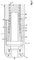
Fig. 2 dargestellte, als Ganzes mit 12 bezeichnete, Fixiereinrichtung weist eine Innenhülse 13 auf, auf der das elektrodenseitige Ende 14 der Wendel 10 sitzt. Die Innenhülse 13 ist dabei mit einem sich in distaler Richtung erweiternden Außenkonus 15 versehen, auf den bei der Montage das Wendelende 14 aufgeschoben wird und damit ebenfalls konisch aufgeweitet sitzt. - Auf die Baugruppe aus Innenhülse 13 und elektrodenseitigem Ende 14 der Wendel 10 ist ein Quetschring 16 aufgeschoben, der mit einem sich ebenfalls in distaler Richtung aufweitenden Innenkonus 17 versehen ist. Der Quetschring 16 wird vor dem Aufschieben des elektrodenseitigen Endes 14 der Wendel 10 auf diese aufgefädelt und nach dem Verbinden der Wendel 10 mit der Innenhülse 13 in distaler Richtung nachgeschoben und auf das aufgeweitete Wendelende quasi aufgequetscht. Dabei wird die das Wendelende 14 bildende Zuleitung 8 etwas deformiert, sodass eine Art Formschluss zwischen Innenhülse 13, Wendelende 14 und Quetschring 16 unter Erzielung einer mechanisch stabilen und elektrisch sicheren Verbindung zwischen diesen aus elektrisch leitfähigem Werkstoff bestehenden Bauteilen hergestellt wird. Im distalen Endbereich wird der Quetschring 16 auf einer Lagerschulter 18 am distal weisenden Ende der Innenhülse 13 durch Aufsetzen fixiert.
- Die Konuswinkel K15 bzw. K17 am Außenkonus 15 der Innenhülse 13 bzw. am Innenkonus 17 des Quetschrings 16 sind flach und liegen insbesondere unter einem Betrag von 15°, vorzugsweise beispielsweise bei 10°. Ferner stimmen sie in ihrem Winkelbetrag überein.
- Zur Herstellung einer elektrischen Verbindung zwischen der Wendel 10 und der Ringelektrode 4 ist der Quetschring 16 an seiner radial nach außen weisenden Seite 19 mit der Ringelektrode 4 elektrisch leitend, beispielsweise eine stoffschlüssige Verbindung, verbunden.
- Durch die Innenbohrung 20 der Innenhülse 13 ist unter Zwischenlage eines isolierenden Schlauchs 21 die innere Wendel 11 der Zuleitung 9 in distale Richtung zur Kopfelektrode 5 (
Fig. 3 ) weitergeführt. - In
Fig. 3 ist eine Fixiereinrichtung 12 analog der anhand vonFig. 2 erläuterten Fixiereinrichtung zur Anbindung der inneren Wendel 11 mit der Zuleitung 9 an die Kopfelektrode 5 gezeigt. Der Aufbau stimmt mit der Fixiereinrichtung 12 gemäßFig. 2 überein, insoweit ist die Beschreibung der Fixiereinrichtung 12 vonFig. 2 in vollem Umfang auf die inFig. 3 gezeigte Konstruktion übertragbar, zur Vermeidung von Wiederholungen kann darauf verwiesen werden. Konstruktiv übereinstimmende Bauteile sind mit identischen Bezugszeichen versehen. - Die Innenbohrung 20 der Innenhülse 13 bei der Fixiereinrichtung 12 an der Kopfelektrode 5 dient zum Durchführen eines Mandrins bzw. von Führungsdrähten für den Elektrodenkatheter. Mit der Innenbohrung 20 fluchtet dabei eine zentrale Kopfbohrung 22 in der Kopfelektrode 5.
- In den
Fig. 4 bis 6 ist eine alternative Ausführungsform einer Fixiereinrichtung 12' für die Verbindung einer Wendel 11 der Zuleitung 9 mit der Kopfelektrode 5 gezeigt. Diese weist eine Innenhülse 13' auf, die nicht als Konus, sondern hinsichtlich ihres Grundkörpers als Zylinderhülse ausgeführt ist. Bei etwa einem Viertel ihrer Gesamtlänge ist auf der Mantelfläche 23 der Innenhülse 13' ein Gewindeelement in Form eines über einen Teilumfang der Innenhülse 13' verlaufenden Stegs 24 ausgebildet. Wie insbesondere ausFig. 5 und 6 deutlich wird, verläuft dieser Steg 24 über einen Winkel W von 270° in Peripherrichtung P um diese Innenhülse 13'. Der Steg weist eine Höhe h auf, die etwas größer als der Durchmesser d der die Wendel bildenden Zuleitung 9 ist. Seine Breite b entspricht etwa diesem Durchmesser d. - Wie aus
Fig. 4 deutlich wird, ist die Wendel 11' mit Windungslücken versehen und kann somit auf die Innenhülse 13' über den Gewindeelement-Steg 24 aufgeschraubt werden, bis mehrere Windungen den Steg 24 passiert haben. Dann wird auf das distale Ende der Innenhülse 13' ein Quetschring 16' gegen diese aufgeschraubten Wickelwindungen 25 aufgeschoben, sodass diese Wickelwindungen 25 so beaufschlagt werden, dass sie auf Block gestaucht sind. Dieser Zustand ist inFig. 4 dargestellt. Aufgrund dieser Stauchung ist das Windungspaket 25 zwischen Quetschring 16' und Steg 24 so durch Selbsthemmung fixiert, dass ein Herausschrauben der Wendel 11' und damit eine Lösung der Verbindung zwischen dieser und der Innenhülse 13' unmöglich ist. - Der Quetschring 16' wird durch geeignete Maßnahmen, wie beispielsweise eine stoffschlüssige Verbindung, auf der Innenhülse 13' fixiert. Gleichermaßen ist wiederum die radial nach außen weisende Seite 19' des Quetschrings 16' mit der Kopfelektrode 5 durch eine stoffschlüssige Verbindung elektrisch und mechanisch sicher verbunden.
- Die Innenbohrung 20' der Innenhülse 13' dient zusammen mit der Kopfbohrung 22 der Kopfelektrode 5 wiederum zum Durchführen eines Mandrins oder von Führungsdrähten für den Elektrodenkatheter.
Claims (13)
- Elektrodenanbindung, insbesondere für einen Elektrodenkatheter, umfassend- eine Elektrode (4, 5),- eine als Wendel (10, 11, 11') ausgebildete, mit der Elektrode (4, 5) verbundene Leitung (8, 9) für elektrische Signale, und- eine Fixiereinrichtung (12, 12') für das elektrodenseitige Ende (14) der Wendel (10, 11, 11') an der Elektrode,dadurch gekennzeichnet, dass- die Fixiereinrichtung (12, 12') aufweist= eine Innenhülse (13, 13'), auf der das elektrodenseitige Ende (14) der Wendel (10, 11, 11') sitzt, und= einen Quetschring (16, 16'), der das elektrodenseitige Ende (14) der Wendel (10, 11, 11') unter Herstellung eines elektrischen Kontaktes mit der Elektrode (4, 5) und mechanischer Klemmung auf der Innenhülse (13, 13') beaufschlagt.
- Elektrodenanbindung nach Anspruch 1, dadurch gekennzeichnet, dass die Innenhülse (13) einen sich von ihrem in die Wendel (10, 11) eingreifenden Ende ausgehend erweiternden Außenkonus (15) aufweist, auf dem das Wendelende (14) ebenfalls konisch aufgeweitet sitzt, wobei der Quetschring (16) mit einem axial auf das aufgeweitete Wendelende (14) geschobenen Innenkonus (17) das Wendelende (14) festlegt.
- Elektrodenanbindung nach Anspruch 2, dadurch gekennzeichnet, dass der Quetschring (16) unter Deformation der das Wendelende (14) bildenden Leitung (8) aufgeschoben ist.
- Elektrodenanbindung nach Anspruch 2 oder 3, dadurch gekennzeichnet, dass der Quetschring (16) in seiner Fixierstellung auf einer Lagerschulter (18) an der Innenhülse (13) befestigt ist.
- Elektrodenanbindung nach einem der Ansprüche 2 bis 4, dadurch gekennzeichnet, dass die Konuswinkel (K15 bzw. K17) am Außenkonus (15) der Innenhülse (13) und am Innenkonus (17) des Quetschrings (16) kleiner als 15° sind.
- Elektrodenanbindung nach Anspruch 5, dadurch gekennzeichnet, dass die Konuswinkel (K15, K17) am Außenkonus (15) der Innenhülse (13) und am Innenkonus (17) des Quetschrings (16) übereinstimmen.
- Elektrodenanbindung nach Anspruch 1, dadurch gekennzeichnet, dass das elektrodenseitige Ende (14) der offen gewickelten Wendel (11') auf die Innenhülse (13') durch Hintergreifen eines Gewindeelementes (24) an der Innenhülse (13') aufgeschraubt und die über das Gewindeelement (24) geschraubte Partie des Wendelendes (14) durch den Quetschring (16') beaufschlagt ist.
- Elektrodenanbindung nach Anspruch 7, dadurch gekennzeichnet, dass die über das Gewindeelement (24) geschraubte Partie des Wendelendes (14) unter Stauchung axial gegen das Gewindeelement (24) beaufschlagt ist.
- Elektrodenanbindung nach Anspruch 7 oder 8, dadurch gekennzeichnet, dass die über das Gewindeelement (24) geschraubte Partie des Wendelendes (14) auf Block gestaucht ist.
- Elektrodenanbindung nach einem der Ansprüche 7 bis 9, dadurch gekennzeichnet, dass das Gewindeelement durch einen in Peripherrichtung (P) über einen Teilumfang der Innenhülse (13') verlaufenden Steg (24) gebildet ist.
- Elektrodenanbindung nach Anspruch 10, dadurch gekennzeichnet, dass der Steg (24) über einen Winkel (W) von 240° bis 300°, vorzugsweise von 270°, in Peripherrichtung (P) verläuft.
- Elektrodenanbindung nach Anspruch 10 oder 11, dadurch gekennzeichnet, dass der Steg (24) eine Höhe (h) aufweist, die größer als der Durchmesser (d) der die Wendel (11') bildenden Leitung (9) ist.
- Elektrodenanbindung nach einem der vorgenannten Ansprüche, dadurch gekennzeichnet, dass der Quetschring (16, 16') an seiner radial nach außen weisenden Seite (19, 19') mit der Elektrode (4, 5) mechanisch und elektrisch leitend verbunden ist.
Applications Claiming Priority (1)
| Application Number | Priority Date | Filing Date | Title |
|---|---|---|---|
| US36788910P | 2010-07-27 | 2010-07-27 |
Publications (2)
| Publication Number | Publication Date |
|---|---|
| EP2412400A1 true EP2412400A1 (de) | 2012-02-01 |
| EP2412400B1 EP2412400B1 (de) | 2013-08-21 |
Family
ID=44653019
Family Applications (1)
| Application Number | Title | Priority Date | Filing Date |
|---|---|---|---|
| EP20110172361 Not-in-force EP2412400B1 (de) | 2010-07-27 | 2011-07-01 | Elektrodenanbindung, insbesondere für einen Elektrodenkatheter |
Country Status (2)
| Country | Link |
|---|---|
| US (1) | US8798772B2 (de) |
| EP (1) | EP2412400B1 (de) |
Families Citing this family (2)
| Publication number | Priority date | Publication date | Assignee | Title |
|---|---|---|---|---|
| US8945025B2 (en) * | 2011-12-30 | 2015-02-03 | St. Jude Medical, Atrial Fibrillation Division, Inc. | Catheter with atraumatic tip |
| US9907948B2 (en) * | 2013-06-07 | 2018-03-06 | Cardiac Pacemakers, Inc. | Electrical and mechanical connection for coiled stimulation/sensing lead conductors |
Citations (5)
| Publication number | Priority date | Publication date | Assignee | Title |
|---|---|---|---|---|
| US4566467A (en) * | 1984-06-20 | 1986-01-28 | Cordis Corporation | Electrical connection between coiled lead conductor and lead tip electrode |
| US5569883A (en) * | 1994-08-31 | 1996-10-29 | Pacesetter, Inc. | Joint for providing a secure connection between a wound element and a mating part in a body implantable lead assembly and method for making such joint |
| US6505081B1 (en) * | 1998-03-06 | 2003-01-07 | Intermedics, Inc. | Cardiac pacemaker lead with swaged distal electrode |
| US20050228469A1 (en) * | 2004-04-12 | 2005-10-13 | Cardiac Pacemakers, Inc. | Electrode and conductor interconnect and method therefor |
| DE202005020835U1 (de) * | 2005-08-18 | 2006-10-12 | Biotronik Crm Patent Ag | Medizinische Elektrodenvorrichtung, insbesondere implantierbare kardiologische Elektrodenvorrichtung |
Family Cites Families (1)
| Publication number | Priority date | Publication date | Assignee | Title |
|---|---|---|---|---|
| DE102005039040A1 (de) * | 2005-08-18 | 2007-02-22 | Biotronik Crm Patent Ag | Implantierbare Elektrodenvorrichtung |
-
2011
- 2011-07-01 EP EP20110172361 patent/EP2412400B1/de not_active Not-in-force
- 2011-07-12 US US13/180,725 patent/US8798772B2/en not_active Expired - Fee Related
Patent Citations (5)
| Publication number | Priority date | Publication date | Assignee | Title |
|---|---|---|---|---|
| US4566467A (en) * | 1984-06-20 | 1986-01-28 | Cordis Corporation | Electrical connection between coiled lead conductor and lead tip electrode |
| US5569883A (en) * | 1994-08-31 | 1996-10-29 | Pacesetter, Inc. | Joint for providing a secure connection between a wound element and a mating part in a body implantable lead assembly and method for making such joint |
| US6505081B1 (en) * | 1998-03-06 | 2003-01-07 | Intermedics, Inc. | Cardiac pacemaker lead with swaged distal electrode |
| US20050228469A1 (en) * | 2004-04-12 | 2005-10-13 | Cardiac Pacemakers, Inc. | Electrode and conductor interconnect and method therefor |
| DE202005020835U1 (de) * | 2005-08-18 | 2006-10-12 | Biotronik Crm Patent Ag | Medizinische Elektrodenvorrichtung, insbesondere implantierbare kardiologische Elektrodenvorrichtung |
Also Published As
| Publication number | Publication date |
|---|---|
| US8798772B2 (en) | 2014-08-05 |
| EP2412400B1 (de) | 2013-08-21 |
| US20120028512A1 (en) | 2012-02-02 |
Similar Documents
| Publication | Publication Date | Title |
|---|---|---|
| EP1127552B1 (de) | Ablationskatheter zur Erzeugung linearer Läsionen in Herzmuskelgewebe | |
| EP0491979A1 (de) | Herzschrittmacher-Katheter mit zwei Polen | |
| EP2859249A1 (de) | Verbindung von federenden | |
| DE102019127691A1 (de) | Elektrisches Heizelement, elektrische Heizvorrichtung und Verfahren zur Herstellung einer elektrischen Heizvorrichtung mit einem solchen Heizelement | |
| DE102021213562A1 (de) | Elektrische Kontaktanordnung sowie vorgefertigte Baugruppe | |
| EP2662934B1 (de) | Verbindung eines elektrischen Kabels mit einem Kontaktteil | |
| DE102004055847B4 (de) | Verfahren zur Fertigung einer Batteriesensorvorrichtung | |
| EP4304900B1 (de) | Elektrische verbindung | |
| EP2412400B1 (de) | Elektrodenanbindung, insbesondere für einen Elektrodenkatheter | |
| DE102009033767B4 (de) | Anschlusselement für Leitungswendel | |
| DE102009033769B4 (de) | Crimp-Verbindung zwischen Stimulationselektrode und Leitungswendel | |
| DE102009033770B4 (de) | Verbindung zwischen Stimulationselektrode und Leitungswendel | |
| DE3304506C2 (de) | Steckvorrichtung für eine Herzschrittmacher-Elektrodenzuleitung | |
| DE68909154T2 (de) | Zündkerzenkörper mit einer Massenelektrode mit Kupferseele. | |
| DE102006037122B3 (de) | Medizinische Elektrode mit wenigstens zwei Polen und einem Stecker und deren Verwendung | |
| EP1444464A1 (de) | Elektrisch beheizbare glühkerze und verfahren zur herstellung einer elektrisch beheizbaren glühkerze | |
| EP2422839B1 (de) | Elektrodenkatheter, insbesondere zur Kardialtherapie | |
| DE60125496T2 (de) | Keramische Glühkerze und Verfahren zur Herstellung derselben | |
| DE102009014282B4 (de) | Vorrichtung, aufweisend mindestens zwei miteinander verbundene Teile aus Metall | |
| DE102020123651B4 (de) | Mehrlagige Ringelektrode mit Klemme | |
| WO2025031571A1 (de) | Verbindungselement, kontaktanordnung und verfahren zum herstellen einer kontaktanordnung | |
| DE102012213567A1 (de) | Verfahren zum verbinden eines anschlusselements mit einer metallisierung und verfahren zur herstellung eines halbleitermoduls | |
| DE102020118373B4 (de) | Mehrlagige Ringelektrode mit mehreren Öffnungen und niedrigschmelzenden Innenstrukturen | |
| CH706277A1 (de) | Verbindung von Federenden. | |
| EP4208920B1 (de) | Elektrische verbindung für kraftfahrzeugleitung |
Legal Events
| Date | Code | Title | Description |
|---|---|---|---|
| AK | Designated contracting states |
Kind code of ref document: A1 Designated state(s): AL AT BE BG CH CY CZ DE DK EE ES FI FR GB GR HR HU IE IS IT LI LT LU LV MC MK MT NL NO PL PT RO RS SE SI SK SM TR |
|
| AX | Request for extension of the european patent |
Extension state: BA ME |
|
| PUAI | Public reference made under article 153(3) epc to a published international application that has entered the european phase |
Free format text: ORIGINAL CODE: 0009012 |
|
| 17P | Request for examination filed |
Effective date: 20120730 |
|
| 17Q | First examination report despatched |
Effective date: 20120829 |
|
| GRAP | Despatch of communication of intention to grant a patent |
Free format text: ORIGINAL CODE: EPIDOSNIGR1 |
|
| RIC1 | Information provided on ipc code assigned before grant |
Ipc: H01R 4/50 20060101ALI20130308BHEP Ipc: A61N 1/05 20060101AFI20130308BHEP Ipc: A61N 1/02 20060101ALN20130308BHEP |
|
| INTG | Intention to grant announced |
Effective date: 20130327 |
|
| GRAS | Grant fee paid |
Free format text: ORIGINAL CODE: EPIDOSNIGR3 |
|
| GRAP | Despatch of communication of intention to grant a patent |
Free format text: ORIGINAL CODE: EPIDOSNIGR1 |
|
| GRAA | (expected) grant |
Free format text: ORIGINAL CODE: 0009210 |
|
| INTG | Intention to grant announced |
Effective date: 20130628 |
|
| RIC1 | Information provided on ipc code assigned before grant |
Ipc: H01R 4/50 20060101ALI20130614BHEP Ipc: A61N 1/05 20060101AFI20130614BHEP Ipc: A61N 1/02 20060101ALN20130614BHEP |
|
| AK | Designated contracting states |
Kind code of ref document: B1 Designated state(s): AL AT BE BG CH CY CZ DE DK EE ES FI FR GB GR HR HU IE IS IT LI LT LU LV MC MK MT NL NO PL PT RO RS SE SI SK SM TR |
|
| REG | Reference to a national code |
Ref country code: GB Ref legal event code: FG4D Free format text: NOT ENGLISH |
|
| REG | Reference to a national code |
Ref country code: CH Ref legal event code: EP |
|
| REG | Reference to a national code |
Ref country code: AT Ref legal event code: REF Ref document number: 627709 Country of ref document: AT Kind code of ref document: T Effective date: 20130915 |
|
| REG | Reference to a national code |
Ref country code: IE Ref legal event code: FG4D Free format text: LANGUAGE OF EP DOCUMENT: GERMAN |
|
| REG | Reference to a national code |
Ref country code: DE Ref legal event code: R096 Ref document number: 502011001199 Country of ref document: DE Effective date: 20131017 |
|
| REG | Reference to a national code |
Ref country code: NL Ref legal event code: VDEP Effective date: 20130821 |
|
| REG | Reference to a national code |
Ref country code: LT Ref legal event code: MG4D |
|
| PG25 | Lapsed in a contracting state [announced via postgrant information from national office to epo] |
Ref country code: CY Free format text: LAPSE BECAUSE OF FAILURE TO SUBMIT A TRANSLATION OF THE DESCRIPTION OR TO PAY THE FEE WITHIN THE PRESCRIBED TIME-LIMIT Effective date: 20130807 Ref country code: SE Free format text: LAPSE BECAUSE OF FAILURE TO SUBMIT A TRANSLATION OF THE DESCRIPTION OR TO PAY THE FEE WITHIN THE PRESCRIBED TIME-LIMIT Effective date: 20130821 Ref country code: NO Free format text: LAPSE BECAUSE OF FAILURE TO SUBMIT A TRANSLATION OF THE DESCRIPTION OR TO PAY THE FEE WITHIN THE PRESCRIBED TIME-LIMIT Effective date: 20131121 Ref country code: HR Free format text: LAPSE BECAUSE OF FAILURE TO SUBMIT A TRANSLATION OF THE DESCRIPTION OR TO PAY THE FEE WITHIN THE PRESCRIBED TIME-LIMIT Effective date: 20130821 Ref country code: PT Free format text: LAPSE BECAUSE OF FAILURE TO SUBMIT A TRANSLATION OF THE DESCRIPTION OR TO PAY THE FEE WITHIN THE PRESCRIBED TIME-LIMIT Effective date: 20131223 Ref country code: IS Free format text: LAPSE BECAUSE OF FAILURE TO SUBMIT A TRANSLATION OF THE DESCRIPTION OR TO PAY THE FEE WITHIN THE PRESCRIBED TIME-LIMIT Effective date: 20131221 Ref country code: LT Free format text: LAPSE BECAUSE OF FAILURE TO SUBMIT A TRANSLATION OF THE DESCRIPTION OR TO PAY THE FEE WITHIN THE PRESCRIBED TIME-LIMIT Effective date: 20130821 |
|
| PG25 | Lapsed in a contracting state [announced via postgrant information from national office to epo] |
Ref country code: LV Free format text: LAPSE BECAUSE OF FAILURE TO SUBMIT A TRANSLATION OF THE DESCRIPTION OR TO PAY THE FEE WITHIN THE PRESCRIBED TIME-LIMIT Effective date: 20130821 Ref country code: PL Free format text: LAPSE BECAUSE OF FAILURE TO SUBMIT A TRANSLATION OF THE DESCRIPTION OR TO PAY THE FEE WITHIN THE PRESCRIBED TIME-LIMIT Effective date: 20130821 Ref country code: GR Free format text: LAPSE BECAUSE OF FAILURE TO SUBMIT A TRANSLATION OF THE DESCRIPTION OR TO PAY THE FEE WITHIN THE PRESCRIBED TIME-LIMIT Effective date: 20131122 Ref country code: SI Free format text: LAPSE BECAUSE OF FAILURE TO SUBMIT A TRANSLATION OF THE DESCRIPTION OR TO PAY THE FEE WITHIN THE PRESCRIBED TIME-LIMIT Effective date: 20130821 Ref country code: FI Free format text: LAPSE BECAUSE OF FAILURE TO SUBMIT A TRANSLATION OF THE DESCRIPTION OR TO PAY THE FEE WITHIN THE PRESCRIBED TIME-LIMIT Effective date: 20130821 |
|
| PG25 | Lapsed in a contracting state [announced via postgrant information from national office to epo] |
Ref country code: CY Free format text: LAPSE BECAUSE OF FAILURE TO SUBMIT A TRANSLATION OF THE DESCRIPTION OR TO PAY THE FEE WITHIN THE PRESCRIBED TIME-LIMIT Effective date: 20130821 |
|
| PG25 | Lapsed in a contracting state [announced via postgrant information from national office to epo] |
Ref country code: DK Free format text: LAPSE BECAUSE OF FAILURE TO SUBMIT A TRANSLATION OF THE DESCRIPTION OR TO PAY THE FEE WITHIN THE PRESCRIBED TIME-LIMIT Effective date: 20130821 Ref country code: RO Free format text: LAPSE BECAUSE OF FAILURE TO SUBMIT A TRANSLATION OF THE DESCRIPTION OR TO PAY THE FEE WITHIN THE PRESCRIBED TIME-LIMIT Effective date: 20130821 Ref country code: CZ Free format text: LAPSE BECAUSE OF FAILURE TO SUBMIT A TRANSLATION OF THE DESCRIPTION OR TO PAY THE FEE WITHIN THE PRESCRIBED TIME-LIMIT Effective date: 20130821 Ref country code: EE Free format text: LAPSE BECAUSE OF FAILURE TO SUBMIT A TRANSLATION OF THE DESCRIPTION OR TO PAY THE FEE WITHIN THE PRESCRIBED TIME-LIMIT Effective date: 20130821 Ref country code: NL Free format text: LAPSE BECAUSE OF FAILURE TO SUBMIT A TRANSLATION OF THE DESCRIPTION OR TO PAY THE FEE WITHIN THE PRESCRIBED TIME-LIMIT Effective date: 20130821 Ref country code: SK Free format text: LAPSE BECAUSE OF FAILURE TO SUBMIT A TRANSLATION OF THE DESCRIPTION OR TO PAY THE FEE WITHIN THE PRESCRIBED TIME-LIMIT Effective date: 20130821 |
|
| PG25 | Lapsed in a contracting state [announced via postgrant information from national office to epo] |
Ref country code: IT Free format text: LAPSE BECAUSE OF FAILURE TO SUBMIT A TRANSLATION OF THE DESCRIPTION OR TO PAY THE FEE WITHIN THE PRESCRIBED TIME-LIMIT Effective date: 20130821 Ref country code: ES Free format text: LAPSE BECAUSE OF FAILURE TO SUBMIT A TRANSLATION OF THE DESCRIPTION OR TO PAY THE FEE WITHIN THE PRESCRIBED TIME-LIMIT Effective date: 20130821 |
|
| PLBE | No opposition filed within time limit |
Free format text: ORIGINAL CODE: 0009261 |
|
| STAA | Information on the status of an ep patent application or granted ep patent |
Free format text: STATUS: NO OPPOSITION FILED WITHIN TIME LIMIT |
|
| 26N | No opposition filed |
Effective date: 20140522 |
|
| REG | Reference to a national code |
Ref country code: DE Ref legal event code: R097 Ref document number: 502011001199 Country of ref document: DE Effective date: 20140522 |
|
| PG25 | Lapsed in a contracting state [announced via postgrant information from national office to epo] |
Ref country code: LU Free format text: LAPSE BECAUSE OF FAILURE TO SUBMIT A TRANSLATION OF THE DESCRIPTION OR TO PAY THE FEE WITHIN THE PRESCRIBED TIME-LIMIT Effective date: 20140701 |
|
| REG | Reference to a national code |
Ref country code: FR Ref legal event code: ST Effective date: 20150331 |
|
| PG25 | Lapsed in a contracting state [announced via postgrant information from national office to epo] |
Ref country code: FR Free format text: LAPSE BECAUSE OF NON-PAYMENT OF DUE FEES Effective date: 20140731 |
|
| REG | Reference to a national code |
Ref country code: DE Ref legal event code: R082 Ref document number: 502011001199 Country of ref document: DE Representative=s name: RANDOLL, SOEREN, DIPL.-CHEM. UNIV. DR. RER. NA, DE |
|
| GBPC | Gb: european patent ceased through non-payment of renewal fee |
Effective date: 20150701 |
|
| PG25 | Lapsed in a contracting state [announced via postgrant information from national office to epo] |
Ref country code: GB Free format text: LAPSE BECAUSE OF NON-PAYMENT OF DUE FEES Effective date: 20150701 Ref country code: SM Free format text: LAPSE BECAUSE OF FAILURE TO SUBMIT A TRANSLATION OF THE DESCRIPTION OR TO PAY THE FEE WITHIN THE PRESCRIBED TIME-LIMIT Effective date: 20130821 Ref country code: MC Free format text: LAPSE BECAUSE OF FAILURE TO SUBMIT A TRANSLATION OF THE DESCRIPTION OR TO PAY THE FEE WITHIN THE PRESCRIBED TIME-LIMIT Effective date: 20130821 |
|
| PG25 | Lapsed in a contracting state [announced via postgrant information from national office to epo] |
Ref country code: BG Free format text: LAPSE BECAUSE OF FAILURE TO SUBMIT A TRANSLATION OF THE DESCRIPTION OR TO PAY THE FEE WITHIN THE PRESCRIBED TIME-LIMIT Effective date: 20130821 Ref country code: RS Free format text: LAPSE BECAUSE OF FAILURE TO SUBMIT A TRANSLATION OF THE DESCRIPTION OR TO PAY THE FEE WITHIN THE PRESCRIBED TIME-LIMIT Effective date: 20130821 Ref country code: MT Free format text: LAPSE BECAUSE OF FAILURE TO SUBMIT A TRANSLATION OF THE DESCRIPTION OR TO PAY THE FEE WITHIN THE PRESCRIBED TIME-LIMIT Effective date: 20130821 |
|
| PG25 | Lapsed in a contracting state [announced via postgrant information from national office to epo] |
Ref country code: BE Free format text: LAPSE BECAUSE OF FAILURE TO SUBMIT A TRANSLATION OF THE DESCRIPTION OR TO PAY THE FEE WITHIN THE PRESCRIBED TIME-LIMIT Effective date: 20140731 Ref country code: TR Free format text: LAPSE BECAUSE OF FAILURE TO SUBMIT A TRANSLATION OF THE DESCRIPTION OR TO PAY THE FEE WITHIN THE PRESCRIBED TIME-LIMIT Effective date: 20130821 Ref country code: HU Free format text: LAPSE BECAUSE OF FAILURE TO SUBMIT A TRANSLATION OF THE DESCRIPTION OR TO PAY THE FEE WITHIN THE PRESCRIBED TIME-LIMIT; INVALID AB INITIO Effective date: 20110701 |
|
| REG | Reference to a national code |
Ref country code: AT Ref legal event code: MM01 Ref document number: 627709 Country of ref document: AT Kind code of ref document: T Effective date: 20160701 |
|
| PG25 | Lapsed in a contracting state [announced via postgrant information from national office to epo] |
Ref country code: AT Free format text: LAPSE BECAUSE OF NON-PAYMENT OF DUE FEES Effective date: 20160701 |
|
| PG25 | Lapsed in a contracting state [announced via postgrant information from national office to epo] |
Ref country code: MK Free format text: LAPSE BECAUSE OF FAILURE TO SUBMIT A TRANSLATION OF THE DESCRIPTION OR TO PAY THE FEE WITHIN THE PRESCRIBED TIME-LIMIT Effective date: 20130821 |
|
| PG25 | Lapsed in a contracting state [announced via postgrant information from national office to epo] |
Ref country code: AL Free format text: LAPSE BECAUSE OF FAILURE TO SUBMIT A TRANSLATION OF THE DESCRIPTION OR TO PAY THE FEE WITHIN THE PRESCRIBED TIME-LIMIT Effective date: 20130821 |
|
| PGFP | Annual fee paid to national office [announced via postgrant information from national office to epo] |
Ref country code: IE Payment date: 20210726 Year of fee payment: 11 |
|
| PGFP | Annual fee paid to national office [announced via postgrant information from national office to epo] |
Ref country code: CH Payment date: 20210723 Year of fee payment: 11 Ref country code: DE Payment date: 20210726 Year of fee payment: 11 |
|
| REG | Reference to a national code |
Ref country code: DE Ref legal event code: R119 Ref document number: 502011001199 Country of ref document: DE |
|
| REG | Reference to a national code |
Ref country code: CH Ref legal event code: PL |
|
| PG25 | Lapsed in a contracting state [announced via postgrant information from national office to epo] |
Ref country code: LI Free format text: LAPSE BECAUSE OF NON-PAYMENT OF DUE FEES Effective date: 20220731 Ref country code: CH Free format text: LAPSE BECAUSE OF NON-PAYMENT OF DUE FEES Effective date: 20220731 |
|
| PG25 | Lapsed in a contracting state [announced via postgrant information from national office to epo] |
Ref country code: DE Free format text: LAPSE BECAUSE OF NON-PAYMENT OF DUE FEES Effective date: 20230201 |
|
| PG25 | Lapsed in a contracting state [announced via postgrant information from national office to epo] |
Ref country code: IE Free format text: LAPSE BECAUSE OF NON-PAYMENT OF DUE FEES Effective date: 20220701 |