EP2412044B1 - Batteriezellenverbinder - Google Patents
Batteriezellenverbinder Download PDFInfo
- Publication number
- EP2412044B1 EP2412044B1 EP10709810.5A EP10709810A EP2412044B1 EP 2412044 B1 EP2412044 B1 EP 2412044B1 EP 10709810 A EP10709810 A EP 10709810A EP 2412044 B1 EP2412044 B1 EP 2412044B1
- Authority
- EP
- European Patent Office
- Prior art keywords
- limb
- battery cell
- cell connector
- shoulder
- leg
- Prior art date
- Legal status (The legal status is an assumption and is not a legal conclusion. Google has not performed a legal analysis and makes no representation as to the accuracy of the status listed.)
- Active
Links
Images
Classifications
-
- H—ELECTRICITY
- H01—ELECTRIC ELEMENTS
- H01M—PROCESSES OR MEANS, e.g. BATTERIES, FOR THE DIRECT CONVERSION OF CHEMICAL ENERGY INTO ELECTRICAL ENERGY
- H01M50/00—Constructional details or processes of manufacture of the non-active parts of electrochemical cells other than fuel cells, e.g. hybrid cells
- H01M50/50—Current conducting connections for cells or batteries
- H01M50/531—Electrode connections inside a battery casing
-
- H—ELECTRICITY
- H01—ELECTRIC ELEMENTS
- H01M—PROCESSES OR MEANS, e.g. BATTERIES, FOR THE DIRECT CONVERSION OF CHEMICAL ENERGY INTO ELECTRICAL ENERGY
- H01M2220/00—Batteries for particular applications
- H01M2220/20—Batteries in motive systems, e.g. vehicle, ship, plane
-
- H—ELECTRICITY
- H01—ELECTRIC ELEMENTS
- H01M—PROCESSES OR MEANS, e.g. BATTERIES, FOR THE DIRECT CONVERSION OF CHEMICAL ENERGY INTO ELECTRICAL ENERGY
- H01M50/00—Constructional details or processes of manufacture of the non-active parts of electrochemical cells other than fuel cells, e.g. hybrid cells
- H01M50/50—Current conducting connections for cells or batteries
- H01M50/502—Interconnectors for connecting terminals of adjacent batteries; Interconnectors for connecting cells outside a battery casing
- H01M50/514—Methods for interconnecting adjacent batteries or cells
- H01M50/516—Methods for interconnecting adjacent batteries or cells by welding, soldering or brazing
-
- H—ELECTRICITY
- H01—ELECTRIC ELEMENTS
- H01M—PROCESSES OR MEANS, e.g. BATTERIES, FOR THE DIRECT CONVERSION OF CHEMICAL ENERGY INTO ELECTRICAL ENERGY
- H01M50/00—Constructional details or processes of manufacture of the non-active parts of electrochemical cells other than fuel cells, e.g. hybrid cells
- H01M50/50—Current conducting connections for cells or batteries
- H01M50/531—Electrode connections inside a battery casing
- H01M50/54—Connection of several leads or tabs of plate-like electrode stacks, e.g. electrode pole straps or bridges
-
- H—ELECTRICITY
- H01—ELECTRIC ELEMENTS
- H01M—PROCESSES OR MEANS, e.g. BATTERIES, FOR THE DIRECT CONVERSION OF CHEMICAL ENERGY INTO ELECTRICAL ENERGY
- H01M50/00—Constructional details or processes of manufacture of the non-active parts of electrochemical cells other than fuel cells, e.g. hybrid cells
- H01M50/50—Current conducting connections for cells or batteries
- H01M50/531—Electrode connections inside a battery casing
- H01M50/54—Connection of several leads or tabs of plate-like electrode stacks, e.g. electrode pole straps or bridges
- H01M50/541—Connection of several leads or tabs of plate-like electrode stacks, e.g. electrode pole straps or bridges for lead-acid accumulators
-
- Y—GENERAL TAGGING OF NEW TECHNOLOGICAL DEVELOPMENTS; GENERAL TAGGING OF CROSS-SECTIONAL TECHNOLOGIES SPANNING OVER SEVERAL SECTIONS OF THE IPC; TECHNICAL SUBJECTS COVERED BY FORMER USPC CROSS-REFERENCE ART COLLECTIONS [XRACs] AND DIGESTS
- Y02—TECHNOLOGIES OR APPLICATIONS FOR MITIGATION OR ADAPTATION AGAINST CLIMATE CHANGE
- Y02E—REDUCTION OF GREENHOUSE GAS [GHG] EMISSIONS, RELATED TO ENERGY GENERATION, TRANSMISSION OR DISTRIBUTION
- Y02E60/00—Enabling technologies; Technologies with a potential or indirect contribution to GHG emissions mitigation
- Y02E60/10—Energy storage using batteries
Definitions
- the invention relates to a battery cell connector according to the preamble of claim 1.
- battery cell connectors are used for example in electrochemical batteries, for.
- starter batteries for automobiles used for internal connection between the electrode stacks of the cells of the battery.
- Generic battery cell connectors are for example from the DE 10 2007 022 246 A1 , of the JP 57111950 or the US 5,424,148 known.
- the invention has for its object to provide a battery cell connector with improved compared to the known battery cell connectors high-current strength.
- high-current strength means that the battery cell connector is suitable for permanently transmitting the highest possible current or for transmitting the highest possible current for as long as possible without damage.
- the battery cell connector according to the invention has the advantage of achieving a significantly improved high-current resistance by the introduction of a specific arranged and shaped shoulder extending between the two legs of the battery cell connector.
- shoulder a wall-like connecting element is referred to in this context, which will be described in more detail below with reference to the embodiments.
- the shoulder designed according to the invention having a non-linear, convex height profile, it has been found that, on the one hand, the flow of current through the battery cell connector is favored, which already counteracts heating of the battery cell connector due to high currents.
- the shape of the shoulder according to the invention causes an improved temperature distribution in a current-induced heating of the battery cell connector, such that the temperature distribution is uniform and also an improved heat dissipation is made possible.
- the advantages explained above support each other in a synergistic manner, so that a considerable improvement in the high-current resistance of the battery cell connector can be achieved by a measure which is relatively simple to produce, such as the inventive shaping of the shoulder.
- the thickness of the shoulder increases, relative to the same contour line, from the first leg to the second leg.
- the increase in the thickness takes place in a linear or progressive manner.
- the course of the height of the shoulder is also advantageous to make the course of the height of the shoulder to the second leg towards degressive.
- the top of the shoulder in the vicinity of the second leg is nearly parallel to the side of the first leg facing away from the connection side of the battery cell connector.
- the shoulder as viewed from the side opposite the connection side, forms an at least approximately right angle to the second leg.
- Battery cell connectors are used in the battery to (in the literature sometimes referred to as pole plates) electrodes of the same polarity with each other connect and connect to a battery cell connector of an adjacent battery cell.
- the battery cell connector shown in the figures is used to connect the electrodes of a lead-acid battery with a battery cell connector of an adjacent battery cell of the lead-acid battery.
- a plurality of electrodes is connected via terminal lugs to the battery cell connector.
- the electrodes are usually connected in a Fahnenangusshabilit with the battery cell connectors. Subsequently, these connected electrodes are installed in the lead-acid battery.
- the battery cell connector connects the electrodes of a plate set, i. H. either the positive or the negative plates, with each other electrically and mechanically.
- the battery cell connector shown in FIGS. B. used in so-called AGM batteries.
- the battery cell connector is advantageously designed as a so-called side connector, which has a relatively low height. As a result, the battery cell connector in the battery builds relatively low, which improves the utilization of the available battery cell height for the electrodes.
- the battery cell connector according to the invention is predominantly not immersed in the battery acid. There is thus essentially no direct cooling by the liquid, so that the battery cell connector at a load with high currents, eg. B. currents above 500 amperes, can heat up relatively quickly. In this case, it may happen that the battery cell connector is damaged, for. B. by melting individual areas. Melting occurs in known battery cell connectors, in particular at a weld between the first and the second leg of the battery cell connector.
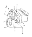
- FIGS. 1 and 2 To better illustrate the different orientations of the components of the battery cell connector explained below is in the FIGS. 1 and 2 a coordinate system with the axes L, H and D shown.
- the axis L extends in the longitudinal direction of the first leg 1 of the battery cell connector.
- the axis H extends in the vertical direction, and the axis D extends in the transverse direction, ie in the dimension of the width of the first leg first
- the first leg 1 has a connection side 3 which is provided for connection to a plurality of electrodes of the battery.
- the electrodes are in the FIG. 1 only partially shown in the form of terminal lugs 12.
- the connecting side 3 is opposite to a side 4 of the first leg.
- the second leg 2 is arranged substantially perpendicular to the first leg and extends away from the side 4.
- the second leg 2 also has an extension beyond the first leg 1 in the direction of the axis D, d. H. in the transverse direction of the first leg 1.
- the second leg 2 has a contact tab 7, which serves for the electrical connection of the electrodes to a contact tab of a battery cell connector of an adjacent battery cell.
- the contact tab 7 has a slot-like opening 8.
- a shoulder 5 is provided, which extends from the first leg 1 to the second leg 2 and forms a wall-like connection between these legs 1, 2.
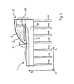
- the shoulder 5 has a particular from the FIG. 2 recognizable course of the height h, measured in the direction of the axis H, which is non-linear and convex with respect to the first and second legs 1, 2. In this way, starting from the side 4 of the first leg 1, an initially relatively steep increase in the height h and to the second leg 2 towards a flattening of the course of the height h, such that the course is almost horizontal or parallel to the page 4. Overall, this results in a degressive height profile.
- the shoulder 5 has a chamfer 6.
- the shoulder 5 also has a thickness d which varies in the direction of the axis L, the thickness d being measured in the direction of the axis D at a constant height value (in the direction h).
- the thickness d increases from the first leg 1 to the second leg 2 in such a way that a linear or progressive course results. This results in a relatively large accumulation of material in the vicinity of the second leg second
- the battery cell connector of the invention can withstand a high current load longer.
- the first leg 1 also has an increase in its thickness, measured in the direction of the axis H on. As in particular in the FIG. 2 can be seen, the material thickness of the first leg 1 to the second leg 2 in a region 9 increases.
- the second leg 2 has, in the region in which it is connected to the first leg 1, a chamfered region 10, such that the height of the second leg 2, measured in the direction of the axis H, facing that of the first leg 1 End of the second leg 2 decreases substantially linearly.
- a wall 11 is provided below the chamfered portion 10.
- the section 10, in conjunction with the wall 11, advantageously effects a mechanical stabilization of the battery cell connector and, in addition, a power line.
- the high-current resistance of the battery cell connector can be further improved.
- the described battery cell connector has already been studied under extreme conditions. It has been found that with an overload of the battery cell connector with a current of 800 amps, an improvement in the operating time could be achieved until the melting of previously about 44 seconds to 60 seconds.
- the battery cell connector according to the invention thus contributes significantly to an improvement in the function and reliability of starter batteries in vehicles.
Landscapes
- Chemical & Material Sciences (AREA)
- Chemical Kinetics & Catalysis (AREA)
- Electrochemistry (AREA)
- General Chemical & Material Sciences (AREA)
- Connection Of Batteries Or Terminals (AREA)
- Battery Mounting, Suspending (AREA)
Description
- Die Erfindung betrifft einen Batteriezellenverbinder gemäß dem Oberbegriff des Patentanspruchs 1. Derartige Batteriezellenverbinder werden beispielsweise in elektrochemischen Batterien, z. B. Starterbatterien für Automobile, zur internen Verbindung zwischen den Elektroden-Stapeln der Zellen der Batterie verwendet.
- Gattungsgemäße Batteriezellenverbinder sind beispielsweise aus der
DE 10 2007 022 246 A1 , derJP 57111950 US 5,424,148 bekannt. - Der Erfindung liegt die Aufgabe zugrunde, einen Batteriezellenverbinder mit einer im Vergleich zu den bekannten Batteriezellenverbindern verbesserten Hochstromfestigkeit anzugeben.
- Diese Aufgabe wird durch die in dem Patentanspruch 1 angegebene Erfindung gelöst. Vorteilhafte Weiterbildungen der Erfindung sind in den Unteransprüchen angegeben.
- Mit dem Begriff der Hochstromfestigkeit ist eine Eignung des Batteriezellenverbinders gemeint, einen möglichst hohen Strom dauerhaft übertragen zu können oder einen möglichst hohen Strom eine möglichst lange Zeit beschädigungsfrei übertragen zu können.
- Der erfindungsgemäße Batteriezellenverbinder hat den Vorteil, eine wesentlich verbesserte Hochstromfestigkeit durch die Einführung einer in bestimmter Weise angeordneten und geformten Schulter zu erzielen, die sich zwischen den zwei Schenkeln des Batteriezellenverbinders erstreckt. Als Schulter wird in diesem Zusammenhang ein wandartiges Verbindungselement bezeichnet, das nachfolgend anhand der Ausführungsbeispiele noch näher beschrieben wird. Durch die erfindungsgemäß gestaltete Schulter mit einem nicht-linearen, konvexen Höhenverlauf kann, wie festgestellt wurde, einerseits der Stromfluss durch den Batteriezellenverbinder begünstigt werden, was bereits einer Erwärmung des Batteriezellenverbinders auf Grund hoher Ströme entgegenwirkt. Zudem bewirkt die erfindungsgemäße Formgebung der Schulter eine verbesserte Temperaturverteilung bei einer strombedingten Erwärmung des Batteriezellenverbinders, derart, dass die Temperaturverteilung gleichmäßiger wird und zudem eine verbesserte Wärmeabfuhr ermöglicht wird. Wie festgestellt wurde, unterstützen die zuvor erläuterten Vorteile einander in synergetischer Weise, so dass durch eine produktionstechnisch relativ einfach zu realisierende Maßnahme wie der erfindungsgemäßen Formgebung der Schulter eine erhebliche Verbesserung der Hochstromfestigkeit des Batteriezellenverbinders erzielt werden kann.
- Gemäß einer vorteilhaften Weiterbildung der Erfindung nimmt die Dicke der Schulter, bezogen auf dieselbe Höhenlinie, von dem ersten Schenkel zu dem zweiten Schenkel hin zu. Gemäß einer weiteren Weiterbildung erfolgt die Zunahme der Dicke in einer linearen oder progressiven Art. Durch diese Maßnahmen kann die Hochstromfestigkeit des erfindungsgemäßen Batteriezellenverbinders zusätzlich verbessert werden. Es wurde nämlich herausgefunden, dass eine Materialhäufung im Bereich des Übergangs von dem ersten Schenkel zu dem zweiten Schenkel des Batteriezellenverbinders besondere Verbesserungen hinsichtlich der Hochstromfähigkeit erbringt. Mit einer Materialhäufung ist gemeint, dass die genannten Verbesserungen dadurch begünstigt werden, dass möglichst viel Material in der Schulter in der Nähe des Übergangs von dem ersten zu dem zweiten Schenkel vorgesehen wird.
- Es ist zudem vorteilhaft, den Verlauf der Höhe der Schulter zu dem zweiten Schenkel hin degressiv zu gestalten. Vorteilhaft verläuft die Oberseite der Schulter in der Nähe des zweiten Schenkels nahezu parallel zu der der Verbindungsseite des Batteriezellenverbinders abgewandten Seite des ersten Schenkels. Durch eine derart abflachende Höhenkontur der Schulter wird zudem der Stromfluss durch den Batteriezellenverbinder optimiert und somit ebenfalls die Hochstromfestigkeit verbessert. Vorteilhaft ist es, die Schulter derart auszubilden, dass die Zunahme der Höhe der Schulter nicht-linear erfolgt, sondern mit einem zunächst relativ steilen Anstieg und einem dann zu dem zweiten Schenkel hin nahezu waagerechten Verlauf der Höhe.
- Gemäß einer vorteilhaften Weiterbildung der Erfindung bildet die Schulter, betrachtet aus der Sicht der der Verbindungsseite gegenüberliegenden Seite, einen zumindest näherungsweise rechten Winkel zu dem zweiten Schenkel.
- Die Erfindung wird nachfolgend anhand eines Ausführungsbeispiels unter Verwendung von Zeichnungen näher erläutert.
- Es zeigen
- Figur 1
- einen erfindungsgemäßen Batteriezellenverbinder in perspektivischer Darstellung und
- Figur 2
- den Batteriezellenverbinder gemäß
Figur 1 in Seitenansicht. - In den Figuren werden gleiche Bezugszeichen für einander entsprechende Elemente verwendet.
- Batteriezellenverbinder werden in der Batterie dazu verwendet, (in der Literatur teilweise auch als Polplatten bezeichnete) Elektroden gleicher Polarität miteinander zu verbinden und eine Verbindung zu einem Batteriezellenverbinder einer benachbarten Batteriezelle herzustellen.
- Der in den Figuren dargestellte Batteriezellenverbinder dient zur Verbindung der Elektroden eines Bleiakkumulators mit einem Batteriezellenverbinder einer benachbarten Batteriezelle des Bleiakkumulators. Hierbei wird eine Mehrzahl von Elektroden über Anschlussfahnen an den Batteriezellenverbinder angeschlossen. Bei der Fertigung solcher Bleiakkumulatoren werden die Elektroden meist in einem Fahnenangussverfahren mit den Batteriezellenverbindern verbunden. Anschließend werden diese verbundenen Elektroden in dem Bleiakkumulator verbaut. Der Batteriezellenverbinder verbindet die Elektroden eines Plattensatzes, d. h. entweder der positiven oder der negativen Platten, untereinander elektrisch und mechanisch. Der in den Figuren dargestellte Batteriezellenverbinder kann z. B. in so genannten AGM-Batterien verwendet werden. Hierfür ist der Batteriezellenverbinder vorteilhaft als so genannter Seitenverbinder ausgebildet, der eine relativ geringe Bauhöhe aufweist. Hierdurch baut der Batteriezellenverbinder in der Batterie relativ niedrig, was die Ausnutzung der zur Verfügung stehenden Batteriezellenhöhe für die Elektroden verbessert.
- Nach Einbau in die Batterie ist der erfindungsgemäßen Batteriezellenverbinder überwiegend nicht in die Batteriesäure eingetaucht. Es erfolgt somit im Wesentlichen keine direkte Kühlung durch die Flüssigkeit, so dass sich der Batteriezellenverbinder bei einer Belastung mit hohen Strömen, z. B. Strömen oberhalb von 500 Ampere, relativ schnell stark erhitzen kann. Hierbei kann es vorkommen, dass der Batteriezellenverbinder beschädigt wird, z. B. durch Schmelzen einzelner Bereiche. Ein Schmelzen tritt bei bekannten Batteriezellenverbindern insbesondere an einer Schweißstelle zwischen dem ersten und dem zweiten Schenkel des Batteriezellenverbinders auf. Da bei einer solchen Anordnung von Batteriezellenverbindern eine Kühlung an den am stärksten temperaturbelasteten Stellen im Wesentlichen durch Wärmeleitung in die Elektroden und in geringem Ausmaß durch Konvektion erfolgt, kann es in Folge der relativ geringen Wärmekapazität relativ schnell zu starken Erwärmungen des Batteriezellenverbinders kommen.
- Zur besseren Darstellung der verschiedenen Ausrichtungen der Bestandteile des nachfolgend erläuterten Batteriezellenverbinders ist in den
Figuren 1 und2 ein Koordinatensystem mit den Achsen L, H und D dargestellt. Die Achse L erstreckt sich in Längsrichtung des ersten Schenkels 1 des Batteriezellenverbinders. Die Achse H erstreckt sich in Hochrichtung, und die Achse D erstreckt sich in Querrichtung, d. h. in der Dimension der Breite des ersten Schenkels 1. - Der erste Schenkel 1 weist eine Verbindungsseite 3 auf, die zur Verbindung mit einer Mehrzahl von Elektroden der Batterie vorgesehen ist. Die Elektroden sind in der
Figur 1 nur ausschnittsweise in Form von Anschlussfahnen 12 dargestellt. Der Verbindungsseite 3 liegt eine Seite 4 des ersten Schenkels gegenüber. Der zweite Schenkel 2 ist im Wesentlichen senkrecht zum ersten Schenkel angeordnet und erstreckt sich von der Seite 4 fort. - Der zweite Schenkel 2 weist zudem eine Erstreckung über den ersten Schenkel 1 hinaus in Richtung der Achse D auf, d. h. in Querrichtung des ersten Schenkels 1. In diesem Bereich weist der zweite Schenkel 2 eine Kontaktlasche 7 auf, die zur elektrischen Verbindung von den Elektroden mit einer Kontaktlasche eines Batteriezellenverbinders einer benachbarten Batteriezelle dient. Die Kontaktlasche 7 weist eine langlochartige Öffnung 8 auf. Bei der Montage der Batterie werden dann die Kontaktlaschen von Batteriezellenverbindern benachbarter Batteriezellen im Bereich der langlochartigen Öffnungen miteinander verschweißt.
- Weiterhin ist eine Schulter 5 vorgesehen, die sich von dem ersten Schenkel 1 zu dem zweiten Schenkel 2 erstreckt und eine wandartige Verbindung zwischen diesen Schenkeln 1, 2 bildet. Die Schulter 5 weist einen insbesondere aus der
Figur 2 erkennbaren Verlauf der Höhe h auf, gemessen in Richtung der Achse H, der nicht-linear ist und bezüglich des ersten und des zweiten Schenkels 1, 2 konvex ist. Hierdurch erfolgt ausgehend von der Seite 4 des ersten Schenkels 1 ein zunächst relativ steiler Anstieg der Höhe h und zu dem zweiten Schenkel 2 hin eine Abflachung des Verlaufs der Höhe h, derart, dass der Verlauf nahezu waagerecht bzw. parallel zur Seite 4 verläuft. Insgesamt ergibt sich hierdurch ein degressiver Höhenverlauf. Entlang des Höhenverlaufs weist die Schulter 5 eine Fase 6 auf. - Die Schulter 5 weist zudem eine sich in Richtung der Achse L verändernde Dicke d auf, wobei die Dicke d in Richtung der Achse D bei einem gleich bleibenden Höhenwert (in Richtung h) gemessen ist. Die Dicke d nimmt von dem ersten Schenkel 1 zu dem zweiten Schenkel 2 hin zu, derart, dass sich ein linearer oder progressiver Verlauf ergibt. Hierdurch ergibt sich eine relativ große Materialhäufung in der Nähe des zweiten Schenkels 2.
- Durch die verschiedenen Maßnahmen zur Materialanhäufung in diesem besonders stark wärmebelasteten Bereich wird zudem eine höhere Wärmespeicherkapazität bereitgestellt, was den Vorteil hat, dass eine Erwärmung langsamer als bei bekannten Batteriezellenverbindern erfolgt. Daher kann der erfindungsgemäße Batteriezellenverbinder einer hohen Strombelastung länger standhalten.
- Der erste Schenkel 1 weist ebenfalls eine Zunahme seiner Dicke, gemessen in Richtung der Achse H, auf. Wie insbesondere in der
Figur 2 erkennbar ist, nimmt die Materialdicke des ersten Schenkels 1 zu dem zweiten Schenkel 2 in einem Bereich 9 zu. - Der zweite Schenkel 2 weist in dem Bereich, in dem er mit dem ersten Schenkel 1 verbunden ist, einen abgeschrägten Bereich 10 auf, derart, dass die Höhe des zweiten Schenkels 2, gemessen in Richtung der Achse H, zu dem dem ersten Schenkel 1 zugewandten Ende des zweiten Schenkels 2 im Wesentlichen linear abnimmt.
- In dem zweiten Schenkel 2 ist unterhalb des abgeschrägten Bereichs 10 eine Wand 11 vorgesehen. Der Abschnitt 10 bewirkt in Verbindung mit der Wand 11 vorteilhaft eine mechanische Stabilisierung des Batteriezellenverbinders und zudem eine Stromleitung. Insbesondere durch einen im Vergleich zu bekannten Batteriezellenverbindern steiler gestalteten Abschnitt 10 kann die Hochstromfestigkeit des Batteriezellenverbinders weiter verbessert werden.
- Der beschriebene Batteriezellenverbinder wurde bereits unter Extrembedingungen untersucht. Es hat sich herausgestellt, dass bei einer Überbelastung des Batteriezellenverbinders mit einem Strom von 800 Ampere eine Verbesserung der Betriebszeit bis zum Durchschmelzen von bisher ca. 44 Sekunden auf nun 60 Sekunden erzielt werden konnte. Der erfindungsgemäße Batteriezellenverbinder trägt somit erheblich zu einer Verbesserung der Funktion und Betriebssicherheit von Starterbatterien in Fahrzeugen bei.
Claims (7)
- Batteriezellenverbinder mit einem ersten und einem zweiten im Wesentlichen flachen Schenkel (1, 2), wobei der erste Schenkel (1) eine Verbindungsseite (3) zur Verbindung mit einer Mehrzahl von Elektroden einer Batterie aufweist, der zweite Schenkel (2) im Wesentlichen senkrecht zum ersten Schenkel (1) angeordnet ist und sich von der der Verbindungsseite (3) gegenüberliegenden Seite (4) des ersten Schenkels fort erstreckt, wobei eine sich von dem ersten zu dem zweiten Schenkel erstreckende Schulter (5) in Form eines wandartigen Verbindungselements vorgesehen ist, dadurch gekennzeichnet, dass der Verlauf der Höhe (h) der Schulter (5), gemessen von der der Verbindungsseite (3) gegenüberliegenden Seite (4) fort, von dem ersten Schenkel (1) zu dem zweiten Schenkel hin nicht-linear und bezüglich des ersten und des zweiten Schenkels (1, 2) konvex ist.
- Batteriezellenverbinder nach Anspruch 1, dadurch gekennzeichnet, dass die Dicke (d) der Schulter (5) von dem ersten Schenkel (1) zu dem zweiten Schenkel (2) hin zunimmt.
- Batteriezellenverbinder nach Anspruch 2, dadurch gekennzeichnet, dass die Dicke (d) der Schulter (5) zu dem zweiten Schenkel (2) hin linear oder progressiv zunimmt.
- Batteriezellenverbinder nach wenigstens einem der vorhergehenden Ansprüche, dadurch gekennzeichnet, dass der zweite Schenkel (2) eine Kontaktlasche (7) zur elektrischen Verbindung von an die Verbindungsseite (3) angeschlossenen Elektroden mit externen Elementen aufweist, wobei die Kontaktlasche (7) eine Erstreckung im Wesentlichen senkrecht zu einer durch die Längsachse des ersten Schenkels (1) und einer Senkrechten zur flächigen Ausdehnung des ersten Schenkels (1) aufgespannten Ebene aufweist.
- Batteriezellenverbinder nach wenigstens einem der vorhergehenden Ansprüche, dadurch gekennzeichnet, dass der Verlauf der Höhe (h) der Schulter (5) zu dem zweiten Schenkel (2) hin degressiv ist und in der Nähe des zweiten Schenkels (2) nahezu parallel zu der der Verbindungsseite (3) abgewandten Seite (4) des ersten Schenkels (1) verläuft.
- Batteriezellenverbinder nach wengistens einem der vorhergehenden Ansprüche, dadurch gekennzeichnet, dass aus der Sicht der der Verbindungsseite (3) gegenüberliegenden Seite (4) die Schulter (5) einen zumindest näherungsweise rechten Winkel zu dem zweiten Schenkel (2) bildet.
- Batterie mit einem Batteriezellenverbinder nach wenigstens einem der vorhergehenden Ansprüche.
Applications Claiming Priority (2)
| Application Number | Priority Date | Filing Date | Title |
|---|---|---|---|
| DE102009014116A DE102009014116B3 (de) | 2009-03-24 | 2009-03-24 | Batteriezellenverbinder und Batterie |
| PCT/EP2010/001848 WO2010108667A1 (de) | 2009-03-24 | 2010-03-24 | Batteriezellenverbinder |
Publications (2)
| Publication Number | Publication Date |
|---|---|
| EP2412044A1 EP2412044A1 (de) | 2012-02-01 |
| EP2412044B1 true EP2412044B1 (de) | 2014-08-13 |
Family
ID=42236961
Family Applications (1)
| Application Number | Title | Priority Date | Filing Date |
|---|---|---|---|
| EP10709810.5A Active EP2412044B1 (de) | 2009-03-24 | 2010-03-24 | Batteriezellenverbinder |
Country Status (7)
| Country | Link |
|---|---|
| US (1) | US9806322B2 (de) |
| EP (1) | EP2412044B1 (de) |
| KR (1) | KR101702152B1 (de) |
| CN (1) | CN102362373B (de) |
| BR (1) | BRPI1013515B1 (de) |
| DE (1) | DE102009014116B3 (de) |
| WO (1) | WO2010108667A1 (de) |
Families Citing this family (1)
| Publication number | Priority date | Publication date | Assignee | Title |
|---|---|---|---|---|
| DE102013106206B4 (de) | 2013-06-14 | 2018-06-28 | Johnson Controls Autobatterie Gmbh & Co. Kgaa | Akkumulator und Verfahren zur Herstellung eines Akkumulators |
Family Cites Families (11)
| Publication number | Priority date | Publication date | Assignee | Title |
|---|---|---|---|---|
| GB1114332A (en) * | 1965-08-06 | 1968-05-22 | Dunlop Rubber Australia Ltd | Improvements relating to plate assemblies for multi-cell batteries |
| US4420673A (en) | 1979-04-11 | 1983-12-13 | General Battery Corporation | Electrodes for use in the extrusion-fusion welding of lead parts through an aperture in a battery case and method of extruding, fusing and forging lead connections in battery cases |
| JPS57111950A (en) | 1980-12-29 | 1982-07-12 | Matsushita Electric Ind Co Ltd | Method of forming plate group for lead acid battery |
| JPS57147828A (en) * | 1981-03-06 | 1982-09-11 | Tokyo Shibaura Electric Co | Vacuum breaker |
| JPS6047370A (ja) | 1983-08-26 | 1985-03-14 | Shin Kobe Electric Mach Co Ltd | 鉛蓄電池の製造法 |
| AU570352B2 (en) * | 1985-01-17 | 1988-03-10 | Furukawa Denchi Kabushiki Kaisha | Reduced height electrodes in storage battery |
| US5308719A (en) * | 1992-09-21 | 1994-05-03 | Globe-Union Inc. | Lead acid batteries containing center lug plates and high performance cast-on straps |
| JP4435489B2 (ja) * | 2003-02-12 | 2010-03-17 | 古河電池株式会社 | 鉛蓄電池 |
| DE102006053172B3 (de) * | 2006-11-09 | 2008-04-03 | Vb Autobatterie Gmbh & Co. Kgaa | Batterie und Verfahren zum Herstellen einer Batterie |
| DE102007011390B4 (de) * | 2007-03-07 | 2011-06-09 | Vb Autobatterie Gmbh & Co. Kgaa | Batterie |
| DE102007022246B4 (de) * | 2007-05-09 | 2014-11-20 | Vb Autobatterie Gmbh & Co. Kgaa | Batterie |
-
2009
- 2009-03-24 DE DE102009014116A patent/DE102009014116B3/de not_active Expired - Fee Related
-
2010
- 2010-03-24 WO PCT/EP2010/001848 patent/WO2010108667A1/de not_active Ceased
- 2010-03-24 KR KR1020117024611A patent/KR101702152B1/ko active Active
- 2010-03-24 CN CN201080013684.9A patent/CN102362373B/zh active Active
- 2010-03-24 EP EP10709810.5A patent/EP2412044B1/de active Active
- 2010-03-24 BR BRPI1013515-4A patent/BRPI1013515B1/pt active IP Right Grant
- 2010-03-24 US US13/257,528 patent/US9806322B2/en active Active
Also Published As
| Publication number | Publication date |
|---|---|
| BRPI1013515A2 (pt) | 2016-04-05 |
| US20120263992A1 (en) | 2012-10-18 |
| KR20120002591A (ko) | 2012-01-06 |
| WO2010108667A1 (de) | 2010-09-30 |
| DE102009014116B3 (de) | 2010-09-23 |
| CN102362373A (zh) | 2012-02-22 |
| CN102362373B (zh) | 2015-12-09 |
| KR101702152B1 (ko) | 2017-02-02 |
| US9806322B2 (en) | 2017-10-31 |
| BRPI1013515B1 (pt) | 2019-07-02 |
| EP2412044A1 (de) | 2012-02-01 |
Similar Documents
| Publication | Publication Date | Title |
|---|---|---|
| DE102012101771B4 (de) | Klemmenanschlusseinrichtung für ein energiespeichermodul | |
| DE102014118773B4 (de) | Traktionsbatterie-baugruppe | |
| DE102009031659B4 (de) | Flexible elektrische Stromschiene bei wenig Raum sowie elektrisches System | |
| DE102008044492A1 (de) | System zum elektrischen Verbinden der Anschlüsse einer Batterie | |
| EP2483949A1 (de) | Einrichtung zum elektrischen zusammenschalten von zellen eines batteriepack mittels zellverbindem und batteriepack mit solchen zellverbindem | |
| WO2013000889A1 (de) | Elektrische speichereinrichtung | |
| DE102022103728B3 (de) | Batteriezelle | |
| DE102010050981A1 (de) | Batterie mit einem Zellverbund | |
| DE102012223812A1 (de) | Batteriezelle mit teilweise elastisch rückstellend ausgebildetem Zellterminal und Zellverbinder zum Verbinden von Zellterminals | |
| DE102015007615A1 (de) | Verbindungselement zur elektrischen Verschaltung von Einzelzellen, Zellblock und elektrische Batterie | |
| DE102013016617A1 (de) | Batterie mit einer Vielzahl von Batterieeinzelzellen | |
| WO2014095167A2 (de) | Batteriezelle mit buchsenartig ausgebildetem zellterminal und korrespondierender zellverbinder | |
| WO2015074735A1 (de) | Batterie mit einer mehrzahl von batteriezellen wobei die pole mittels verbindungselemente verbunden sind | |
| DE102013018415A1 (de) | Batterie mit einer Vielzahl von Batterieeinzelzellen | |
| DE102012215080A1 (de) | Zellenverbinder, Batteriezellenmodul, Batterie, Verfahren zur Herstellung eines Batteriezellenmoduls und Kraftfahrzeug | |
| EP2735039B1 (de) | Zellkontaktieranordnung für einen energiespeicher | |
| DE102013213710B4 (de) | Batteriesystem und Verfahren zur Herstellung eines Batteriesystems | |
| EP2524407B1 (de) | Batterie, batteriesystem und verfahren zur verbindung einer mehrzahl von batterien | |
| DE102017215284B4 (de) | Kontaktplatte für einen Batteriestapel, Batteriestapel sowie Verfahren zum Herstellen einer Kontaktplatte für einen Batteriestapel | |
| DE102011109211A1 (de) | Verbindungselement zur elektrisch leitfähigen Kontaktierung | |
| DE102009038422B4 (de) | Kraftwagen | |
| DE102009014116B3 (de) | Batteriezellenverbinder und Batterie | |
| EP1241719B1 (de) | Vorrichtung zum Kontaktieren von elektrischen Akkumulatoren | |
| DE102009053058A1 (de) | Elektrische Verbindung für Energiespeicher | |
| DE102012113123B4 (de) | Erdungsvorrichtung für eine Batterie eines Fahrzeugs |
Legal Events
| Date | Code | Title | Description |
|---|---|---|---|
| PUAI | Public reference made under article 153(3) epc to a published international application that has entered the european phase |
Free format text: ORIGINAL CODE: 0009012 |
|
| 17P | Request for examination filed |
Effective date: 20111020 |
|
| AK | Designated contracting states |
Kind code of ref document: A1 Designated state(s): AT BE BG CH CY CZ DE DK EE ES FI FR GB GR HR HU IE IS IT LI LT LU LV MC MK MT NL NO PL PT RO SE SI SK SM TR |
|
| DAX | Request for extension of the european patent (deleted) | ||
| GRAP | Despatch of communication of intention to grant a patent |
Free format text: ORIGINAL CODE: EPIDOSNIGR1 |
|
| INTG | Intention to grant announced |
Effective date: 20140129 |
|
| GRAS | Grant fee paid |
Free format text: ORIGINAL CODE: EPIDOSNIGR3 |
|
| GRAA | (expected) grant |
Free format text: ORIGINAL CODE: 0009210 |
|
| AK | Designated contracting states |
Kind code of ref document: B1 Designated state(s): AT BE BG CH CY CZ DE DK EE ES FI FR GB GR HR HU IE IS IT LI LT LU LV MC MK MT NL NO PL PT RO SE SI SK SM TR |
|
| RAP1 | Party data changed (applicant data changed or rights of an application transferred) |
Owner name: JOHNSON CONTROLS AUTOBATTERIE GMBH & CO. KGAA |
|
| REG | Reference to a national code |
Ref country code: GB Ref legal event code: FG4D Free format text: NOT ENGLISH |
|
| REG | Reference to a national code |
Ref country code: AT Ref legal event code: REF Ref document number: 682680 Country of ref document: AT Kind code of ref document: T Effective date: 20140815 Ref country code: CH Ref legal event code: EP |
|
| REG | Reference to a national code |
Ref country code: IE Ref legal event code: FG4D Free format text: LANGUAGE OF EP DOCUMENT: GERMAN |
|
| REG | Reference to a national code |
Ref country code: DE Ref legal event code: R096 Ref document number: 502010007649 Country of ref document: DE Effective date: 20140925 |
|
| REG | Reference to a national code |
Ref country code: NL Ref legal event code: VDEP Effective date: 20140813 |
|
| REG | Reference to a national code |
Ref country code: LT Ref legal event code: MG4D |
|
| PG25 | Lapsed in a contracting state [announced via postgrant information from national office to epo] |
Ref country code: SE Free format text: LAPSE BECAUSE OF FAILURE TO SUBMIT A TRANSLATION OF THE DESCRIPTION OR TO PAY THE FEE WITHIN THE PRESCRIBED TIME-LIMIT Effective date: 20140813 Ref country code: FI Free format text: LAPSE BECAUSE OF FAILURE TO SUBMIT A TRANSLATION OF THE DESCRIPTION OR TO PAY THE FEE WITHIN THE PRESCRIBED TIME-LIMIT Effective date: 20140813 Ref country code: BG Free format text: LAPSE BECAUSE OF FAILURE TO SUBMIT A TRANSLATION OF THE DESCRIPTION OR TO PAY THE FEE WITHIN THE PRESCRIBED TIME-LIMIT Effective date: 20141113 Ref country code: ES Free format text: LAPSE BECAUSE OF FAILURE TO SUBMIT A TRANSLATION OF THE DESCRIPTION OR TO PAY THE FEE WITHIN THE PRESCRIBED TIME-LIMIT Effective date: 20140813 Ref country code: LT Free format text: LAPSE BECAUSE OF FAILURE TO SUBMIT A TRANSLATION OF THE DESCRIPTION OR TO PAY THE FEE WITHIN THE PRESCRIBED TIME-LIMIT Effective date: 20140813 Ref country code: GR Free format text: LAPSE BECAUSE OF FAILURE TO SUBMIT A TRANSLATION OF THE DESCRIPTION OR TO PAY THE FEE WITHIN THE PRESCRIBED TIME-LIMIT Effective date: 20141114 Ref country code: PT Free format text: LAPSE BECAUSE OF FAILURE TO SUBMIT A TRANSLATION OF THE DESCRIPTION OR TO PAY THE FEE WITHIN THE PRESCRIBED TIME-LIMIT Effective date: 20141215 Ref country code: NO Free format text: LAPSE BECAUSE OF FAILURE TO SUBMIT A TRANSLATION OF THE DESCRIPTION OR TO PAY THE FEE WITHIN THE PRESCRIBED TIME-LIMIT Effective date: 20141113 |
|
| PG25 | Lapsed in a contracting state [announced via postgrant information from national office to epo] |
Ref country code: CY Free format text: LAPSE BECAUSE OF FAILURE TO SUBMIT A TRANSLATION OF THE DESCRIPTION OR TO PAY THE FEE WITHIN THE PRESCRIBED TIME-LIMIT Effective date: 20140813 Ref country code: IS Free format text: LAPSE BECAUSE OF FAILURE TO SUBMIT A TRANSLATION OF THE DESCRIPTION OR TO PAY THE FEE WITHIN THE PRESCRIBED TIME-LIMIT Effective date: 20141213 Ref country code: LV Free format text: LAPSE BECAUSE OF FAILURE TO SUBMIT A TRANSLATION OF THE DESCRIPTION OR TO PAY THE FEE WITHIN THE PRESCRIBED TIME-LIMIT Effective date: 20140813 Ref country code: HR Free format text: LAPSE BECAUSE OF FAILURE TO SUBMIT A TRANSLATION OF THE DESCRIPTION OR TO PAY THE FEE WITHIN THE PRESCRIBED TIME-LIMIT Effective date: 20140813 |
|
| PG25 | Lapsed in a contracting state [announced via postgrant information from national office to epo] |
Ref country code: NL Free format text: LAPSE BECAUSE OF FAILURE TO SUBMIT A TRANSLATION OF THE DESCRIPTION OR TO PAY THE FEE WITHIN THE PRESCRIBED TIME-LIMIT Effective date: 20140813 |
|
| PG25 | Lapsed in a contracting state [announced via postgrant information from national office to epo] |
Ref country code: SK Free format text: LAPSE BECAUSE OF FAILURE TO SUBMIT A TRANSLATION OF THE DESCRIPTION OR TO PAY THE FEE WITHIN THE PRESCRIBED TIME-LIMIT Effective date: 20140813 Ref country code: EE Free format text: LAPSE BECAUSE OF FAILURE TO SUBMIT A TRANSLATION OF THE DESCRIPTION OR TO PAY THE FEE WITHIN THE PRESCRIBED TIME-LIMIT Effective date: 20140813 Ref country code: RO Free format text: LAPSE BECAUSE OF FAILURE TO SUBMIT A TRANSLATION OF THE DESCRIPTION OR TO PAY THE FEE WITHIN THE PRESCRIBED TIME-LIMIT Effective date: 20140813 Ref country code: DK Free format text: LAPSE BECAUSE OF FAILURE TO SUBMIT A TRANSLATION OF THE DESCRIPTION OR TO PAY THE FEE WITHIN THE PRESCRIBED TIME-LIMIT Effective date: 20140813 Ref country code: CZ Free format text: LAPSE BECAUSE OF FAILURE TO SUBMIT A TRANSLATION OF THE DESCRIPTION OR TO PAY THE FEE WITHIN THE PRESCRIBED TIME-LIMIT Effective date: 20140813 |
|
| REG | Reference to a national code |
Ref country code: DE Ref legal event code: R097 Ref document number: 502010007649 Country of ref document: DE |
|
| PG25 | Lapsed in a contracting state [announced via postgrant information from national office to epo] |
Ref country code: PL Free format text: LAPSE BECAUSE OF FAILURE TO SUBMIT A TRANSLATION OF THE DESCRIPTION OR TO PAY THE FEE WITHIN THE PRESCRIBED TIME-LIMIT Effective date: 20140813 |
|
| PLBE | No opposition filed within time limit |
Free format text: ORIGINAL CODE: 0009261 |
|
| STAA | Information on the status of an ep patent application or granted ep patent |
Free format text: STATUS: NO OPPOSITION FILED WITHIN TIME LIMIT |
|
| 26N | No opposition filed |
Effective date: 20150515 |
|
| PG25 | Lapsed in a contracting state [announced via postgrant information from national office to epo] |
Ref country code: LU Free format text: LAPSE BECAUSE OF FAILURE TO SUBMIT A TRANSLATION OF THE DESCRIPTION OR TO PAY THE FEE WITHIN THE PRESCRIBED TIME-LIMIT Effective date: 20150324 Ref country code: MC Free format text: LAPSE BECAUSE OF FAILURE TO SUBMIT A TRANSLATION OF THE DESCRIPTION OR TO PAY THE FEE WITHIN THE PRESCRIBED TIME-LIMIT Effective date: 20140813 |
|
| REG | Reference to a national code |
Ref country code: CH Ref legal event code: PL |
|
| PG25 | Lapsed in a contracting state [announced via postgrant information from national office to epo] |
Ref country code: SI Free format text: LAPSE BECAUSE OF FAILURE TO SUBMIT A TRANSLATION OF THE DESCRIPTION OR TO PAY THE FEE WITHIN THE PRESCRIBED TIME-LIMIT Effective date: 20140813 |
|
| REG | Reference to a national code |
Ref country code: IE Ref legal event code: MM4A |
|
| PG25 | Lapsed in a contracting state [announced via postgrant information from national office to epo] |
Ref country code: LI Free format text: LAPSE BECAUSE OF NON-PAYMENT OF DUE FEES Effective date: 20150331 Ref country code: IE Free format text: LAPSE BECAUSE OF NON-PAYMENT OF DUE FEES Effective date: 20150324 Ref country code: CH Free format text: LAPSE BECAUSE OF NON-PAYMENT OF DUE FEES Effective date: 20150331 |
|
| REG | Reference to a national code |
Ref country code: FR Ref legal event code: PLFP Year of fee payment: 7 |
|
| REG | Reference to a national code |
Ref country code: AT Ref legal event code: MM01 Ref document number: 682680 Country of ref document: AT Kind code of ref document: T Effective date: 20150324 |
|
| PG25 | Lapsed in a contracting state [announced via postgrant information from national office to epo] |
Ref country code: AT Free format text: LAPSE BECAUSE OF NON-PAYMENT OF DUE FEES Effective date: 20150324 |
|
| PG25 | Lapsed in a contracting state [announced via postgrant information from national office to epo] |
Ref country code: MT Free format text: LAPSE BECAUSE OF FAILURE TO SUBMIT A TRANSLATION OF THE DESCRIPTION OR TO PAY THE FEE WITHIN THE PRESCRIBED TIME-LIMIT Effective date: 20140813 |
|
| REG | Reference to a national code |
Ref country code: FR Ref legal event code: PLFP Year of fee payment: 8 |
|
| PG25 | Lapsed in a contracting state [announced via postgrant information from national office to epo] |
Ref country code: HU Free format text: LAPSE BECAUSE OF FAILURE TO SUBMIT A TRANSLATION OF THE DESCRIPTION OR TO PAY THE FEE WITHIN THE PRESCRIBED TIME-LIMIT; INVALID AB INITIO Effective date: 20100324 Ref country code: SM Free format text: LAPSE BECAUSE OF FAILURE TO SUBMIT A TRANSLATION OF THE DESCRIPTION OR TO PAY THE FEE WITHIN THE PRESCRIBED TIME-LIMIT Effective date: 20140813 |
|
| PG25 | Lapsed in a contracting state [announced via postgrant information from national office to epo] |
Ref country code: BE Free format text: LAPSE BECAUSE OF NON-PAYMENT OF DUE FEES Effective date: 20150331 |
|
| PG25 | Lapsed in a contracting state [announced via postgrant information from national office to epo] |
Ref country code: TR Free format text: LAPSE BECAUSE OF FAILURE TO SUBMIT A TRANSLATION OF THE DESCRIPTION OR TO PAY THE FEE WITHIN THE PRESCRIBED TIME-LIMIT Effective date: 20140813 |
|
| REG | Reference to a national code |
Ref country code: FR Ref legal event code: PLFP Year of fee payment: 9 |
|
| PG25 | Lapsed in a contracting state [announced via postgrant information from national office to epo] |
Ref country code: MK Free format text: LAPSE BECAUSE OF FAILURE TO SUBMIT A TRANSLATION OF THE DESCRIPTION OR TO PAY THE FEE WITHIN THE PRESCRIBED TIME-LIMIT Effective date: 20140813 |
|
| REG | Reference to a national code |
Ref country code: DE Ref legal event code: R082 Ref document number: 502010007649 Country of ref document: DE Representative=s name: MEISSNER BOLTE PATENTANWAELTE RECHTSANWAELTE P, DE |
|
| REG | Reference to a national code |
Ref country code: DE Ref legal event code: R079 Ref document number: 502010007649 Country of ref document: DE Free format text: PREVIOUS MAIN CLASS: H01M0002260000 Ipc: H01M0050531000 |
|
| REG | Reference to a national code |
Ref country code: DE Ref legal event code: R082 Ref document number: 502010007649 Country of ref document: DE Representative=s name: MEISSNER BOLTE PATENTANWAELTE RECHTSANWAELTE P, DE Ref country code: DE Ref legal event code: R081 Ref document number: 502010007649 Country of ref document: DE Owner name: CLARIOS GERMANY GMBH & CO. KGAA, DE Free format text: FORMER OWNER: JOHNSON CONTROLS AUTOBATTERIE GMBH & CO. KGAA, 30419 HANNOVER, DE |
|
| P01 | Opt-out of the competence of the unified patent court (upc) registered |
Free format text: CASE NUMBER: APP_880/2025 Effective date: 20250108 |
|
| PGFP | Annual fee paid to national office [announced via postgrant information from national office to epo] |
Ref country code: GB Payment date: 20260327 Year of fee payment: 17 |
|
| PGFP | Annual fee paid to national office [announced via postgrant information from national office to epo] |
Ref country code: DE Payment date: 20260327 Year of fee payment: 17 |
|
| PGFP | Annual fee paid to national office [announced via postgrant information from national office to epo] |
Ref country code: IT Payment date: 20260319 Year of fee payment: 17 |
|
| PGFP | Annual fee paid to national office [announced via postgrant information from national office to epo] |
Ref country code: FR Payment date: 20260325 Year of fee payment: 17 |