EP2411241B1 - Method and system for transportation using a magnetic bearing structure - Google Patents
Method and system for transportation using a magnetic bearing structure Download PDFInfo
- Publication number
- EP2411241B1 EP2411241B1 EP10737659.2A EP10737659A EP2411241B1 EP 2411241 B1 EP2411241 B1 EP 2411241B1 EP 10737659 A EP10737659 A EP 10737659A EP 2411241 B1 EP2411241 B1 EP 2411241B1
- Authority
- EP
- European Patent Office
- Prior art keywords
- magnetic flux
- source
- rail
- magnetizable
- outer shell
- Prior art date
- Legal status (The legal status is an assumption and is not a legal conclusion. Google has not performed a legal analysis and makes no representation as to the accuracy of the status listed.)
- Not-in-force
Links
- 238000000034 method Methods 0.000 title claims description 24
- 230000004907 flux Effects 0.000 claims description 102
- 239000000463 material Substances 0.000 claims description 7
- 230000001141 propulsive effect Effects 0.000 claims description 2
- 239000000126 substance Substances 0.000 claims description 2
- 239000012141 concentrate Substances 0.000 claims 1
- 238000003860 storage Methods 0.000 description 6
- 238000005339 levitation Methods 0.000 description 5
- XEEYBQQBJWHFJM-UHFFFAOYSA-N Iron Chemical compound [Fe] XEEYBQQBJWHFJM-UHFFFAOYSA-N 0.000 description 4
- 230000008859 change Effects 0.000 description 4
- 230000009467 reduction Effects 0.000 description 3
- 229920005989 resin Polymers 0.000 description 3
- 239000011347 resin Substances 0.000 description 3
- 229910000831 Steel Inorganic materials 0.000 description 2
- 230000004323 axial length Effects 0.000 description 2
- 230000003247 decreasing effect Effects 0.000 description 2
- 238000010586 diagram Methods 0.000 description 2
- 238000006073 displacement reaction Methods 0.000 description 2
- 230000006870 function Effects 0.000 description 2
- 230000005484 gravity Effects 0.000 description 2
- 229910052742 iron Inorganic materials 0.000 description 2
- 239000006247 magnetic powder Substances 0.000 description 2
- 238000004519 manufacturing process Methods 0.000 description 2
- 230000008569 process Effects 0.000 description 2
- 239000010959 steel Substances 0.000 description 2
- 238000004804 winding Methods 0.000 description 2
- 239000003570 air Substances 0.000 description 1
- 229910000828 alnico Inorganic materials 0.000 description 1
- 230000006835 compression Effects 0.000 description 1
- 238000007906 compression Methods 0.000 description 1
- 230000036461 convulsion Effects 0.000 description 1
- 239000012777 electrically insulating material Substances 0.000 description 1
- 238000005516 engineering process Methods 0.000 description 1
- 239000011521 glass Substances 0.000 description 1
- 230000001939 inductive effect Effects 0.000 description 1
- 238000002347 injection Methods 0.000 description 1
- 239000007924 injection Substances 0.000 description 1
- 239000007788 liquid Substances 0.000 description 1
- 230000003137 locomotive effect Effects 0.000 description 1
- 239000000696 magnetic material Substances 0.000 description 1
- 238000005259 measurement Methods 0.000 description 1
- 229910001172 neodymium magnet Inorganic materials 0.000 description 1
- 230000003287 optical effect Effects 0.000 description 1
- 229910052761 rare earth metal Inorganic materials 0.000 description 1
- 150000002910 rare earth metals Chemical class 0.000 description 1
- 238000005096 rolling process Methods 0.000 description 1
- 229910000938 samarium–cobalt magnet Inorganic materials 0.000 description 1
- 238000006467 substitution reaction Methods 0.000 description 1
- 239000000725 suspension Substances 0.000 description 1
- 229920005992 thermoplastic resin Polymers 0.000 description 1
- 238000003466 welding Methods 0.000 description 1
- 239000002023 wood Substances 0.000 description 1
Images


Classifications
-
- B—PERFORMING OPERATIONS; TRANSPORTING
- B60—VEHICLES IN GENERAL
- B60L—PROPULSION OF ELECTRICALLY-PROPELLED VEHICLES; SUPPLYING ELECTRIC POWER FOR AUXILIARY EQUIPMENT OF ELECTRICALLY-PROPELLED VEHICLES; ELECTRODYNAMIC BRAKE SYSTEMS FOR VEHICLES IN GENERAL; MAGNETIC SUSPENSION OR LEVITATION FOR VEHICLES; MONITORING OPERATING VARIABLES OF ELECTRICALLY-PROPELLED VEHICLES; ELECTRIC SAFETY DEVICES FOR ELECTRICALLY-PROPELLED VEHICLES
- B60L13/00—Electric propulsion for monorail vehicles, suspension vehicles or rack railways; Magnetic suspension or levitation for vehicles
- B60L13/04—Magnetic suspension or levitation for vehicles
-
- B—PERFORMING OPERATIONS; TRANSPORTING
- B61—RAILWAYS
- B61B—RAILWAY SYSTEMS; EQUIPMENT THEREFOR NOT OTHERWISE PROVIDED FOR
- B61B13/00—Other railway systems
- B61B13/08—Sliding or levitation systems
-
- B—PERFORMING OPERATIONS; TRANSPORTING
- B65—CONVEYING; PACKING; STORING; HANDLING THIN OR FILAMENTARY MATERIAL
- B65G—TRANSPORT OR STORAGE DEVICES, e.g. CONVEYORS FOR LOADING OR TIPPING, SHOP CONVEYOR SYSTEMS OR PNEUMATIC TUBE CONVEYORS
- B65G54/00—Non-mechanical conveyors not otherwise provided for
- B65G54/02—Non-mechanical conveyors not otherwise provided for electrostatic, electric, or magnetic
-
- B—PERFORMING OPERATIONS; TRANSPORTING
- B60—VEHICLES IN GENERAL
- B60L—PROPULSION OF ELECTRICALLY-PROPELLED VEHICLES; SUPPLYING ELECTRIC POWER FOR AUXILIARY EQUIPMENT OF ELECTRICALLY-PROPELLED VEHICLES; ELECTRODYNAMIC BRAKE SYSTEMS FOR VEHICLES IN GENERAL; MAGNETIC SUSPENSION OR LEVITATION FOR VEHICLES; MONITORING OPERATING VARIABLES OF ELECTRICALLY-PROPELLED VEHICLES; ELECTRIC SAFETY DEVICES FOR ELECTRICALLY-PROPELLED VEHICLES
- B60L2200/00—Type of vehicles
- B60L2200/26—Rail vehicles
-
- F—MECHANICAL ENGINEERING; LIGHTING; HEATING; WEAPONS; BLASTING
- F16—ENGINEERING ELEMENTS AND UNITS; GENERAL MEASURES FOR PRODUCING AND MAINTAINING EFFECTIVE FUNCTIONING OF MACHINES OR INSTALLATIONS; THERMAL INSULATION IN GENERAL
- F16C—SHAFTS; FLEXIBLE SHAFTS; ELEMENTS OR CRANKSHAFT MECHANISMS; ROTARY BODIES OTHER THAN GEARING ELEMENTS; BEARINGS
- F16C2326/00—Articles relating to transporting
- F16C2326/10—Railway vehicles
-
- Y—GENERAL TAGGING OF NEW TECHNOLOGICAL DEVELOPMENTS; GENERAL TAGGING OF CROSS-SECTIONAL TECHNOLOGIES SPANNING OVER SEVERAL SECTIONS OF THE IPC; TECHNICAL SUBJECTS COVERED BY FORMER USPC CROSS-REFERENCE ART COLLECTIONS [XRACs] AND DIGESTS
- Y02—TECHNOLOGIES OR APPLICATIONS FOR MITIGATION OR ADAPTATION AGAINST CLIMATE CHANGE
- Y02T—CLIMATE CHANGE MITIGATION TECHNOLOGIES RELATED TO TRANSPORTATION
- Y02T30/00—Transportation of goods or passengers via railways, e.g. energy recovery or reducing air resistance
Definitions
- the invention generally relates to a method and system for transportation using a magnetic bearing structure. More particularly, the invention generally applies to levitation of a load for transportation.
- the preamble of Claim 1 as well as of Claim 12 is based on US 2008/0223249 A1 that shows a magnetic suspension system with integrable propulsion.
- US 2008/0223249 A1 teaches magnetic levitation and control of a vehicle relative to a pair of rails by modulating flux in a frame.
- the frame comprises a front platform and a rear platform each connected by an upper and a lower axial crossbar.
- This system further comprises in one embodiment at least two lift generators, each comprising a source of magnetic flux in a rail via a leg on either side of the rail, at least one magnetically permeable beam connecting the lift generators, and control circuitry configured to generate and modulate a magnetic current flux through a crossbeam so as to maintain gaps between the legs and rail, wherein the gaps defined by the legs on either side of the rail are of equal size.
- Lateral control is produced by the flux of a control coil passing through inner gaps and/or outer gaps between the legs and rail.
- a magnetic connection between the two rails is conducted via a rail crossbar.
- the frame with the platforms and axial crossbars inherently adds significant weight to the vehicle while due to the long flux paths used by the control fluxes the efficiency of the control currents is reduced.
- Another aim of the current invention is to overcome the disadvantages known from the state of the art and to provide a system for carrying a load along a magnetizable rail and a method of controlling a source of magnetic flux relative to a magnetizable rail, respectively, with enhanced guidance and controllability.
- Another aim of the invention is to provide a system with a magnetic bearing that can efficiently modulate vertical and lateral forces using short flux paths.
- an apparatus for carrying a load comprises a source of magnetic flux and a controller configured to control the position of the source of magnetic flux relative to a magnetizable structure.
- the source of magnetic flux comprises a first upper portion and a first lower portion of opposite polarities.
- the first portions are spaced apart horizontally from a first side of the magnetizable structure.
- the source of magnetic flux further comprises a second upper portion and a second lower portion of opposite polarities.
- the second portions are spaced apart horizontally from a second side of the magnetizable structure.
- the second side is opposite the first side.
- the first and second upper portions are magnetically attracted to an upper portion of the magnetizable structure and the first and second lower portions are magnetically attracted to a lower portion of the magnetizable structure.
- a computer-readable storage medium stores information, such as data or instructions, for some interval of time, such that the information may be read by a computer during that interval of time.
- Examples of computer-readable storage media are memory, such as random access memory (RAM), and storage, such as hard drives, optical discs, flash memory, floppy disks, magnetic tape, paper tape, and punch cards.
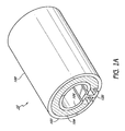
- Figure 1 is a perspective view of a system 10 comprising a tubular magnetic bearing structure 100 positioned proximally to a rail 120.
- the magnetic bearing structure 100 comprises a source of magnetic flux 104 between an inner shell 106 and an outer shell 102.
- the outer shell 102 has a C-shaped cross-section and is positioned concentrically about the inner shell 106, which has a similarly C-shaped cross-section.
- Both the inner shell 106 and outer shell 102 are preferably made from a magnetizable material, such as iron or steel.
- the shells 102, 106 may guide the magnetic flux of the source of magnetic flux 104 along the inner and outer perimeter of the magnetic bearing structure 100 and thereby assist in containing and concentrating the magnetic flux of the source of magnetic flux 104.
- the magnetic bearing structure 100 may support a load without contacting the rail 120. As described further with respect to Figure 3 , such a magnetic bearing structure 100 may be used to provide a levitative force countering the force of gravity upon a vehicle thereby reducing friction as the vehicle moves along the rail.
- the source of magnetic flux 104 comprises a single permanent magnet.
- Permanent magnets may comprise rare earth magnets, samarium-cobalt magnets, alnico magnets and neodymium magnets. The use of permanent magnets allows the bearing 100 to provide "always on" levitation forces which do not require an electric power source.
- the source of magnetic flux 104 may comprise one or more permanent magnets and/or one or more electromagnets.
- the source of magnetic flux 104 is uniformly radially magnetized, such that edge surfaces of the source of magnetic flux 104 contacting the outer shell 102 are of one polarity and edge surfaces of the source of magnetic flux 104 contacting the inner shell 106 are of an opposite polarity.
- the source of magnetic flux 104 may be a bonded magnet.
- a bonded magnet comprises a magnetic powder blended together with a thermoplastic resin to form injection molded, compression, or flexible magnets.
- the magnetic powder may be aligned in a preferred direction while the resin is liquid and be maintained in this preferred direction by the resin when it is hardened.
- a bonded magnet may be used to minimize stray flux, e.g., flux projecting outside the desired boundaries of the magnetic bearing 10.
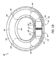
- Figure 1B is a cross-sectional view of the system of Figure 1A illustrating a plurality of magnetic field lines 190.
- the outer shell 102 comprises a first end 152 and a second end 154 located proximally to protrusions of the rail 120.
- the inner shell 106 also comprises a first end 162 and a second end 164 similarly located proximally to protrusions of the rail 120.
- the source of magnetic flux 104 generates a magnetic field represented by a plurality of magnetic field lines 190 beginning and ending at the source of magnetic flux 104.
- the outer shell 102 guides each field line 190 along the outer shell 102 to the first end 152 or second end 154 where it crosses the gap between the outer shell 102 and the rail 120.
- Each field line 190 continues via the rail 120 and exits the rail 120 by crossing the gap between the rail 120 and the first end 162 or second end 164 of the inner shell 106.
- the inner shell 106 guides each field line 190 along the inner shell 106 and each field line 190 ends back at the source of magnetic flux 104. Depending on the polarity of the source of magnetic flux 104, this order may be reversed.
- the length of the bearing 100 in the axial direction is larger than the radial thickness of the shell. This configuration minimizes non-suspensive flux and reduces stray fields as the lowest reluctance paths between the outer shell 102 and inner shell 106 are through the rail 120 via the gaps between the bearing 100 and the rail 120.
- the rail 120 illustrated in Figure 1 positioned between the first and second ends of the inner and outer shell has an I-shaped cross-section. In other embodiments, other shapes may be used. In one embodiment, the rail 120 is narrow enough to fit between the gaps between the first ends 152, 162 and second ends 154, 164. In one embodiment, the rail 120 is narrow enough to fit between the gaps between the first ends 152, 162 and second ends 154, 164 without contacting the magnetic bearing 100.
- the rail 120 may be of any axial length to allow propulsion in addition to levitation.
- the rail 120 comprises magnetizable material such as steel or iron. In another embodiment, the rail 120 comprises a magnetic material.
- the bearing 100 may "capture and restrain" the rail 120 since any vertical movement of the magnetic bearing structure 100 is resisted by magnetic forces generated by the source of magnetic flux 104 which tend to minimize the length of the magnetic field lines 190.
- the rail 120 comprises at least two substantially parallel rails separated by a gauge, each rail having a generally I-shaped profile with a head and a foot separated by a web.
- the rail 120 comprises standard or international gauge rails, e.g., the gauge is approximately 1,435 mm. The gauge may be smaller or larger than 1,435 mm.
- the rail 120 allow flanged wheels to ride along the head of the rail. Accordingly, embodiments described herein may be compatible with existing rail technology and other rolling stock.
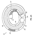
- Figure 2A is a front view of a system comprising a tubular magnetic bearing structure 200 having a control coil 225.
- the magnetic bearing structure 200 comprises a source of magnetic flux 204 between an inner shell 206 and an outer shell 202.
- the bearing 200 may "capture and restrain" the rail 220.
- control current in the control coil 225 changes the amount of flux and therefore force on each side of the gaps between the source of magnetic flux 204 and the rail 220 such that lateral forces may produced or controlled and contact prevented.
- a horizontal positioning system 210 may comprise a controller, processor, or other circuit, and may be configured to horizontally center the bearing 200 with respect to the rail 220.
- the horizontal positioning system 210 may comprise or be operative Iy coupled to a sensor 290 and a control coil 225.
- the control coil 225 may carry an electric current which generates a magnetic flux within the coil 225. Accordingly, the control coil 225 operates as an electromagnet, which converts an electric current into magnetic flux.
- the generated magnetic flux may bias the magnetic field described above with respect to Figure IB, thereby providing a horizontal force to the magnetic bearing structure 200 through differential flux control. Accordingly, the amount of magnetic flux is differentially modulated by adding the bias magnetic flux generated by the control coil 225 to the magnetic flux generated by the source of magnetic flux 104.
- the flux direction in the gap 187 between the rail and the outer shell 102 and the flux direction in the gap 188 between the rail and the inner shell 106 are in opposite directions because of the polarity and orientation of the source of magnetic flux. Accordingly, more than one control coil 225, where the direction of the coil winding for each coil is known or predetermined, may be used in series or parallel to appropriately produce net lateral force in the same direction.
- the horizontal positioning system 210 may horizontally center the bearing 200 on the rail 220.
- the horizontal positioning system 210 preserves a constant total air gap between the source of magnetic flux 204 and the rail 220 by balancing attractive horizontal forces between the source of magnetic flux 204 and the rail 220.
- the horizontal positioning system 210 operates to equalizes the magnetic flux on both sides of the rail 220.
- the sensor 290 may generate sensor data indicative of a distance from the sensor 290 to an object or to a predefined reference point.
- the sensor 290 may generate sensor data indicative of a horizontal position of the magnetic bearing structure 200 with respect to the rail 220.
- the sensor 290 may comprise, but is not limited to, an inductive proximity sensor, a capacitive displacement sensor, or a laser rangefinder.
- the sensor 290 emits a light or acoustic signal and measures changes in a returned field.
- the sensor 290 may also generate sensor data indicative of a rate of change of a distance from the sensor 290 to an object.
- the sensor 290 may generate sensor data indicative of how fast a magnetic bearing structure 200 is approaching a rail 220.
- the sensor 290 may comprise a Doppler-based sensor.
- the sensor 290 emits a light or acoustic signal and measures a change in the wavelength of a returned signal.
- the current carried by the control coil 225 as provided by the horizontal positioning system 210 is based on the horizontal position as determined by the sensor 290.
- the current is amplified based on a linear equation in which the current is linearly proportional to a distance indicated by the sensor 290.
- the current is amplified based on an inverse quadratic equation in which the current is proportional to the inverse of a square of a distance indicated by the sensor 290.
- the current is proportional, either linearly or non-linearly, to a difference in distances indicated by two sensors on opposite sides of the rail 220.
- the horizontal positioning system 210 may comprise a servo drive to efficiently perform in this feedback situation.
- a servo drive receives a command signal from a control system, amplifies the signal, and transmits electric current in order to produce motion proportional to the command signal.
- control coil 225 is wound around the outer shell 202. In another embodiment, the control coil 225 is wound around the inner shell 206. In another embodiment, multiple control coils may be wound around at least one of the outer shell 202 and inner shell 206. For example, in one embodiment, a first control coil is wound around the outer shell 202 and a second coil is wound around the inner shell 206. The control coil 225 may be physically separated from the outer shell 202, the source of magnetic flux 204, and the inner shell 206 by an electrically insulating material.
- FIG. 2B is a functional block diagram of a horizontal positioning system 210 according to one embodiment.
- the horizontal positioning system 210 receives a signal from the sensor 290 indicating the horizontal position of a bearing 200 with respect to a rail 220.
- a controller 212 processes the signal from the sensor 290 to determine the appropriate correcting current to provide to the control coil 225.
- the controller 212 controls (and may be powered by) a power source 216 such as a battery or other source of electric current.
- the controller 212 controls the power source 216 so as to provide a current to the control coil 225.
- the horizontal positioning system 210 comprises a memory 214 for storing an algorithm for determining an appropriate current based on the signal received from the sensor 290.
- the controller 212 may be a general purpose processor, a digital signal processor (DSP), an application specific integrated circuit (ASIC), a field programmable gate array (FPGA) or other programmable logic device, discrete gate or transistor logic, discrete hardware components, or any suitable combination thereof designed to perform the functions described herein.
- the controller 212 may also be implemented as a combination of computing devices, e.g., a combination of a DSP and a microprocessor, a plurality of microprocessors, one or more microprocessors in conjunction with a DSP core, or any other such configuration.
- the controller 212 may be coupled, via one or more buses, to read information from or write information to the memory 214.
- the controller 212 may additionally, or in the alternative, contain memory, such as processor registers.
- the memory 214 may include processor cache, including a multi-level hierarchical cache in which different levels have different capacities and access speeds.
- the memory 214 may also include random access memory (RAM), other volatile storage devices, or non-volatile storage devices.
- Figure 2C is flowchart illustrating a method 270 of providing a current to a control coil.
- the method 270 may be performed, for example, by the horizontal positioning system 210 of Figure 2B .
- the method 270 begins, in block 271, with the reception of sensor data indicative of a horizontal position.
- the sensor data is indicative of a distance from a sensor to an object or a predefined reference point.
- the sensor data is indicative of a horizontal position of a magnetic bearing with respect to a rail.
- the sensor data is indicative of a rate of change of a distance from a sensor to an object.
- the sensor data is indicative of how fast a magnetic bearing structure is approaching a rail.
- the sensor data comprises data from multiple sensors, each indicative of a distance or a rate of change of a distance.
- the method 200 determines whether the sensor data is indicative of a distance or speed greater than a predetermined threshold. The determination may be performed, for example, by the controller 212 of Figure 2B . In one embodiment, the predetermined threshold may be zero. If the distance or speed is less than the predetermined threshold, the method 200 moves to block 273 where the method 200 pauses for a predetermined amount of time. By including blocks 272 and 273, the method 270 does not perform a continuous adjustment which may be energy inefficient or may result in excess jerk.
- the method 200 continues to block 274, where a current corresponding to the received sensor data is determined.
- the determination may be performed, for example, by the controller 212 of Figure 2B .
- the current is amplified based on a linear equation in which the current is linearly proportional to a distance indicated by the sensor.
- the current is amplified based on an inverse quadratic equation in which the current is proportional to the inverse of a square of a distance indicated by the sensor.
- the current is proportional, either linearly or non-linearly, to a difference in distances indicated by two sensors on opposite sides of a rail.
- the current is amplified based on a look-up table.
- a look-up table may be stored, for example, in the memory 214 of Figure 2B .
- the current is determined proportional to a speed indicated by the sensor. In another embodiment, the current is determined based on a distance and a speed indicated by the sensor.
- the determined current is provided to one or more control coils.
- the current may be provided, for example, by the power source 216 as controlled by the controller 212 of Figure 2B .
- the current provided to the control coils may generate a magnetic flux within the control coil and thereby bias the magnetic field described above with respect to Figure 1B so as to provide a horizontal force and horizontally center the bearing on the rail.
- the determined current may be zero.
- the determined current may be zero when a magnetic bearing is centered with respect to a rail in the absence of external forces.
- the method 270 returns to block 271 and repeats.
- the method 270 continually provides a current based on sensor data.
- the horizontal positioning system 210 continually centers a magnetic bearing with respect to a rail.
- Figure 3 is a cross-sectional view of a system 30 comprising a vehicle 330 having a load 360 coupled to magnetic bearing structures 310, 312 positioned proximally to rails 320, 322.
- the vehicle comprises a first bearing 310 positioned proximally to the first rail 320 and a second bearing 312 positioned proximally to the second rail 322.
- the bearings 310, 312 provide a suspensive or levitative force counteracting the force of gravity acting upon the vehicle 330 and the load 360, thereby reducing friction along the rails.
- the bearings 310, 312 are attached to the load 360 via one or more support structures 362.
- the bearings may be attached via welding, screws, or other affixing techniques.
- a horizontal position system (not shown) comprising one or more position sensors and one or more control coils may keep the bearings horizontally centered such that the bearings do not contact the rails, further reducing friction.
- the horizontal positioning system comprises one or more control coils configured to respectively carry one or more electrical currents so as to provide a horizontal force as described above with respect to Figure 2 .
- the system may use asymmetrical air gaps as described in U.S. Patent App. No. 12/048,062 , herein incorporated by reference in its entirety.
- the inner gaps 380 between the bearings 310, 312 and the rails 320, 322 are of a different size than the outer gaps 382 between the bearings 310, 312 and the rails 320, 322. Thus, if the vehicle 330 is displaced horizontally, only one of the bearings would contact the rails.
- the system 30 may comprise bearings which provide a force in the vertical direction and a horizontal positioning system which provides a horizontal force
- the system 30 may also comprise an engine which provides a propulsive force in the direction of the rails 320, 322. Accordingly, the system 30 may be provided six degrees of freedom.
- the engine comprises a conventional, wheeled locomotive engine connected to the vehicle 330.
- the engine comprises a linear motor as described in U.S. Patent App. No. 12/048,062 or U.S. Patent No. 7,617,779 , herein incorporated by reference in its entirety.
- bearings 310, 312 are shown in Figure 3 , it is to be appreciated that a vehicle or system could contain additional independent bearings in various configurations.
- bearings may be approximately positioned at four corners of a vehicle.
- bearings having an approximate axial length similar to that of the vehicle may be positioned on each side of the vehicle.
- multiple vehicles having bearings may be pulled or pushed by one or more wheeled or levitating engines.
- a hybrid levitation system has the potential to be more energy efficient than conventional systems by virtue of the reduced friction.
- One embodiment of the invention comprises a MagLev system comprising one or more magnetic bearings.
- Figure 4 is a cross-sectional view of a system 40 comprising a prismatic magnetic bearing structure 400.
- the system 40 differs from the embodiments described above in that the magnetic bearing structure 400 is not tubular, but rather shaped as a prism. Although a rectangular prism is shown in Figure 4 , other shapes may be used. For example, in one embodiment, the cross-section of the magnetic bearing structure 400 is triangular. Otherwise, the structure and functionality of the system 40 may be as the system 20 of Figure 2 as described above. Because the magnetic bearing structure 400 is prismatic, the bearing 400 may be more easily attached to a vehicle or more easily stored. Because a prismatic structure generally contains flat surfaces, manufacture of a source of magnetic flux may be simplified and control coils may be more easily installed.
- Figure 5 is a cross-sectional view of another system 50 comprising a magnetic bearing structure 500.
- the system 50 differs from the embodiments described above in that the source of magnetic flux 504 comprises a plurality of magnets 504 arranged such that one polarity faces the outer shell 502 and the other polarity faces the inner shell 506. Between the magnets 504, there is a non-magnetizable substance 515, such as glass, wood, resin, or air and offering more space and potentially suitable locations for placement of control windings. Otherwise, the structure and functionality of the system 50 may be as the system 20 of Figure 2 as described above. Because the magnetic bearing structure 500 comprises a plurality of magnets 504 rather than a single magnet, the source of magnetic flux 504 may be less expensive. However, if the plurality of magnets 504 are too spaced apart, magnetic field lines may exist through the non-magnetizable material rather than through the rail 520 thereby decreasing the levitative force.
- the source of magnetic flux 504 comprises a plurality of magnets 504
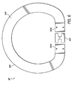
- Figure 6 is a cross-sectional view of a system comprising a magnetic bearing structure with two magnets.
- the magnetic bearing structure 600 comprises a support structure 630 and a source of magnetic flux comprising two magnets 604a, 604b arranged on either side of the rail 620.
- the magnets 604a, 604b are arranged such that the top of each magnet 604a, 604b is of one polarity and the bottom of each magnet 604a, 604b is of the other polarity.
- the support structure 360 fixes the location of the magnets 604a, 604b with respect to each other. Otherwise, the structure and functionality of the system 60 may be as the system 20 of Figure 2 as described above.
- magnetic bearing structure 600 has only two magnets, production may be simplified or costs may be reduced. However, magnetic field lines may exist to the left of the left magnet 604a or to the right of the right magnet 604b rather than through the rail 620 thereby decreasing the levitative force.
- the source of magnetic flux positioned proximally to the rail may be narrow in the vertical direction or may comprise narrow protrusions towards the rail so as to provide resistance to vertical displacement by reluctance changes.
Landscapes
- Engineering & Computer Science (AREA)
- Transportation (AREA)
- Mechanical Engineering (AREA)
- Physics & Mathematics (AREA)
- Electromagnetism (AREA)
- Power Engineering (AREA)
- Magnetic Bearings And Hydrostatic Bearings (AREA)
- Control Of Vehicles With Linear Motors And Vehicles That Are Magnetically Levitated (AREA)
- Linear Motors (AREA)
Description
-
- The invention generally relates to a method and system for transportation using a magnetic bearing structure. More particularly, the invention generally applies to levitation of a load for transportation. The preamble of Claim 1 as well as of Claim 12 is based on
US 2008/0223249 A1 that shows a magnetic suspension system with integrable propulsion. -
US 2008/0223249 A1 teaches magnetic levitation and control of a vehicle relative to a pair of rails by modulating flux in a frame. The frame comprises a front platform and a rear platform each connected by an upper and a lower axial crossbar. This system further comprises in one embodiment at least two lift generators, each comprising a source of magnetic flux in a rail via a leg on either side of the rail, at least one magnetically permeable beam connecting the lift generators, and control circuitry configured to generate and modulate a magnetic current flux through a crossbeam so as to maintain gaps between the legs and rail, wherein the gaps defined by the legs on either side of the rail are of equal size. Lateral control is produced by the flux of a control coil passing through inner gaps and/or outer gaps between the legs and rail. A magnetic connection between the two rails is conducted via a rail crossbar. Disadvantageously the frame with the platforms and axial crossbars inherently adds significant weight to the vehicle while due to the long flux paths used by the control fluxes the efficiency of the control currents is reduced. - Thus it is the aim of the current invention to overcome the disadvantages known from the state of the art and to provide a system for carrying a load along a magnetizable rail and a method of controlling a source of magnetic flux relative to a magnetizable rail, respectively, with enhanced guidance and controllability. Another aim of the invention is to provide a system with a magnetic bearing that can efficiently modulate vertical and lateral forces using short flux paths.
- In one aspect, an apparatus for carrying a load comprises a source of magnetic flux and a controller configured to control the position of the source of magnetic flux relative to a magnetizable structure. The source of magnetic flux comprises a first upper portion and a first lower portion of opposite polarities. The first portions are spaced apart horizontally from a first side of the magnetizable structure. The source of magnetic flux further comprises a second upper portion and a second lower portion of opposite polarities. The second portions are spaced apart horizontally from a second side of the magnetizable structure. The second side is opposite the first side. The first and second upper portions are magnetically attracted to an upper portion of the magnetizable structure and the first and second lower portions are magnetically attracted to a lower portion of the magnetizable structure.
-
-
Figure 1A is a perspective view of a system comprising a tubular magnetic bearing structure positioned proximally to a rail. -
Figure 1B is a cross-sectional view of the system ofFigure 1A illustrating a plurality of magnetic field lines representing a magnetic field. -
Figure 2A is a front view of a system comprising a tubular magnetic bearing structure having a control coil. -
Figure 2B is a functional block diagram of a horizontal positioning system. -
Figure 2C is a flowchart illustrating a method of providing a current to a control coil based on received sensor data. -
Figure 3 is a cross-sectional view of a system comprising a vehicle with magnetic bearing structures positioned proximally to rails. -
Figure 4 is a cross-sectional view of a system comprising a prismatic magnetic bearing structure. -
Figure 5 is a cross-sectional view of a system comprising a magnetic bearing structure with a plurality of magnets. -
Figure 6 is a cross-sectional view of a not claimed system comprising a magnetic bearing structure with two magnets. - The following detailed description is directed to certain specific aspects of the invention. However, the invention may be embodied in a multitude of different ways, for example, as defined and covered by the claims. It should be apparent that the aspects herein may be embodied in a wide variety of forms and that any specific structure, function, or both being disclosed herein is merely representative. Based on the teachings herein one skilled in the art should appreciate that an aspect disclosed herein may be implemented independently of any other aspects and that two or more of these aspects may be combined in various ways. For example, an apparatus may be implemented or a method may be practiced using any number of the aspects set forth herein. In addition, such an apparatus may be implemented or such a method may be practiced using other structure, functionality, or structure and functionality in addition to or other than one or more of the aspects set forth herein. Similarly, methods disclosed herein may be performed by one or more computer processors configured to execute instructions retrieved from a computer-readable storage medium. A computer-readable storage medium stores information, such as data or instructions, for some interval of time, such that the information may be read by a computer during that interval of time. Examples of computer-readable storage media are memory, such as random access memory (RAM), and storage, such as hard drives, optical discs, flash memory, floppy disks, magnetic tape, paper tape, and punch cards.
-
Figure 1 is a perspective view of a system 10 comprising a tubular magnetic bearingstructure 100 positioned proximally to arail 120. Themagnetic bearing structure 100 comprises a source ofmagnetic flux 104 between aninner shell 106 and anouter shell 102. In one embodiment, theouter shell 102 has a C-shaped cross-section and is positioned concentrically about theinner shell 106, which has a similarly C-shaped cross-section. Both theinner shell 106 andouter shell 102 are preferably made from a magnetizable material, such as iron or steel. Theshells magnetic flux 104 along the inner and outer perimeter of themagnetic bearing structure 100 and thereby assist in containing and concentrating the magnetic flux of the source ofmagnetic flux 104. - Because of the magnetic attraction between the
magnetic bearing structure 100 and therail 120, themagnetic bearing structure 100 may support a load without contacting therail 120. As described further with respect toFigure 3 , such a magnetic bearingstructure 100 may be used to provide a levitative force countering the force of gravity upon a vehicle thereby reducing friction as the vehicle moves along the rail. - In one embodiment, the source of
magnetic flux 104 comprises a single permanent magnet. Permanent magnets may comprise rare earth magnets, samarium-cobalt magnets, alnico magnets and neodymium magnets. The use of permanent magnets allows the bearing 100 to provide "always on" levitation forces which do not require an electric power source. In other embodiments, the source ofmagnetic flux 104 may comprise one or more permanent magnets and/or one or more electromagnets. In one embodiment, the source ofmagnetic flux 104 is uniformly radially magnetized, such that edge surfaces of the source ofmagnetic flux 104 contacting theouter shell 102 are of one polarity and edge surfaces of the source ofmagnetic flux 104 contacting theinner shell 106 are of an opposite polarity. The source ofmagnetic flux 104 may be a bonded magnet. In one embodiment, a bonded magnet comprises a magnetic powder blended together with a thermoplastic resin to form injection molded, compression, or flexible magnets. The magnetic powder may be aligned in a preferred direction while the resin is liquid and be maintained in this preferred direction by the resin when it is hardened. A bonded magnet may be used to minimize stray flux, e.g., flux projecting outside the desired boundaries of the magnetic bearing 10. -
Figure 1B is a cross-sectional view of the system ofFigure 1A illustrating a plurality ofmagnetic field lines 190. Although only sixfield lines 190 are illustrated, it is to be appreciated that the magnetic field is a continuous field and more orfewer field lines 190 could be used to represent it. Theouter shell 102 comprises afirst end 152 and asecond end 154 located proximally to protrusions of therail 120. Theinner shell 106 also comprises afirst end 162 and asecond end 164 similarly located proximally to protrusions of therail 120. In one embodiment, the source ofmagnetic flux 104 generates a magnetic field represented by a plurality ofmagnetic field lines 190 beginning and ending at the source ofmagnetic flux 104. Theouter shell 102 guides eachfield line 190 along theouter shell 102 to thefirst end 152 orsecond end 154 where it crosses the gap between theouter shell 102 and therail 120. Eachfield line 190 continues via therail 120 and exits therail 120 by crossing the gap between therail 120 and thefirst end 162 orsecond end 164 of theinner shell 106. Theinner shell 106 guides eachfield line 190 along theinner shell 106 and eachfield line 190 ends back at the source ofmagnetic flux 104. Depending on the polarity of the source ofmagnetic flux 104, this order may be reversed. - In one embodiment, the length of the
bearing 100 in the axial direction (along the rail 120) is larger than the radial thickness of the shell. This configuration minimizes non-suspensive flux and reduces stray fields as the lowest reluctance paths between theouter shell 102 andinner shell 106 are through therail 120 via the gaps between the bearing 100 and therail 120. - The
rail 120 illustrated inFigure 1 positioned between the first and second ends of the inner and outer shell has an I-shaped cross-section. In other embodiments, other shapes may be used. In one embodiment, therail 120 is narrow enough to fit between the gaps between the first ends 152, 162 and second ends 154, 164. In one embodiment, therail 120 is narrow enough to fit between the gaps between the first ends 152, 162 and second ends 154, 164 without contacting themagnetic bearing 100. Therail 120 may be of any axial length to allow propulsion in addition to levitation. - In one embodiment, the
rail 120 comprises magnetizable material such as steel or iron. In another embodiment, therail 120 comprises a magnetic material. Thebearing 100 may "capture and restrain" therail 120 since any vertical movement of themagnetic bearing structure 100 is resisted by magnetic forces generated by the source ofmagnetic flux 104 which tend to minimize the length of the magnetic field lines 190. - In one embodiment, the
rail 120 comprises at least two substantially parallel rails separated by a gauge, each rail having a generally I-shaped profile with a head and a foot separated by a web. In one embodiment, therail 120 comprises standard or international gauge rails, e.g., the gauge is approximately 1,435 mm. The gauge may be smaller or larger than 1,435 mm. In one embodiment, therail 120 allow flanged wheels to ride along the head of the rail. Accordingly, embodiments described herein may be compatible with existing rail technology and other rolling stock. -
Figure 2A is a front view of a system comprising a tubularmagnetic bearing structure 200 having acontrol coil 225. Themagnetic bearing structure 200 comprises a source ofmagnetic flux 204 between aninner shell 206 and anouter shell 202. As described above with respect to the system 10 ofFigure 1 , thebearing 200 may "capture and restrain" therail 220. As described further below, control current in thecontrol coil 225 changes the amount of flux and therefore force on each side of the gaps between the source ofmagnetic flux 204 and therail 220 such that lateral forces may produced or controlled and contact prevented. - A
horizontal positioning system 210 may comprise a controller, processor, or other circuit, and may be configured to horizontally center the bearing 200 with respect to therail 220. Thehorizontal positioning system 210 may comprise or be operative Iy coupled to asensor 290 and acontrol coil 225. Thecontrol coil 225 may carry an electric current which generates a magnetic flux within thecoil 225. Accordingly, thecontrol coil 225 operates as an electromagnet, which converts an electric current into magnetic flux. The generated magnetic flux may bias the magnetic field described above with respect to Figure IB, thereby providing a horizontal force to themagnetic bearing structure 200 through differential flux control. Accordingly, the amount of magnetic flux is differentially modulated by adding the bias magnetic flux generated by thecontrol coil 225 to the magnetic flux generated by the source ofmagnetic flux 104. As can be seen in Figure IB, the flux direction in thegap 187 between the rail and theouter shell 102 and the flux direction in thegap 188 between the rail and theinner shell 106 are in opposite directions because of the polarity and orientation of the source of magnetic flux. Accordingly, more than onecontrol coil 225, where the direction of the coil winding for each coil is known or predetermined, may be used in series or parallel to appropriately produce net lateral force in the same direction. - Through control of the current through the
control coil 225, thehorizontal positioning system 210 may horizontally center the bearing 200 on therail 220. In one embodiment, thehorizontal positioning system 210 preserves a constant total air gap between the source ofmagnetic flux 204 and therail 220 by balancing attractive horizontal forces between the source ofmagnetic flux 204 and therail 220. In particular, because the magnetic attraction pulls both ends of eachshell rail 220, the effectiveness of the control is enhanced. In one embodiment, thehorizontal positioning system 210 operates to equalizes the magnetic flux on both sides of therail 220. - In order to determine the horizontal position, one or
more sensors 290 may be used. Thesensor 290 may generate sensor data indicative of a distance from thesensor 290 to an object or to a predefined reference point. For example, thesensor 290 may generate sensor data indicative of a horizontal position of themagnetic bearing structure 200 with respect to therail 220. Thesensor 290 may comprise, but is not limited to, an inductive proximity sensor, a capacitive displacement sensor, or a laser rangefinder. In one embodiment, thesensor 290 emits a light or acoustic signal and measures changes in a returned field. In another embodiment, thesensor 290 may also generate sensor data indicative of a rate of change of a distance from thesensor 290 to an object. For example, thesensor 290 may generate sensor data indicative of how fast amagnetic bearing structure 200 is approaching arail 220. Thesensor 290 may comprise a Doppler-based sensor. In one embodiment, thesensor 290 emits a light or acoustic signal and measures a change in the wavelength of a returned signal. - In one embodiment, the current carried by the
control coil 225 as provided by thehorizontal positioning system 210 is based on the horizontal position as determined by thesensor 290. In one embodiment, the current is amplified based on a linear equation in which the current is linearly proportional to a distance indicated by thesensor 290. In another embodiment, the current is amplified based on an inverse quadratic equation in which the current is proportional to the inverse of a square of a distance indicated by thesensor 290. In another embodiment, the current is proportional, either linearly or non-linearly, to a difference in distances indicated by two sensors on opposite sides of therail 220. Because the current is based, at least in part, on a measurement from thesensor 290, which is based, at least in part on the current provided, thehorizontal positioning system 210 may comprise a servo drive to efficiently perform in this feedback situation. In general, a servo drive receives a command signal from a control system, amplifies the signal, and transmits electric current in order to produce motion proportional to the command signal. - In one embodiment, the
control coil 225 is wound around theouter shell 202. In another embodiment, thecontrol coil 225 is wound around theinner shell 206. In another embodiment, multiple control coils may be wound around at least one of theouter shell 202 andinner shell 206. For example, in one embodiment, a first control coil is wound around theouter shell 202 and a second coil is wound around theinner shell 206. Thecontrol coil 225 may be physically separated from theouter shell 202, the source ofmagnetic flux 204, and theinner shell 206 by an electrically insulating material. -
Figure 2B is a functional block diagram of ahorizontal positioning system 210 according to one embodiment. Thehorizontal positioning system 210 receives a signal from thesensor 290 indicating the horizontal position of abearing 200 with respect to arail 220. Acontroller 212 processes the signal from thesensor 290 to determine the appropriate correcting current to provide to thecontrol coil 225. Thecontroller 212 controls (and may be powered by) apower source 216 such as a battery or other source of electric current. Thecontroller 212 controls thepower source 216 so as to provide a current to thecontrol coil 225. In one embodiment, thehorizontal positioning system 210 comprises amemory 214 for storing an algorithm for determining an appropriate current based on the signal received from thesensor 290. - The
controller 212 may be a general purpose processor, a digital signal processor (DSP), an application specific integrated circuit (ASIC), a field programmable gate array (FPGA) or other programmable logic device, discrete gate or transistor logic, discrete hardware components, or any suitable combination thereof designed to perform the functions described herein. Thecontroller 212 may also be implemented as a combination of computing devices, e.g., a combination of a DSP and a microprocessor, a plurality of microprocessors, one or more microprocessors in conjunction with a DSP core, or any other such configuration. - The
controller 212 may be coupled, via one or more buses, to read information from or write information to thememory 214. Thecontroller 212 may additionally, or in the alternative, contain memory, such as processor registers. Thememory 214 may include processor cache, including a multi-level hierarchical cache in which different levels have different capacities and access speeds. Thememory 214 may also include random access memory (RAM), other volatile storage devices, or non-volatile storage devices. -
Figure 2C is flowchart illustrating amethod 270 of providing a current to a control coil. Themethod 270 may be performed, for example, by thehorizontal positioning system 210 ofFigure 2B . Themethod 270 begins, inblock 271, with the reception of sensor data indicative of a horizontal position. In one embodiment, the sensor data is indicative of a distance from a sensor to an object or a predefined reference point. For example, in one embodiment, the sensor data is indicative of a horizontal position of a magnetic bearing with respect to a rail. In one embodiment, the sensor data is indicative of a rate of change of a distance from a sensor to an object. For example, in one embodiment, the sensor data is indicative of how fast a magnetic bearing structure is approaching a rail. In another embodiment, the sensor data comprises data from multiple sensors, each indicative of a distance or a rate of change of a distance. - Next, in
block 272, it is determined whether the sensor data is indicative of a distance or speed greater than a predetermined threshold. The determination may be performed, for example, by thecontroller 212 ofFigure 2B . In one embodiment, the predetermined threshold may be zero. If the distance or speed is less than the predetermined threshold, themethod 200 moves to block 273 where themethod 200 pauses for a predetermined amount of time. By includingblocks method 270 does not perform a continuous adjustment which may be energy inefficient or may result in excess jerk. - If it is determined that the sensor data is indicative of a distance or speed greater than the predetermined threshold, the
method 200 continues to block 274, where a current corresponding to the received sensor data is determined. The determination may be performed, for example, by thecontroller 212 ofFigure 2B . In one embodiment, the current is amplified based on a linear equation in which the current is linearly proportional to a distance indicated by the sensor. In another embodiment, the current is amplified based on an inverse quadratic equation in which the current is proportional to the inverse of a square of a distance indicated by the sensor. In another embodiment, the current is proportional, either linearly or non-linearly, to a difference in distances indicated by two sensors on opposite sides of a rail. In yet another embodiment, the current is amplified based on a look-up table. Such a look-up table may be stored, for example, in thememory 214 ofFigure 2B . In one embodiment, the current is determined proportional to a speed indicated by the sensor. In another embodiment, the current is determined based on a distance and a speed indicated by the sensor. - Continuing to block 275, the determined current is provided to one or more control coils. The current may be provided, for example, by the
power source 216 as controlled by thecontroller 212 ofFigure 2B . The current provided to the control coils may generate a magnetic flux within the control coil and thereby bias the magnetic field described above with respect toFigure 1B so as to provide a horizontal force and horizontally center the bearing on the rail. It is to be appreciated that in some embodiments, the determined current may be zero. For example, the determined current may be zero when a magnetic bearing is centered with respect to a rail in the absence of external forces. - After
block 275, themethod 270 returns to block 271 and repeats. Thus, themethod 270 continually provides a current based on sensor data. In one embodiment, thehorizontal positioning system 210 continually centers a magnetic bearing with respect to a rail. -
Figure 3 is a cross-sectional view of a system 30 comprising avehicle 330 having aload 360 coupled tomagnetic bearing structures rails 320, 322. By using two rails rather than a single rail, rotation of the vehicle with respect to the rail may be inhibited. The vehicle comprises afirst bearing 310 positioned proximally to thefirst rail 320 and asecond bearing 312 positioned proximally to the second rail 322. Thebearings vehicle 330 and theload 360, thereby reducing friction along the rails. Thebearings load 360 via one ormore support structures 362. The bearings may be attached via welding, screws, or other affixing techniques. - A horizontal position system (not shown) comprising one or more position sensors and one or more control coils may keep the bearings horizontally centered such that the bearings do not contact the rails, further reducing friction. In one embodiment, the horizontal positioning system comprises one or more control coils configured to respectively carry one or more electrical currents so as to provide a horizontal force as described above with respect to
Figure 2 . - In one embodiment, the system may use asymmetrical air gaps as described in
U.S. Patent App. No. 12/048,062 , herein incorporated by reference in its entirety. In one embodiment, theinner gaps 380 between thebearings rails 320, 322 are of a different size than theouter gaps 382 between thebearings rails 320, 322. Thus, if thevehicle 330 is displaced horizontally, only one of the bearings would contact the rails. - Whereas the system 30 may comprise bearings which provide a force in the vertical direction and a horizontal positioning system which provides a horizontal force, the system 30 may also comprise an engine which provides a propulsive force in the direction of the
rails 320, 322. Accordingly, the system 30 may be provided six degrees of freedom. In one embodiment, the engine comprises a conventional, wheeled locomotive engine connected to thevehicle 330. In another embodiment, the engine comprises a linear motor as described inU.S. Patent App. No. 12/048,062 orU.S. Patent No. 7,617,779 , herein incorporated by reference in its entirety. - Although only two
bearings Figure 3 , it is to be appreciated that a vehicle or system could contain additional independent bearings in various configurations. For example, bearings may be approximately positioned at four corners of a vehicle. As another example, bearings having an approximate axial length similar to that of the vehicle may be positioned on each side of the vehicle. In one embodiment, multiple vehicles having bearings may be pulled or pushed by one or more wheeled or levitating engines. - Some of the benefits of levitating platforms, such as the
vehicle 330 ofFigure 3 , as opposed to wheeled carts are, among other things, the reduction of wear on mechanical parts, the reduction of extraneous heat produced, and the reduction of noise. A hybrid levitation system has the potential to be more energy efficient than conventional systems by virtue of the reduced friction. One embodiment of the invention comprises a MagLev system comprising one or more magnetic bearings. -
Figure 4 is a cross-sectional view of a system 40 comprising a prismaticmagnetic bearing structure 400. The system 40 differs from the embodiments described above in that themagnetic bearing structure 400 is not tubular, but rather shaped as a prism. Although a rectangular prism is shown inFigure 4 , other shapes may be used. For example, in one embodiment, the cross-section of themagnetic bearing structure 400 is triangular. Otherwise, the structure and functionality of the system 40 may be as the system 20 ofFigure 2 as described above. Because themagnetic bearing structure 400 is prismatic, thebearing 400 may be more easily attached to a vehicle or more easily stored. Because a prismatic structure generally contains flat surfaces, manufacture of a source of magnetic flux may be simplified and control coils may be more easily installed. -
Figure 5 is a cross-sectional view of another system 50 comprising a magnetic bearing structure 500. The system 50 differs from the embodiments described above in that the source ofmagnetic flux 504 comprises a plurality ofmagnets 504 arranged such that one polarity faces theouter shell 502 and the other polarity faces theinner shell 506. Between themagnets 504, there is anon-magnetizable substance 515, such as glass, wood, resin, or air and offering more space and potentially suitable locations for placement of control windings. Otherwise, the structure and functionality of the system 50 may be as the system 20 ofFigure 2 as described above. Because the magnetic bearing structure 500 comprises a plurality ofmagnets 504 rather than a single magnet, the source ofmagnetic flux 504 may be less expensive. However, if the plurality ofmagnets 504 are too spaced apart, magnetic field lines may exist through the non-magnetizable material rather than through therail 520 thereby decreasing the levitative force. -
Figure 6 is a cross-sectional view of a system comprising a magnetic bearing structure with two magnets. Themagnetic bearing structure 600 comprises asupport structure 630 and a source of magnetic flux comprising twomagnets 604a, 604b arranged on either side of therail 620. Themagnets 604a, 604b are arranged such that the top of eachmagnet 604a, 604b is of one polarity and the bottom of eachmagnet 604a, 604b is of the other polarity. In one embodiment, thesupport structure 360 fixes the location of themagnets 604a, 604b with respect to each other. Otherwise, the structure and functionality of thesystem 60 may be as the system 20 ofFigure 2 as described above. Because themagnetic bearing structure 600 has only two magnets, production may be simplified or costs may be reduced. However, magnetic field lines may exist to the left of the left magnet 604a or to the right of theright magnet 604b rather than through therail 620 thereby decreasing the levitative force. - In one embodiment, the source of magnetic flux positioned proximally to the rail may be narrow in the vertical direction or may comprise narrow protrusions towards the rail so as to provide resistance to vertical displacement by reluctance changes.
- While the above description has pointed out novel features of the invention as applied to various embodiments, the skilled person will understand that various omissions, substitutions, and changes in the form and details of the device or process illustrated may be made without departing from the scope of the invention.
Claims (15)
- A system (10, 20, 30, 40, 50) for carrying a load (360) along a magnetizable rail (120, 220, 320, 420, 520) having an upper portion, a lower portion, a first side, and a second side opposite to the first side, the system comprising:- a source of magnetic flux (104, 204, 404, 504) having an inner surface and an outer surface, and- a controller (212) configured to control a position of the source of magnetic flux (104, 204, 404, 504) relative to the magnetizable rail (120, 220, 320, 420, 520),characterized in that
the source of magnetic flux (104, 204, 404, 504) comprises- a first end (162) of an inner shell (106, 206, 406, 506) having a first polarity and a first end (152) of an outer shell (102, 202, 402, 502) having a second polarity opposite of the first polarity, wherein the first end (162) of the inner shell and the first end (152) of the outer shell are configured to be spaced apart (187, 188) from the first side of the magnetizable rail (120, 220, 320, 420, 520); and- a second end (164) of the inner shell (106, 206, 406, 506) having the first polarity and a second end (154) of the outer shell (102, 202, 402, 502) having the second polarity, wherein the second end (164) of the inner shell and the second end (154) of the outer shell are configured to be spaced apart (187, 188) from the second side of the magnetizable rail (120, 220, 320, 420, 520), and wherein the first end (162) and the second end (164) of the inner shell are configured to be magnetically attracted to the upper portion of the magnetizable rail (120, 220, 320, 420, 520 ) and the first end (152) and the second end (154) of the outer shell are configured to be magnetically attracted to the lower portion of the magnetizable rail (120, 220, 320, 420, 520); wherein- the inner shell (106, 206, 406, 506) is attached as a first flux guide to the inner surface of the source of magnetic flux (104, 204, 404, 504), the inner shell (106, 206, 406, 506) comprising a first magnetizable material and- the outer shell (102, 202, 402, 502) is attached as a second flux guide to the outer surface of the source of magnetic flux (104, 204, 404, 504), the outer shell (102, 202, 402, 502) comprising a second magnetizable material. - The system (10, 20, 30, 40, 50) of Claim 1, wherein the source of magnetic flux (104, 504) comprises at least one of the following: one or more permanent magnets (104, 504), a plurality of sources of magnetic flux (504) separated by non-magnetizable substances (515), a bonded magnet (104), and a uniformly radially magnetized magnet (104).
- The system (10, 20, 30, 40, 50) of Claim 1, wherein each of the inner shell (106, 206, 406, 506) as first flux guide and the outer shell (102, 202, 402, 502) as second flux guide is configured to concentrate a magnetic flux generated by the source of magnetic flux (104, 204, 404, 504).
- The system (10, 20, 30, 40, 50) of Claim 1, wherein the controller (212) comprises a control coil (225) configured to carry an electric current to bias a magnetic flux generated by the source of magnetic flux.
- The system (10, 20, 30, 40, 50) of Claim 1, wherein the controller (212) further comprises:- one or more sensors (290) configured to generate sensor data indicative of a position of at least one of the portions of the source of magnetic flux relative to the magnetizable rail; and- a circuit configured to provide a current based on the sensor data.
- The system (10, 20, 30, 40, 50) of Claim 5, wherein at least one of the sensors (290) is configured to determine a gap (187, 188) distance between the source of magnetic flux and the magnetizable rail.
- The system (10, 20, 30, 40, 50) of Claim 5, wherein the current is configured to equalize a magnetic flux on both sides of the magnetizable rail.
- The system (10, 20, 30, 40, 50) of Claim 5, wherein the current generates a bias magnetic flux to increase or decrease a magnetic flux generated by the source of magnetic flux.
- The system (10, 20, 30, 40, 50) of Claim 1, further comprising an engine configured to provide a propulsive force along the magnetizable rail.
- The system (30) of Claim 1, further comprising an additional source of magnetic flux for use with an additional magnetizable rail (322) having an upper portion, a lower portion, a first side, and a second side opposite to the first side, the additional source of magnetic flux comprising:- an additional first end of an inner shell having the first polarity and an additional first end of an outer shell having the second polarity, wherein the additional first end of the inner shell and the additional first end of the outer shell are configured to be spaced (380) apart from the first side of the additional magnetizable rail (322); and- an additional second end of an inner shell having the first polarity and an additional second end of an outer shell having the second polarity, wherein the additional second end of an inner shell and the additional second end of an outer shell are configured to be spaced apart (382) from the second side of the additional magnetizable rail (322), wherein the first end and the second end of the inner shell are configured to be magnetically attracted to the upper portion of the additional magnetizable rail and the first end and the second end of the outer shell are configured to be magnetically attracted to the lower portion of the additional magnetizable rail, wherein the magnetizable rail (320) and the additional magnetizable rail (322) are spaced apart from one another.
- The system (10, 20, 30, 40, 50) of Claim 1, wherein the first end of the inner shell (106, 206, 406, 506) is configured to inject a magnetic flux into the upper portion of the magnetizable rail on the first side, wherein the second end of the inner shell (106, 206, 406, 506) is configured to inject the magnetic flux into the upper portion of the magnetizable rail on the second side, wherein the magnetic flux is conducted in the magnetizable rail to the lower portion, wherein at least a portion of the magnetic flux is to returned to the first end of the outer shell (102, 202, 402, 502) via the lower portion of the magnetizable rail on the first side, and wherein at least a portion of the magnetic flux is returned to the second end of the outer shell (102, 202, 402, 502) via the lower portion of the magnetizable rail on the second side.
- A method of controlling a source of magnetic flux (104, 204, 404, 504) relative to a magnetizable rail (120, 220, 320, 420, 520) having an upper portion, a lower portion, a first side, and a second side opposite to the first side, the method comprising:- providing a source of magnetic flux (104, 204, 404, 504) having an inner surface and an outer surface, and- controlling a position of the source of magnetic flux (104, 204, 404, 504) relative to the magnetizable rail (120, 220, 320, 420, 520),
characterized in that- the source of magnetic flux (104, 204, 404, 504) comprises a first end (162) of an inner shell (106, 206, 406, 506) having a first polarity, a first end (152) of an outer shell (102, 202, 402, 502) having a second polarity opposite of the first polarity, a second end (164) of the inner shell having the first polarity, and a second end (154) of the outer shell having the second polarity,;- positioning the first end (162) of the inner shell of the source of magnetic flux (104, 204, 404, 504) and the first end (152) of the outer shell of the source of magnetic flux apart from the first side of the magnetizable rail (120, 220, 320, 420, 520);- positioning the second end (164) of the inner shell of the source of magnetic flux (104, 204, 404, 504) and the second end (154) of the outer shell of the source of magnetic flux apart from the second side of the magnetizable rail (120, 220, 320, 420, 520), wherein the first end and the second end of the inner shell are magnetically attracted to the upper portion of the magnetizable rail (120, 220, 320, 420, 520) and the first end and the second end of the outer shell are magnetically attracted to the lower portion of the magnetizable rail (120, 220, 320, 420, 520); wherein- the inner shell (106, 206, 406, 506) as a first flux guide comprising a first magnetizable material and being attached to the inner surface of the source of magnetic flux (104, 204, 404, 504), and- the outer shell (102, 202, 402, 502) as a second flux guide comprising a second magnetizable material and being attached to the outer surface of the source of magnetic flux
for guiding the magnetic flux of the source of magnetic flux (104, 204, 404, 504) along an inner and outer perimeter of an magnetic bearing structure (100, 200, 310, 312, 400, 500) and thereby assisting in containing and concentrating the magnetic flux of the source of magnetic flux (104, 204, 404, 504). - The method of Claim 12, wherein controlling the position comprises sensing the position of at least one of the portions of the source of magnetic flux (104, 204, 404, 504) relative to the magnetizable rail (120, 220, 320, 420, 520), and providing a current based on the sensed position.
- The method of Claim 13, wherein sensing the position comprises determining a gap distance (187, 188, 380, 382) between the source of magnetic flux (104, 204, 404, 504) and the magnetizable rail (120, 220, 320, 420, 520).
- The method of Claim 12, wherein controlling the position comprises equalizing the magnetic flux on both sides of the magnetizable rail (120, 220, 320, 420, 520).
Applications Claiming Priority (2)
| Application Number | Priority Date | Filing Date | Title |
|---|---|---|---|
| US16377809P | 2009-03-26 | 2009-03-26 | |
| PCT/US2010/028746 WO2010111549A2 (en) | 2009-03-26 | 2010-03-25 | Method and system for transportation using a magnetic bearing structure |
Publications (2)
| Publication Number | Publication Date |
|---|---|
| EP2411241A2 EP2411241A2 (en) | 2012-02-01 |
| EP2411241B1 true EP2411241B1 (en) | 2014-06-04 |
Family
ID=42781892
Family Applications (1)
| Application Number | Title | Priority Date | Filing Date |
|---|---|---|---|
| EP10737659.2A Not-in-force EP2411241B1 (en) | 2009-03-26 | 2010-03-25 | Method and system for transportation using a magnetic bearing structure |
Country Status (9)
| Country | Link |
|---|---|
| US (1) | US8324777B2 (en) |
| EP (1) | EP2411241B1 (en) |
| JP (1) | JP5628285B2 (en) |
| KR (1) | KR101581074B1 (en) |
| CN (1) | CN102395486B (en) |
| AU (1) | AU2010229810B2 (en) |
| BR (1) | BRPI1013875B1 (en) |
| RU (1) | RU2520827C2 (en) |
| WO (1) | WO2010111549A2 (en) |
Families Citing this family (4)
| Publication number | Priority date | Publication date | Assignee | Title |
|---|---|---|---|---|
| US8850989B2 (en) * | 2010-12-03 | 2014-10-07 | Sandor Wayne Shapery | Magnetic levitation assembly |
| US8820246B2 (en) * | 2011-12-16 | 2014-09-02 | Sandor Wayne Shapery | Method and system for transportation using a rail structure |
| RU2573524C1 (en) * | 2014-05-28 | 2016-01-20 | Акционерное общество "НИИЭФА им. Д.В. Ефремова" (АО "НИИЭФА") | Combined magnetic suspension of vehicle |
| RU2739939C1 (en) * | 2020-05-08 | 2020-12-30 | Акционерное Общество "Нииэфа Им. Д.В. Ефремова" | Hybrid electromagnet for maglev system |
Family Cites Families (44)
| Publication number | Priority date | Publication date | Assignee | Title |
|---|---|---|---|---|
| US3569804A (en) | 1968-08-20 | 1971-03-09 | Nasa | Direct current motor with stationary armature and field |
| JPS5419962B1 (en) * | 1969-02-24 | 1979-07-19 | ||
| DE2021834C3 (en) * | 1970-05-05 | 1974-05-09 | Messerschmitt-Boelkow-Blohm Gmbh, 8000 Muenchen | Magnetic levitation train |
| JPS4831643B1 (en) * | 1970-06-11 | 1973-10-01 | ||
| US3694041A (en) * | 1971-01-08 | 1972-09-26 | Nasa | Electric motive machine including magnetic bearing |
| DE2134425B2 (en) * | 1971-07-09 | 1973-09-27 | Krauss-Maffei Ag, 8000 Muenchen | Electromagnetic support and guidance system |
| DE2146143A1 (en) * | 1971-09-15 | 1973-03-22 | Krauss Maffei Ag | ELECTROMAGNETIC SUPPORT OR GUIDANCE SYSTEM |
| BE792719A (en) * | 1971-12-16 | 1973-03-30 | Siemens Ag | SANSCONTACT ELECTRODYNAMIC SUPPORT AND GUIDANCE DEVICE, IN PARTICULAR FOR VEHICLES, |
| DE2220735A1 (en) * | 1972-01-20 | 1973-11-08 | Krauss Maffei Ag | ARRANGEMENT FOR NON-CONTACT MAGNETIC CARRYING OF A HOVER VEHICLE IN THE AREA OF A ROAD BREAKING |
| DE2337930C3 (en) * | 1972-07-27 | 1979-11-22 | Japanese National Railways | Electromagnetic rail of a thyristor-controlled linear motor for driving a train |
| CH566666A5 (en) * | 1972-12-30 | 1975-09-15 | Krauss Maffei Ag | |
| JPS5226364B2 (en) * | 1973-08-10 | 1977-07-13 | ||
| US3976339A (en) * | 1974-01-14 | 1976-08-24 | Sperry Rand Corporation | Magnetic suspension apparatus |
| JPS5277314A (en) * | 1975-12-23 | 1977-06-29 | Japanese National Railways<Jnr> | Guide system for linear motor car |
| US4315197A (en) * | 1980-02-07 | 1982-02-09 | The United States Of America As Represented By The Administrator Of The National Aeronautics And Space Administration | Linear magnetic motor/generator |
| US4324185A (en) * | 1980-07-21 | 1982-04-13 | Vinson Roy D | Permanent-magnet-levitated transportation system |
| JPS58144503A (en) * | 1982-02-22 | 1983-08-27 | Mitsubishi Electric Corp | Magnetically floating vehicle |
| DE3432467C1 (en) * | 1984-09-04 | 1986-03-27 | Kernforschungsanlage Jülich GmbH, 5170 Jülich | Rod and crucible holder |
| US4634191A (en) * | 1985-11-21 | 1987-01-06 | The United States Of America As Represented By The Administrator Of The National Aeronautics & Space Administration | Radial and torsionally controlled magnetic bearing |
| SU1372782A1 (en) * | 1985-12-11 | 1995-06-27 | Всесоюзный научно-исследовательский, проектно-конструкторский и технологический институт электровозостроения | Magnet for magnetic suspension and guiding system |
| DE3635258C1 (en) * | 1986-02-27 | 1987-10-01 | Peter Schuster | Magnetic force system for low-friction transport of loads |
| JPH07123321B2 (en) * | 1986-12-10 | 1995-12-25 | 住友電気工業株式会社 | Suction type magnetic levitation guide device |
| US4806208A (en) | 1987-10-14 | 1989-02-21 | Asten Group, Inc. | Method of seaming a seamed felt on a papermaking machine with oppositely tapered pintle elements |
| US5360470A (en) * | 1992-07-06 | 1994-11-01 | Fujitsu Limited | Magnetic levitating transporting apparatus with a movable magnetic unit |
| US5372636A (en) * | 1993-01-22 | 1994-12-13 | Bentonite Corporation | Foundry mold composition, foundry mold made therefrom and method for producing the same |
| US5379864A (en) * | 1993-11-19 | 1995-01-10 | Otis Elevator Company | Magnetic system for elevator car lateral suspension |
| WO1995020264A1 (en) * | 1994-01-25 | 1995-07-27 | Kanagawa Academy Of Science And Technology | Magnetic levitation device |
| FR2727174A1 (en) * | 1994-11-21 | 1996-05-24 | Aerospatiale | MAGNETIC BEARING WITH RE-COIL COIL |
| US5959382A (en) * | 1995-10-13 | 1999-09-28 | Milli Sensor Systems And Actuators, Inc. | Magnetic actuator and position control system |
| US5818137A (en) * | 1995-10-26 | 1998-10-06 | Satcon Technology, Inc. | Integrated magnetic levitation and rotation system |
| US6101952A (en) * | 1997-12-24 | 2000-08-15 | Magnemotion, Inc. | Vehicle guidance and switching via magnetic forces |
| JP2000145773A (en) * | 1998-11-13 | 2000-05-26 | Nsk Ltd | Magnetic bearing device |
| US6268673B1 (en) * | 1999-05-05 | 2001-07-31 | The United States Of America As Represented By The United States Department Of Energy | Control coil arrangement for a rotating machine rotor |
| JP2001349371A (en) * | 2000-06-02 | 2001-12-21 | Sumitomo Heavy Ind Ltd | Magnetic circuit structure and gap control device |
| DE10029647A1 (en) * | 2000-06-15 | 2002-01-03 | Herbert Weh | Hybrid magnetic levitation technology with double rails |
| US6396178B1 (en) * | 2001-01-04 | 2002-05-28 | Meng-Yu Liu | Wheel with a generator |
| US6700258B2 (en) * | 2001-05-23 | 2004-03-02 | Calnetix | Magnetic thrust bearing with permanent bias flux |
| US6510799B2 (en) * | 2001-07-02 | 2003-01-28 | Magna Force, Inc. | Apparatus, systems and methods for levitating and moving objects |
| JP4216046B2 (en) | 2002-11-05 | 2009-01-28 | 株式会社ソディック | Coreless AC linear motor |
| US7617779B2 (en) | 2004-11-15 | 2009-11-17 | Sandor Shapery | Linear brushless D.C. motor with stationary armature and field and with integratable magnetic suspension |
| US7126244B2 (en) * | 2004-12-30 | 2006-10-24 | Rozlev Corp., Llc | Magnetic bearing assembly using repulsive magnetic forces |
| CN100377913C (en) * | 2005-04-29 | 2008-04-02 | 李岭群 | Permanent-magnet suspender |
| US7963228B2 (en) * | 2007-03-13 | 2011-06-21 | Sandor Wayne Shapery | Magnetic suspension system with integrable propulsion |
| US8069792B2 (en) * | 2007-08-01 | 2011-12-06 | Sandor Wayne Shapery | System and method for capturing energy from a railcar |
-
2010
- 2010-03-25 US US12/732,098 patent/US8324777B2/en not_active Expired - Fee Related
- 2010-03-25 JP JP2012502269A patent/JP5628285B2/en not_active Expired - Fee Related
- 2010-03-25 EP EP10737659.2A patent/EP2411241B1/en not_active Not-in-force
- 2010-03-25 WO PCT/US2010/028746 patent/WO2010111549A2/en not_active Ceased
- 2010-03-25 AU AU2010229810A patent/AU2010229810B2/en not_active Ceased
- 2010-03-25 CN CN201080013750.2A patent/CN102395486B/en not_active Expired - Fee Related
- 2010-03-25 RU RU2011139514/11A patent/RU2520827C2/en active
- 2010-03-25 KR KR1020117023680A patent/KR101581074B1/en not_active Expired - Fee Related
- 2010-03-25 BR BRPI1013875-7A patent/BRPI1013875B1/en not_active IP Right Cessation
Also Published As
| Publication number | Publication date |
|---|---|
| US8324777B2 (en) | 2012-12-04 |
| JP2012522484A (en) | 2012-09-20 |
| BRPI1013875A2 (en) | 2018-06-19 |
| RU2520827C2 (en) | 2014-06-27 |
| JP5628285B2 (en) | 2014-11-19 |
| BRPI1013875B1 (en) | 2019-07-02 |
| CN102395486A (en) | 2012-03-28 |
| KR101581074B1 (en) | 2015-12-30 |
| CN102395486B (en) | 2014-04-16 |
| AU2010229810A1 (en) | 2011-10-27 |
| AU2010229810A2 (en) | 2011-10-27 |
| WO2010111549A3 (en) | 2010-12-09 |
| EP2411241A2 (en) | 2012-02-01 |
| RU2011139514A (en) | 2013-05-10 |
| WO2010111549A2 (en) | 2010-09-30 |
| KR20120010231A (en) | 2012-02-02 |
| US20100301979A1 (en) | 2010-12-02 |
| AU2010229810B2 (en) | 2014-05-01 |
Similar Documents
| Publication | Publication Date | Title |
|---|---|---|
| US8850989B2 (en) | Magnetic levitation assembly | |
| TW467860B (en) | System for guidance of a vehicle, system for guidance and switching of a vehicle, system for conveyance, system for guidance of an object and flywheel system | |
| KR101630783B1 (en) | Magnetic levitation system comprising propulsion electromagnet having guiding function | |
| US11167647B2 (en) | Magnetic suspension for a vehicle | |
| US20110247519A1 (en) | Magnetic suspension system with integrable propulsion | |
| AU2010229810B2 (en) | Method and system for transportation using a magnetic bearing structure | |
| CN113365869A (en) | Brake module for magnetic levitation vehicles | |
| KR101685619B1 (en) | Magnetic levitation system having eccentricity compensation electromagnet | |
| KR101672897B1 (en) | Magnetic levitation train having controller | |
| KR20140087677A (en) | Magnetic levitation system having slanted permanent magnet | |
| US8820246B2 (en) | Method and system for transportation using a rail structure | |
| US20250075439A1 (en) | A switch for vehicles | |
| Jo et al. | Design and control of the miniature maglev using electromagnets and permanent magnets in magnetic levitation system | |
| Jo et al. | Design of the Miniature Maglev using Hybrid Magnets in Magnetic Levitation System | |
| JP2006102405A (en) | Simple linear motor for toy | |
| CN112895909A (en) | Magnetic suspension vehicle | |
| HK40060132A (en) | Brake module for a magnetically suspendable vehicle | |
| HK40029217A (en) | Augmented permanent magnet system |
Legal Events
| Date | Code | Title | Description |
|---|---|---|---|
| PUAI | Public reference made under article 153(3) epc to a published international application that has entered the european phase |
Free format text: ORIGINAL CODE: 0009012 |
|
| 17P | Request for examination filed |
Effective date: 20111004 |
|
| AK | Designated contracting states |
Kind code of ref document: A2 Designated state(s): AT BE BG CH CY CZ DE DK EE ES FI FR GB GR HR HU IE IS IT LI LT LU LV MC MK MT NL NO PL PT RO SE SI SK SM TR |
|
| DAX | Request for extension of the european patent (deleted) | ||
| 17Q | First examination report despatched |
Effective date: 20120726 |
|
| GRAP | Despatch of communication of intention to grant a patent |
Free format text: ORIGINAL CODE: EPIDOSNIGR1 |
|
| INTG | Intention to grant announced |
Effective date: 20140121 |
|
| GRAS | Grant fee paid |
Free format text: ORIGINAL CODE: EPIDOSNIGR3 |
|
| GRAA | (expected) grant |
Free format text: ORIGINAL CODE: 0009210 |
|
| AK | Designated contracting states |
Kind code of ref document: B1 Designated state(s): AT BE BG CH CY CZ DE DK EE ES FI FR GB GR HR HU IE IS IT LI LT LU LV MC MK MT NL NO PL PT RO SE SI SK SM TR |
|
| REG | Reference to a national code |
Ref country code: GB Ref legal event code: FG4D |
|
| REG | Reference to a national code |
Ref country code: CH Ref legal event code: EP |
|
| REG | Reference to a national code |
Ref country code: AT Ref legal event code: REF Ref document number: 670875 Country of ref document: AT Kind code of ref document: T Effective date: 20140615 |
|
| REG | Reference to a national code |
Ref country code: IE Ref legal event code: FG4D |
|
| REG | Reference to a national code |
Ref country code: DE Ref legal event code: R096 Ref document number: 602010016454 Country of ref document: DE Effective date: 20140717 |
|
| REG | Reference to a national code |
Ref country code: AT Ref legal event code: MK05 Ref document number: 670875 Country of ref document: AT Kind code of ref document: T Effective date: 20140604 |
|
| REG | Reference to a national code |
Ref country code: NL Ref legal event code: VDEP Effective date: 20140604 |
|
| PG25 | Lapsed in a contracting state [announced via postgrant information from national office to epo] |
Ref country code: CY Free format text: LAPSE BECAUSE OF FAILURE TO SUBMIT A TRANSLATION OF THE DESCRIPTION OR TO PAY THE FEE WITHIN THE PRESCRIBED TIME-LIMIT Effective date: 20140604 Ref country code: NO Free format text: LAPSE BECAUSE OF FAILURE TO SUBMIT A TRANSLATION OF THE DESCRIPTION OR TO PAY THE FEE WITHIN THE PRESCRIBED TIME-LIMIT Effective date: 20140904 Ref country code: FI Free format text: LAPSE BECAUSE OF FAILURE TO SUBMIT A TRANSLATION OF THE DESCRIPTION OR TO PAY THE FEE WITHIN THE PRESCRIBED TIME-LIMIT Effective date: 20140604 Ref country code: GR Free format text: LAPSE BECAUSE OF FAILURE TO SUBMIT A TRANSLATION OF THE DESCRIPTION OR TO PAY THE FEE WITHIN THE PRESCRIBED TIME-LIMIT Effective date: 20140905 Ref country code: LT Free format text: LAPSE BECAUSE OF FAILURE TO SUBMIT A TRANSLATION OF THE DESCRIPTION OR TO PAY THE FEE WITHIN THE PRESCRIBED TIME-LIMIT Effective date: 20140604 |
|
| REG | Reference to a national code |
Ref country code: LT Ref legal event code: MG4D |
|
| PG25 | Lapsed in a contracting state [announced via postgrant information from national office to epo] |
Ref country code: SE Free format text: LAPSE BECAUSE OF FAILURE TO SUBMIT A TRANSLATION OF THE DESCRIPTION OR TO PAY THE FEE WITHIN THE PRESCRIBED TIME-LIMIT Effective date: 20140604 Ref country code: AT Free format text: LAPSE BECAUSE OF FAILURE TO SUBMIT A TRANSLATION OF THE DESCRIPTION OR TO PAY THE FEE WITHIN THE PRESCRIBED TIME-LIMIT Effective date: 20140604 Ref country code: HR Free format text: LAPSE BECAUSE OF FAILURE TO SUBMIT A TRANSLATION OF THE DESCRIPTION OR TO PAY THE FEE WITHIN THE PRESCRIBED TIME-LIMIT Effective date: 20140604 Ref country code: LV Free format text: LAPSE BECAUSE OF FAILURE TO SUBMIT A TRANSLATION OF THE DESCRIPTION OR TO PAY THE FEE WITHIN THE PRESCRIBED TIME-LIMIT Effective date: 20140604 |
|
| RAP2 | Party data changed (patent owner data changed or rights of a patent transferred) |
Owner name: SHAPERY, SANDOR WAYNE |
|
| RIN2 | Information on inventor provided after grant (corrected) |
Inventor name: SHAPERY SANDOR WAYNE Inventor name: STUDER PHILIP ALBERT |
|
| PG25 | Lapsed in a contracting state [announced via postgrant information from national office to epo] |
Ref country code: PT Free format text: LAPSE BECAUSE OF FAILURE TO SUBMIT A TRANSLATION OF THE DESCRIPTION OR TO PAY THE FEE WITHIN THE PRESCRIBED TIME-LIMIT Effective date: 20141006 Ref country code: EE Free format text: LAPSE BECAUSE OF FAILURE TO SUBMIT A TRANSLATION OF THE DESCRIPTION OR TO PAY THE FEE WITHIN THE PRESCRIBED TIME-LIMIT Effective date: 20140604 Ref country code: SK Free format text: LAPSE BECAUSE OF FAILURE TO SUBMIT A TRANSLATION OF THE DESCRIPTION OR TO PAY THE FEE WITHIN THE PRESCRIBED TIME-LIMIT Effective date: 20140604 Ref country code: CZ Free format text: LAPSE BECAUSE OF FAILURE TO SUBMIT A TRANSLATION OF THE DESCRIPTION OR TO PAY THE FEE WITHIN THE PRESCRIBED TIME-LIMIT Effective date: 20140604 Ref country code: RO Free format text: LAPSE BECAUSE OF FAILURE TO SUBMIT A TRANSLATION OF THE DESCRIPTION OR TO PAY THE FEE WITHIN THE PRESCRIBED TIME-LIMIT Effective date: 20140604 Ref country code: ES Free format text: LAPSE BECAUSE OF FAILURE TO SUBMIT A TRANSLATION OF THE DESCRIPTION OR TO PAY THE FEE WITHIN THE PRESCRIBED TIME-LIMIT Effective date: 20140604 |
|
| REG | Reference to a national code |
Ref country code: DE Ref legal event code: R082 Ref document number: 602010016454 Country of ref document: DE Representative=s name: KANZLEI PFENNING, MEINIG & PARTNER GBR, DE |
|
| PG25 | Lapsed in a contracting state [announced via postgrant information from national office to epo] |
Ref country code: IS Free format text: LAPSE BECAUSE OF FAILURE TO SUBMIT A TRANSLATION OF THE DESCRIPTION OR TO PAY THE FEE WITHIN THE PRESCRIBED TIME-LIMIT Effective date: 20141004 Ref country code: PL Free format text: LAPSE BECAUSE OF FAILURE TO SUBMIT A TRANSLATION OF THE DESCRIPTION OR TO PAY THE FEE WITHIN THE PRESCRIBED TIME-LIMIT Effective date: 20140604 Ref country code: NL Free format text: LAPSE BECAUSE OF FAILURE TO SUBMIT A TRANSLATION OF THE DESCRIPTION OR TO PAY THE FEE WITHIN THE PRESCRIBED TIME-LIMIT Effective date: 20140604 |
|
| REG | Reference to a national code |
Ref country code: DE Ref legal event code: R097 Ref document number: 602010016454 Country of ref document: DE |
|
| REG | Reference to a national code |
Ref country code: GB Ref legal event code: 732E Free format text: REGISTERED BETWEEN 20150220 AND 20150225 |
|
| REG | Reference to a national code |
Ref country code: DE Ref legal event code: R082 Ref document number: 602010016454 Country of ref document: DE Representative=s name: KANZLEI PFENNING, MEINIG & PARTNER GBR, DE Effective date: 20150219 Ref country code: DE Ref legal event code: R081 Ref document number: 602010016454 Country of ref document: DE Owner name: SHAPERY, SANDOR WAYNE, SAN DIEGO, US Free format text: FORMER OWNER: SANDOR WAYNE SHAPERY,PHILIP ALBERT STUDER, , US Effective date: 20150219 Ref country code: DE Ref legal event code: R081 Ref document number: 602010016454 Country of ref document: DE Owner name: SHAPERY, SANDOR WAYNE, SAN DIEGO, US Free format text: FORMER OWNERS: SHAPERY, SANDOR WAYNE, SAN DIEGO, CALIF., US; STUDER, PHILIP ALBERT, SILVER SPRING, MD., US Effective date: 20150219 Ref country code: DE Ref legal event code: R082 Ref document number: 602010016454 Country of ref document: DE Representative=s name: PFENNING, MEINIG & PARTNER MBB PATENTANWAELTE, DE Effective date: 20150219 |
|
| PLBE | No opposition filed within time limit |
Free format text: ORIGINAL CODE: 0009261 |
|
| STAA | Information on the status of an ep patent application or granted ep patent |
Free format text: STATUS: NO OPPOSITION FILED WITHIN TIME LIMIT |
|
| PG25 | Lapsed in a contracting state [announced via postgrant information from national office to epo] |
Ref country code: IT Free format text: LAPSE BECAUSE OF FAILURE TO SUBMIT A TRANSLATION OF THE DESCRIPTION OR TO PAY THE FEE WITHIN THE PRESCRIBED TIME-LIMIT Effective date: 20140604 Ref country code: DK Free format text: LAPSE BECAUSE OF FAILURE TO SUBMIT A TRANSLATION OF THE DESCRIPTION OR TO PAY THE FEE WITHIN THE PRESCRIBED TIME-LIMIT Effective date: 20140604 |
|
| 26N | No opposition filed |
Effective date: 20150305 |
|
| REG | Reference to a national code |
Ref country code: DE Ref legal event code: R097 Ref document number: 602010016454 Country of ref document: DE Effective date: 20150305 |
|
| PG25 | Lapsed in a contracting state [announced via postgrant information from national office to epo] |
Ref country code: BE Free format text: LAPSE BECAUSE OF FAILURE TO SUBMIT A TRANSLATION OF THE DESCRIPTION OR TO PAY THE FEE WITHIN THE PRESCRIBED TIME-LIMIT Effective date: 20140604 |
|
| PG25 | Lapsed in a contracting state [announced via postgrant information from national office to epo] |
Ref country code: SI Free format text: LAPSE BECAUSE OF FAILURE TO SUBMIT A TRANSLATION OF THE DESCRIPTION OR TO PAY THE FEE WITHIN THE PRESCRIBED TIME-LIMIT Effective date: 20140604 |
|
| PG25 | Lapsed in a contracting state [announced via postgrant information from national office to epo] |
Ref country code: MC Free format text: LAPSE BECAUSE OF FAILURE TO SUBMIT A TRANSLATION OF THE DESCRIPTION OR TO PAY THE FEE WITHIN THE PRESCRIBED TIME-LIMIT Effective date: 20140604 Ref country code: LU Free format text: LAPSE BECAUSE OF FAILURE TO SUBMIT A TRANSLATION OF THE DESCRIPTION OR TO PAY THE FEE WITHIN THE PRESCRIBED TIME-LIMIT Effective date: 20150325 |
|
| REG | Reference to a national code |
Ref country code: CH Ref legal event code: PL |
|
| REG | Reference to a national code |
Ref country code: DE Ref legal event code: R082 Ref document number: 602010016454 Country of ref document: DE Representative=s name: PFENNING, MEINIG & PARTNER MBB PATENTANWAELTE, DE Ref country code: IE Ref legal event code: MM4A |
|
| PG25 | Lapsed in a contracting state [announced via postgrant information from national office to epo] |
Ref country code: IE Free format text: LAPSE BECAUSE OF NON-PAYMENT OF DUE FEES Effective date: 20150325 Ref country code: CH Free format text: LAPSE BECAUSE OF NON-PAYMENT OF DUE FEES Effective date: 20150331 Ref country code: LI Free format text: LAPSE BECAUSE OF NON-PAYMENT OF DUE FEES Effective date: 20150331 |
|
| REG | Reference to a national code |
Ref country code: FR Ref legal event code: PLFP Year of fee payment: 7 |
|
| PG25 | Lapsed in a contracting state [announced via postgrant information from national office to epo] |
Ref country code: MT Free format text: LAPSE BECAUSE OF FAILURE TO SUBMIT A TRANSLATION OF THE DESCRIPTION OR TO PAY THE FEE WITHIN THE PRESCRIBED TIME-LIMIT Effective date: 20140604 |
|
| REG | Reference to a national code |
Ref country code: FR Ref legal event code: PLFP Year of fee payment: 8 |
|
| PG25 | Lapsed in a contracting state [announced via postgrant information from national office to epo] |
Ref country code: BG Free format text: LAPSE BECAUSE OF FAILURE TO SUBMIT A TRANSLATION OF THE DESCRIPTION OR TO PAY THE FEE WITHIN THE PRESCRIBED TIME-LIMIT Effective date: 20140604 Ref country code: SM Free format text: LAPSE BECAUSE OF FAILURE TO SUBMIT A TRANSLATION OF THE DESCRIPTION OR TO PAY THE FEE WITHIN THE PRESCRIBED TIME-LIMIT Effective date: 20140604 Ref country code: HU Free format text: LAPSE BECAUSE OF FAILURE TO SUBMIT A TRANSLATION OF THE DESCRIPTION OR TO PAY THE FEE WITHIN THE PRESCRIBED TIME-LIMIT; INVALID AB INITIO Effective date: 20100325 |
|
| PG25 | Lapsed in a contracting state [announced via postgrant information from national office to epo] |
Ref country code: TR Free format text: LAPSE BECAUSE OF FAILURE TO SUBMIT A TRANSLATION OF THE DESCRIPTION OR TO PAY THE FEE WITHIN THE PRESCRIBED TIME-LIMIT Effective date: 20140604 |
|
| REG | Reference to a national code |
Ref country code: FR Ref legal event code: PLFP Year of fee payment: 9 |
|
| PG25 | Lapsed in a contracting state [announced via postgrant information from national office to epo] |
Ref country code: MK Free format text: LAPSE BECAUSE OF FAILURE TO SUBMIT A TRANSLATION OF THE DESCRIPTION OR TO PAY THE FEE WITHIN THE PRESCRIBED TIME-LIMIT Effective date: 20140604 |
|
| PGFP | Annual fee paid to national office [announced via postgrant information from national office to epo] |
Ref country code: FR Payment date: 20230208 Year of fee payment: 14 |
|
| PGFP | Annual fee paid to national office [announced via postgrant information from national office to epo] |
Ref country code: GB Payment date: 20230202 Year of fee payment: 14 Ref country code: DE Payment date: 20230131 Year of fee payment: 14 |
|
| REG | Reference to a national code |
Ref country code: DE Ref legal event code: R119 Ref document number: 602010016454 Country of ref document: DE |
|
| GBPC | Gb: european patent ceased through non-payment of renewal fee |
Effective date: 20240325 |
|
| PG25 | Lapsed in a contracting state [announced via postgrant information from national office to epo] |
Ref country code: DE Free format text: LAPSE BECAUSE OF NON-PAYMENT OF DUE FEES Effective date: 20241001 |
|
| PG25 | Lapsed in a contracting state [announced via postgrant information from national office to epo] |
Ref country code: GB Free format text: LAPSE BECAUSE OF NON-PAYMENT OF DUE FEES Effective date: 20240325 |
|
| PG25 | Lapsed in a contracting state [announced via postgrant information from national office to epo] |
Ref country code: FR Free format text: LAPSE BECAUSE OF NON-PAYMENT OF DUE FEES Effective date: 20240331 |
|
| PG25 | Lapsed in a contracting state [announced via postgrant information from national office to epo] |
Ref country code: GB Free format text: LAPSE BECAUSE OF NON-PAYMENT OF DUE FEES Effective date: 20240325 Ref country code: FR Free format text: LAPSE BECAUSE OF NON-PAYMENT OF DUE FEES Effective date: 20240331 Ref country code: DE Free format text: LAPSE BECAUSE OF NON-PAYMENT OF DUE FEES Effective date: 20241001 |