EP2410672B1 - Method and system for transmitting time in passive optical network - Google Patents
Method and system for transmitting time in passive optical network Download PDFInfo
- Publication number
- EP2410672B1 EP2410672B1 EP09841758.7A EP09841758A EP2410672B1 EP 2410672 B1 EP2410672 B1 EP 2410672B1 EP 09841758 A EP09841758 A EP 09841758A EP 2410672 B1 EP2410672 B1 EP 2410672B1
- Authority
- EP
- European Patent Office
- Prior art keywords
- ppns
- time
- timestamp
- onu
- olt
- Prior art date
- Legal status (The legal status is an assumption and is not a legal conclusion. Google has not performed a legal analysis and makes no representation as to the accuracy of the status listed.)
- Active
Links
- 230000003287 optical effect Effects 0.000 title claims description 63
- 238000000034 method Methods 0.000 title claims description 16
- 238000012545 processing Methods 0.000 claims description 72
- 230000000737 periodic effect Effects 0.000 claims description 27
- 238000012546 transfer Methods 0.000 claims description 21
- 230000001960 triggered effect Effects 0.000 claims description 5
- 230000005540 biological transmission Effects 0.000 claims description 4
- 230000000630 rising effect Effects 0.000 claims description 3
- 238000010586 diagram Methods 0.000 description 5
- 238000005516 engineering process Methods 0.000 description 5
- 238000004891 communication Methods 0.000 description 3
- 108700009949 PTP protocol Proteins 0.000 description 2
- 238000010276 construction Methods 0.000 description 2
- 238000011161 development Methods 0.000 description 2
- 238000005259 measurement Methods 0.000 description 2
- PKAHQJNJPDVTDP-UHFFFAOYSA-N methyl cyclopropanecarboxylate Chemical compound COC(=O)C1CC1 PKAHQJNJPDVTDP-UHFFFAOYSA-N 0.000 description 2
- 230000006641 stabilisation Effects 0.000 description 2
- 238000011105 stabilization Methods 0.000 description 2
- 238000012360 testing method Methods 0.000 description 2
- 230000002547 anomalous effect Effects 0.000 description 1
- 238000005111 flow chemistry technique Methods 0.000 description 1
- 230000010354 integration Effects 0.000 description 1
- 238000012986 modification Methods 0.000 description 1
- 230000004048 modification Effects 0.000 description 1
- 230000000087 stabilizing effect Effects 0.000 description 1
Images

Classifications
-
- H—ELECTRICITY
- H04—ELECTRIC COMMUNICATION TECHNIQUE
- H04J—MULTIPLEX COMMUNICATION
- H04J3/00—Time-division multiplex systems
- H04J3/02—Details
- H04J3/06—Synchronising arrangements
- H04J3/0635—Clock or time synchronisation in a network
- H04J3/0682—Clock or time synchronisation in a network by delay compensation, e.g. by compensation of propagation delay or variations thereof, by ranging
-
- H—ELECTRICITY
- H04—ELECTRIC COMMUNICATION TECHNIQUE
- H04Q—SELECTING
- H04Q11/00—Selecting arrangements for multiplex systems
- H04Q11/0001—Selecting arrangements for multiplex systems using optical switching
- H04Q11/0062—Network aspects
- H04Q11/0067—Provisions for optical access or distribution networks, e.g. Gigabit Ethernet Passive Optical Network (GE-PON), ATM-based Passive Optical Network (A-PON), PON-Ring
-
- H—ELECTRICITY
- H04—ELECTRIC COMMUNICATION TECHNIQUE
- H04J—MULTIPLEX COMMUNICATION
- H04J3/00—Time-division multiplex systems
- H04J3/02—Details
- H04J3/06—Synchronising arrangements
- H04J3/0635—Clock or time synchronisation in a network
- H04J3/0638—Clock or time synchronisation among nodes; Internode synchronisation
- H04J3/0652—Synchronisation among time division multiple access [TDMA] nodes, e.g. time triggered protocol [TTP]
- H04J3/0655—Synchronisation among time division multiple access [TDMA] nodes, e.g. time triggered protocol [TTP] using timestamps
-
- H—ELECTRICITY
- H04—ELECTRIC COMMUNICATION TECHNIQUE
- H04Q—SELECTING
- H04Q11/00—Selecting arrangements for multiplex systems
- H04Q11/0001—Selecting arrangements for multiplex systems using optical switching
- H04Q11/0062—Network aspects
- H04Q2011/0079—Operation or maintenance aspects
-
- H—ELECTRICITY
- H04—ELECTRIC COMMUNICATION TECHNIQUE
- H04Q—SELECTING
- H04Q11/00—Selecting arrangements for multiplex systems
- H04Q11/0001—Selecting arrangements for multiplex systems using optical switching
- H04Q11/0062—Network aspects
- H04Q2011/0088—Signalling aspects
Definitions
- the present invention relates to the communication field of point-to-multipoint passive optical network (PON), and in particular, to one method and system for accurate time transfer in a passive optical network.
- PON point-to-multipoint passive optical network
- Optical access technology provides large bandwidth and high reliability, and is a development direction of the access technology.
- PON is one of the major technologies of optical access, where A/BPON, EPON and GPON have been utilized in large scale.
- PON technology can meet wireless access demand in constant evolution.
- TDM Time Division Multiplex
- the mobile base stations of CDMA2000, TD-SCDMA and WiMAX etc. have strict requirement on time synchronization. Some value-added services provided by the mobile network also need strict time synchronization.
- the wireless time service means such as GPS etc., are mainly used on mobile base stations. In the construction of high quality wireless networks, time service using wired networks has great significance both in economy and in stability.
- PTP Precision Time Protocol
- PON is an asymmetric network for delay in the uplink and downlink, complicated flow processing, and excessive protocol workload and excessive network bandwidth occupancy occur when PTP protocol is dealt with in PON.
- the OLT afterwards sends to the particular ONU the timestamp X and the computed ToD, meaning, the ToD when the first bit of a downstream MCPC frame that would carry a timestamp X would arrived at the ONU that has a latency zero and the timestamp via MPCP.
- the method includes the steps of extracting 1 PPS, TOD, 1PPS_en, and clocks using GPS signals by a grand master node having a GPS receiver, stabilizing the signals, generating a sync message for time synchronization, and transmitting the sync message to a slave node; receiving the sync message by the slave node and conducting a time synchronization operation using OFCC synchronization technology extracting 1 PPS, TOD, and 1PPS_en signals using the modified TOD information by the block and delivering to a stabilization block of the slave node for stabilization; and redelivering to the TS block to update TOD information and generate a sync message for TS of a second slave node.
- one of the main purposes of the present invention is to provide a method for time transfer in a passive optical network, which is used to solve the technical problems of complicated processing, excessive protocol workload, and excessive network bandwidth occupancy when using PTP to transfer time in a PON.
- the step of the ONUs predicting a time of the next second and outputting the corresponding PPnS comprises:
- the above method further comprises: the OLT ranging the subordinate ONUs periodically, and if finding there is an ONU whose ranging information has been changed, transmitting new ranging information to the ONU whose ranging information has been changed.
- said ranging information is unicast to the ONU corresponding to the ranging information by a management plane or service plane, said periodic PPnS timestamp and the TOD are multicast to all the subordinate ONUs by the management plane or service plane.
- the present invention also provides an optical line terminal supporting time transfer in a passive optical network, said optical line terminal (OLT) comprising an OLT time processing module, said OLT time processing module configured to generate a periodic pulse per n second (PPnS) timestamp and time of day (TOD) above second based on a local reference counter, triggered by a periodic PPnS; to range optical network units (ONUs) and generate ranging information; to transmit said PPnS timestamp, the TOD and the measured ranging information to the ONUs.
- OLT optical line terminal
- PPPnS pulse per n second
- TOD time of day
- said OLT time processing module comprises:
- said OLT processor comprises:
- said timestamp generating module comprises the reference counter
- said OLT time processing module is configured to transmit the ranging information in the way of unicast to the ONU corresponding to the ranging information by a management plane or service plane; and to transmit the PPnS timestamp and TOD in the way of broadcast to all the subordinate ONUs by the management plane or service plane; said OLT time processing module is also configured to range the ONUs periodically and if finding there is an ONU whose ranging information has been changed, transmit new ranging information to the ONU whose ranging information has been changed.
- the present invention also provides an optical network unit supporting time transfer in a passive optical network, said optical network unit (ONU) comprising an ONU time processing module, said ONU time processing module configured to predict a time of the next second according to a periodic pulse per n second (PPnS) timestamp, time of day (TOD) and ranging information transmitted by an optical line terminal (OLT), and to output a PPnS corresponding to the time of the next second.
- ONU optical network unit
- PnS periodic pulse per n second
- TOD time of day
- OLT optical line terminal
- said ONU time processing module comprises:
- working status of said time synchronization processing module is: following status or self-generating status; in following status, said time synchronization processing module is configured to compare the next PPnS time set by said ONU controller with the reference counter outputted by the ONU processor, to output the PPnS if both are equal, and meanwhile output the current TOD information; in self-generating status, said time synchronization processing module is configured to self-output the PPnS and TOD information according to a previous PPnS and PPnS time.
- the present invention also provides a system for time transfer in a passive optical network, said system comprising the abovementioned optical line terminal and the abovementioned optical network unit.
- the invention combines the ranging characteristics of PON in time transfer, thereby having high accuracy in time transfer, and the low hardware cost for OLT and ONU, as well as the extremely small bandwidth occupancy due to the usage of a single copy of PON itself to broadcast the time information.
- FIG. 1 is a system structure diagram of PON architecture, and the PON architecture generally consists of three parts of OLT (Optical Line Terminal), ODN (Optical Distribution Network), and ONU (Optical Network Unit).
- OLT Optical Line Terminal
- ODN Optical Distribution Network
- ONU Optical Network Unit
- the distance from OLT to ONU is quite long, and it is up to 20km in EPON (Ethernet Passive Optical Network) while it is up to 60km in GPON (Gigabit-Capable PON).
- the time provider is commonly a mobile time server or a GPS.
- the part involved in the technical project of the present invention is in the dashed block, and the OLT time processing module in the present invention is located in the OLT, the ONU time processing module is located in the ONU.
- the purpose of the present invention is to transmit the time information of OLT side accurately to ONU side.
- the time error is required no more than 3 microseconds in the system of CDMA2000 and no more than 1.5 microseconds in the system of TDS-CDMA, while by applying the technical scheme of the present invention, the error of time transfer from OLT to ONU can be implemented no more than 100 nanoseconds.
- the time information is divided into the pulse per n second (PPnS) and the time of day (TOD) above second in the system of PON, and is transmitted in conjunction with the characteristics of PON.
- PnS pulse per n second
- TOD time of day
- the core idea of the present invention is: the time information is transferred effectively, economically and accurately, using the characteristics of PON point to multi-point and PON ranging.
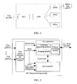
- FIG. 2 is a structure diagram of the OLT time processing module in the system for accurate time transfer of the present invention.
- the OLT time processing module is used to divide the current time into the PPnS and the TOD above second, wherein, the periodic PPnS generates the PPnS timestamp based on the local reference counter, and the corresponding data packets are generated from the PPnS timestamp and the TOD above second and broadcast to all the subordinate ONUs; and each of the subordinate ONU is ranged according to relevant protocol to obtain the ranging information, i.e. Round Trip Time (RTT), and the value of RTT is issued to each ONU in way of unicast.
- the OLT time processing module comprises: an OLT time source selecting and processing module, an OLT processor and an OLT controller.
- the OLT time source selecting and processing module is used to select the time source, wherein, the time source may provide wireless time service, and may also provide wired network time service, this sub-module outputs system clocks in uniform format, TOD above second, and pulse per n second (PPnS, n is a positive integer, generally 1, 2), TOD and PPnS form accurate time information, while the OLT time source selecting and processing module may also output the information of time status, comprising:
- TOD contains year, month, day, hour, minute, second corresponding to the current PPnS.
- the OLT time source selecting and processing module outputs a system clock as a reference clock of OLT device. It is not necessary for the system clock to synchronize with the time source, if the system clock synchronizes with the time source, however, it facilitates a more accurate output of time information of ONU.
- the OLT time source selecting and processing module outputs PPnS, and the PPnS is used to trigger the timestamp generating module to generate the PPnS timestamp corresponding to the PPnS, meanwhile the PPnS triggers the OLT controller as the triggering information transmitted by the PPnS timestamp and the TOD above second.
- the OLT processor is used to implement all the functions of OLT interface of passive optical network, and this module provides the ranging function of ONU for time transfer in the present invention to obtain the RTT value of the ranging information. It is a prerequisite of proper operation of the passive optical network to range each ONU accurately since the communication mode of time division multiplex is used in the uplink of the passive optical network.
- the OLT processor module further comprises: a timestamp generating module, a ranging module, and a protocol processing module.
- the ranging module is used to implement the ranging function according to the passive optical network protocol to obtain the ranging information RTT; the protocol processing module is used to implement the processing function of the passive optical network protocol; the timestamp generating module is used to generate the PPnS timestamp based on the local reference counter according to the PPnS transmitted by said time source selecting and processing module.
- the timestamp generating module contains a reference counter, and it is possible for the reference counter to take different forms in different PON systems, and the selecting principle is that the reference counter of OLT correlates with that of ONU, and generally, there is a relatively fixed difference value, which is related to the processing time of hardware and the round trip time (RTT) of physical link, the difference between the reference counter of OLT and that of ONU being approximately RTT/2.
- RTT round trip time
- the timestamp generating module generally uses a latch to generate a PPnS timestamp, and locks the value of the reference counter at the rising edge of a PPnS.
- a MPCP (Multiple Point Control Protocol) counter defined by IEEE802.3 is selected as the reference counter in the present invention.
- EPON When EPON sends MPCP data units, it will transmit the current value of the MPCP counter to ONU.
- ONU Upon reception of MPCP data units, ONU compares the received value of MPCP with that of the local counter, and updates the local MPCP counter if there is a difference.
- RTT/2 + ⁇ c between the MPCP counter of ONU and that of OLT, wherein ⁇ c is a difference caused by the asymmetry between uplink and downlink during the whole round trip processing, and the difference is commonly quite small and can be compensated partially by test and measurement.
- the reference counter to be implemented in the present invention is a combination of a super frame counter and an intra frame counter in Ident field in GPON Transmission Convergence (GTC) layer frame.
- GTC GPON Transmission Convergence
- the frame is sent at the frequency of 8K, and the frame header contains a super frame counter of 30 bit, which increases by one every time when one frame is sent.
- the intra frame counter counts with the start of GTC frame at frequency of 155.52MHz, whose period is 19,400.
- the ONU side reads the current value of a hyper frame from GTC frame, and the intra frame counter is accumulated by itself at a frequency of 155.52MHz starting from when the GTC frame header is received.
- the ranging mechanism of GPON focuses on the total round trip time for reaching OLT, therefore RTT contains the sending and processing time Ts of ONU, therefore the total delay between the reference counter of ONU and that of OLT is approximately (RTT-Ts)/2, and actual value may be compensated by test and measurement.
- the OLT controller is used to obtain the RTT value of each ONU from the OLT processor, and sends it in the way of unicast to each ONU by OLT controller. When RTT of a certain ONU has been changed, ONU will be re-informed.
- the OLT controller receives the PPnS triggering information of the time source selecting and processing module, and reads the PPnS timestamp generated by the timestamp generating module, and transmits it together with TOD and time status outputted by the time source selecting and processing module in way of broadcast to all the ONUs by OLT processor. Certainly, alternatively, they may be sent separately.
- the above described time-related information sent by the OLT controller may be communicated by PON data (service) plane, may also be communicated by PON management plane.
- the management plane is used in the specific implementation of the present invention, for example, the extended OAM frame is used specifically in EPON, and OMCC (ONU Manage and Control Channel) is used for transmission in the implementation of GPON.
- the OLT controller finely tunes timestamp and the RTT value of ONU according to the specific characteristics of system to make the time information outputted by ONU more accurate.
- FIG. 3 is an ONU time processing module in the system of accurate time transfer of the present invention, and the ONU time processing module is used to receive the time-related information (the PPnS timestamp, TOD and the information of time status etc.) and RTT value transmitted by OLT side, and output the corresponding accurate PPnS by estimation of period and prediction of the next second time.
- the time-related information the PPnS timestamp, TOD and the information of time status etc.
- RTT value transmitted by OLT side
- the ONU time processing module comprises an ONU processor, an ONU controller, a time synchronization processing module.
- the ONU processor is used to implement all the functions of ONU interface of passive optical network, and in the present invention, this module cooperates with the OLT time processing module to implement the ranging function, receives the time-related information sent by the OLT time processing module and provides a reference counter for the time synchronizing and processing module according to the protocol.
- the ONU controller is used to implement the following functions:
- the time synchronization processing module is used to receive the time corresponding to the next PPnS timestamp transmitted by said ONU controller, compare it with the reference counter in said ONU processor, and output the PPnS and the time information synchronously.
- time synchronization processing module There are two kinds of working status in time synchronization processing module, the following status and the self-generating status.
- the next PPnS time set by ONU controller and the reference counter outputted by ONU processor are compared, and the PPnS is outputted if they are equal, and at the same time the current TOD information is outputted.
- Self-generating status the PPnS and TOD information are self-outputted according to previous PPnS period and PPnS time.
- the working status is generated in the conditions of time source loss or anomalies.
- OLT time source it is possible for OLT time source to be lost or anomalous temporarily, and then ONU can still output the time information continuously, and maintain the accuracy of time information in a certain period of time.
- the present invention provides a method for time transfer in a passive optical network, comprising:
- the time information outputted by ONU time processing module in the present invention is of high accuracy.
- the time ambiguity introduced to the whole system correlates with the clock cycle of a reference counter, and the difference between the time of ONU and OLT is less than two counted clock cycles in a system with better compensation.
- the time information outputted by ONU time processing module in the present invention is of high accuracy.
- the time ambiguity introduced to the whole system correlates with the clock cycle of a reference counter, and the difference between the time of ONU and OLT is less than two counting clock cycles in a system with better compensation.
Description
- The present invention relates to the communication field of point-to-multipoint passive optical network (PON), and in particular, to one method and system for accurate time transfer in a passive optical network.
- Optical access technology provides large bandwidth and high reliability, and is a development direction of the access technology. PON is one of the major technologies of optical access, where A/BPON, EPON and GPON have been utilized in large scale.
- With the rapid development of data services, the mobility requirement of data access has emerged constantly, and the wired and wireless integration will meet the experiences of users better. With full-service access capability of data, voice and Time Division Multiplex (TDM), PON technology can meet wireless access demand in constant evolution. Especially in the access applications of micro-cells and home base stations, the convergency characteristic of PON makes the entire network clear in levels, convenient in construction, efficient in management.
- The mobile base stations of CDMA2000, TD-SCDMA and WiMAX etc. have strict requirement on time synchronization. Some value-added services provided by the mobile network also need strict time synchronization. At present, the wireless time service means, such as GPS etc., are mainly used on mobile base stations. In the construction of high quality wireless networks, time service using wired networks has great significance both in economy and in stability.
- In the process of IP-based network, the Precision Time Protocol (PTP) of network of IEEE1588 has been widely used in wireless base station. But PTP protocol works better in the condition of symmetric delay in the uplink and downlink of a network, and asymmetric nodes needs to be processed if it is an asymmetric network. PON is an asymmetric network for delay in the uplink and downlink, complicated flow processing, and excessive protocol workload and excessive network bandwidth occupancy occur when PTP protocol is dealt with in PON.
- Document XP068007550, FRANK J EFFENBERGER ET AL: "Time of day Distribution over E-PON" discloses a method for time transfer in E-PON (see Proposed Solution - Principle) where the OLT acquires an accurate real time receiving a sync message via IEEE 1588v2 and calculates the ToD when the first bit of a downstream MCPC frame that would carry a timestamp X would arrived at the ONU that has a latency zero based on the round trip time, RTT, measured by the OLT for the particular ONU and the ToD at which the first bit of a downstream MPCP frame that would carry the timestamp X would have departed from the OLT. The OLT afterwards sends to the particular ONU the timestamp X and the computed ToD, meaning, the ToD when the first bit of a downstream MCPC frame that would carry a timestamp X would arrived at the ONU that has a latency zero and the timestamp via MPCP.
- Document
US 2009/034672 A1 (CHO JAE-HUN [KR] ET AL) 5 February 2009 (2009-02-05) discloses a method and apparatus for time synchronization method using GPS information in a communication system synchronizing the time of slave nodes, which do not have a GPS receiver, by using GPS information of a node having a GPS receiver. The method includes the steps of extracting 1 PPS, TOD, 1PPS_en, and clocks using GPS signals by a grand master node having a GPS receiver, stabilizing the signals, generating a sync message for time synchronization, and transmitting the sync message to a slave node; receiving the sync message by the slave node and conducting a time synchronization operation using OFCC synchronization technology extracting 1 PPS, TOD, and 1PPS_en signals using the modified TOD information by the block and delivering to a stabilization block of the slave node for stabilization; and redelivering to the TS block to update TOD information and generate a sync message for TS of a second slave node. - In view of this, one of the main purposes of the present invention is to provide a method for time transfer in a passive optical network, which is used to solve the technical problems of complicated processing, excessive protocol workload, and excessive network bandwidth occupancy when using PTP to transfer time in a PON.
- To achieve the above purposes, the technical scheme of the present invention is implemented by:
- A method for time transfer in a passive optical network comprises:
- an optical line terminal (OLT) ranging optical network units (ONUs) and obtaining ranging information, then, triggered by a periodic pulse per n second (PPnS), generating a periodic PPnS timestamp and time of day (TOD) above second based on a local reference counter;
- the OLT sending said ranging information, the periodic PPnS timestamp and the TOD to the ONU;
- the ONUs predicting a time of the next second according to said periodic PPnS timestamp, the TOD and the ranging information, and outputting the PPnS corresponding to the time of the next second.
- Furthermore, the step of the ONUs predicting a time of the next second and outputting the corresponding PPnS comprises:
- the ONU estimating a PPnS period corresponding to the local reference counter, according to said periodic PPnS timestamp;
- the ONU estimating a time corresponding to the next PPnS timestamp according to said PPnS period, the ranging information and the currently received PPnS timestamp, and outputting a PPnS based on the local reference counter; wherein,
- the time corresponding to said next PPnS timestamp is that a sum of the currently received PPnS timestamp and said PPnS period subtracts half of a value of the ranging information.
- Furthermore, the above method further comprises: the OLT ranging the subordinate ONUs periodically, and if finding there is an ONU whose ranging information has been changed, transmitting new ranging information to the ONU whose ranging information has been changed.
- Furthermore, said ranging information is unicast to the ONU corresponding to the ranging information by a management plane or service plane, said periodic PPnS timestamp and the TOD are multicast to all the subordinate ONUs by the management plane or service plane.
- The present invention also provides an optical line terminal supporting time transfer in a passive optical network, said optical line terminal (OLT) comprising an OLT time processing module,
said OLT time processing module configured to generate a periodic pulse per n second (PPnS) timestamp and time of day (TOD) above second based on a local reference counter, triggered by a periodic PPnS; to range optical network units (ONUs) and generate ranging information; to transmit said PPnS timestamp, the TOD and the measured ranging information to the ONUs. - Furthermore, said OLT time processing module comprises:
- a time source selecting and processing module configured to select external time sources and covert the selected external time sources into an uniform system clock, a PPnS and the TOD;
- an OLT processor configured to range the ONUs and obtain the ranging information according to a passive optical network protocol; and to generate the PPnS timestamp based on the local reference counter according to the system clock and the PPnS inputted by said time source selecting and processing module;
- an OLT controller configured to form a data packet from the PPnS timestamp generated by the OLT processor, the TOD outputted by the time source selecting and processing module, and the ranging information measured by the OLT processor, and transmit the data packet to the ONUs through said OLT processor.
- Furthermore, said OLT processor comprises:
- a timestamp generating module configured to generate the PPnS timestamp based on the local reference counter, according to the PPnS transmitted by said time source selecting and processing module;
- a ranging module configured to implement a function of ranging the ONUs and obtain the ranging information, according to the passive optical network protocol;
- a protocol processing module configured to implement a processing function of the passive optical network protocol.
- Furthermore, said timestamp generating module comprises the reference counter,
- said timestamp generating module configured to generate the PPnS timestamp using a latch, and latching a value of said reference counter at a rising edge of the PPnS;
- said timestamp generating module also configured to use a multi-point control protocol (MPCP) counter as the reference counter in Ethernet Passive Optical Network (EPON); to use a combination of a super frame counter and an intra frame counter in Ident field in GTC frame of transmission convergence layer as the reference counter in Gigabit-Capable Passive Optical Network (GPON).
- Furthermore, said OLT time processing module is configured to transmit the ranging information in the way of unicast to the ONU corresponding to the ranging information by a management plane or service plane; and to transmit the PPnS timestamp and TOD in the way of broadcast to all the subordinate ONUs by the management plane or service plane;
said OLT time processing module is also configured to range the ONUs periodically and if finding there is an ONU whose ranging information has been changed, transmit new ranging information to the ONU whose ranging information has been changed. - The present invention also provides an optical network unit supporting time transfer in a passive optical network, said optical network unit (ONU) comprising an ONU time processing module,
said ONU time processing module configured to predict a time of the next second according to a periodic pulse per n second (PPnS) timestamp, time of day (TOD) and ranging information transmitted by an optical line terminal (OLT), and to output a PPnS corresponding to the time of the next second. - Furthermore, said ONU time processing module comprises:
- an ONU processor configured to receive the periodic PPnS timestamp, the TOD above second and the ranging information transmitted by said OLT, and to provide a reference counter for a time synchronizing module;
- an ONU controller configured to estimate a PPnS period based on a local reference counter, according to the periodic PPnS timestamp received by said ONU processor; to estimate a time corresponding to the next PPnS timestamp, according to said PPnS period, the ranging information and the currently received PPnS timestamp;
- a time synchronization processing module configured to receive the time corresponding to the next PPnS timestamp transmitted by said ONU controller, and compare the time with the reference counter in the ONU processor, and output the PPnS and the time information synchronously.
- Furthermore, working status of said time synchronization processing module is: following status or self-generating status;
in following status, said time synchronization processing module is configured to compare the next PPnS time set by said ONU controller with the reference counter outputted by the ONU processor, to output the PPnS if both are equal, and meanwhile output the current TOD information;
in self-generating status, said time synchronization processing module is configured to self-output the PPnS and TOD information according to a previous PPnS and PPnS time. - The present invention also provides a system for time transfer in a passive optical network, said system comprising the abovementioned optical line terminal and the abovementioned optical network unit.
- The invention combines the ranging characteristics of PON in time transfer, thereby having high accuracy in time transfer, and the low hardware cost for OLT and ONU, as well as the extremely small bandwidth occupancy due to the usage of a single copy of PON itself to broadcast the time information.
-
-
FIG. 1 is a system structure diagram of PON architecture; -
FIG. 2 is a system structure diagram of the OLT time processing module in the system for accurate time transfer of the present invention; -
FIG. 3 is a system structure diagram of the ONU time processing module in the system for accurate time transfer of the present invention. - The preferred examples of the present invention are illustrated below in conjunction with accompanying drawings, and it is appreciated that the preferred examples described herein are only intended for illustration and explanation of the present invention.
-
FIG. 1 is a system structure diagram of PON architecture, and the PON architecture generally consists of three parts of OLT (Optical Line Terminal), ODN (Optical Distribution Network), and ONU (Optical Network Unit). Generally, the distance from OLT to ONU is quite long, and it is up to 20km in EPON (Ethernet Passive Optical Network) while it is up to 60km in GPON (Gigabit-Capable PON). The time provider is commonly a mobile time server or a GPS. The part involved in the technical project of the present invention is in the dashed block, and the OLT time processing module in the present invention is located in the OLT, the ONU time processing module is located in the ONU. - The purpose of the present invention is to transmit the time information of OLT side accurately to ONU side. The time error is required no more than 3 microseconds in the system of CDMA2000 and no more than 1.5 microseconds in the system of TDS-CDMA, while by applying the technical scheme of the present invention, the error of time transfer from OLT to ONU can be implemented no more than 100 nanoseconds.
- The time information is divided into the pulse per n second (PPnS) and the time of day (TOD) above second in the system of PON, and is transmitted in conjunction with the characteristics of PON. The core idea of the present invention is: the time information is transferred effectively, economically and accurately, using the characteristics of PON point to multi-point and PON ranging.
-
FIG. 2 is a structure diagram of the OLT time processing module in the system for accurate time transfer of the present invention. The OLT time processing module is used to divide the current time into the PPnS and the TOD above second, wherein, the periodic PPnS generates the PPnS timestamp based on the local reference counter, and the corresponding data packets are generated from the PPnS timestamp and the TOD above second and broadcast to all the subordinate ONUs; and each of the subordinate ONU is ranged according to relevant protocol to obtain the ranging information, i.e. Round Trip Time (RTT), and the value of RTT is issued to each ONU in way of unicast. The OLT time processing module comprises: an OLT time source selecting and processing module, an OLT processor and an OLT controller. - The OLT time source selecting and processing module is used to select the time source, wherein, the time source may provide wireless time service, and may also provide wired network time service, this sub-module outputs system clocks in uniform format, TOD above second, and pulse per n second (PPnS, n is a positive integer, generally 1, 2), TOD and PPnS form accurate time information, while the OLT time source selecting and processing module may also output the information of time status, comprising:
- {the type, level, status of a clock source; locking instructions of the clock module (tracking, free running and locking)}
- TOD contains year, month, day, hour, minute, second corresponding to the current PPnS.
- The OLT time source selecting and processing module outputs a system clock as a reference clock of OLT device. It is not necessary for the system clock to synchronize with the time source, if the system clock synchronizes with the time source, however, it facilitates a more accurate output of time information of ONU.
- The OLT time source selecting and processing module outputs PPnS, and the PPnS is used to trigger the timestamp generating module to generate the PPnS timestamp corresponding to the PPnS, meanwhile the PPnS triggers the OLT controller as the triggering information transmitted by the PPnS timestamp and the TOD above second.
- The OLT processor is used to implement all the functions of OLT interface of passive optical network, and this module provides the ranging function of ONU for time transfer in the present invention to obtain the RTT value of the ranging information. It is a prerequisite of proper operation of the passive optical network to range each ONU accurately since the communication mode of time division multiplex is used in the uplink of the passive optical network.
- The OLT processor module further comprises: a timestamp generating module, a ranging module, and a protocol processing module.
- The ranging module is used to implement the ranging function according to the passive optical network protocol to obtain the ranging information RTT; the protocol processing module is used to implement the processing function of the passive optical network protocol; the timestamp generating module is used to generate the PPnS timestamp based on the local reference counter according to the PPnS transmitted by said time source selecting and processing module.
- The timestamp generating module contains a reference counter, and it is possible for the reference counter to take different forms in different PON systems, and the selecting principle is that the reference counter of OLT correlates with that of ONU, and generally, there is a relatively fixed difference value, which is related to the processing time of hardware and the round trip time (RTT) of physical link, the difference between the reference counter of OLT and that of ONU being approximately RTT/2.
- The timestamp generating module generally uses a latch to generate a PPnS timestamp, and locks the value of the reference counter at the rising edge of a PPnS.
- For the specific implementation of the reference counter in EPON, a MPCP (Multiple Point Control Protocol) counter defined by IEEE802.3 is selected as the reference counter in the present invention. When EPON sends MPCP data units, it will transmit the current value of the MPCP counter to ONU. Upon reception of MPCP data units, ONU compares the received value of MPCP with that of the local counter, and updates the local MPCP counter if there is a difference. There is a difference of RTT/2 +Δ c between the MPCP counter of ONU and that of OLT, whereinΔ c is a difference caused by the asymmetry between uplink and downlink during the whole round trip processing, and the difference is commonly quite small and can be compensated partially by test and measurement.
- For the specific implementation of the reference counter in GPON, the reference counter to be implemented in the present invention is a combination of a super frame counter and an intra frame counter in Ident field in GPON Transmission Convergence (GTC) layer frame. In a downlink frame of GPON, the frame is sent at the frequency of 8K, and the frame header contains a super frame counter of 30 bit, which increases by one every time when one frame is sent. The intra frame counter counts with the start of GTC frame at frequency of 155.52MHz, whose period is 19,400. The ONU side reads the current value of a hyper frame from GTC frame, and the intra frame counter is accumulated by itself at a frequency of 155.52MHz starting from when the GTC frame header is received. Differing from the ranging mechanism of EPON, the ranging mechanism of GPON focuses on the total round trip time for reaching OLT, therefore RTT contains the sending and processing time Ts of ONU, therefore the total delay between the reference counter of ONU and that of OLT is approximately (RTT-Ts)/2, and actual value may be compensated by test and measurement.
- The OLT controller is used to obtain the RTT value of each ONU from the OLT processor, and sends it in the way of unicast to each ONU by OLT controller. When RTT of a certain ONU has been changed, ONU will be re-informed.
- The OLT controller receives the PPnS triggering information of the time source selecting and processing module, and reads the PPnS timestamp generated by the timestamp generating module, and transmits it together with TOD and time status outputted by the time source selecting and processing module in way of broadcast to all the ONUs by OLT processor. Certainly, alternatively, they may be sent separately.
- The above described time-related information sent by the OLT controller may be communicated by PON data (service) plane, may also be communicated by PON management plane. The management plane is used in the specific implementation of the present invention, for example, the extended OAM frame is used specifically in EPON, and OMCC (ONU Manage and Control Channel) is used for transmission in the implementation of GPON. The OLT controller finely tunes timestamp and the RTT value of ONU according to the specific characteristics of system to make the time information outputted by ONU more accurate.
-
FIG. 3 is an ONU time processing module in the system of accurate time transfer of the present invention, and the ONU time processing module is used to receive the time-related information (the PPnS timestamp, TOD and the information of time status etc.) and RTT value transmitted by OLT side, and output the corresponding accurate PPnS by estimation of period and prediction of the next second time. - The ONU time processing module comprises an ONU processor, an ONU controller, a time synchronization processing module.
- The ONU processor is used to implement all the functions of ONU interface of passive optical network, and in the present invention, this module cooperates with the OLT time processing module to implement the ranging function, receives the time-related information sent by the OLT time processing module and provides a reference counter for the time synchronizing and processing module according to the protocol.
- The ONU controller is used to implement the following functions:
- 1, Receive the PPnS timestamp, the ranging information RTT, TOD and the information of time status obtained from OLT side by the ONU processor;
- 2, Estimate the PPnS period
T based on the local reference counter according to the PPnS timestamp sent periodically by OLT side; the estimation method is: performing subtract on each two adjacent PPnS timestamps to obtain the current period of a counter, and making average for the historical periods to obtainT . - 3, Estimate time corresponding to the next PPnS timestamp according to the PPnS period
T estimated by the ONU, the ranging information RTT of the ONU received from OLT side and the currently received PPnS timestamp (the currently received PPnS timestamp+T- RTT/2), and set the time value into the time synchronization processing module; - 4, Obtain the TOD value of the next second by increasing TOD corresponding to the current PPnS timestamp with 1 second, and set the TOD value of the next second into the time synchronization processing module.
- 5, Set the working status of the time synchronization processing module according to the received information of time status.
- The time synchronization processing module is used to receive the time corresponding to the next PPnS timestamp transmitted by said ONU controller, compare it with the reference counter in said ONU processor, and output the PPnS and the time information synchronously. There are two kinds of working status in time synchronization processing module, the following status and the self-generating status.
- Following status: the next PPnS time set by ONU controller and the reference counter outputted by ONU processor are compared, and the PPnS is outputted if they are equal, and at the same time the current TOD information is outputted.
- Self-generating status: the PPnS and TOD information are self-outputted according to previous PPnS period and PPnS time. The working status is generated in the conditions of time source loss or anomalies. In the status of self-generating, it is possible for OLT time source to be lost or anomalous temporarily, and then ONU can still output the time information continuously, and maintain the accuracy of time information in a certain period of time.
- The present invention provides a method for time transfer in a passive optical network, comprising:
- an optical line terminal (OLT) ranging an optical network unit (ONU) to obtain the ranging information, then, triggered by the periodic PPnS, generating the periodic PPnS timestamp and the TOD above second based on the local reference counter;
- OLT transferring said ranging information, periodic PPnS timestamp and TOD to ONU;
- ONU predicting the time in the next second according to said periodic PPnS timestamp, TOD and the ranging information, and outputting the PPnS corresponding to the next second time.
- The time information outputted by ONU time processing module in the present invention is of high accuracy. The time ambiguity introduced to the whole system correlates with the clock cycle of a reference counter, and the difference between the time of ONU and OLT is less than two counted clock cycles in a system with better compensation.
- Choice and implementation of a reference counter in EPON/GPON are listed in the preferred examples, but it cannot constitute a limitation of the present invention, neither of EPON and GPON. The above described are merely preferred embodiments of the present invention, and not intended to limit the present invention, and for the person skilled in the art, various modifications and changes may be made to the present invention.
- The time information outputted by ONU time processing module in the present invention is of high accuracy. The time ambiguity introduced to the whole system correlates with the clock cycle of a reference counter, and the difference between the time of ONU and OLT is less than two counting clock cycles in a system with better compensation.
Claims (13)
- A method for time transfer in a passive optical network, comprising:an optical line terminal (OLT) ranging optical network units (ONUs) and obtaining ranging information characterized in that, then, triggered by a periodic pulse per n second (PPnS), generating a periodic PPnS timestamp and time of day (TOD) above second based on a local reference counter;the OLT sending said ranging information, the periodic PPnS timestamp and the TOD to the ONU;the ONU predicting a time of the next second according to said periodic PPnS timestamp, the TOD and the ranging information, and outputting the PPnS corresponding to the time of the next second.
- The method according to claim 1, wherein, the step of predicting a time of the next second and outputting the PPnS corresponding to the time of the next second comprises:the ONU estimating a PPnS period corresponding to the local reference counter, according to said periodic PPnS timestamp;the ONU estimating a time corresponding to the next PPnS timestamp according to said PPnS period, the ranging information and the currently received PPnS timestamp, and outputting a PPnS based on the local reference counter; wherein,the time corresponding to said next PPnS timestamp is that a sum of the currently received PPnS timestamp and said PPnS period subtracts half of a value of the ranging information.
- The method according to claim 1 or 2, further comprising: the OLT ranging the subordinate ONUs periodically, and if finding there is an ONU whose ranging information has been changed, transmitting new ranging information to the ONU whose ranging information has been changed.
- The method according to claim 3, wherein, said ranging information is unicast to the ONU corresponding to the ranging information by a management plane or service plane, said periodic PPnS timestamp and the TOD are multicast to all the subordinate ONUs by the management plane or service plane.
- An optical line terminal supporting time transfer in a passive optical network, said optical line terminal (OLT) comprising an OLT time processing module characterized by,
said OLT time processing module configured to generate a periodic pulse per n second (PPnS) timestamp and time of day (TOD) above second based on a local reference counter, triggered by a periodic PPnS; to range optical network units (ONUs) and generate ranging information; to transmit said PPnS timestamp, the TOD and the measured ranging information to the ONUs. - The optical line terminal according to claim 5, wherein, said OLT time processing module comprises:a time source selecting and processing module configured to select external time sources and covert the selected external time sources into an uniform system clock, a PPnS and the TOD;an OLT processor configured to range the ONUs and obtain the ranging information according to a passive optical network protocol; and to generate the PPnS timestamp based on the local reference counter according to the system clock and the PPnS inputted by said time source selecting and processing module;an OLT controller configured to form a data packet from the PPnS timestamp generated by the OLT processor, the TOD outputted by the time source selecting and processing module, and the ranging information measured by the OLT processor, and transmit the data packet to the ONUs through said OLT processor.
- The optical line terminal according to claim 6, wherein, said OLT processor comprises:a timestamp generating module configured to generate the PPnS timestamp based on the local reference counter, according to the PPnS transmitted by said time source selecting and processing module;a ranging module configured to implement a function of ranging the ONUs and obtain the ranging information, according to the passive optical network protocol;a protocol processing module configured to implement a processing function of the passive optical network protocol.
- The optical line terminal according to claim 7, wherein, said timestamp generating module comprises the reference counter,
said timestamp generating module configured to generate the PPnS timestamp using a latch, and latching a value of said reference counter at a rising edge of the PPnS;
said timestamp generating module also configured to use a multi-point control protocol (MPCP) counter as the reference counter in Ethernet Passive Optical Network (EPON); to use a combination of a super frame counter and an intra frame counter in Ident field in GTC frame of transmission convergence layer as the reference counter in Gigabit-Capable Passive Optical Network (GPON). - The optical line terminal according to claim 5, wherein,
said OLT time processing module is configured to transmit the ranging information in the way of unicast to the ONU corresponding to the ranging information by a management plane or service plane; and to transmit the PPnS timestamp and TOD in the way of broadcast to all the subordinate ONUs by the management plane or service plane;
said OLT time processing module is also configured to range the ONUs periodically and if finding there is an ONU whose ranging information has been changed, transmit new ranging information to the ONU whose ranging information has been changed. - An optical network unit supporting time transfer in a passive optical network, said optical network unit (ONU) comprising an ONU time processing module characterized by,
said ONU time processing module configured to predict a time of the next second according to a periodic pulse per n second (PPnS) timestamp, time of day (TOD) and ranging information transmitted by an optical line terminal (OLT), and to output a PPnS corresponding to the time of the next second. - The optical network unit according to claim 10, wherein, said ONU time processing module comprises:an ONU processor configured to receive the periodic PPnS timestamp, the TOD above second and the ranging information transmitted by said OLT, and to provide a reference counter for a time synchronizing module;an ONU controller configured to estimate a PPnS period based on a local reference counter, according to the periodic PPnS timestamp received by said ONU processor; to estimate a time corresponding to the next PPnS timestamp, according to said PPnS period, the ranging information and the currently received PPnS timestamp;a time synchronization processing module configured to receive the time corresponding to the next PPnS timestamp transmitted by said ONU controller, and compare the time with the reference counter in the ONU processor, and output the PPnS and the time information synchronously.
- The optical network unit according to claim 11, wherein, working status of said time synchronization processing module is: following status or self-generating status;
in following status, said time synchronization processing module is configured to compare the next PPnS time set by said ONU controller with the reference counter outputted by the ONU processor, to output the PPnS if both are equal, and meanwhile output the current TOD information;
in self-generating status, said time synchronization processing module is configured to self-output the PPnS and TOD information according to a previous PPnS and PPnS time. - A system for time transfer in a passive optical network, said system comprising said optical line terminal (OLT) of any of claims 5-9, and said optical network unit (ONU) of any of claims 10-12.
Applications Claiming Priority (2)
| Application Number | Priority Date | Filing Date | Title |
|---|---|---|---|
| CN200910080379.0A CN101841736B (en) | 2009-03-20 | 2009-03-20 | Method and system for transferring time in passive optical network (PON) |
| PCT/CN2009/074351 WO2010105475A1 (en) | 2009-03-20 | 2009-09-30 | Method and system for transmitting time in passive optical network |
Publications (3)
| Publication Number | Publication Date |
|---|---|
| EP2410672A1 EP2410672A1 (en) | 2012-01-25 |
| EP2410672A4 EP2410672A4 (en) | 2014-03-12 |
| EP2410672B1 true EP2410672B1 (en) | 2014-09-17 |
Family
ID=42739157
Family Applications (1)
| Application Number | Title | Priority Date | Filing Date |
|---|---|---|---|
| EP09841758.7A Active EP2410672B1 (en) | 2009-03-20 | 2009-09-30 | Method and system for transmitting time in passive optical network |
Country Status (5)
| Country | Link |
|---|---|
| US (1) | US8725002B2 (en) |
| EP (1) | EP2410672B1 (en) |
| CN (1) | CN101841736B (en) |
| ES (1) | ES2524600T3 (en) |
| WO (1) | WO2010105475A1 (en) |
Cited By (1)
| Publication number | Priority date | Publication date | Assignee | Title |
|---|---|---|---|---|
| KR101697059B1 (en) * | 2015-09-30 | 2017-01-17 | 주식회사 다산네트웍솔루션즈 | Time synchronization method for Telecommunication Network |
Families Citing this family (25)
| Publication number | Priority date | Publication date | Assignee | Title |
|---|---|---|---|---|
| JP5576747B2 (en) * | 2010-09-06 | 2014-08-20 | 株式会社日立製作所 | Communication system and time synchronization method |
| US8630546B2 (en) * | 2010-11-01 | 2014-01-14 | Calix, Inc. | Network interface device synchronization |
| CN102130764A (en) * | 2010-12-01 | 2011-07-20 | 华为技术有限公司 | Method, system and device for sending time synchronization information |
| CN102006136A (en) * | 2010-12-17 | 2011-04-06 | 武汉邮电科学研究院 | Method and device for improving clock synchronization precision in EPON |
| CN102098121B (en) * | 2010-12-29 | 2014-09-03 | 华为技术有限公司 | Method and device for monitoring time synchronization |
| US8867404B2 (en) * | 2012-02-03 | 2014-10-21 | Futurewei Technologies, Inc. | Node level vectoring synchronization |
| US8681772B2 (en) | 2012-05-11 | 2014-03-25 | Vitesse Semiconductor Corporation | Timing synchronization for networks with radio links |
| WO2013191608A1 (en) * | 2012-06-18 | 2013-12-27 | Telefonaktiebolaget L M Ericsson (Publ) | Time domains in a PON |
| CN103634709B (en) * | 2012-08-28 | 2018-01-12 | 上海诺基亚贝尔股份有限公司 | Method for supporting optical network unit to be migrated between multiple EPONs |
| CN104579529B (en) * | 2013-10-22 | 2018-08-17 | 中国移动通信集团公司 | A kind of method and apparatus of Synchronization Status Message |
| CN103532792B (en) * | 2013-10-25 | 2017-11-17 | 中磊电子(苏州)有限公司 | network bandwidth measuring method |
| CN105471603B (en) | 2014-08-19 | 2020-12-11 | 中兴通讯股份有限公司 | Method, device and system for remotely configuring PTP (precision time protocol) service of optical network unit |
| JP6381384B2 (en) * | 2014-09-18 | 2018-08-29 | Kddi株式会社 | PON system, ONU, OLT, and transmission method |
| JP6381392B2 (en) * | 2014-09-30 | 2018-08-29 | Kddi株式会社 | PON system, OLT, ONU, and transmission method |
| CN105703893A (en) * | 2014-11-25 | 2016-06-22 | 中兴通讯股份有限公司 | Clock source attribute synchronization method, clock source attribute synchronization device and clock source attribute synchronization system |
| US20170302433A1 (en) * | 2015-05-15 | 2017-10-19 | Alcatel-Lucent Usa Inc. | Method And Apparatus For Time Transport In A Communication Network |
| CN105471539B (en) * | 2015-06-11 | 2019-03-01 | 南京智汇电力技术有限公司 | A method of synchronous data collection is realized based on passive optical network |
| CN105472483B (en) * | 2015-06-12 | 2019-03-01 | 南京智汇电力技术有限公司 | A kind of passive optical network data acquisition method based on double sampling |
| KR102388504B1 (en) * | 2015-12-18 | 2022-04-21 | 주식회사 쏠리드 | Method and apparatus for compensating fiber opticdelay |
| CN109217959B (en) * | 2017-07-04 | 2021-04-20 | 百度在线网络技术(北京)有限公司 | Method, device and server for synchronizing time |
| JP2019140657A (en) * | 2018-02-15 | 2019-08-22 | 沖電気工業株式会社 | Optical line terminal, optical network unit, optical communication system, station side program, subscriber side program, and time synchronization program |
| CN108599843B (en) * | 2018-05-07 | 2021-02-12 | 上海市共进通信技术有限公司 | Function detection control method for supporting output of 1PPS and TOD signals in SFP ONT optical module and host |
| US10890914B2 (en) * | 2018-08-24 | 2021-01-12 | Baidu Usa Llc | Trigger logic to trigger sensors of an autonomous driving vehicle for capturing data |
| CN109164354A (en) * | 2018-09-29 | 2019-01-08 | 云南电网有限责任公司电力科学研究院 | A kind of method of locating terminal of the distribution wide area self-healing system based on passive optical network |
| CN112865860B (en) * | 2021-01-05 | 2022-04-26 | 深圳市双翼科技股份有限公司 | Calibration method and device for trillion passive optical network BOB equipment |
Family Cites Families (8)
| Publication number | Priority date | Publication date | Assignee | Title |
|---|---|---|---|---|
| DE502005007060D1 (en) * | 2004-12-16 | 2009-05-20 | Siemens Ag | SYNCHRONIZATION MODULE |
| JP4168059B2 (en) * | 2006-04-10 | 2008-10-22 | 株式会社日立コミュニケーションテクノロジー | PON system and station side device |
| JP2007295151A (en) * | 2006-04-24 | 2007-11-08 | Sumitomo Electric Ind Ltd | Pon system and station side apparatus and terminal used for the same |
| CN101192885A (en) | 2006-11-27 | 2008-06-04 | 华为技术有限公司 | A distance measuring method and system for passive optical network |
| KR100876776B1 (en) * | 2007-04-17 | 2009-01-09 | 삼성전자주식회사 | Method and apparatus for synchronizing time in a communication system using gps information |
| JP5122890B2 (en) * | 2007-09-06 | 2013-01-16 | 株式会社日立製作所 | Communication system and apparatus |
| JP2009290626A (en) * | 2008-05-30 | 2009-12-10 | Kddi Corp | Optical transmission system and time reference pulse synchronizing method |
| US8942561B2 (en) * | 2008-10-21 | 2015-01-27 | Broadcom Corporation | Synchronization transport over passive optical networks |
-
2009
- 2009-03-20 CN CN200910080379.0A patent/CN101841736B/en not_active Expired - Fee Related
- 2009-09-30 WO PCT/CN2009/074351 patent/WO2010105475A1/en active Application Filing
- 2009-09-30 US US13/257,466 patent/US8725002B2/en active Active - Reinstated
- 2009-09-30 ES ES09841758.7T patent/ES2524600T3/en active Active
- 2009-09-30 EP EP09841758.7A patent/EP2410672B1/en active Active
Cited By (2)
| Publication number | Priority date | Publication date | Assignee | Title |
|---|---|---|---|---|
| KR101697059B1 (en) * | 2015-09-30 | 2017-01-17 | 주식회사 다산네트웍솔루션즈 | Time synchronization method for Telecommunication Network |
| WO2017057794A1 (en) * | 2015-09-30 | 2017-04-06 | 주식회사 다산네트웍솔루션즈 | Method for time synchronization of communication network |
Also Published As
| Publication number | Publication date |
|---|---|
| CN101841736A (en) | 2010-09-22 |
| US20120008953A1 (en) | 2012-01-12 |
| WO2010105475A1 (en) | 2010-09-23 |
| EP2410672A4 (en) | 2014-03-12 |
| US8725002B2 (en) | 2014-05-13 |
| ES2524600T3 (en) | 2014-12-10 |
| CN101841736B (en) | 2014-03-12 |
| EP2410672A1 (en) | 2012-01-25 |
Similar Documents
| Publication | Publication Date | Title |
|---|---|---|
| EP2410672B1 (en) | Method and system for transmitting time in passive optical network | |
| US8582606B2 (en) | Network system with synchronization and method of operation thereof | |
| US8126333B2 (en) | Optical transmission system and synchronization method using time reference pulse | |
| US9014282B2 (en) | Precision timing in a data over cable service interface specification (DOCSIS) system | |
| Lv et al. | An enhanced IEEE 1588 time synchronization for asymmetric communication link in packet transport network | |
| EP2518951B1 (en) | Method, equipment and system for time synchronization of passive optical network | |
| US7903681B2 (en) | Method for distributing a common time reference within a distributed architecture | |
| EP2580883B1 (en) | Node and system for a synchronous network | |
| WO2010017762A1 (en) | Time synchronization method and device for passive optical network and passive optical network | |
| JP6278643B2 (en) | Slave station device, master station device, control device, communication system, and time synchronization method | |
| CN103259640A (en) | Method and device for synchronizing time | |
| US20220038252A1 (en) | Methods, Apparatus and Computer-Readable Media for Synchronization Over an Optical Network | |
| KR101285277B1 (en) | Method and system for time synchronization in a passive optical network | |
| Luo et al. | Time synchronization over ethernet passive optical networks | |
| CN111446776A (en) | Wide area protection control system suitable for urban distribution network | |
| JP2017073752A (en) | Pon system transmission method | |
| KR20160024782A (en) | network synchronization apparatus and method on passive optical access network | |
| JP2011040870A (en) | Optical transmission system, and synchronization method using time reference pulse | |
| JP2004336354A (en) | Method to use uplink band in optical burst transmission/reception network | |
| US20170302433A1 (en) | Method And Apparatus For Time Transport In A Communication Network | |
| CN211880179U (en) | Wide area protection control system suitable for urban distribution network | |
| Horiuchi et al. | Precise time distribution using ethernet passive optical network | |
| Yazawa et al. | High accurately synchronized λ-tunable WDM/TDM-PON using timestamps based time and frequency synchronization for mobile backhaul | |
| Wang et al. | Implementation of EPON systems supporting accurate time synchronization | |
| Yang et al. | New algorithm for IEEE 1588 time synchronization under the presence of significant delay variation |
Legal Events
| Date | Code | Title | Description |
|---|---|---|---|
| PUAI | Public reference made under article 153(3) epc to a published international application that has entered the european phase |
Free format text: ORIGINAL CODE: 0009012 |
|
| 17P | Request for examination filed |
Effective date: 20111019 |
|
| AK | Designated contracting states |
Kind code of ref document: A1 Designated state(s): AT BE BG CH CY CZ DE DK EE ES FI FR GB GR HR HU IE IS IT LI LT LU LV MC MK MT NL NO PL PT RO SE SI SK SM TR |
|
| DAX | Request for extension of the european patent (deleted) | ||
| A4 | Supplementary search report drawn up and despatched |
Effective date: 20140206 |
|
| RIC1 | Information provided on ipc code assigned before grant |
Ipc: H04J 3/06 20060101AFI20140131BHEP Ipc: H04Q 11/00 20060101ALI20140131BHEP |
|
| REG | Reference to a national code |
Ref country code: DE Ref legal event code: R079 Ref document number: 602009026776 Country of ref document: DE Free format text: PREVIOUS MAIN CLASS: H04B0010000000 Ipc: H04J0003060000 |
|
| RIC1 | Information provided on ipc code assigned before grant |
Ipc: H04Q 11/00 20060101ALI20140331BHEP Ipc: H04J 3/06 20060101AFI20140331BHEP |
|
| GRAP | Despatch of communication of intention to grant a patent |
Free format text: ORIGINAL CODE: EPIDOSNIGR1 |
|
| INTG | Intention to grant announced |
Effective date: 20140509 |
|
| GRAS | Grant fee paid |
Free format text: ORIGINAL CODE: EPIDOSNIGR3 |
|
| GRAA | (expected) grant |
Free format text: ORIGINAL CODE: 0009210 |
|
| AK | Designated contracting states |
Kind code of ref document: B1 Designated state(s): AT BE BG CH CY CZ DE DK EE ES FI FR GB GR HR HU IE IS IT LI LT LU LV MC MK MT NL NO PL PT RO SE SI SK SM TR |
|
| REG | Reference to a national code |
Ref country code: GB Ref legal event code: FG4D |
|
| REG | Reference to a national code |
Ref country code: CH Ref legal event code: EP |
|
| REG | Reference to a national code |
Ref country code: IE Ref legal event code: FG4D |
|
| REG | Reference to a national code |
Ref country code: AT Ref legal event code: REF Ref document number: 688096 Country of ref document: AT Kind code of ref document: T Effective date: 20141015 |
|
| REG | Reference to a national code |
Ref country code: DE Ref legal event code: R096 Ref document number: 602009026776 Country of ref document: DE Effective date: 20141030 |
|
| REG | Reference to a national code |
Ref country code: ES Ref legal event code: FG2A Ref document number: 2524600 Country of ref document: ES Kind code of ref document: T3 Effective date: 20141210 |
|
| PG25 | Lapsed in a contracting state [announced via postgrant information from national office to epo] |
Ref country code: GR Free format text: LAPSE BECAUSE OF FAILURE TO SUBMIT A TRANSLATION OF THE DESCRIPTION OR TO PAY THE FEE WITHIN THE PRESCRIBED TIME-LIMIT Effective date: 20141218 Ref country code: FI Free format text: LAPSE BECAUSE OF FAILURE TO SUBMIT A TRANSLATION OF THE DESCRIPTION OR TO PAY THE FEE WITHIN THE PRESCRIBED TIME-LIMIT Effective date: 20140917 Ref country code: NO Free format text: LAPSE BECAUSE OF FAILURE TO SUBMIT A TRANSLATION OF THE DESCRIPTION OR TO PAY THE FEE WITHIN THE PRESCRIBED TIME-LIMIT Effective date: 20141217 Ref country code: SE Free format text: LAPSE BECAUSE OF FAILURE TO SUBMIT A TRANSLATION OF THE DESCRIPTION OR TO PAY THE FEE WITHIN THE PRESCRIBED TIME-LIMIT Effective date: 20140917 Ref country code: LT Free format text: LAPSE BECAUSE OF FAILURE TO SUBMIT A TRANSLATION OF THE DESCRIPTION OR TO PAY THE FEE WITHIN THE PRESCRIBED TIME-LIMIT Effective date: 20140917 |
|
| REG | Reference to a national code |
Ref country code: NL Ref legal event code: VDEP Effective date: 20140917 |
|
| REG | Reference to a national code |
Ref country code: LT Ref legal event code: MG4D |
|
| PG25 | Lapsed in a contracting state [announced via postgrant information from national office to epo] |
Ref country code: HR Free format text: LAPSE BECAUSE OF FAILURE TO SUBMIT A TRANSLATION OF THE DESCRIPTION OR TO PAY THE FEE WITHIN THE PRESCRIBED TIME-LIMIT Effective date: 20140917 Ref country code: CY Free format text: LAPSE BECAUSE OF FAILURE TO SUBMIT A TRANSLATION OF THE DESCRIPTION OR TO PAY THE FEE WITHIN THE PRESCRIBED TIME-LIMIT Effective date: 20140917 Ref country code: LV Free format text: LAPSE BECAUSE OF FAILURE TO SUBMIT A TRANSLATION OF THE DESCRIPTION OR TO PAY THE FEE WITHIN THE PRESCRIBED TIME-LIMIT Effective date: 20140917 |
|
| REG | Reference to a national code |
Ref country code: AT Ref legal event code: MK05 Ref document number: 688096 Country of ref document: AT Kind code of ref document: T Effective date: 20140917 |
|
| PG25 | Lapsed in a contracting state [announced via postgrant information from national office to epo] |
Ref country code: NL Free format text: LAPSE BECAUSE OF FAILURE TO SUBMIT A TRANSLATION OF THE DESCRIPTION OR TO PAY THE FEE WITHIN THE PRESCRIBED TIME-LIMIT Effective date: 20140917 |
|
| PG25 | Lapsed in a contracting state [announced via postgrant information from national office to epo] |
Ref country code: PT Free format text: LAPSE BECAUSE OF FAILURE TO SUBMIT A TRANSLATION OF THE DESCRIPTION OR TO PAY THE FEE WITHIN THE PRESCRIBED TIME-LIMIT Effective date: 20150119 Ref country code: IS Free format text: LAPSE BECAUSE OF FAILURE TO SUBMIT A TRANSLATION OF THE DESCRIPTION OR TO PAY THE FEE WITHIN THE PRESCRIBED TIME-LIMIT Effective date: 20150117 Ref country code: SK Free format text: LAPSE BECAUSE OF FAILURE TO SUBMIT A TRANSLATION OF THE DESCRIPTION OR TO PAY THE FEE WITHIN THE PRESCRIBED TIME-LIMIT Effective date: 20140917 Ref country code: EE Free format text: LAPSE BECAUSE OF FAILURE TO SUBMIT A TRANSLATION OF THE DESCRIPTION OR TO PAY THE FEE WITHIN THE PRESCRIBED TIME-LIMIT Effective date: 20140917 Ref country code: CZ Free format text: LAPSE BECAUSE OF FAILURE TO SUBMIT A TRANSLATION OF THE DESCRIPTION OR TO PAY THE FEE WITHIN THE PRESCRIBED TIME-LIMIT Effective date: 20140917 Ref country code: RO Free format text: LAPSE BECAUSE OF FAILURE TO SUBMIT A TRANSLATION OF THE DESCRIPTION OR TO PAY THE FEE WITHIN THE PRESCRIBED TIME-LIMIT Effective date: 20140917 |
|
| REG | Reference to a national code |
Ref country code: CH Ref legal event code: PL |
|
| PG25 | Lapsed in a contracting state [announced via postgrant information from national office to epo] |
Ref country code: PL Free format text: LAPSE BECAUSE OF FAILURE TO SUBMIT A TRANSLATION OF THE DESCRIPTION OR TO PAY THE FEE WITHIN THE PRESCRIBED TIME-LIMIT Effective date: 20140917 Ref country code: AT Free format text: LAPSE BECAUSE OF FAILURE TO SUBMIT A TRANSLATION OF THE DESCRIPTION OR TO PAY THE FEE WITHIN THE PRESCRIBED TIME-LIMIT Effective date: 20140917 |
|
| REG | Reference to a national code |
Ref country code: DE Ref legal event code: R097 Ref document number: 602009026776 Country of ref document: DE |
|
| PG25 | Lapsed in a contracting state [announced via postgrant information from national office to epo] |
Ref country code: BE Free format text: LAPSE BECAUSE OF NON-PAYMENT OF DUE FEES Effective date: 20140930 Ref country code: MC Free format text: LAPSE BECAUSE OF FAILURE TO SUBMIT A TRANSLATION OF THE DESCRIPTION OR TO PAY THE FEE WITHIN THE PRESCRIBED TIME-LIMIT Effective date: 20140917 |
|
| REG | Reference to a national code |
Ref country code: IE Ref legal event code: MM4A |
|
| PLBE | No opposition filed within time limit |
Free format text: ORIGINAL CODE: 0009261 |
|
| STAA | Information on the status of an ep patent application or granted ep patent |
Free format text: STATUS: NO OPPOSITION FILED WITHIN TIME LIMIT |
|
| PG25 | Lapsed in a contracting state [announced via postgrant information from national office to epo] |
Ref country code: LI Free format text: LAPSE BECAUSE OF NON-PAYMENT OF DUE FEES Effective date: 20140930 Ref country code: CH Free format text: LAPSE BECAUSE OF NON-PAYMENT OF DUE FEES Effective date: 20140930 Ref country code: DK Free format text: LAPSE BECAUSE OF FAILURE TO SUBMIT A TRANSLATION OF THE DESCRIPTION OR TO PAY THE FEE WITHIN THE PRESCRIBED TIME-LIMIT Effective date: 20140917 |
|
| 26N | No opposition filed |
Effective date: 20150618 |
|
| PG25 | Lapsed in a contracting state [announced via postgrant information from national office to epo] |
Ref country code: IT Free format text: LAPSE BECAUSE OF FAILURE TO SUBMIT A TRANSLATION OF THE DESCRIPTION OR TO PAY THE FEE WITHIN THE PRESCRIBED TIME-LIMIT Effective date: 20140917 Ref country code: IE Free format text: LAPSE BECAUSE OF NON-PAYMENT OF DUE FEES Effective date: 20140930 |
|
| PG25 | Lapsed in a contracting state [announced via postgrant information from national office to epo] |
Ref country code: SI Free format text: LAPSE BECAUSE OF FAILURE TO SUBMIT A TRANSLATION OF THE DESCRIPTION OR TO PAY THE FEE WITHIN THE PRESCRIBED TIME-LIMIT Effective date: 20140917 |
|
| PG25 | Lapsed in a contracting state [announced via postgrant information from national office to epo] |
Ref country code: SM Free format text: LAPSE BECAUSE OF FAILURE TO SUBMIT A TRANSLATION OF THE DESCRIPTION OR TO PAY THE FEE WITHIN THE PRESCRIBED TIME-LIMIT Effective date: 20140917 |
|
| PG25 | Lapsed in a contracting state [announced via postgrant information from national office to epo] |
Ref country code: MT Free format text: LAPSE BECAUSE OF FAILURE TO SUBMIT A TRANSLATION OF THE DESCRIPTION OR TO PAY THE FEE WITHIN THE PRESCRIBED TIME-LIMIT Effective date: 20140917 Ref country code: BG Free format text: LAPSE BECAUSE OF FAILURE TO SUBMIT A TRANSLATION OF THE DESCRIPTION OR TO PAY THE FEE WITHIN THE PRESCRIBED TIME-LIMIT Effective date: 20140917 |
|
| PG25 | Lapsed in a contracting state [announced via postgrant information from national office to epo] |
Ref country code: LU Free format text: LAPSE BECAUSE OF NON-PAYMENT OF DUE FEES Effective date: 20140930 Ref country code: HU Free format text: LAPSE BECAUSE OF FAILURE TO SUBMIT A TRANSLATION OF THE DESCRIPTION OR TO PAY THE FEE WITHIN THE PRESCRIBED TIME-LIMIT; INVALID AB INITIO Effective date: 20090930 Ref country code: TR Free format text: LAPSE BECAUSE OF FAILURE TO SUBMIT A TRANSLATION OF THE DESCRIPTION OR TO PAY THE FEE WITHIN THE PRESCRIBED TIME-LIMIT Effective date: 20140917 |
|
| REG | Reference to a national code |
Ref country code: FR Ref legal event code: PLFP Year of fee payment: 8 |
|
| REG | Reference to a national code |
Ref country code: FR Ref legal event code: PLFP Year of fee payment: 9 |
|
| PG25 | Lapsed in a contracting state [announced via postgrant information from national office to epo] |
Ref country code: MK Free format text: LAPSE BECAUSE OF FAILURE TO SUBMIT A TRANSLATION OF THE DESCRIPTION OR TO PAY THE FEE WITHIN THE PRESCRIBED TIME-LIMIT Effective date: 20140917 |
|
| REG | Reference to a national code |
Ref country code: FR Ref legal event code: PLFP Year of fee payment: 10 |
|
| REG | Reference to a national code |
Ref country code: DE Ref legal event code: R081 Ref document number: 602009026776 Country of ref document: DE Owner name: IARNACH TECHNOLOGIES LTD., IE Free format text: FORMER OWNER: ZTE CORP., SHENZHEN, GUANGDONG, CN Ref country code: DE Ref legal event code: R082 Ref document number: 602009026776 Country of ref document: DE Representative=s name: PETERREINS SCHLEY PATENT- UND RECHTSANWAELTE P, DE |
|
| PGFP | Annual fee paid to national office [announced via postgrant information from national office to epo] |
Ref country code: GB Payment date: 20230810 Year of fee payment: 15 |
|
| PGFP | Annual fee paid to national office [announced via postgrant information from national office to epo] |
Ref country code: FR Payment date: 20230808 Year of fee payment: 15 Ref country code: DE Payment date: 20230808 Year of fee payment: 15 |
|
| PGFP | Annual fee paid to national office [announced via postgrant information from national office to epo] |
Ref country code: ES Payment date: 20231005 Year of fee payment: 15 |