EP2409881A1 - Pedestrian protection device for a vehicle - Google Patents
Pedestrian protection device for a vehicle Download PDFInfo
- Publication number
- EP2409881A1 EP2409881A1 EP10006461A EP10006461A EP2409881A1 EP 2409881 A1 EP2409881 A1 EP 2409881A1 EP 10006461 A EP10006461 A EP 10006461A EP 10006461 A EP10006461 A EP 10006461A EP 2409881 A1 EP2409881 A1 EP 2409881A1
- Authority
- EP
- European Patent Office
- Prior art keywords
- hood
- barbs
- offset
- pedestrian protection
- protection device
- Prior art date
- Legal status (The legal status is an assumption and is not a legal conclusion. Google has not performed a legal analysis and makes no representation as to the accuracy of the status listed.)
- Granted
Links
- 208000037974 severe injury Diseases 0.000 description 3
- 230000009528 severe injury Effects 0.000 description 3
- 229910000831 Steel Inorganic materials 0.000 description 1
- 208000027418 Wounds and injury Diseases 0.000 description 1
- 230000006378 damage Effects 0.000 description 1
- 238000013016 damping Methods 0.000 description 1
- 208000014674 injury Diseases 0.000 description 1
- 238000004519 manufacturing process Methods 0.000 description 1
- 239000000463 material Substances 0.000 description 1
- 239000002184 metal Substances 0.000 description 1
- 239000004033 plastic Substances 0.000 description 1
- 239000010959 steel Substances 0.000 description 1
Images


Classifications
-
- B—PERFORMING OPERATIONS; TRANSPORTING
- B60—VEHICLES IN GENERAL
- B60R—VEHICLES, VEHICLE FITTINGS, OR VEHICLE PARTS, NOT OTHERWISE PROVIDED FOR
- B60R21/00—Arrangements or fittings on vehicles for protecting or preventing injuries to occupants or pedestrians in case of accidents or other traffic risks
- B60R21/34—Protecting non-occupants of a vehicle, e.g. pedestrians
- B60R21/38—Protecting non-occupants of a vehicle, e.g. pedestrians using means for lifting bonnets
-
- F—MECHANICAL ENGINEERING; LIGHTING; HEATING; WEAPONS; BLASTING
- F15—FLUID-PRESSURE ACTUATORS; HYDRAULICS OR PNEUMATICS IN GENERAL
- F15B—SYSTEMS ACTING BY MEANS OF FLUIDS IN GENERAL; FLUID-PRESSURE ACTUATORS, e.g. SERVOMOTORS; DETAILS OF FLUID-PRESSURE SYSTEMS, NOT OTHERWISE PROVIDED FOR
- F15B15/00—Fluid-actuated devices for displacing a member from one position to another; Gearing associated therewith
- F15B15/20—Other details, e.g. assembly with regulating devices
- F15B15/26—Locking mechanisms
- F15B15/261—Locking mechanisms using positive interengagement, e.g. balls and grooves, for locking in the end positions
Definitions
- the invention relates to a pedestrian protection device comprising the features of the preamble of claim 1.
- the rear edge of the hood is after the impact still in a released position which may cause problems for the driver driving to the garage.
- the released hood may reduce the field of view and may perform uncontrolled movements in general.
- a pedestrian protection device for a vehicle comprising a lifting mechanism for lifting the rear edge of a hood of the vehicle in case of an impact with a pedestrian wherein the lifting mechanism is provided with a locking mechanism to lock the hood after the actuation of the lifting mechanism.
- the advantage of the suggested design is that the hood may be locked after the impact and may not perform any uncontrolled movement so that the driver can drive afterwards to the garage with an improved and non limited field of view.
- the locking mechanism is designed to lock the hood in a lower position compared to the position of the hood after the actuation of the lifting mechanism.
- the hood needs to be pushed downwards where the lifting mechanism is locked and the field of view for the driver is not limited by the hood.
- the lifting mechanism is provided with a piston cylinder unit comprising a piston rod which is guided through an opening of the cylinder wherein a gap is provided between the piston rod and the opening.
- the gap enables also a movement of the piston rod in side direction.
- a movement in side direction is reasonable when the movement of the hood provided by the lifting mechanism is not designed as a pure lifting movement but comprises also a side movement for example when the movement is designed as a pivoting movement.
- the opening is arranged in a first offset directed into the cylinder and the locking mechanism is designed as an element connected to the piston rod having first flexible barbs latching at the first offset when the hood is locked after the actuation of the lifting mechanism in a first position.
- the suggested design of the locking mechanism and the suggested offset can be manufactured and assembled in an easy manner and the locking movement can be performed without using any tools or special knowledge.
- the element might comprise second flexible barbs latching at the first offset before the actuation of the lifting mechanism when the hood is locked in a second position which is lower than the first position.
- the second flexible barbs are used to secure the lifting mechanism in a predetermined position before the actuation.
- the first barbs comprise a higher strength than the second barbs.
- the purpose to the first barbs is to secure the hood in the locked position while the second barbs are securing the lifting mechanism in a predetermined position when the hood is secured additionally by extra secure elements.
- the first barbs are loaded in the locked status with a higher force and are therefore designed with a higher strength to withstand the higher force.
- At least one of the first and/or second barbs comprise a flat surface which corresponds to a flat section of the opening.
- the flat surface enables an assembly of the piston with the barbs in only one orientation in relation to the cylinder. Furthermore the resilient force which is acted by the barbs during the locking movement is more linear and controlled because of the flat surface.
- the cylinder comprises a second offset which is directed into the cylinder, and an energy absorbing device is provided which is arranged between the piston and the second offset.
- the energy absorbing device acts as a brake damping the lifting movement of the hood especially at the end.
- a chamber in the cylinder providing a reception for the first and second barbs in the first position of the lifting mechanism.
- An easy design for the energy absorbing device can be provided when the energy absorbing device is designed as a wave shaped deformation element or as an elastic rubber element.
- FIG 1 it is shown a conventional hinge mechanism to lift the rear edge of a hood 27 of a vehicle.
- the hinge mechanism comprises two brackets 2 and 3, wherein one bracket 2 is attachable to the vehicle structure and one bracket 3 is attached to the hood 27.
- the bracket 3 is connected pivotable via a rivet 7 to another bracket 4, which are connected via a shear pin 5 and can be seen in normal use as one part.
- an adjustment bolt 8 which defines the relative position of the bracket 4 to the bracket 2.
- the hinge mechanism is further provided with a short lever 1 and a long lever 11 each connected with one end at the bracket 4 via rivets 13 and 14 and with one end at the bracket 2 via rivets 12 and 15.
- the lifting mechanism 50 is designed as a piston cylinder unit 60 with two brackets 21 and 24 with one bracket 21 to be connected via a bolt for example in an aperture 6 at the bracket 4 and with one bracket 24 to be connected via a rivet in a long hole 10 at the bracket 2.
- the piston cylinder unit 6.0 comprises a piston 17 with a piston rod 17a which is formed at the end to the bracket 21 connectable to the bracket 4.
- a gas generator 22 which is pressurising a pressure chamber 23 when activated.
- the pressure chamber 23 is closed by the piston 17, so that the piston 17 is driven to a movement lifting the hood 27 when the gasgenerator 22 is activated.
- the cylinder 16 is further provided with two offsets 32 and 31, wherein the first offset 32 is designed as a ring pressed into the cylinder 16. Between the offset 31 and the piston 17 is arranged an energy absorbing device 18 realised by an elastic rubber element which damps the movement of the piston 17 at the end of the lifting movement of the hood 27. Instead of the elastic rubber element also a wave shaped metal sheet may be used.
- the first and second barbs 20 and 19 are formed in a conical shape at the side faced to the piston 17. Furthermore the diameters of the barbs 19 and 20 are adapted to the diameter of an opening in the first offset 32.
- the first and second barbs 20 and 19 are flexible because of their shape and material and can therefore be compressed when they are inserted into the opening in the first offset 32.
- the barbs 19 and 20 may have a flat surface which correspond a flat section of the opening in the first offset 32.
- the flat surface of the barbs 19 and 20 allows an assembly of the element 25 in only one or at least in a limited number of positions relative to the piston cylinder unit 60 and are easier to manufacture.
- the element 25 may be designed as a clip made of steel or plastic which comprise the barbs 19 and 20 as one-piece formed elements.
- FIG 2 In the figure 2 are shown four different positions of the piston 17 in the cylinder 16 which are representative for different positions A,B,C and D of the hood 27 relative to the vehicle structure.
- the piston 17 In the position A the piston 17 is in the initial position before the gasgenerator 22 is actuated.
- the piston rod 17a is fixed by the element 25 with the second barbs 19 engaging into the opening in the first offset 32.
- the energy absorbing device 18 is elongated and not loaded.
- the hood 27 can be moved backwards towards the vehicle structure before driving to the garage wherein the piston 17 with the piston rod 17a is moved into the cylinder 16 to the position C and finally to the position D.
- the piston 17 is secured by the first barbs 20 which are inserted into the opening in the first offset 32.
- FIG 3 it is shown a slightly different embodiment of the invention with the piston rod 17a in four different positions E,F,G and H.
- the lifting mechanism 50 In the position E the lifting mechanism 50 is in a position where the hood 27 here shown as a part connected with the piston rod 17a is in the position before the actuation of the not shown gas generator 22.
- the piston rod 17a does not need to be connected directly with the hood 27 but may also be connected to an element which is fixed at the hood 27.
- the level of the position of the hood 27 is marked with the dashed line L.
- the locking mechanism 40 is designed as a flexible element 25 with first and second barbs 29 and 30 and a resilient section 28 which is fixed to a part of the hood 27.
- the piston rod 17a comprises at the end a section 17b with a smaller diameter than the piston rod 17a itself so that an offset 17c is provided which use is described later.
- the piston rod 17a is pushed out of the cylinder 16 in a first step until the hood 27 is released from the resilient section 28 and the hood 27 is decoupled from the locking mechanism 40 like shown in the position F.
- the first barbs 30 still engage into the opening 35 until the piston rod 17a abuts with the offset 17c at the inner diameter of the element 25.
- the position G corresponds to the lifted position of the hood 2 before the impact of the pedestrian.
- the hood 27 may be moved downwards by pushing the piston 17 into the cylinder 16 against the pressure in the pressure chamber 23 or be plastically deformed using the created distance between the hood 27 and the vehicle structure. In the most of the cases the hood 27 will be deformed itself and additionally the piston 17 is pushed backwards into the cylinder 16. Both aspects enable an energy absorbing movement of the hood 27 which reduces the load to the hitting pedestrian and the risk of severe injuries.
- the pressurised gas in the chamber 23 may escape from the cylinder 16, and the hood 27 can be pushed down in the locked position with a reduced force.
- the locking mechanism 40 locks the hood 27 in this position H by inserting the first and second barbs 29 and 30 into the opening 35 of the offset 32.
- the offset 32 and the offset 31 are limiting a chamber 33 which is used in the position H as a reception for the first and second barbs 29 and 30.
- the first barbs 29 are loaded in this position H with the total locking load especially as the shear pin 5 from figure 1 is broken and the resilient section 28 is released from the hood 27 or a part fixed to the hood 27.
- the first barbs 29 are designed therefore with a bigger strength than the second barbs 30 to withstand the higher forces.
- the hood 27 is locked in position H in a lower position compared to the position G and especially close to the position E.
- the distance of the hood 27 in the position H from the position E is defined by the distance of the first and second barbs 29 and 30 in moving direction of the piston rod 17a.
- the field of view of the driver is therefore much less limited by the hood 27 than it was in the position G of the hood. This less limited field of view increases the safety for the driver driving to the garage.
- the force to lock the hood in position H is relatively low and the latching movement from the position G to the position H can be easily performed by hand.
Landscapes
- Engineering & Computer Science (AREA)
- Mechanical Engineering (AREA)
- Superstructure Of Vehicle (AREA)
Abstract
Description
- The invention relates to a pedestrian protection device comprising the features of the preamble of claim 1.
- There are increasing demands for a vehicle designer to take account pedestrian protection so that in case of an impact of a pedestrian to a vehicle the pedestrian has a reasonable chance of avoiding serious injury or death. Especially in frontal impact the pedestrian is thrown onto the hood of the vehicle. As the available space under the hood is very limited the hood itself is supported directly by parts of the engine or the vehicle structure and can be seen itself as a not deformable rigid structure. This rigid structure of the hood can be the reason for severe injuries when the pedestrian hits with the head onto the hood.
- In order to reduce the risk of severe injuries it is known for example from the
EP 1 536 991 B1 to provide a mechanism which lifts the rear edge of the hood in the event of an impact so that the energy of the pedestrian hitting onto the hood can be absorbed by deformation of the hood. - One problem of this design is that the rear edge of the hood is after the impact still in a released position which may cause problems for the driver driving to the garage. The released hood may reduce the field of view and may perform uncontrolled movements in general.
- It is an object of the invention to provide a generic pedestrian protection device with a lifting mechanism for the rear edge of the hood which allows the driver to drive in a secure manner to the garage without the risk of an uncontrolled lifting or movement of the hood.
- The object is solved by a pedestrian device according to the features of claim 1. Further preferred embodiments of the invention are contained in the subclaims, the figures and the referring description.
- It is suggested a pedestrian protection device for a vehicle comprising a lifting mechanism for lifting the rear edge of a hood of the vehicle in case of an impact with a pedestrian wherein the lifting mechanism is provided with a locking mechanism to lock the hood after the actuation of the lifting mechanism. The advantage of the suggested design is that the hood may be locked after the impact and may not perform any uncontrolled movement so that the driver can drive afterwards to the garage with an improved and non limited field of view.
- It is further suggested that the locking mechanism is designed to lock the hood in a lower position compared to the position of the hood after the actuation of the lifting mechanism. The hood needs to be pushed downwards where the lifting mechanism is locked and the field of view for the driver is not limited by the hood.
- Another preferred embodiment can be provided when the lifting mechanism is provided with a piston cylinder unit comprising a piston rod which is guided through an opening of the cylinder wherein a gap is provided between the piston rod and the opening. The gap enables also a movement of the piston rod in side direction. A movement in side direction is reasonable when the movement of the hood provided by the lifting mechanism is not designed as a pure lifting movement but comprises also a side movement for example when the movement is designed as a pivoting movement.
- Furthermore it is suggested that the opening is arranged in a first offset directed into the cylinder and the locking mechanism is designed as an element connected to the piston rod having first flexible barbs latching at the first offset when the hood is locked after the actuation of the lifting mechanism in a first position. The suggested design of the locking mechanism and the suggested offset can be manufactured and assembled in an easy manner and the locking movement can be performed without using any tools or special knowledge.
- Furthermore the element might comprise second flexible barbs latching at the first offset before the actuation of the lifting mechanism when the hood is locked in a second position which is lower than the first position. The second flexible barbs are used to secure the lifting mechanism in a predetermined position before the actuation.
- Furthermore it is suggested that the first barbs comprise a higher strength than the second barbs. The purpose to the first barbs is to secure the hood in the locked position while the second barbs are securing the lifting mechanism in a predetermined position when the hood is secured additionally by extra secure elements. The first barbs are loaded in the locked status with a higher force and are therefore designed with a higher strength to withstand the higher force.
- Furthermore it is suggested that at least one of the first and/or second barbs comprise a flat surface which corresponds to a flat section of the opening. The flat surface enables an assembly of the piston with the barbs in only one orientation in relation to the cylinder. Furthermore the resilient force which is acted by the barbs during the locking movement is more linear and controlled because of the flat surface.
- Another preferred embodiment of the invention can be seen in that the cylinder comprises a second offset which is directed into the cylinder, and an energy absorbing device is provided which is arranged between the piston and the second offset. The energy absorbing device acts as a brake damping the lifting movement of the hood especially at the end.
- Furthermore it is suggested that between the first offset and the second offset is provided a chamber in the cylinder providing a reception for the first and second barbs in the first position of the lifting mechanism.
- An easy design for the energy absorbing device can be provided when the energy absorbing device is designed as a wave shaped deformation element or as an elastic rubber element.
- In the following the invention is described more detailed with respect to two possible embodiments. The figures show in detail:
-
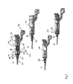
Fig.1 : Hinge mechanism with one bracket for a connection to the vehicle structure and one bracket for a connection to a hood; -
Fig.2 : Lifting mechanism with a locking mechanism in four different positions; -
Fig.3 : An alternative locking mechanism in four different positions. - In
figure 1 it is shown a conventional hinge mechanism to lift the rear edge of ahood 27 of a vehicle. The hinge mechanism comprises twobrackets bracket 2 is attachable to the vehicle structure and onebracket 3 is attached to thehood 27. Thebracket 3 is connected pivotable via arivet 7 to another bracket 4, which are connected via ashear pin 5 and can be seen in normal use as one part. At thebracket 2 is arranged anadjustment bolt 8 which defines the relative position of the bracket 4 to thebracket 2. - The hinge mechanism is further provided with a short lever 1 and a
long lever 11 each connected with one end at the bracket 4 viarivets bracket 2 viarivets - In
figure 2 it is shown alifting mechanism 50 in four different positions. Thelifting mechanism 50 is designed as apiston cylinder unit 60 with twobrackets bracket 21 to be connected via a bolt for example in anaperture 6 at the bracket 4 and with onebracket 24 to be connected via a rivet in along hole 10 at thebracket 2. - The piston cylinder unit 6.0 comprises a
piston 17 with a piston rod 17a which is formed at the end to thebracket 21 connectable to the bracket 4. In one end of thecylinder 16 is arranged a gas generator 22, which is pressurising a pressure chamber 23 when activated. The pressure chamber 23 is closed by thepiston 17, so that thepiston 17 is driven to a movement lifting thehood 27 when the gasgenerator 22 is activated. - The
cylinder 16 is further provided with twooffsets first offset 32 is designed as a ring pressed into thecylinder 16. Between theoffset 31 and thepiston 17 is arranged anenergy absorbing device 18 realised by an elastic rubber element which damps the movement of thepiston 17 at the end of the lifting movement of thehood 27. Instead of the elastic rubber element also a wave shaped metal sheet may be used. - At the piston rod 17a is fixed an
element 25 withfirst barbs 20 andsecond barbs 19. The first andsecond barbs piston 17. Furthermore the diameters of thebarbs first offset 32. The first andsecond barbs first offset 32. Furthermore thebarbs first offset 32. The flat surface of thebarbs element 25 in only one or at least in a limited number of positions relative to thepiston cylinder unit 60 and are easier to manufacture. Theelement 25 may be designed as a clip made of steel or plastic which comprise thebarbs - In the
figure 2 are shown four different positions of thepiston 17 in thecylinder 16 which are representative for different positions A,B,C and D of thehood 27 relative to the vehicle structure. In the position A thepiston 17 is in the initial position before the gasgenerator 22 is actuated. The piston rod 17a is fixed by theelement 25 with thesecond barbs 19 engaging into the opening in thefirst offset 32. Theenergy absorbing device 18 is elongated and not loaded. - When the gasgenerator 22 is actuated a gas pressure is created in the chamber 23 and the
piston 17 is driven into the position B. Theend 21 of the piston rod 17a is moved together with the attached not shownhood 27 in a lifted position. Theelement 25 is moved together with the piston rod 17a and thesecond barbs 19 are pushed through the opening of thefirst offset 32. This position B corresponds to the position of thehood 27 when the pedestrian hits onto thehood 27. During the movement of thepiston 17 from the position A to the position B theenergy absorbing device 18 was pressed together so that the movement was damped especially close before thepiston 17 reached the position B. Theenergy absorbing device 18 is not shown in the positions B,C and D. - After the impact is finished the
hood 27 can be moved backwards towards the vehicle structure before driving to the garage wherein thepiston 17 with the piston rod 17a is moved into thecylinder 16 to the position C and finally to the position D. In the position D thepiston 17 is secured by thefirst barbs 20 which are inserted into the opening in the first offset 32. - In the
figure 3 it is shown a slightly different embodiment of the invention with the piston rod 17a in four different positions E,F,G and H. In the position E thelifting mechanism 50 is in a position where thehood 27 here shown as a part connected with the piston rod 17a is in the position before the actuation of the not shown gas generator 22. The piston rod 17a does not need to be connected directly with thehood 27 but may also be connected to an element which is fixed at thehood 27. The level of the position of thehood 27 is marked with the dashed line L. Thelocking mechanism 40 is designed as aflexible element 25 with first andsecond barbs resilient section 28 which is fixed to a part of thehood 27. In the position E theelement 25 engages with thesecond barbs 30 into anopening 35 of the offset 32. The piston rod 17a comprises at the end a section 17b with a smaller diameter than the piston rod 17a itself so that an offset 17c is provided which use is described later. - After the actuation of the not shown gas generator 22 the piston rod 17a is pushed out of the
cylinder 16 in a first step until thehood 27 is released from theresilient section 28 and thehood 27 is decoupled from thelocking mechanism 40 like shown in the position F. Thefirst barbs 30 still engage into theopening 35 until the piston rod 17a abuts with the offset 17c at the inner diameter of theelement 25. - When the piston rod 17a is pushed further into the position G the
element 25 is pushed because of the abutting offset 17c with thesecond barbs 30 out of thecylinder 16. The position G corresponds to the lifted position of thehood 2 before the impact of the pedestrian. When the pedestrian hits onto thehood 27 in position G of thehood 27, thehood 27 may be moved downwards by pushing thepiston 17 into thecylinder 16 against the pressure in the pressure chamber 23 or be plastically deformed using the created distance between thehood 27 and the vehicle structure. In the most of the cases thehood 27 will be deformed itself and additionally thepiston 17 is pushed backwards into thecylinder 16. Both aspects enable an energy absorbing movement of thehood 27 which reduces the load to the hitting pedestrian and the risk of severe injuries. As theelement 25 is pushed out of thecylinder 16 the pressurised gas in the chamber 23 may escape from thecylinder 16, and thehood 27 can be pushed down in the locked position with a reduced force. - After the impact is finished the
hood 27 may be pushed downwards into the position H. Thelocking mechanism 40 locks thehood 27 in this position H by inserting the first andsecond barbs opening 35 of the offset 32. The offset 32 and the offset 31 are limiting achamber 33 which is used in the position H as a reception for the first andsecond barbs first barbs 29 are loaded in this position H with the total locking load especially as theshear pin 5 fromfigure 1 is broken and theresilient section 28 is released from thehood 27 or a part fixed to thehood 27. Thefirst barbs 29 are designed therefore with a bigger strength than thesecond barbs 30 to withstand the higher forces. - It is clearly visible that the
hood 27 is locked in position H in a lower position compared to the position G and especially close to the position E. The distance of thehood 27 in the position H from the position E is defined by the distance of the first andsecond barbs hood 27 than it was in the position G of the hood. This less limited field of view increases the safety for the driver driving to the garage. As thehood 27 must not be locked in position with the original locking device and only by latching thesecond barbs 30, the force to lock the hood in position H is relatively low and the latching movement from the position G to the position H can be easily performed by hand.
Claims (11)
- Pedestrian protection device for a vehicle comprising a lifting mechanism (50) for lifting the rear edge of a hood (27) of the vehicle in case of an impact with a pedestrian characterised in that the lifting mechanism (50) is provided with a locking mechanism (40) to lock the hood (27) after the actuation of the lifting mechanism (50).
- Pedestrian protection device according to claim 1, characterised in that the locking mechanism (40) is designed to lock the hood (27) in a lower position (H) compared to the position (G) of the hood (27) after the actuation of the lifting mechanism (50).
- Pedestrian protection device according to claim 1 or 2, characterised in that the lifting mechanism (50) is provided with a piston cylinder unit (60) comprising a piston rod (17a) which is guided through an opening (35) of the cylinder (16) wherein a gap is provided between the piston rod (17a) and the opening (35).
- Pedestrian protection device according to claim 3, characterised in that the opening (35) is arranged in a first offset (32) directed into the cylinder (16) and the locking mechanism (50) is designed as an element (25) connected to the piston rod (17a) having first flexible barbs (20,29) latching at the first offset (32) when the hood (27) is locked after the actuation of the lifting mechanism (50) in a first position (H).
- Pedestrian protection device according to claim 4, characterised in that the element (25) comprises second flexible barbs (19,30) latching at the first offset (32) before the actuation of the lifting mechanism (50) when the hood (27) is locked in a second position (E) which is lower than the first position (H).
- Pedestrian protection device according to claim 5, characterised in that the first barbs (20,29) comprise a higher strength than the second barbs (19,30).
- Pedestrian protection device according to claim 5 or 6, characterised in that at least one of the first and/or second barbs (19,20,29,30) comprise a flat surface which corresponds to a flat section of the opening (35).
- Pedestrian protection device according to one of the claims 3 to 7, characterised in that the cylinder (16) comprise a second offset (31) which is directed into the cylinder (16), and an energy absorbing device (18) is provided which is arranged between the piston (17) and the second offset (31).
- Pedestrian protection according to claim 8, characterised in that between the first offset (32) and the second offset (31) is provided a chamber (33) in the cylinder (16) providing a reception for the first and second barbs (19,20,29,30) in the first position (H) of the lifting mechanism (50).
- Pedestrian protection device according to claim 8 or 9, characterised in that the energy absorbing device (18) is designed as a wave shaped deformation element.
- Pedestrian protection device according to claim 8 or 9, characterised in that the energy absorbing device (18) is designed as an elastic rubber element.
Priority Applications (2)
| Application Number | Priority Date | Filing Date | Title |
|---|---|---|---|
| EP10006461A EP2409881B1 (en) | 2010-06-22 | 2010-06-22 | Pedestrian protection device for a vehicle |
| PCT/SE2011/050715 WO2011162675A1 (en) | 2010-06-22 | 2011-06-10 | Pedestrian protection device for a vehicle |
Applications Claiming Priority (1)
| Application Number | Priority Date | Filing Date | Title |
|---|---|---|---|
| EP10006461A EP2409881B1 (en) | 2010-06-22 | 2010-06-22 | Pedestrian protection device for a vehicle |
Publications (2)
| Publication Number | Publication Date |
|---|---|
| EP2409881A1 true EP2409881A1 (en) | 2012-01-25 |
| EP2409881B1 EP2409881B1 (en) | 2013-01-02 |
Family
ID=43128255
Family Applications (1)
| Application Number | Title | Priority Date | Filing Date |
|---|---|---|---|
| EP10006461A Not-in-force EP2409881B1 (en) | 2010-06-22 | 2010-06-22 | Pedestrian protection device for a vehicle |
Country Status (2)
| Country | Link |
|---|---|
| EP (1) | EP2409881B1 (en) |
| WO (1) | WO2011162675A1 (en) |
Families Citing this family (4)
| Publication number | Priority date | Publication date | Assignee | Title |
|---|---|---|---|---|
| CN102700497A (en) * | 2012-06-20 | 2012-10-03 | 湖南大学 | Car engine hood bounce device based on pedestrian head injury protection |
| JP6533407B2 (en) * | 2015-03-31 | 2019-06-19 | Joyson Safety Systems Japan株式会社 | Gas pressure actuator |
| JP6565764B2 (en) * | 2016-03-30 | 2019-08-28 | 豊田合成株式会社 | Actuator |
| DE102020118957A1 (en) | 2020-07-17 | 2022-01-20 | Bayerische Motoren Werke Aktiengesellschaft | ACTUATOR FOR ADJUSTING A FRONT HOOD FROM A NORMAL POSITION TO A PROTECTIVE POSITION |
Citations (8)
| Publication number | Priority date | Publication date | Assignee | Title |
|---|---|---|---|---|
| DE3730808A1 (en) * | 1987-09-14 | 1989-03-23 | Heb Hydraulik Elementebau Gmbh | Locking device for hydraulic or pneumatic working cylinders |
| US20040128998A1 (en) * | 2001-08-17 | 2004-07-08 | Yves Daunas | Autonomous gas powered ram |
| EP1470971A2 (en) * | 2003-04-22 | 2004-10-27 | Nhk Spring Co., Ltd. | Actuator provided with locking mechanism |
| EP1536991B1 (en) | 2002-03-27 | 2006-01-25 | Ford Global Technologies, LLC | A motor vehicle and a hinge assembly therefor |
| DE102004037060A1 (en) * | 2004-07-30 | 2006-03-23 | Trw Automotive Gmbh | Actuating drive for device for raising of engine bonnet of motor vehicle has control unit which automatically triggers return movement of actuating component back into initial position |
| EP1705382A1 (en) * | 2005-03-24 | 2006-09-27 | Mazda Motor Corporation | Vehicle safety device |
| DE102005024350A1 (en) * | 2005-05-27 | 2006-11-30 | Bayerische Motoren Werke Ag | Automobile motor compartment lid lock has a lifter, as a piston operated by a gas generator, triggered by a sensor on collision with a pedestrian/cyclist moving it into a locked intermediate position |
| US20090217814A1 (en) * | 2008-02-28 | 2009-09-03 | Gm Global Technology Operations, Inc. | Pneumatic actuator |
Family Cites Families (4)
| Publication number | Priority date | Publication date | Assignee | Title |
|---|---|---|---|---|
| DE10108880B4 (en) * | 2001-02-23 | 2014-10-30 | Volkswagen Ag | Lifting system |
| DE10301401B4 (en) * | 2002-08-03 | 2007-08-16 | Suspa Holding Gmbh | Lifting device, its use and motor vehicle with a pedestrian protection device |
| JP5024223B2 (en) * | 2007-09-27 | 2012-09-12 | 豊田合成株式会社 | Actuator |
| DE102008011722A1 (en) * | 2008-02-28 | 2009-09-03 | Dr. Ing. H.C. F. Porsche Aktiengesellschaft | Engine bonnet hinge for motor vehicle, has piston held at distant position by connection whose detachability absorbs kinetic energy of pedestrian caught in bonnet by braked displacement from distant position into pivoting position |
-
2010
- 2010-06-22 EP EP10006461A patent/EP2409881B1/en not_active Not-in-force
-
2011
- 2011-06-10 WO PCT/SE2011/050715 patent/WO2011162675A1/en not_active Ceased
Patent Citations (8)
| Publication number | Priority date | Publication date | Assignee | Title |
|---|---|---|---|---|
| DE3730808A1 (en) * | 1987-09-14 | 1989-03-23 | Heb Hydraulik Elementebau Gmbh | Locking device for hydraulic or pneumatic working cylinders |
| US20040128998A1 (en) * | 2001-08-17 | 2004-07-08 | Yves Daunas | Autonomous gas powered ram |
| EP1536991B1 (en) | 2002-03-27 | 2006-01-25 | Ford Global Technologies, LLC | A motor vehicle and a hinge assembly therefor |
| EP1470971A2 (en) * | 2003-04-22 | 2004-10-27 | Nhk Spring Co., Ltd. | Actuator provided with locking mechanism |
| DE102004037060A1 (en) * | 2004-07-30 | 2006-03-23 | Trw Automotive Gmbh | Actuating drive for device for raising of engine bonnet of motor vehicle has control unit which automatically triggers return movement of actuating component back into initial position |
| EP1705382A1 (en) * | 2005-03-24 | 2006-09-27 | Mazda Motor Corporation | Vehicle safety device |
| DE102005024350A1 (en) * | 2005-05-27 | 2006-11-30 | Bayerische Motoren Werke Ag | Automobile motor compartment lid lock has a lifter, as a piston operated by a gas generator, triggered by a sensor on collision with a pedestrian/cyclist moving it into a locked intermediate position |
| US20090217814A1 (en) * | 2008-02-28 | 2009-09-03 | Gm Global Technology Operations, Inc. | Pneumatic actuator |
Also Published As
| Publication number | Publication date |
|---|---|
| EP2409881B1 (en) | 2013-01-02 |
| WO2011162675A1 (en) | 2011-12-29 |
Similar Documents
| Publication | Publication Date | Title |
|---|---|---|
| EP3519276B1 (en) | Steering assembly with positive lock and energy absorption and pyrotechnic actuator | |
| US6588526B1 (en) | Front hood assembly | |
| CN102099238B (en) | Improved adjustable steering column for motor vehicles | |
| US7861818B2 (en) | Restraint system for a hood lift device | |
| US7575273B2 (en) | Bonnet bumpstop for a vehicle | |
| EP2409881B1 (en) | Pedestrian protection device for a vehicle | |
| EP2025576A2 (en) | Steering wheel position adjustment device | |
| EP2045146A1 (en) | Pedestrian Safety Bonnet Latch Structure for a Motor Vehicle | |
| EP1642786A2 (en) | Hood stopper structure for automobile | |
| KR20130099964A (en) | Energy absorbing seat for a vehicle | |
| JP2009202871A (en) | Hinge structure for engine hood having pedestrian protective device | |
| CN111315632B (en) | Steering column for a motor vehicle | |
| DE102015007336B4 (en) | Vehicle hinge for raising a vehicle hood in an accident situation | |
| KR100430903B1 (en) | Vehicular hood hinge structure | |
| EP1842746A1 (en) | A bonnet for a vehicle | |
| US7661496B2 (en) | Motor vehicle comprising a pop-up hood | |
| EP3401472A1 (en) | Resettable locking system for a door handle assembly | |
| WO2016009675A1 (en) | Vehicular pop-up hood device and vehicle | |
| DE102009040405B4 (en) | hinge | |
| EP1842744B1 (en) | A grille and bonnet assembly for a vehicle | |
| KR102020884B1 (en) | Hood hinge device for protecting pedestrian | |
| CN110630125A (en) | Active pedestrian protection front cover hinge system | |
| EP2585351B1 (en) | A buckling-resistant coupling arrangement for rail vehicles | |
| EP2329997B1 (en) | A safety device | |
| WO2011162671A1 (en) | Shock-absorbing coupling arrangement |
Legal Events
| Date | Code | Title | Description |
|---|---|---|---|
| AK | Designated contracting states |
Kind code of ref document: A1 Designated state(s): AL AT BE BG CH CY CZ DE DK EE ES FI FR GB GR HR HU IE IS IT LI LT LU LV MC MK MT NL NO PL PT RO SE SI SK SM TR |
|
| AX | Request for extension of the european patent |
Extension state: BA ME RS |
|
| PUAI | Public reference made under article 153(3) epc to a published international application that has entered the european phase |
Free format text: ORIGINAL CODE: 0009012 |
|
| 17P | Request for examination filed |
Effective date: 20120326 |
|
| GRAP | Despatch of communication of intention to grant a patent |
Free format text: ORIGINAL CODE: EPIDOSNIGR1 |
|
| GRAS | Grant fee paid |
Free format text: ORIGINAL CODE: EPIDOSNIGR3 |
|
| GRAP | Despatch of communication of intention to grant a patent |
Free format text: ORIGINAL CODE: EPIDOSNIGR1 |
|
| GRAA | (expected) grant |
Free format text: ORIGINAL CODE: 0009210 |
|
| AK | Designated contracting states |
Kind code of ref document: B1 Designated state(s): AL AT BE BG CH CY CZ DE DK EE ES FI FR GB GR HR HU IE IS IT LI LT LU LV MC MK MT NL NO PL PT RO SE SI SK SM TR |
|
| REG | Reference to a national code |
Ref country code: GB Ref legal event code: FG4D |
|
| REG | Reference to a national code |
Ref country code: AT Ref legal event code: REF Ref document number: 591411 Country of ref document: AT Kind code of ref document: T Effective date: 20130115 Ref country code: CH Ref legal event code: EP |
|
| REG | Reference to a national code |
Ref country code: IE Ref legal event code: FG4D |
|
| REG | Reference to a national code |
Ref country code: DE Ref legal event code: R096 Ref document number: 602010004356 Country of ref document: DE Effective date: 20130228 |
|
| REG | Reference to a national code |
Ref country code: AT Ref legal event code: MK05 Ref document number: 591411 Country of ref document: AT Kind code of ref document: T Effective date: 20130102 |
|
| REG | Reference to a national code |
Ref country code: NL Ref legal event code: VDEP Effective date: 20130102 |
|
| PG25 | Lapsed in a contracting state [announced via postgrant information from national office to epo] |
Ref country code: SI Free format text: LAPSE BECAUSE OF FAILURE TO SUBMIT A TRANSLATION OF THE DESCRIPTION OR TO PAY THE FEE WITHIN THE PRESCRIBED TIME-LIMIT Effective date: 20130102 |
|
| REG | Reference to a national code |
Ref country code: LT Ref legal event code: MG4D |
|
| PG25 | Lapsed in a contracting state [announced via postgrant information from national office to epo] |
Ref country code: IS Free format text: LAPSE BECAUSE OF FAILURE TO SUBMIT A TRANSLATION OF THE DESCRIPTION OR TO PAY THE FEE WITHIN THE PRESCRIBED TIME-LIMIT Effective date: 20130502 Ref country code: CZ Free format text: LAPSE BECAUSE OF FAILURE TO SUBMIT A TRANSLATION OF THE DESCRIPTION OR TO PAY THE FEE WITHIN THE PRESCRIBED TIME-LIMIT Effective date: 20130102 Ref country code: BG Free format text: LAPSE BECAUSE OF FAILURE TO SUBMIT A TRANSLATION OF THE DESCRIPTION OR TO PAY THE FEE WITHIN THE PRESCRIBED TIME-LIMIT Effective date: 20130402 Ref country code: SE Free format text: LAPSE BECAUSE OF FAILURE TO SUBMIT A TRANSLATION OF THE DESCRIPTION OR TO PAY THE FEE WITHIN THE PRESCRIBED TIME-LIMIT Effective date: 20130102 Ref country code: ES Free format text: LAPSE BECAUSE OF FAILURE TO SUBMIT A TRANSLATION OF THE DESCRIPTION OR TO PAY THE FEE WITHIN THE PRESCRIBED TIME-LIMIT Effective date: 20130413 Ref country code: NO Free format text: LAPSE BECAUSE OF FAILURE TO SUBMIT A TRANSLATION OF THE DESCRIPTION OR TO PAY THE FEE WITHIN THE PRESCRIBED TIME-LIMIT Effective date: 20130402 Ref country code: LT Free format text: LAPSE BECAUSE OF FAILURE TO SUBMIT A TRANSLATION OF THE DESCRIPTION OR TO PAY THE FEE WITHIN THE PRESCRIBED TIME-LIMIT Effective date: 20130102 Ref country code: AT Free format text: LAPSE BECAUSE OF FAILURE TO SUBMIT A TRANSLATION OF THE DESCRIPTION OR TO PAY THE FEE WITHIN THE PRESCRIBED TIME-LIMIT Effective date: 20130102 Ref country code: BE Free format text: LAPSE BECAUSE OF FAILURE TO SUBMIT A TRANSLATION OF THE DESCRIPTION OR TO PAY THE FEE WITHIN THE PRESCRIBED TIME-LIMIT Effective date: 20130102 |
|
| PG25 | Lapsed in a contracting state [announced via postgrant information from national office to epo] |
Ref country code: GR Free format text: LAPSE BECAUSE OF FAILURE TO SUBMIT A TRANSLATION OF THE DESCRIPTION OR TO PAY THE FEE WITHIN THE PRESCRIBED TIME-LIMIT Effective date: 20130403 Ref country code: PT Free format text: LAPSE BECAUSE OF FAILURE TO SUBMIT A TRANSLATION OF THE DESCRIPTION OR TO PAY THE FEE WITHIN THE PRESCRIBED TIME-LIMIT Effective date: 20130502 Ref country code: NL Free format text: LAPSE BECAUSE OF FAILURE TO SUBMIT A TRANSLATION OF THE DESCRIPTION OR TO PAY THE FEE WITHIN THE PRESCRIBED TIME-LIMIT Effective date: 20130102 Ref country code: FI Free format text: LAPSE BECAUSE OF FAILURE TO SUBMIT A TRANSLATION OF THE DESCRIPTION OR TO PAY THE FEE WITHIN THE PRESCRIBED TIME-LIMIT Effective date: 20130102 Ref country code: PL Free format text: LAPSE BECAUSE OF FAILURE TO SUBMIT A TRANSLATION OF THE DESCRIPTION OR TO PAY THE FEE WITHIN THE PRESCRIBED TIME-LIMIT Effective date: 20130102 Ref country code: LV Free format text: LAPSE BECAUSE OF FAILURE TO SUBMIT A TRANSLATION OF THE DESCRIPTION OR TO PAY THE FEE WITHIN THE PRESCRIBED TIME-LIMIT Effective date: 20130102 |
|
| PG25 | Lapsed in a contracting state [announced via postgrant information from national office to epo] |
Ref country code: HR Free format text: LAPSE BECAUSE OF FAILURE TO SUBMIT A TRANSLATION OF THE DESCRIPTION OR TO PAY THE FEE WITHIN THE PRESCRIBED TIME-LIMIT Effective date: 20130102 |
|
| PG25 | Lapsed in a contracting state [announced via postgrant information from national office to epo] |
Ref country code: EE Free format text: LAPSE BECAUSE OF FAILURE TO SUBMIT A TRANSLATION OF THE DESCRIPTION OR TO PAY THE FEE WITHIN THE PRESCRIBED TIME-LIMIT Effective date: 20130102 Ref country code: SK Free format text: LAPSE BECAUSE OF FAILURE TO SUBMIT A TRANSLATION OF THE DESCRIPTION OR TO PAY THE FEE WITHIN THE PRESCRIBED TIME-LIMIT Effective date: 20130102 Ref country code: RO Free format text: LAPSE BECAUSE OF FAILURE TO SUBMIT A TRANSLATION OF THE DESCRIPTION OR TO PAY THE FEE WITHIN THE PRESCRIBED TIME-LIMIT Effective date: 20130102 Ref country code: DK Free format text: LAPSE BECAUSE OF FAILURE TO SUBMIT A TRANSLATION OF THE DESCRIPTION OR TO PAY THE FEE WITHIN THE PRESCRIBED TIME-LIMIT Effective date: 20130102 |
|
| PLBE | No opposition filed within time limit |
Free format text: ORIGINAL CODE: 0009261 |
|
| STAA | Information on the status of an ep patent application or granted ep patent |
Free format text: STATUS: NO OPPOSITION FILED WITHIN TIME LIMIT |
|
| PG25 | Lapsed in a contracting state [announced via postgrant information from national office to epo] |
Ref country code: CY Free format text: LAPSE BECAUSE OF FAILURE TO SUBMIT A TRANSLATION OF THE DESCRIPTION OR TO PAY THE FEE WITHIN THE PRESCRIBED TIME-LIMIT Effective date: 20130102 |
|
| 26N | No opposition filed |
Effective date: 20131003 |
|
| PG25 | Lapsed in a contracting state [announced via postgrant information from national office to epo] |
Ref country code: IT Free format text: LAPSE BECAUSE OF FAILURE TO SUBMIT A TRANSLATION OF THE DESCRIPTION OR TO PAY THE FEE WITHIN THE PRESCRIBED TIME-LIMIT Effective date: 20130102 |
|
| REG | Reference to a national code |
Ref country code: DE Ref legal event code: R097 Ref document number: 602010004356 Country of ref document: DE Effective date: 20131003 |
|
| PG25 | Lapsed in a contracting state [announced via postgrant information from national office to epo] |
Ref country code: MC Free format text: LAPSE BECAUSE OF FAILURE TO SUBMIT A TRANSLATION OF THE DESCRIPTION OR TO PAY THE FEE WITHIN THE PRESCRIBED TIME-LIMIT Effective date: 20130102 |
|
| REG | Reference to a national code |
Ref country code: IE Ref legal event code: MM4A |
|
| PG25 | Lapsed in a contracting state [announced via postgrant information from national office to epo] |
Ref country code: IE Free format text: LAPSE BECAUSE OF NON-PAYMENT OF DUE FEES Effective date: 20130622 |
|
| PGFP | Annual fee paid to national office [announced via postgrant information from national office to epo] |
Ref country code: FR Payment date: 20140407 Year of fee payment: 5 |
|
| REG | Reference to a national code |
Ref country code: CH Ref legal event code: PL |
|
| GBPC | Gb: european patent ceased through non-payment of renewal fee |
Effective date: 20140622 |
|
| PG25 | Lapsed in a contracting state [announced via postgrant information from national office to epo] |
Ref country code: MT Free format text: LAPSE BECAUSE OF FAILURE TO SUBMIT A TRANSLATION OF THE DESCRIPTION OR TO PAY THE FEE WITHIN THE PRESCRIBED TIME-LIMIT Effective date: 20130102 |
|
| PG25 | Lapsed in a contracting state [announced via postgrant information from national office to epo] |
Ref country code: LI Free format text: LAPSE BECAUSE OF NON-PAYMENT OF DUE FEES Effective date: 20140630 Ref country code: CH Free format text: LAPSE BECAUSE OF NON-PAYMENT OF DUE FEES Effective date: 20140630 |
|
| PG25 | Lapsed in a contracting state [announced via postgrant information from national office to epo] |
Ref country code: SM Free format text: LAPSE BECAUSE OF FAILURE TO SUBMIT A TRANSLATION OF THE DESCRIPTION OR TO PAY THE FEE WITHIN THE PRESCRIBED TIME-LIMIT Effective date: 20130102 Ref country code: GB Free format text: LAPSE BECAUSE OF NON-PAYMENT OF DUE FEES Effective date: 20140622 |
|
| PG25 | Lapsed in a contracting state [announced via postgrant information from national office to epo] |
Ref country code: TR Free format text: LAPSE BECAUSE OF FAILURE TO SUBMIT A TRANSLATION OF THE DESCRIPTION OR TO PAY THE FEE WITHIN THE PRESCRIBED TIME-LIMIT Effective date: 20130102 |
|
| PG25 | Lapsed in a contracting state [announced via postgrant information from national office to epo] |
Ref country code: LU Free format text: LAPSE BECAUSE OF NON-PAYMENT OF DUE FEES Effective date: 20130622 Ref country code: HU Free format text: LAPSE BECAUSE OF FAILURE TO SUBMIT A TRANSLATION OF THE DESCRIPTION OR TO PAY THE FEE WITHIN THE PRESCRIBED TIME-LIMIT; INVALID AB INITIO Effective date: 20100622 Ref country code: MK Free format text: LAPSE BECAUSE OF FAILURE TO SUBMIT A TRANSLATION OF THE DESCRIPTION OR TO PAY THE FEE WITHIN THE PRESCRIBED TIME-LIMIT Effective date: 20130102 |
|
| PGFP | Annual fee paid to national office [announced via postgrant information from national office to epo] |
Ref country code: DE Payment date: 20150413 Year of fee payment: 6 |
|
| REG | Reference to a national code |
Ref country code: FR Ref legal event code: ST Effective date: 20160229 |
|
| PG25 | Lapsed in a contracting state [announced via postgrant information from national office to epo] |
Ref country code: FR Free format text: LAPSE BECAUSE OF NON-PAYMENT OF DUE FEES Effective date: 20150630 |
|
| REG | Reference to a national code |
Ref country code: DE Ref legal event code: R119 Ref document number: 602010004356 Country of ref document: DE |
|
| PG25 | Lapsed in a contracting state [announced via postgrant information from national office to epo] |
Ref country code: DE Free format text: LAPSE BECAUSE OF NON-PAYMENT OF DUE FEES Effective date: 20170103 |
|
| PG25 | Lapsed in a contracting state [announced via postgrant information from national office to epo] |
Ref country code: AL Free format text: LAPSE BECAUSE OF FAILURE TO SUBMIT A TRANSLATION OF THE DESCRIPTION OR TO PAY THE FEE WITHIN THE PRESCRIBED TIME-LIMIT Effective date: 20130102 |