EP2409779B1 - Paint booth equipped with purification device - Google Patents
Paint booth equipped with purification device Download PDFInfo
- Publication number
- EP2409779B1 EP2409779B1 EP10774822.0A EP10774822A EP2409779B1 EP 2409779 B1 EP2409779 B1 EP 2409779B1 EP 10774822 A EP10774822 A EP 10774822A EP 2409779 B1 EP2409779 B1 EP 2409779B1
- Authority
- EP
- European Patent Office
- Prior art keywords
- water
- conveyor
- paint
- water tank
- spray chamber
- Prior art date
- Legal status (The legal status is an assumption and is not a legal conclusion. Google has not performed a legal analysis and makes no representation as to the accuracy of the status listed.)
- Not-in-force
Links
Images

Classifications
-
- B—PERFORMING OPERATIONS; TRANSPORTING
- B01—PHYSICAL OR CHEMICAL PROCESSES OR APPARATUS IN GENERAL
- B01D—SEPARATION
- B01D47/00—Separating dispersed particles from gases, air or vapours by liquid as separating agent
- B01D47/02—Separating dispersed particles from gases, air or vapours by liquid as separating agent by passing the gas or air or vapour over or through a liquid bath
- B01D47/022—Separating dispersed particles from gases, air or vapours by liquid as separating agent by passing the gas or air or vapour over or through a liquid bath by using a liquid curtain
-
- B—PERFORMING OPERATIONS; TRANSPORTING
- B01—PHYSICAL OR CHEMICAL PROCESSES OR APPARATUS IN GENERAL
- B01D—SEPARATION
- B01D53/00—Separation of gases or vapours; Recovering vapours of volatile solvents from gases; Chemical or biological purification of waste gases, e.g. engine exhaust gases, smoke, fumes, flue gases, aerosols
- B01D53/34—Chemical or biological purification of waste gases
- B01D53/74—General processes for purification of waste gases; Apparatus or devices specially adapted therefor
- B01D53/77—Liquid phase processes
- B01D53/78—Liquid phase processes with gas-liquid contact
-
- B—PERFORMING OPERATIONS; TRANSPORTING
- B05—SPRAYING OR ATOMISING IN GENERAL; APPLYING FLUENT MATERIALS TO SURFACES, IN GENERAL
- B05B—SPRAYING APPARATUS; ATOMISING APPARATUS; NOZZLES
- B05B14/00—Arrangements for collecting, re-using or eliminating excess spraying material
- B05B14/40—Arrangements for collecting, re-using or eliminating excess spraying material for use in spray booths
- B05B14/46—Arrangements for collecting, re-using or eliminating excess spraying material for use in spray booths by washing the air charged with excess material
- B05B14/462—Arrangements for collecting, re-using or eliminating excess spraying material for use in spray booths by washing the air charged with excess material and separating the excess material from the washing liquid, e.g. for recovery
-
- B—PERFORMING OPERATIONS; TRANSPORTING
- B05—SPRAYING OR ATOMISING IN GENERAL; APPLYING FLUENT MATERIALS TO SURFACES, IN GENERAL
- B05B—SPRAYING APPARATUS; ATOMISING APPARATUS; NOZZLES
- B05B14/00—Arrangements for collecting, re-using or eliminating excess spraying material
- B05B14/40—Arrangements for collecting, re-using or eliminating excess spraying material for use in spray booths
- B05B14/46—Arrangements for collecting, re-using or eliminating excess spraying material for use in spray booths by washing the air charged with excess material
- B05B14/465—Arrangements for collecting, re-using or eliminating excess spraying material for use in spray booths by washing the air charged with excess material using substantially vertical liquid curtains or wetted walls behind the object to be sprayed
-
- B—PERFORMING OPERATIONS; TRANSPORTING
- B05—SPRAYING OR ATOMISING IN GENERAL; APPLYING FLUENT MATERIALS TO SURFACES, IN GENERAL
- B05B—SPRAYING APPARATUS; ATOMISING APPARATUS; NOZZLES
- B05B14/00—Arrangements for collecting, re-using or eliminating excess spraying material
- B05B14/40—Arrangements for collecting, re-using or eliminating excess spraying material for use in spray booths
- B05B14/46—Arrangements for collecting, re-using or eliminating excess spraying material for use in spray booths by washing the air charged with excess material
- B05B14/469—Arrangements for collecting, re-using or eliminating excess spraying material for use in spray booths by washing the air charged with excess material wherein the washing material is the spraying material
-
- B—PERFORMING OPERATIONS; TRANSPORTING
- B01—PHYSICAL OR CHEMICAL PROCESSES OR APPARATUS IN GENERAL
- B01D—SEPARATION
- B01D2247/00—Details relating to the separation of dispersed particles from gases, air or vapours by liquid as separating agent
- B01D2247/04—Regenerating the washing fluid
-
- B—PERFORMING OPERATIONS; TRANSPORTING
- B01—PHYSICAL OR CHEMICAL PROCESSES OR APPARATUS IN GENERAL
- B01D—SEPARATION
- B01D2247/00—Details relating to the separation of dispersed particles from gases, air or vapours by liquid as separating agent
- B01D2247/10—Means for removing the washing fluid dispersed in the gas or vapours
- B01D2247/105—Means for removing the washing fluid dispersed in the gas or vapours by gas flow reversal
-
- B—PERFORMING OPERATIONS; TRANSPORTING
- B01—PHYSICAL OR CHEMICAL PROCESSES OR APPARATUS IN GENERAL
- B01D—SEPARATION
- B01D2247/00—Details relating to the separation of dispersed particles from gases, air or vapours by liquid as separating agent
- B01D2247/14—Fan arrangements for providing induced draft
-
- Y—GENERAL TAGGING OF NEW TECHNOLOGICAL DEVELOPMENTS; GENERAL TAGGING OF CROSS-SECTIONAL TECHNOLOGIES SPANNING OVER SEVERAL SECTIONS OF THE IPC; TECHNICAL SUBJECTS COVERED BY FORMER USPC CROSS-REFERENCE ART COLLECTIONS [XRACs] AND DIGESTS
- Y02—TECHNOLOGIES OR APPLICATIONS FOR MITIGATION OR ADAPTATION AGAINST CLIMATE CHANGE
- Y02P—CLIMATE CHANGE MITIGATION TECHNOLOGIES IN THE PRODUCTION OR PROCESSING OF GOODS
- Y02P70/00—Climate change mitigation technologies in the production process for final industrial or consumer products
- Y02P70/10—Greenhouse gas [GHG] capture, material saving, heat recovery or other energy efficient measures, e.g. motor control, characterised by manufacturing processes, e.g. for rolling metal or metal working
Definitions
- This invention relates to a paint booth with a purifier for removing paint mist contained in air in a spray chamber.
- a paint booth is used for painting operation by means of a paint sprayer such as a spray nozzle in a spray chamber.
- the paint booth is used to prevent a working environment in the spray chamber from getting worse or prevent paint mist from being discharged to the outside.
- a paint booth of the Venturi booth type is disclosed in, for example, Jpn. Pat. Appln. KOKAI Publication No. 2002-273292 (Patent Document 1).
- air containing paint mist is drawn into an eddy chamber by an exhaust fan.
- the paint mist is separated from airflow by means of centrifugal force of the air produced in the eddy chamber, and the paint mist is collected as it impinges on a water film.
- the water containing the collected paint mist is returned from a submerged duct to a water tank and reused.
- the moist air discharged from the eddy chamber is discharged through an exhaust port after it is dehydrated by an eliminator.
- a paint booth of the water booth type is disclosed in Japanese Patent No. 3704084 (Patent Document 2).
- Patent Document 2 a water curtain is formed by pouring water drawn up by a pump in the form of a film along a water flow plate. The paint mist is washed away when it contacts the water curtain. Further, shower water is sprayed from shower nozzles arranged on the back side of the water flow plate. By this shower water, the paint mist having failed to be collected by the water curtain is dropped into water.
- paint sludge paint residue
- This paint sludge collects in the water tank, floating on the water surface or settling in the water tank. Since the conventional paint booths do not comprise a mechanism for purifying water in the water tank, an operator or operators periodically manually remove the paint sludge. However, the periodic cleaning cannot purify contaminated water unless the water is changed. Accordingly, the paint sludge gradually collects in the water tank and solidifies at the bottom of the water tank or near the water surface. Thus, the paint sludge cannot be easily removed and causes contamination of the paint booth.
- Patent Document 1 In the conventional Venturi booth type (Patent Document 1), moreover, a strong negative pressure must be produced to draw up water into the eddy chamber. A large-capacity exhaust fan is needed to attain this, resulting in problems of loud noise, high energy consumption, etc.
- Patent Document 2 In the conventional water booth type (Patent Document 2), in contrast, the paint mist contacts only one surface of the water curtain. Therefore, the surface area of the water curtain that can collect the paint mist is small. Thus, the conventional water booth type has a small capacity to collect the paint mist. To increase the collection capacity, a wider water curtain is required, so that the paint booth is enlarged, and a problem of necessity of a large-capacity pump or the like occurs.
- the object of the present invention is to provide a paint booth with a high-capacity purifier, capable of efficiently collecting paint mist despite its compactness compared with that of a conventional paint booth.
- a paint booth with a purifier comprises a spray chamber accommodating an object to be painted and a purifier for removing paint mist contained in air in the spray chamber.
- the purifier comprises a water tank disposed in the spray chamber, a pump which draws up water in the water tank, and a water cord formation mechanism.
- the water cord formation mechanism comprises a water case for accommodating the water drawn up by the pump.
- the water case comprises a bottom wall formed with a plurality of nozzles, each of the nozzles comprising an inlet, a tubular portion protruding downward from the bottom wall in such a manner that the inside diameter of the tubular portion is reduced downward from the inlet, and a circular outlet opening at the lower end of the tubular portion.
- the water which drops in straight lines from the outlets forms a plurality of parallel water cords.
- the purifier comprises a barrier member, splashguard member, exhaust chamber separated from the spray chamber by the barrier member, exhaust mechanism, and sludge removal mechanism.
- the barrier member comprises a vertically extending wall portion.
- the splashguard member is located above a water surface of the water tank and opposite and just below the nozzles and comprises a water receiving surface which declines from an upper end portion in front of the water cords toward a lower end portion near the barrier member.
- the exhaust mechanism comprises an exhaust fan for discharging the air in the spray chamber to the outside through the exhaust chamber and produces airflow such that the air containing the paint mist in the spray chamber contacts the water cords.
- the sludge removal mechanism comprises a conveyor disposed in the water tank and discharges paint sludge in the water tank to the outside of the water tank.
- the nozzles of the water cord formation mechanism are formed in, for example, positions corresponding to vertices of equilateral triangles such that distances between the nozzles are equal to one another as viewed from above the water case.
- the nozzles may be arranged in a different way.
- the paint booth comprises a water shedder which is located above the conveyor positioned below the splashguard member and extends along the conveyor.
- the water shedder comprises a top portion located below a gap between the barrier member and the splashguard member, a first guide surface which declines from the top portion toward one chain of the conveyor, and a second guide surface which declines from the top portion toward the other chain of the conveyor.
- An example of the conveyor comprises an upper portion movable near the water surface of the water tank and a lower portion movable near a bottom portion of the water tank. Paint sludge near the water surface is conveyed to a sludge discharge portion outside the water tank by means of the upper portion.
- An example of the conveyor is movable in a first direction and a second direction opposite to the first direction. When the conveyor moves in the first direction, the paint sludge near the water surface is conveyed toward the sludge discharge portion by the upper portion. When the conveyor moves in the second direction, the paint sludge at the bottom portion of the water tank is conveyed toward the sludge discharge portion by the lower portion.
- water surface height maintenance means should preferably be provided for locating the water surface of the water tank at the upper portion of the conveyor.
- the sludge removal mechanism comprises, for example, a filter drum, scraping member, and cleaned-fluid tank.
- the filter drum is disposed for rotation in the water tank and causes the water in the water tank to flow in from the outer peripheral side to the inner peripheral side of the drum, thereby filtering the water in the water tank.
- the scraping member prevents clogging of the filter drum by contacting the peripheral surfaces of the filter drum.
- the cleaned-fluid tank introduces the water filtered by the filter drum into the pump.
- the paint booth may comprise water curtain forming means.
- the water curtain forming means causes the water to flow along the barrier member, thereby forming a water curtain behind the water cords. Some of the paint mist can be captured by means of the water curtain in a state where the air with the paint mist is contacting with the water curtain.
- the surface area of the water that can be contacted by the paint mist can be made larger than in a conventional paint booth.
- the paint mist can be efficiently collected even if the capacity of the pump is small.
- the capacity of the exhaust fan can be smaller than in the case of the conventional paint booth of the Venturi booth type or water booth type. This leads to advantages of energy conservation and reduced noise.
- the water cord formation mechanism according to the present invention is configured so that a large number of water cords are formed by water continuously dropping in straight lines individually from a large number of nozzles formed in the bottom wall of the water case. These water cords drop straight along the vertical wall portion of the barrier member toward the splashguard member. Even when an operator in the spray chamber is working near the water cords, therefore, an environment can be maintained such that he/she cannot be easily wetted by water. Thus, there is an advantage that the space in the spray chamber can be used effectively. Since the water dropping from the nozzles is received by the splashguard member, moreover, the water surface in the water tank can be prevented from positively undulating. In this purifier, therefore, the paint sludge can easily float on the water surface, and the paint sludge floating on the water surface can be efficiently carried out by the conveyor.
- FIGS. 1 to 6 One embodiment of the present invention will now be described with reference to FIGS. 1 to 6 .
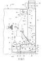
- FIG. 1 is a vertical sectional view of a paint booth 10.
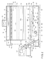
- FIG. 2 is a sectional view of the paint booth 10 taken in the direction of arrow F2-F2 in FIG. 1 .
- the paint booth 10 comprises a spray chamber 11, in which paining operation is performed, and a purifier 12.
- the purifier 12 has the function of removing paint mist M (schematically shown in FIG. 1 ) produced in the spray chamber 11.
- the spray chamber 11 is isolated from the external environment by a wall member 13, ceiling member, etc., which are substantially sealed.
- a paint sprayer with a spray nozzle 15 and an object 16 to be painted are accommodated in the spray chamber 11.
- An atomized paint sprayed from the spray nozzle 15 forms the paint mist M.
- the purifier 12 has the function of removing the paint mist M contained in air in the spray chamber 11. The following is a description of the purifier 12.
- the purifier 12 comprises a water tank 20, pump 21, water cord formation mechanism 22, sludge removal mechanism 26 comprising a conveyor 25, exhaust mechanism 28, etc.
- the water tank 20 is located in a lower part of the spray chamber 11.
- the pump 21 draws up water W in the water tank 20.
- the water cord formation mechanism 22, sludge removal mechanism 26, and exhaust mechanism 28 will be described in detail later.
- the water tank 20 comprises a tank body 30 accommodating the conveyor 25 and cleaned-fluid tank 31 accommodating filtered water.
- the cleaned-fluid tank 31 is provided with the pump 21.
- the tank body 30 and cleaned-fluid tank 31 communicate with each other through a flow passage 32.
- the water cord formation mechanism 22 comprises a gutter-like water case 40 located above the water tank 20 and a cushion tank 41 located along the water case 40.
- a water flow suppression member 43 ( FIG. 2 ) formed of a porous plate of, for example, a punching metal is interposed between the water case 40 and cushion tank 41.
- the water W drawn up by the pump 21 is introduced into the cushion tank 41 through a piping system 42a, which comprises a valve 42 ( FIG. 2 ), and a cushion tank inlet portion 41a.
- the water W introduced into the cushion tank 41 flows into the water case 40 through the water flow suppression member 43.
- the water case 40 and cushion tank 41 is each formed of a metal plate of stainless steel or the like. As shown in FIG. 2 , the water case 40 and cushion tank 41 horizontally extend substantially throughout the entire transverse length of the spray chamber 11.
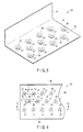
- FIG. 3 shows a part of the water case 40.
- the water case 40 comprises a horizontally extending bottom wall 45 and sidewalls 46.
- the sidewalls 46 extend upward from the side edges of the bottom wall 45.
- a horizontally extending slit 47 is formed in the sidewall 46.
- the bottom wall 45 and sidewalls 46 are formed substantially throughout the entire transverse length of the spray chamber 11.
- a large number of nozzles 50 are formed at regular intervals in the bottom wall 45 of the water case 40.
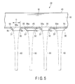
- FIG. 4 is a top plan view of the bottom wall 45 of the water case 40 comprising the nozzles 50.
- the nozzles 50 in the bottom wall 45 of the water case 40 are formed in, for example, positions corresponding to vertices ( FIG. 4 ) of equilateral triangles 51 as viewed from above, such that the distances between them are all equal. Thus, distances S between the nozzles 50 are all equal.
- the nozzles 50 may be arranged in a way different from that in the embodiment shown in FIG. 4 . In short, the nozzles 50 should only be arranged at regular intervals. Although the nozzles 50 are arranged in three rows in the embodiment shown in FIG. 4 , they may alternatively be arranged in, for example, two rows or three or more rows. In short, the nozzles 50 should only be arranged in one or more rows.
- FIG. 5 shows a vertical cross-section of the nozzles 50.
- each nozzle 50 comprises an inlet 55, tubular portion 56 protruding downward from the bottom wall 45, and outlet 57.
- the inlet 55 opens in the upper surface of the bottom wall 45 of the water case 40.
- the tubular portion 56 has its inside diameter D reduced downward from the inlet 55 as it extends downward.
- the outlet 57 opens at the lower end of the tubular portion 56.
- the inlet 55 and outlet 57 are circular as viewed from above.
- the inlet 55 and outlet 57 are formed in such a manner that the outlet 57 forms a concentric circle within the inlet 55 as viewed from above.
- an inner peripheral surface 56a of the tubular portion 56 is a smoothly continuously curved surface extending in a circular arc from the inlet 55 to the outlet 57. That part in which the inlet 55 connects with the inner peripheral surface 56a of the tubular portion 56 has a smooth round shape such that flowing water does not cause turbulence.
- the lower end surface of the tubular portion 56 is finished horizontally flat such that it is free from cracks, distortion, etc., and does not cause turbulence.
- the nozzles 50 thus shaped can be formed by combining burring, which is a kind of plastic working using a die, with finishing.
- the water W is introduced onto the bottom wall 45 of the water case 40 with the nozzles 50.
- the water W flows into the tubular portions 56 through the inlets 55 and further freely drops down through the outlets 57.
- the water that drops through the respective outlets 57 of the nozzles 50 falls straight downward without causing turbulence.
- the water can flow in substantially continuous linear streams, thereby forming cord-like water columns, at least when it is on the way to reach the water tank 20 through the outlets 57. This is the source of the term "water cord (water rope) 60" used herein.
- each nozzle 50 Since the dropping speed increases as the water goes down, the water cords 60 are gradually tapered downward.
- the tubular portion 56 of each nozzle 50 has a curved surface such that the water flowing therein cannot easily cause turbulence. Accordingly, the water can flow in substantially continuous linear streams until just before it reaches the water tank 20.
- the water cords 60 dropping through the respective outlets 57 of the nozzles 50 are kept parallel to one another, and the distances between the dropping water cords 60 are equal to one another. Consequently, a group of water columns, comprising a large number of water cords 60, is formed between the water case 40 and water tank 20 without allowing the water cords 60 to join one another.
- a vertically extending barrier member 70 of sheet metal is located in the rear part of the spray chamber 11 (or behind the water cords 60). As shown in FIG. 1 , the interior of the paint booth 10 is divided between the spray chamber 11 and an exhaust chamber 71 by the barrier member 70.
- the barrier member 70 is formed of a metal plate such as stainless steel.
- the barrier member 70 comprises a wall portion 70a and bent portion 70b.
- the wall portion 70a vertically extends along the water cords 60.
- the bent portion 70b is curved from the lower part of the wall portion 70a toward the exhaust chamber 71.
- the barrier member 70 is disposed substantially covering the entire transverse length of the spray chamber 11.
- the water drawn up by the pump 21 is introduced into the water case 40. Some of the water introduced into the water case 40 flows out through the slit 47 toward the barrier member 70.
- the slit 47 is formed in the sidewall 46 of the water case 40.
- the water having reached the barrier member 70 flows down along the front surface of the wall portion 70a of the barrier member 70. Thereupon, a water curtain 75 of flowing water is formed behind the water cords 60.
- the slit 47 and wall portion 70a function as water curtain forming means.
- a splashguard member 80 of sheet metal is located above a water surface W1 of the water tank 20 and opposite and just below the nozzles 50.
- the splashguard member 80 is also disposed substantially covering the entire transverse length of the spray chamber 11.
- the splashguard member 80 comprises an upper end portion 80a located in front of the water cords 60, lower end portion 80b located near the barrier member 70, and water receiving surface 81.
- the water receiving surface 81 is inclined at angle ⁇ such that it declines from the upper end portion 80a of the splashguard member 80 toward the lower end portion 80b.
- a slit-like gap 82 is formed between the lower end portion 80b of the splashguard member 80 and the bent portion 70b of the barrier member 70.
- the gap 82 extends horizontally and is formed substantially throughout the entire transverse length of the spray chamber 11.
- a water shedder 90 is located below the splashguard member 80.
- the water shedder 90 is disposed above the conveyor 25 such that it extends in the moving direction of the conveyor 25.
- the water shedder 90 is also formed of a metal plate such as stainless steel and disposed substantially covering the entire transverse length of the spray chamber 11.
- the water shedder 90 has an upwardly convex shape, and a ridge-like top portion 91 is formed in its highest position.
- the top portion 91 is located below the gap 82 between the barrier member 70 and splashguard member 80.
- the water shedder 90 comprises a first guide surface 92 and second guide surface 93.
- the first guide surface 92 declines from the top portion 91 toward one chain 25a of the conveyor 25.
- the second guide surface 93 declines from the top portion 91 toward the other chain 25b of the conveyor 25.
- a gap 95 is formed between the lower end of the bent portion 70b of the barrier member 70 and the water shedder 90.
- the gap 95 like the aforementioned gap 82, extends continuously and horizontally and is formed substantially throughout the entire transverse length of the spray chamber 11.
- the spray chamber 11 and exhaust chamber 71 communicate with each other through the gaps 82 and 95.
- the exhaust mechanism 28 comprises the exhaust chamber 71, an exhaust fan 100 located in the upper part of the exhaust chamber 71, eliminators 101 arranged in a plurality of positions in the exhaust chamber 71, etc.
- the exhaust fan 100 is driven by a motor 102 and discharges air in the spray chamber 11 to the outside through the exhaust chamber 71.
- This exhaust mechanism 28 has the function of producing an airflow in the spray chamber 11 such that air containing the paint mist in the spray chamber 11 can contact the water cords 60 and water curtain 75.
- the sludge removal mechanism 26 comprises the conveyor 25 accommodated in the water tank 20, a filter drum 110 located below the water surface W1 of the water tank 20, and the like.
- a lift portion 115 extending obliquely upward is formed on a side portion of the water tank 20.
- a sludge discharge portion 116 and motor 117 for driving the conveyor 25 are arranged at the upper part of the lift portion 115.
- the sludge discharge portion 116 and motor 117 are located higher than the water surface W1 of the water tank 20.
- a sludge collection box 120 is placed below the sludge discharge portion 116.
- the conveyor 25 comprises the chains 25a and 25b ( FIG. 1 ) as an example of wrapped-around transmission members and a plurality of scrapers 125.
- the scrapers 125 are mounted at predetermined intervals longitudinally relative to the chains 25a and 25b.
- the conveyor 25 endlessly travels between an upper sprocket 121 and lower sprocket 122.
- the conveyor 25 that travels between these sprockets 121 and 122 comprises an upper portion (forward-path portion) 130 and lower portion (return-path portion) 131.
- the upper portion 130 moves along the water surface W1 of the water tank 20.
- the lower portion 131 moves along a bottom portion 20a of the water tank 20.
- the conveyor 25 can be moved in a first direction indicated by arrow F in FIG. 2 and second direction indicated by arrow R, depending on the direction of rotation of the motor 117.
- the motor 117 is configured so that its direction of rotation is changed for each predetermined time by a control unit (not shown) comprising a timer that functions as switching means.
- the timing (interval) of the timer for changing the direction is set so that the time for the movement in the first direction F is longer that for the movement in the second direction R. If necessary, moreover, the motor 117 can change the moving direction by means of a manually operable switch.
- a first guide plate 135 and second guide plate 136 are arranged in the lift portion 115.
- the first guide plate 135 extends obliquely upward from the tank body 30 toward the sludge discharge portion 116 along the upper portion 130 of the conveyor 25.
- the second guide plate 136 extends obliquely upward from the bottom portion 20a of the water tank 20 toward the sludge discharge portion 116.
- the scrapers 125 of the conveyor 25 are individually in contact with the respective upper surfaces of the guide plates 135 and 136. If the conveyor 25 moves in the first direction F, therefore, paint sludge floating near the water surface W1, along with the scraper 125 at the upper portion 130 of the conveyor 25, moves along the first guide plate 135 toward the sludge discharge portion 116.
- a water level maintenance plate 140 is disposed between the tank body 30 and cleaned-fluid tank 31.
- the water level maintenance plate 140 functions as water surface height maintenance means for maintaining the water surface height in the water tank 20.
- the filtered water W filtered through the filter drum 110 flows into the cleaned-fluid tank 31 by overflowing the water level maintenance plate 140. In this way, the position of the water surface W1 of the water tank 20 can be kept at a height such that it can contact the scraper 125 at the upper portion 130 of the conveyor 25.
- the filter drum 110 disposed in the water tank 20 is formed of a porous plate 150 (part of which is shown in FIG. 6 ) that functions as a filter element and is formed cylindrical. This filter drum 110 can rotate about a horizontal axis. In the tank body 30, the filter drum 110 is located between the upper portion 130 and lower portion 131 of the conveyor 25.
- the filter drum 110 is rotated in the direction of arrow A shown in FIG. 2 by a filter rotation mechanism 156 that uses a motor 155 as its drive source.
- the porous plate 150 comprises a large number of passage holes 160 formed at a predetermined pitch.
- the passage holes 160 are formed by, for example, etching.
- a scraping member 161 (only part of which is shown in FIG. 2 ) for preventing clogging of the filter drum 110 is in contact with the inner and outer peripheral surfaces of the filter drum 110. Paint sludge scraped off by the scraping member 161 is dropped onto the lower portion 131 of the conveyor 25.
- Water drawn up from the water tank 20 by the pump 21 is introduced into the water case 40 through the cushion tank 41 and water flow suppression member 43.
- a large number of the water cords 60 are formed as the water in the water case 40 flows out downwardly through the respective outlets 57 of the nozzles 50.
- the water of the water cords 60 hardly diffuses before the water cords having flowed out from the nozzles 50 reach the splashguard member 80.
- the dropped water is relatively quietly guided onto the upper surface of the water shedder 90 by the splashguard member 80. Therefore, the water does not splash into the spray chamber 11, so that an operator can avoid being wetted by the water even if he/she is located near the water cords 60.
- the space in the spray chamber 11 can be used effectively.
- the object 16 to be painted and paint mist M are electrostatically charged with opposite polarities.
- the paint used is, for example, a water-based cationic electrodeposition paint.
- the paint mist M is charged with positive ions.
- the water cords 60 formed by the purifier 12 of the present embodiment like waterfalls or showers, produce a large number of negative ions. Accordingly, the paint mist M charged with positive ions can be easily caused to adhere to the water cords 60, so that the paint mist M can be easily collected. Since a large number of negative ions can be produced in the spray chamber 11, moreover, an increase of positive ions due to a causative agent (paint mist M) of air pollution can be suppressed.
- an environment in the spray chamber 11 can be improved to favorably influence the work efficiency, comfort, etc., of the operator who works in the spray chamber 11.
- Air that is lifted in the exhaust chamber 71 by the exhaust fan 100 moves in zigzag, impinging on the eliminators 101, for example, as indicated by arrow Y in FIG. 1 .
- water in the air for example, adheres to the eliminators 101 and drops.
- the paint mist contained in the air in the spray chamber 11 is collected by the water cords 60.
- the paint mist having failed to be collected is collected by the water curtain 75 behind the water cords 60.
- the paint mist thus collected drops together with water onto the water receiving surface 81 of the splashguard member 80.
- the paint mist dropped on the water receiving surface 81 flows into the water tank 20 via the first guide surface 92 and second guide surface 93 of the water shedder 90.
- the water dropped from the first guide surface 92 and second guide surface 93 is introduced to the vicinity of the chains 25a and 25b of the conveyor 25. Paint sludge adhering to the chains 25a and 25b can be washed away with the water.
- the paint sludge can be prevented from undesired adhesion and solidification on the chains 25a and 25b.
- the paint sludge introduced into the water tank 20 floats on the water surface W1 of the water tank 20.
- the paint sludge near the water surface W1 is conveyed to the sludge discharge portion 116 by the scrapers 125 as the conveyor 25 moves in the first direction F.
- the paint sludge settled on the bottom portion 20a of the water tank 20 is conveyed from the bottom portion 20a of the water tank 20 to the sludge discharge portion 116 by the scrapers 125 as the conveyor 25 moves in the second direction R.
- the paint sludge having reached the sludge discharge portion 116 is dropped into the sludge collection box 120.
- the water in the water tank 20 is filtered by the filter drum 110.
- the filtered water W flows into the cleaned-fluid tank 31 through the flow passage 32.
- the water W in the cleaned-fluid tank 31 is drawn up by the pump 21 and introduced again into the water case 40.
- the paint sludge attracted to the peripheral surface of the filter drum 110 is scraped off by the scraping member 161.
- the scraped-off sludge is dropped toward the lower portion 131 of the conveyor 25.
- the water continuously dropping in straight lines from a large number of the nozzles 50 of the water case 40 form a large number of the water cords 60.
- the surface area of the water can be larger than that of a conventional simple water curtain.
- the paint mist is collected by the water cords 60, while the paint mist having failed to be collected is collected by the water curtain 75 behind the water cords 60.
- the surface area of the water that can be contacted by the paint mist can be made much larger than in a conventional paint booth.
- the paint mist can be efficiently collected even if the capacity of the pump 21 is small.
- the capacity of the exhaust fan 100 can be smaller than in the case of a conventional paint booth of the Venturi booth type or water booth type. The small capacity of the exhaust fan 100 leads to advantages of energy conservation and reduced noise.
- the water (water cords 60) dropping from the nozzles 50 is received by the water receiving surface 81 of the splashguard member 80, moreover, the water surface W1 in the water tank 20 can be prevented from positively undulating.
- the paint sludge can easily float on the water surface W1, and the paint sludge floating on the water surface W1 can be efficiently carried out by the conveyor 25.
- the movement of the conveyor 25 can be switched between the first direction F and second direction R.
- the paint sludge floating on the water surface W1 can be removed by the upper portion 130 of the conveyor 25 while the conveyor 25 is moving in the first direction F.
- the paint sludge settled on the bottom portion 20a of the water tank 20 can be removed by the lower portion 131 of the conveyor 25 while the conveyor 25 is moving in the second direction R.
- the paint sludge in the water tank 20 can be removed at an early stage, so that solidification of the paint sludge in the water tank 20 can be prevented.
- clean water purified by the filter drum 110 can be recycled by means of the pump 21.
- This invention is applicable to a paint booth in which paint mist is produced. It is to be understood, in carrying out the present invention, that the constituent elements of the paint booth with the purifier, including the barrier member, splashguard member, pump, exhaust mechanism, sludge removal mechanism, etc., as well as the water cord formation mechanism, may be embodied in various forms without departing from the spirit of the invention. Further, specific forms, such as the shape and layout of the nozzles, are not limited to the embodiment described above.
Description
- This invention relates to a paint booth with a purifier for removing paint mist contained in air in a spray chamber.
- A paint booth is used for painting operation by means of a paint sprayer such as a spray nozzle in a spray chamber. The paint booth is used to prevent a working environment in the spray chamber from getting worse or prevent paint mist from being discharged to the outside.
- A paint booth of the Venturi booth type is disclosed in, for example, Jpn. Pat. Appln. KOKAI Publication No.
2002-273292 - On the other hand, a paint booth of the water booth type is disclosed in Japanese Patent No.
3704084 -
- Patent Document 1: Jpn. Pat. Appln. KOKAI Publication No.
2002-273292 - Patent Document 2: Japanese Patent No.
3704084 - In either of the paint booths disclosed in
Patent Document 1 and Patent Document 2, collected paint mist drops together with water into the water tank and condenses. Therefore, paint sludge (paint residue) is produced in the water tank. This paint sludge collects in the water tank, floating on the water surface or settling in the water tank. Since the conventional paint booths do not comprise a mechanism for purifying water in the water tank, an operator or operators periodically manually remove the paint sludge. However, the periodic cleaning cannot purify contaminated water unless the water is changed. Accordingly, the paint sludge gradually collects in the water tank and solidifies at the bottom of the water tank or near the water surface. Thus, the paint sludge cannot be easily removed and causes contamination of the paint booth. - In the conventional Venturi booth type (Patent Document 1), moreover, a strong negative pressure must be produced to draw up water into the eddy chamber. A large-capacity exhaust fan is needed to attain this, resulting in problems of loud noise, high energy consumption, etc. In the conventional water booth type (Patent Document 2), in contrast, the paint mist contacts only one surface of the water curtain. Therefore, the surface area of the water curtain that can collect the paint mist is small. Thus, the conventional water booth type has a small capacity to collect the paint mist. To increase the collection capacity, a wider water curtain is required, so that the paint booth is enlarged, and a problem of necessity of a large-capacity pump or the like occurs.
- Accordingly, the object of the present invention is to provide a paint booth with a high-capacity purifier, capable of efficiently collecting paint mist despite its compactness compared with that of a conventional paint booth.
- A paint booth with a purifier according to the present invention comprises a spray chamber accommodating an object to be painted and a purifier for removing paint mist contained in air in the spray chamber. The purifier comprises a water tank disposed in the spray chamber, a pump which draws up water in the water tank, and a water cord formation mechanism. The water cord formation mechanism comprises a water case for accommodating the water drawn up by the pump. The water case comprises a bottom wall formed with a plurality of nozzles, each of the nozzles comprising an inlet, a tubular portion protruding downward from the bottom wall in such a manner that the inside diameter of the tubular portion is reduced downward from the inlet, and a circular outlet opening at the lower end of the tubular portion. The water which drops in straight lines from the outlets forms a plurality of parallel water cords.
- The purifier comprises a barrier member, splashguard member, exhaust chamber separated from the spray chamber by the barrier member, exhaust mechanism, and sludge removal mechanism. The barrier member comprises a vertically extending wall portion. The splashguard member is located above a water surface of the water tank and opposite and just below the nozzles and comprises a water receiving surface which declines from an upper end portion in front of the water cords toward a lower end portion near the barrier member. The exhaust mechanism comprises an exhaust fan for discharging the air in the spray chamber to the outside through the exhaust chamber and produces airflow such that the air containing the paint mist in the spray chamber contacts the water cords. The sludge removal mechanism comprises a conveyor disposed in the water tank and discharges paint sludge in the water tank to the outside of the water tank.
- According to one aspect of the present invention, the nozzles of the water cord formation mechanism are formed in, for example, positions corresponding to vertices of equilateral triangles such that distances between the nozzles are equal to one another as viewed from above the water case. However, the nozzles may be arranged in a different way.
- According to another aspect of the present invention, moreover, the paint booth comprises a water shedder which is located above the conveyor positioned below the splashguard member and extends along the conveyor. The water shedder comprises a top portion located below a gap between the barrier member and the splashguard member, a first guide surface which declines from the top portion toward one chain of the conveyor, and a second guide surface which declines from the top portion toward the other chain of the conveyor.
- An example of the conveyor comprises an upper portion movable near the water surface of the water tank and a lower portion movable near a bottom portion of the water tank. Paint sludge near the water surface is conveyed to a sludge discharge portion outside the water tank by means of the upper portion. An example of the conveyor is movable in a first direction and a second direction opposite to the first direction. When the conveyor moves in the first direction, the paint sludge near the water surface is conveyed toward the sludge discharge portion by the upper portion. When the conveyor moves in the second direction, the paint sludge at the bottom portion of the water tank is conveyed toward the sludge discharge portion by the lower portion. In this case, water surface height maintenance means should preferably be provided for locating the water surface of the water tank at the upper portion of the conveyor.
- The sludge removal mechanism comprises, for example, a filter drum, scraping member, and cleaned-fluid tank. The filter drum is disposed for rotation in the water tank and causes the water in the water tank to flow in from the outer peripheral side to the inner peripheral side of the drum, thereby filtering the water in the water tank. The scraping member prevents clogging of the filter drum by contacting the peripheral surfaces of the filter drum. The cleaned-fluid tank introduces the water filtered by the filter drum into the pump.
- In some cases, the paint booth may comprise water curtain forming means. The water curtain forming means causes the water to flow along the barrier member, thereby forming a water curtain behind the water cords. Some of the paint mist can be captured by means of the water curtain in a state where the air with the paint mist is contacting with the water curtain.
- According to the present invention, the surface area of the water that can be contacted by the paint mist can be made larger than in a conventional paint booth. Thus, the paint mist can be efficiently collected even if the capacity of the pump is small. Further, the capacity of the exhaust fan can be smaller than in the case of the conventional paint booth of the Venturi booth type or water booth type. This leads to advantages of energy conservation and reduced noise.
- The water cord formation mechanism according to the present invention is configured so that a large number of water cords are formed by water continuously dropping in straight lines individually from a large number of nozzles formed in the bottom wall of the water case. These water cords drop straight along the vertical wall portion of the barrier member toward the splashguard member. Even when an operator in the spray chamber is working near the water cords, therefore, an environment can be maintained such that he/she cannot be easily wetted by water. Thus, there is an advantage that the space in the spray chamber can be used effectively. Since the water dropping from the nozzles is received by the splashguard member, moreover, the water surface in the water tank can be prevented from positively undulating. In this purifier, therefore, the paint sludge can easily float on the water surface, and the paint sludge floating on the water surface can be efficiently carried out by the conveyor.
-
-
FIG. 1 is a sectional view of a paint booth with a purifier according to one embodiment of the present invention; -
FIG. 2 is a sectional view of the paint booth taken along line F2-F2 inFIG. 1 ; -
FIG. 3 is a perspective view showing nozzles of a water case used in the paint booth shown inFIG. 1 ; -
FIG. 4 is a partial plan view of the water case with the nozzles shown inFIG. 3 ; -
FIG. 5 is a sectional view of the water case with the nozzles taken along line F5-F5 inFIG. 4 ; and -
FIG. 6 is a partial plan view of a filter drum used in a sludge removal mechanism of the paint booth shown inFIG. 1 . - One embodiment of the present invention will now be described with reference to
FIGS. 1 to 6 . -
FIG. 1 is a vertical sectional view of apaint booth 10.FIG. 2 is a sectional view of thepaint booth 10 taken in the direction of arrow F2-F2 inFIG. 1 . Thepaint booth 10 comprises aspray chamber 11, in which paining operation is performed, and apurifier 12. Thepurifier 12 has the function of removing paint mist M (schematically shown inFIG. 1 ) produced in thespray chamber 11. Thespray chamber 11 is isolated from the external environment by awall member 13, ceiling member, etc., which are substantially sealed. - When painting operation is performed in the
spray chamber 11, a paint sprayer with aspray nozzle 15 and anobject 16 to be painted are accommodated in thespray chamber 11. An atomized paint sprayed from thespray nozzle 15 forms the paint mist M. Thepurifier 12 has the function of removing the paint mist M contained in air in thespray chamber 11. The following is a description of thepurifier 12. - The
purifier 12 comprises awater tank 20, pump 21, watercord formation mechanism 22,sludge removal mechanism 26 comprising aconveyor 25,exhaust mechanism 28, etc. Thewater tank 20 is located in a lower part of thespray chamber 11. Thepump 21 draws up water W in thewater tank 20. The watercord formation mechanism 22,sludge removal mechanism 26, andexhaust mechanism 28 will be described in detail later. - The
water tank 20 comprises atank body 30 accommodating theconveyor 25 and cleaned-fluid tank 31 accommodating filtered water. The cleaned-fluid tank 31 is provided with thepump 21. As shown inFIG. 1 , thetank body 30 and cleaned-fluid tank 31 communicate with each other through aflow passage 32. - The water
cord formation mechanism 22 comprises a gutter-like water case 40 located above thewater tank 20 and acushion tank 41 located along thewater case 40. A water flow suppression member 43 (FIG. 2 ) formed of a porous plate of, for example, a punching metal is interposed between thewater case 40 andcushion tank 41. - The water W drawn up by the
pump 21 is introduced into thecushion tank 41 through apiping system 42a, which comprises a valve 42 (FIG. 2 ), and a cushiontank inlet portion 41a. The water W introduced into thecushion tank 41 flows into thewater case 40 through the waterflow suppression member 43. Thewater case 40 andcushion tank 41 is each formed of a metal plate of stainless steel or the like. As shown inFIG. 2 , thewater case 40 andcushion tank 41 horizontally extend substantially throughout the entire transverse length of thespray chamber 11. -
FIG. 3 shows a part of thewater case 40. Thewater case 40 comprises a horizontally extendingbottom wall 45 andsidewalls 46. Thesidewalls 46 extend upward from the side edges of thebottom wall 45. A horizontally extendingslit 47 is formed in thesidewall 46. Thebottom wall 45 andsidewalls 46 are formed substantially throughout the entire transverse length of thespray chamber 11. A large number ofnozzles 50 are formed at regular intervals in thebottom wall 45 of thewater case 40. -
FIG. 4 is a top plan view of thebottom wall 45 of thewater case 40 comprising thenozzles 50. Thenozzles 50 in thebottom wall 45 of thewater case 40 are formed in, for example, positions corresponding to vertices (FIG. 4 ) ofequilateral triangles 51 as viewed from above, such that the distances between them are all equal. Thus, distances S between thenozzles 50 are all equal. - The
nozzles 50 may be arranged in a way different from that in the embodiment shown inFIG. 4 . In short, thenozzles 50 should only be arranged at regular intervals. Although thenozzles 50 are arranged in three rows in the embodiment shown inFIG. 4 , they may alternatively be arranged in, for example, two rows or three or more rows. In short, thenozzles 50 should only be arranged in one or more rows. -
FIG. 5 shows a vertical cross-section of thenozzles 50. As shown inFIG. 5 , eachnozzle 50 comprises aninlet 55,tubular portion 56 protruding downward from thebottom wall 45, andoutlet 57. Theinlet 55 opens in the upper surface of thebottom wall 45 of thewater case 40. Thetubular portion 56 has its inside diameter D reduced downward from theinlet 55 as it extends downward. Theoutlet 57 opens at the lower end of thetubular portion 56. Theinlet 55 andoutlet 57 are circular as viewed from above. Theinlet 55 andoutlet 57 are formed in such a manner that theoutlet 57 forms a concentric circle within theinlet 55 as viewed from above. - On the vertical cross-section shown in
FIG. 5 , an innerperipheral surface 56a of thetubular portion 56 is a smoothly continuously curved surface extending in a circular arc from theinlet 55 to theoutlet 57. That part in which theinlet 55 connects with the innerperipheral surface 56a of thetubular portion 56 has a smooth round shape such that flowing water does not cause turbulence. The lower end surface of thetubular portion 56 is finished horizontally flat such that it is free from cracks, distortion, etc., and does not cause turbulence. Thenozzles 50 thus shaped can be formed by combining burring, which is a kind of plastic working using a die, with finishing. - As shown in
FIG. 5 , the water W is introduced onto thebottom wall 45 of thewater case 40 with thenozzles 50. The water W flows into thetubular portions 56 through theinlets 55 and further freely drops down through theoutlets 57. The water that drops through therespective outlets 57 of thenozzles 50 falls straight downward without causing turbulence. Thus, the water can flow in substantially continuous linear streams, thereby forming cord-like water columns, at least when it is on the way to reach thewater tank 20 through theoutlets 57. This is the source of the term "water cord (water rope) 60" used herein. - Since the dropping speed increases as the water goes down, the
water cords 60 are gradually tapered downward. Thetubular portion 56 of eachnozzle 50 has a curved surface such that the water flowing therein cannot easily cause turbulence. Accordingly, the water can flow in substantially continuous linear streams until just before it reaches thewater tank 20. Thus, thewater cords 60 dropping through therespective outlets 57 of thenozzles 50 are kept parallel to one another, and the distances between the droppingwater cords 60 are equal to one another. Consequently, a group of water columns, comprising a large number ofwater cords 60, is formed between thewater case 40 andwater tank 20 without allowing thewater cords 60 to join one another. - A vertically extending
barrier member 70 of sheet metal is located in the rear part of the spray chamber 11 (or behind the water cords 60). As shown inFIG. 1 , the interior of thepaint booth 10 is divided between thespray chamber 11 and anexhaust chamber 71 by thebarrier member 70. Thebarrier member 70 is formed of a metal plate such as stainless steel. Thebarrier member 70 comprises awall portion 70a andbent portion 70b. Thewall portion 70a vertically extends along thewater cords 60. Thebent portion 70b is curved from the lower part of thewall portion 70a toward theexhaust chamber 71. As shown inFIG. 2 , thebarrier member 70 is disposed substantially covering the entire transverse length of thespray chamber 11. - The water drawn up by the
pump 21 is introduced into thewater case 40. Some of the water introduced into thewater case 40 flows out through theslit 47 toward thebarrier member 70. Theslit 47 is formed in thesidewall 46 of thewater case 40. The water having reached thebarrier member 70 flows down along the front surface of thewall portion 70a of thebarrier member 70. Thereupon, awater curtain 75 of flowing water is formed behind thewater cords 60. Theslit 47 andwall portion 70a function as water curtain forming means. - A
splashguard member 80 of sheet metal is located above a water surface W1 of thewater tank 20 and opposite and just below thenozzles 50. Thesplashguard member 80 is also disposed substantially covering the entire transverse length of thespray chamber 11. As shown inFIG. 1 , thesplashguard member 80 comprises anupper end portion 80a located in front of thewater cords 60,lower end portion 80b located near thebarrier member 70, andwater receiving surface 81. Thewater receiving surface 81 is inclined at angle θ such that it declines from theupper end portion 80a of thesplashguard member 80 toward thelower end portion 80b. - A slit-
like gap 82 is formed between thelower end portion 80b of thesplashguard member 80 and thebent portion 70b of thebarrier member 70. Thegap 82 extends horizontally and is formed substantially throughout the entire transverse length of thespray chamber 11. - A
water shedder 90 is located below thesplashguard member 80. Thewater shedder 90 is disposed above theconveyor 25 such that it extends in the moving direction of theconveyor 25. Thewater shedder 90 is also formed of a metal plate such as stainless steel and disposed substantially covering the entire transverse length of thespray chamber 11. - The
water shedder 90 has an upwardly convex shape, and a ridge-liketop portion 91 is formed in its highest position. Thetop portion 91 is located below thegap 82 between thebarrier member 70 andsplashguard member 80. - As shown in
FIG. 1 , thewater shedder 90 comprises afirst guide surface 92 andsecond guide surface 93. Thefirst guide surface 92 declines from thetop portion 91 toward onechain 25a of theconveyor 25. Thesecond guide surface 93 declines from thetop portion 91 toward theother chain 25b of theconveyor 25. Thus, the water that drops onto a region near thetop portion 91 of thewater shedder 90 through thegap 82 is distributed to thefirst guide surface 92 andsecond guide surface 93 and introduced to the vicinity of thechains conveyor 25. - A
gap 95 is formed between the lower end of thebent portion 70b of thebarrier member 70 and thewater shedder 90. Thegap 95, like theaforementioned gap 82, extends continuously and horizontally and is formed substantially throughout the entire transverse length of thespray chamber 11. Thespray chamber 11 andexhaust chamber 71 communicate with each other through thegaps - The
exhaust mechanism 28 comprises theexhaust chamber 71, anexhaust fan 100 located in the upper part of theexhaust chamber 71,eliminators 101 arranged in a plurality of positions in theexhaust chamber 71, etc. Theexhaust fan 100 is driven by amotor 102 and discharges air in thespray chamber 11 to the outside through theexhaust chamber 71. Thisexhaust mechanism 28 has the function of producing an airflow in thespray chamber 11 such that air containing the paint mist in thespray chamber 11 can contact thewater cords 60 andwater curtain 75. - The following is a description of the
sludge removal mechanism 26 with theconveyor 25. - The
sludge removal mechanism 26 comprises theconveyor 25 accommodated in thewater tank 20, afilter drum 110 located below the water surface W1 of thewater tank 20, and the like. - As shown in
FIG. 2 , alift portion 115 extending obliquely upward is formed on a side portion of thewater tank 20. Asludge discharge portion 116 andmotor 117 for driving theconveyor 25 are arranged at the upper part of thelift portion 115. Thesludge discharge portion 116 andmotor 117 are located higher than the water surface W1 of thewater tank 20. Asludge collection box 120 is placed below thesludge discharge portion 116. - The
conveyor 25 comprises thechains FIG. 1 ) as an example of wrapped-around transmission members and a plurality ofscrapers 125. Thescrapers 125 are mounted at predetermined intervals longitudinally relative to thechains conveyor 25 endlessly travels between anupper sprocket 121 andlower sprocket 122. Theconveyor 25 that travels between thesesprockets upper portion 130 moves along the water surface W1 of thewater tank 20. Thelower portion 131 moves along abottom portion 20a of thewater tank 20. - The
conveyor 25 can be moved in a first direction indicated by arrow F inFIG. 2 and second direction indicated by arrow R, depending on the direction of rotation of themotor 117. Themotor 117 is configured so that its direction of rotation is changed for each predetermined time by a control unit (not shown) comprising a timer that functions as switching means. The timing (interval) of the timer for changing the direction is set so that the time for the movement in the first direction F is longer that for the movement in the second direction R. If necessary, moreover, themotor 117 can change the moving direction by means of a manually operable switch. - As shown in
FIG. 2 , afirst guide plate 135 andsecond guide plate 136 are arranged in thelift portion 115. Thefirst guide plate 135 extends obliquely upward from thetank body 30 toward thesludge discharge portion 116 along theupper portion 130 of theconveyor 25. Thesecond guide plate 136 extends obliquely upward from thebottom portion 20a of thewater tank 20 toward thesludge discharge portion 116. - The
scrapers 125 of theconveyor 25 are individually in contact with the respective upper surfaces of theguide plates conveyor 25 moves in the first direction F, therefore, paint sludge floating near the water surface W1, along with thescraper 125 at theupper portion 130 of theconveyor 25, moves along thefirst guide plate 135 toward thesludge discharge portion 116. - When the
conveyor 25 moves in the second direction R, paint sludge settled on thebottom portion 20a of thewater tank 20 is scraped off by thescraper 125 at thelower portion 131 of theconveyor 25. Accordingly, the paint sludge settled on thebottom portion 20a moves along thesecond guide plate 136 toward thesludge discharge portion 116. - As shown in
FIG. 1 , a waterlevel maintenance plate 140 is disposed between thetank body 30 and cleaned-fluid tank 31. The waterlevel maintenance plate 140 functions as water surface height maintenance means for maintaining the water surface height in thewater tank 20. The filtered water W filtered through thefilter drum 110 flows into the cleaned-fluid tank 31 by overflowing the waterlevel maintenance plate 140. In this way, the position of the water surface W1 of thewater tank 20 can be kept at a height such that it can contact thescraper 125 at theupper portion 130 of theconveyor 25. - The
filter drum 110 disposed in thewater tank 20 is formed of a porous plate 150 (part of which is shown inFIG. 6 ) that functions as a filter element and is formed cylindrical. Thisfilter drum 110 can rotate about a horizontal axis. In thetank body 30, thefilter drum 110 is located between theupper portion 130 andlower portion 131 of theconveyor 25. - The
filter drum 110 is rotated in the direction of arrow A shown inFIG. 2 by afilter rotation mechanism 156 that uses amotor 155 as its drive source. As shown inFIG. 6 , theporous plate 150 comprises a large number of passage holes 160 formed at a predetermined pitch. The passage holes 160 are formed by, for example, etching. - A scraping member 161 (only part of which is shown in
FIG. 2 ) for preventing clogging of thefilter drum 110 is in contact with the inner and outer peripheral surfaces of thefilter drum 110. Paint sludge scraped off by the scrapingmember 161 is dropped onto thelower portion 131 of theconveyor 25. - The following is a description of the function of the
paint booth 10 with thepurifier 12 constructed in this manner. - Water drawn up from the
water tank 20 by thepump 21 is introduced into thewater case 40 through thecushion tank 41 and waterflow suppression member 43. A large number of thewater cords 60 are formed as the water in thewater case 40 flows out downwardly through therespective outlets 57 of thenozzles 50. - As described before, the water of the
water cords 60 hardly diffuses before the water cords having flowed out from thenozzles 50 reach thesplashguard member 80. In addition, the dropped water is relatively quietly guided onto the upper surface of thewater shedder 90 by thesplashguard member 80. Therefore, the water does not splash into thespray chamber 11, so that an operator can avoid being wetted by the water even if he/she is located near thewater cords 60. Thus, the space in thespray chamber 11 can be used effectively. - Some of the water W introduced into the
water case 40 flows out toward thebarrier member 70 through theslit 47 in thesidewall 46 of thewater case 40. As this water W flows out downwardly along thebarrier member 70, thewater curtain 75, a layer of water, is formed on the front side of thebarrier member 70. The water dropped on thesplashguard member 80 is guided onto the upper surface of thewater shedder 90 through thegap 82. - When the
exhaust fan 100 is powered, air in thespray chamber 11 is drawn into theexhaust chamber 71 through thegaps spray chamber 11. As the air flows in this manner, the paint mist M in the air moves toward thewater cords 60 andwater curtain 75. The paint mist M in the air is involved and collected by thewater cords 60. The paint mist M having failed to be collected is washed away by thewater curtain 75. The paint mist M thus washed away flows into thewater tank 20 via thesplashguard member 80 and the guide surfaces 92 and 93 of thewater shedder 90. - In electrodeposition painting, the
object 16 to be painted and paint mist M are electrostatically charged with opposite polarities. The paint used is, for example, a water-based cationic electrodeposition paint. In this case, the paint mist M is charged with positive ions. Thewater cords 60 formed by thepurifier 12 of the present embodiment, like waterfalls or showers, produce a large number of negative ions. Accordingly, the paint mist M charged with positive ions can be easily caused to adhere to thewater cords 60, so that the paint mist M can be easily collected. Since a large number of negative ions can be produced in thespray chamber 11, moreover, an increase of positive ions due to a causative agent (paint mist M) of air pollution can be suppressed. By the Lenard effect of the negative ions produced in thespray chamber 11, an environment in thespray chamber 11 can be improved to favorably influence the work efficiency, comfort, etc., of the operator who works in thespray chamber 11. - Air that is lifted in the
exhaust chamber 71 by theexhaust fan 100 moves in zigzag, impinging on theeliminators 101, for example, as indicated by arrow Y inFIG. 1 . In the middle of this lift, water in the air, for example, adheres to theeliminators 101 and drops. - As described above, the paint mist contained in the air in the
spray chamber 11 is collected by thewater cords 60. The paint mist having failed to be collected is collected by thewater curtain 75 behind thewater cords 60. The paint mist thus collected drops together with water onto thewater receiving surface 81 of thesplashguard member 80. The paint mist dropped on thewater receiving surface 81 flows into thewater tank 20 via thefirst guide surface 92 andsecond guide surface 93 of thewater shedder 90. The water dropped from thefirst guide surface 92 andsecond guide surface 93 is introduced to the vicinity of thechains conveyor 25. Paint sludge adhering to thechains chains - Most of the paint sludge introduced into the
water tank 20 floats on the water surface W1 of thewater tank 20. The paint sludge near the water surface W1 is conveyed to thesludge discharge portion 116 by thescrapers 125 as theconveyor 25 moves in the first direction F. The paint sludge settled on thebottom portion 20a of thewater tank 20 is conveyed from thebottom portion 20a of thewater tank 20 to thesludge discharge portion 116 by thescrapers 125 as theconveyor 25 moves in the second direction R. Thus, the paint sludge having reached thesludge discharge portion 116 is dropped into thesludge collection box 120. - The water in the
water tank 20 is filtered by thefilter drum 110. The filtered water W flows into the cleaned-fluid tank 31 through theflow passage 32. The water W in the cleaned-fluid tank 31 is drawn up by thepump 21 and introduced again into thewater case 40. - As the
filter drum 110 rotates, the paint sludge attracted to the peripheral surface of thefilter drum 110 is scraped off by the scrapingmember 161. The scraped-off sludge is dropped toward thelower portion 131 of theconveyor 25. - According to the
paint booth 10 with thepurifier 12 of the present embodiment, the water continuously dropping in straight lines from a large number of thenozzles 50 of thewater case 40 form a large number of thewater cords 60. Thus, the surface area of the water can be larger than that of a conventional simple water curtain. The paint mist is collected by thewater cords 60, while the paint mist having failed to be collected is collected by thewater curtain 75 behind thewater cords 60. Accordingly, the surface area of the water that can be contacted by the paint mist can be made much larger than in a conventional paint booth. Thus, the paint mist can be efficiently collected even if the capacity of thepump 21 is small. Further, the capacity of theexhaust fan 100 can be smaller than in the case of a conventional paint booth of the Venturi booth type or water booth type. The small capacity of theexhaust fan 100 leads to advantages of energy conservation and reduced noise. - Since the water (water cords 60) dropping from the
nozzles 50 is received by thewater receiving surface 81 of thesplashguard member 80, moreover, the water surface W1 in thewater tank 20 can be prevented from positively undulating. Thus, the paint sludge can easily float on the water surface W1, and the paint sludge floating on the water surface W1 can be efficiently carried out by theconveyor 25. - The movement of the
conveyor 25 can be switched between the first direction F and second direction R. The paint sludge floating on the water surface W1 can be removed by theupper portion 130 of theconveyor 25 while theconveyor 25 is moving in the first direction F. The paint sludge settled on thebottom portion 20a of thewater tank 20 can be removed by thelower portion 131 of theconveyor 25 while theconveyor 25 is moving in the second direction R. Thus, the paint sludge in thewater tank 20 can be removed at an early stage, so that solidification of the paint sludge in thewater tank 20 can be prevented. Thereupon, clean water purified by thefilter drum 110 can be recycled by means of thepump 21. - This invention is applicable to a paint booth in which paint mist is produced. It is to be understood, in carrying out the present invention, that the constituent elements of the paint booth with the purifier, including the barrier member, splashguard member, pump, exhaust mechanism, sludge removal mechanism, etc., as well as the water cord formation mechanism, may be embodied in various forms without departing from the spirit of the invention. Further, specific forms, such as the shape and layout of the nozzles, are not limited to the embodiment described above.
-
- 10: Paint booth
- 11: Spray chamber
- 12: Purifier
- 20: Water tank
- 21: Pump
- 22: Water cord formation mechanism
- 25: Conveyor
- 26: Sludge removal mechanism
- 28: Exhaust mechanism
- 40: Water case
- 50: Nozzle
- 55: Inlet
- 56: Tubular portion
- 57: Outlet
- 70: Barrier member
- 80: Splashguard member
- 90: Water shedder
- 110: Filter drum
Claims (12)
- A paint booth (10) which comprises a spray chamber (11) accommodating an object to be painted and a purifier (12) for removing paint mist contained in air in the spray chamber (11),
the purifier (12) comprising:a water tank (20) disposed in the spray chamber (11); anda pump (21) which draws up water in the water tank (20);a water cord formation mechanism (22) configured to form water cords (60) comprising a water case (40) for accommodating the water drawn up by the pump (21), the water case (40) comprising a bottom wall (45) formed with a plurality of nozzles (50),a barrier member (70) comprising a vertically extending wall portion (70a);an exhaust chamber (71) separated from the spray chamber (11) by the barrier member (70);an exhaust mechanism (28) comprising an exhaust fan (100) for discharging the air in the spray chamber (11) to the outside through the exhaust chamber (71), the exhaust mechanism (28) being configured to produce airflow such that the air containing the paint mist in the spray chamber (11) contacts the water cords (60);
the purifier characterized in thateach of the nozzles (50) comprising an inlet (55), a tubular portion (56) protruding downward from the bottom wall (45) in such a manner that the inside diameter of the tubular portion (56) is reduced downward from the inlet (55), and a circular outlet opening (57) at the lower end of the tubular portion (56), the water which drops in straight lines from the outlets (57) forming a plurality of parallel water cords (60);and it comprises a splashguard member (80) located above a water surface (W1) of the water tank (20) and opposite and just below the nozzles (50) and comprising a water receiving surface (81) which declines from an upper end portion (80a) in front of the water cords (60) toward a lower end portion (80b) near the barrier member (70);and a sludge removal mechanism (26) comprising a conveyor (25) disposed in the water tank (20) and configured to discharge paint sludge in the water tank (20) to the outside of the water tank (20). - The paint booth (10) with the spray chamber (11) and the purifier (12) of claim 1, wherein the nozzles (50) of the water cord formation mechanism (22) are arranged so that distances between the nozzles (50) are equal to one another as viewed from above the water case (40).
- The paint booth (10) with the spray chamber (11) and the purifier (12) of claim 1, comprising a water shedder (90) which is located above the conveyor (25) positioned below the splashguard member (80) and extends along the conveyor (25), the water shedder (90) comprising a top portion (91) located below a gap (82) between the barrier member (70) and the splashguard member (80), a first guide surface (92) which declines from the top portion (91) toward one chain (25a) of the conveyor (25), and a second guide surface (93) which declines from the top portion (91) toward the other chain (25b) of the conveyor (25).
- The paint booth (10) with the spray chamber (11) and the purifier (12) of claim 1, wherein the conveyor (25) comprises an upper portion (130) movable near the water surface (W1) of the water tank (20) and a lower portion (131) movable near a bottom portion (20a) of the water tank (20) and conveys paint sludge near the water surface (W1) to a sludge discharge portion (116) outside the water tank (20) by means of the upper portion (130).
- The paint booth (10) with the spray chamber (11) and the purifier (12) of claim 2, wherein the conveyor (25) comprises an upper portion (130) movable near the water surface (W1) of the water tank (20) and a lower portion (131) movable near a bottom portion (20a) of the water tank (20) and conveys paint sludge near the water surface (W1) to a sludge discharge portion (116) outside the water tank (20) by means of the upper portion (130).
- The paint booth (10) with the spray chamber (11) and the purifier of claim 3, wherein the conveyor (25) comprises an upper portion (130) movable near the water surface (W1) of the water tank (20) and a lower portion (131) movable near a bottom portion (20a) of the water tank (20) and conveys paint sludge near the water surface (W1) to a sludge discharge portion (116) outside the water tank (20) by means of the upper portion (130).
- The paint booth (10) with the spray chamber (11) and the purifier (12) of claim 4, wherein the conveyor (25) is movable in a first direction (F) and a second direction (R) opposite to the first direction (F) such that the paint sludge near the water surface (W1) is conveyed toward the sludge discharge portion (116) by the upper portion (130) of the conveyor (25) when the conveyor (25) moves in the first direction (F) and that the paint sludge at the bottom portion (20a) of the water tank (20) is conveyed toward the sludge discharge portion (116) by the lower portion (131) of the conveyor (25) when the conveyor (25) moves in the second direction (R).
- The paint booth (10) with the spray chamber (11) and the purifier (12) of claim 5, wherein the conveyor (25) is movable in a first direction (F) and a second direction (R) opposite to the first direction (F) such that the paint sludge near the water surface (W1) is conveyed toward the sludge discharge portion (116) by the upper portion (130) of the conveyor (25) when the conveyor (25) moves in the first direction (F) and that the paint sludge at the bottom portion (20a) of the water tank (20) is conveyed toward the sludge discharge portion (116) by the lower portion (131) of the conveyor (25) when the conveyor (25) moves in the second direction (R).
- The paint booth (10) with the spray chamber (11) and the purifier of claim 6, wherein the conveyor (25) is movable in a first direction (F) and a second direction (R) opposite to the first direction (F) such that the paint sludge near the water surface (W1) is conveyed toward the sludge discharge portion (116) by the upper portion (130) of the conveyor (25) when the conveyor (25) moves in the first direction (F) and that the paint sludge at the bottom portion (20a) of the water tank (20) is conveyed toward the sludge discharge portion (116) by the lower portion (131) of the conveyor (25) when the conveyor (25) moves in the second direction (R).
- The paint booth (10) with the spray chamber (11) and the purifier (12) of anyone of claims 4 to 9, comprising water surface height maintenance means (140) for locating the water surface (W1) of the water tank (20) at the upper portion (130) of the conveyor (25).
- The paint booth (10) with the spray chamber (11) and the purifier (12) of claim 1, wherein the sludge removal mechanism (26) comprises a filter drum (110) disposed for rotation in the water tank (20) and configured to cause the water in the water tank (20) to flow in from the outer peripheral side to the inner peripheral side, thereby filtering the water in the water tank (20), a scraping member (161) configured to prevent clogging of the filter drum (110) by contacting the peripheral surfaces of the filter drum (110), and a cleaned-fluid tank (31) which introduces the water filtered by the filter drum (110) into the pump (21).
- The paint booth (10) with the spray chamber (11) and the purifier (12) of claim 1, comprising water curtain forming means (47, 70a) which causes the water drawn up by the pump (21) to flow down along the front surface of the wall portion (70a) of the barrier member (70), thereby forming a water curtain (75) behind the water cords (60).
Priority Applications (1)
| Application Number | Priority Date | Filing Date | Title |
|---|---|---|---|
| PL10774822T PL2409779T3 (en) | 2009-05-12 | 2010-04-26 | Paint booth equipped with purification device |
Applications Claiming Priority (2)
| Application Number | Priority Date | Filing Date | Title |
|---|---|---|---|
| JP2009115828 | 2009-05-12 | ||
| PCT/JP2010/057372 WO2010131564A1 (en) | 2009-05-12 | 2010-04-26 | Paint booth equipped with purification device |
Publications (3)
| Publication Number | Publication Date |
|---|---|
| EP2409779A1 EP2409779A1 (en) | 2012-01-25 |
| EP2409779A4 EP2409779A4 (en) | 2013-01-23 |
| EP2409779B1 true EP2409779B1 (en) | 2015-10-28 |
Family
ID=43084941
Family Applications (1)
| Application Number | Title | Priority Date | Filing Date |
|---|---|---|---|
| EP10774822.0A Not-in-force EP2409779B1 (en) | 2009-05-12 | 2010-04-26 | Paint booth equipped with purification device |
Country Status (10)
| Country | Link |
|---|---|
| US (1) | US8435348B2 (en) |
| EP (1) | EP2409779B1 (en) |
| JP (1) | JP5339642B2 (en) |
| KR (1) | KR101321688B1 (en) |
| CN (1) | CN102421535B (en) |
| HU (1) | HUE026311T2 (en) |
| MY (1) | MY158801A (en) |
| PL (1) | PL2409779T3 (en) |
| SG (1) | SG176050A1 (en) |
| WO (1) | WO2010131564A1 (en) |
Families Citing this family (26)
| Publication number | Priority date | Publication date | Assignee | Title |
|---|---|---|---|---|
| CN103648661B (en) * | 2011-07-08 | 2015-07-08 | 优威泰克株式会社 | Coating material spray mist treatment method |
| DE102012009723A1 (en) * | 2012-05-16 | 2013-11-21 | Eisenmann Ag | Device for separating overspray and installation with such |
| CN102784737A (en) * | 2012-08-28 | 2012-11-21 | 孙金魁 | Circulating liquid curtain type spraying table |
| SG11201405344SA (en) | 2013-06-07 | 2015-01-29 | Bunri Inc | Paint booth equipped with purification device |
| CN103394252B (en) * | 2013-07-02 | 2015-05-13 | 广西玉柴机器股份有限公司 | Exhaust-gas treatment device for coating metal parts |
| CN104128279A (en) * | 2014-07-25 | 2014-11-05 | 曹宏安 | Automatic cannonball painting device |
| CN104399631B (en) * | 2014-12-11 | 2016-10-05 | 天津赛智科技发展有限公司 | The Slag Scraping Device of slag is painted in being exclusively used in cleaning paint spray booth |
| CN104384057B (en) * | 2014-12-11 | 2016-08-31 | 天津赛智科技发展有限公司 | There is the electrostatic room of purification function |
| CN104399630B (en) * | 2014-12-11 | 2017-05-10 | 天津赛智科技发展有限公司 | Paint spraying room allowing purification |
| CN104437949B (en) * | 2014-12-11 | 2017-02-01 | 天津赛智科技发展有限公司 | Double-atomization capturing electrostatic paint spray booth |
| CN104399629B (en) * | 2014-12-11 | 2016-10-05 | 天津赛智科技发展有限公司 | There is the paint spray booth of double atomization coating cloud capturing structure |
| CN104399632B (en) * | 2014-12-11 | 2016-10-05 | 天津赛智科技发展有限公司 | There is the paint spray booth of slag removing function |
| CN104741274A (en) * | 2015-02-05 | 2015-07-01 | 北京三友盛创环保科技发展有限公司 | Automatic slag removing type pump-free water curtain retractable paint spray booth |
| CN104858091A (en) * | 2015-05-13 | 2015-08-26 | 吴伟枝 | Cyclone environment-friendly device |
| CN105344542B (en) * | 2015-11-30 | 2017-11-28 | 东莞丰卓机电设备有限公司 | A kind of mobile self-cleaning paint spray booth of curtain transfiguration |
| CN106140545B (en) * | 2016-08-29 | 2019-04-30 | 杭州洁皇净化设备有限公司 | Double air inlet water rotation type water-screen cabinets |
| CN106984482A (en) * | 2017-05-25 | 2017-07-28 | 江苏永益环保科技有限公司 | Water curtain paint spray booth with coating cloud purification function |
| CN107626489B (en) * | 2017-09-07 | 2023-07-14 | 惠州市路旺鞋业有限公司 | Automatic production equipment and production method for paint spraying of heels of high-heeled shoes |
| CN107469517A (en) * | 2017-09-14 | 2017-12-15 | 郑州远东耐火材料有限公司 | Zirconia-corundum refractory brick composing room air cleaning system |
| CN109718986B (en) * | 2019-03-06 | 2023-09-15 | 红云红河烟草(集团)有限责任公司 | Improved structure of aluminum foil paper paraffin oil mist spraying device |
| DE212019000082U1 (en) | 2019-10-28 | 2019-12-17 | Suzhou Green Rulan Environmental Protection Technology Co., Ltd. | An environmental protection device for spraying paint |
| CN112275524A (en) * | 2020-10-15 | 2021-01-29 | 湖州中福人管业科技有限公司 | Protective layer coating device for pipeline production and processing |
| KR102257032B1 (en) * | 2020-12-21 | 2021-05-26 | 김종식 | Environment management equipment |
| CN114226131A (en) * | 2021-12-20 | 2022-03-25 | 广东凡海环保装备制造有限公司 | Paint mist separation cascade cabinet |
| KR102472005B1 (en) * | 2022-05-20 | 2022-11-29 | 주식회사 명성산업 | Automatic coating system |
| CN115155864B (en) * | 2022-06-24 | 2023-06-16 | 安徽天沃重工机械有限公司 | Integrated spraying device for diesel engine production |
Family Cites Families (12)
| Publication number | Priority date | Publication date | Assignee | Title |
|---|---|---|---|---|
| US2788954A (en) * | 1955-07-12 | 1957-04-16 | Cline Electric Mfg Co | Spray booth |
| US4096066A (en) * | 1969-07-05 | 1978-06-20 | Kearney T J | Treating contaminated liquids |
| GB1309737A (en) * | 1969-07-05 | 1973-03-14 | Kearney T J | Dispersal of materials in liquids |
| JPS5420974B2 (en) * | 1974-08-01 | 1979-07-26 | ||
| US4567818A (en) | 1983-04-20 | 1986-02-04 | Protectaire Systems Co. | Circular spray booth |
| US5256308A (en) * | 1992-08-19 | 1993-10-26 | Betz Laboratories, Inc. | Method for the cure and removal of overspray paint from the water wash system of paint spray booths |
| US5741178A (en) * | 1994-12-09 | 1998-04-21 | Binks Manufacturing Company | Reducing area, increasing velocity paint booth structure and method |
| JP3955382B2 (en) * | 1998-04-02 | 2007-08-08 | ニチハ株式会社 | Sludge recovery device in spray coating equipment |
| JP2002273292A (en) * | 2001-03-22 | 2002-09-24 | Nippon Paint Plant Engineering Co Ltd | Coating booth for water soluble coating material provided with movable riser for water curtain |
| JP3704084B2 (en) | 2001-12-19 | 2005-10-05 | アネスト岩田株式会社 | Flushing booth using circulating water flow |
| ATE505296T1 (en) * | 2006-02-23 | 2011-04-15 | Bunri Inc | FILTER DEVICE |
| KR100811921B1 (en) * | 2006-10-25 | 2008-03-10 | 현대자동차주식회사 | Water flush type painting booth |
-
2010
- 2010-04-26 CN CN201080020707.9A patent/CN102421535B/en not_active Expired - Fee Related
- 2010-04-26 SG SG2011083698A patent/SG176050A1/en unknown
- 2010-04-26 KR KR1020117026853A patent/KR101321688B1/en active IP Right Grant
- 2010-04-26 EP EP10774822.0A patent/EP2409779B1/en not_active Not-in-force
- 2010-04-26 PL PL10774822T patent/PL2409779T3/en unknown
- 2010-04-26 WO PCT/JP2010/057372 patent/WO2010131564A1/en active Application Filing
- 2010-04-26 HU HUE10774822A patent/HUE026311T2/en unknown
- 2010-04-26 JP JP2011513298A patent/JP5339642B2/en active Active
- 2010-04-26 MY MYPI2011005387A patent/MY158801A/en unknown
-
2011
- 2011-11-08 US US13/291,138 patent/US8435348B2/en not_active Expired - Fee Related
Also Published As
| Publication number | Publication date |
|---|---|
| CN102421535A (en) | 2012-04-18 |
| EP2409779A4 (en) | 2013-01-23 |
| JPWO2010131564A1 (en) | 2012-11-01 |
| MY158801A (en) | 2016-11-15 |
| SG176050A1 (en) | 2011-12-29 |
| EP2409779A1 (en) | 2012-01-25 |
| KR101321688B1 (en) | 2013-10-23 |
| CN102421535B (en) | 2014-05-28 |
| HUE026311T2 (en) | 2016-06-28 |
| US8435348B2 (en) | 2013-05-07 |
| KR20120008052A (en) | 2012-01-25 |
| US20120048189A1 (en) | 2012-03-01 |
| PL2409779T3 (en) | 2016-04-29 |
| WO2010131564A1 (en) | 2010-11-18 |
| JP5339642B2 (en) | 2013-11-13 |
Similar Documents
| Publication | Publication Date | Title |
|---|---|---|
| EP2409779B1 (en) | Paint booth equipped with purification device | |
| EP2835182B1 (en) | Paint booth equipped with purification device | |
| RU2392062C2 (en) | Device for removal of paint mist formed by liquid varnish | |
| KR20170130970A (en) | Painting booth and collecting method for paint dust | |
| JP6310871B2 (en) | Painting equipment | |
| JP6401810B2 (en) | Foam liquid supply mechanism of dust collector | |
| CN217377375U (en) | Movable shaft air flotation oil scraping device | |
| US4601236A (en) | Pump-less paint spray booth | |
| JPH0549989A (en) | Collecting device for uncoated coating material of coating booth | |
| WO2021153656A1 (en) | Wet mist collection device | |
| CN220143802U (en) | Paint mist collecting and treating water tank of paint spraying machine | |
| JP4848475B1 (en) | Paint debris processing equipment | |
| CN216756911U (en) | High-efficient cascade cabinet of getting rid of coating cloud | |
| CN218011874U (en) | Pit dust device | |
| JP7340404B2 (en) | Eliminator and air purifier | |
| JPH07236845A (en) | Paint mist removing device of painting booth | |
| KR20220170120A (en) | Structure Of Painting Booth With Dust Filtration Function | |
| JPS5830576Y2 (en) | gas cleaning equipment | |
| JPH09150082A (en) | Coating booth | |
| JPH11285657A (en) | Sludge recovering device in spray painting device | |
| CN109537210A (en) | A kind of Bracewell coater with easy exhaust case | |
| JPH06328025A (en) | Coating booth | |
| JPH07299399A (en) | Water curtain-type coating-booth device | |
| JPH0975806A (en) | Spray booth | |
| JPH0685089U (en) | Circum sedimentation tank scum removal device |
Legal Events
| Date | Code | Title | Description |
|---|---|---|---|
| PUAI | Public reference made under article 153(3) epc to a published international application that has entered the european phase |
Free format text: ORIGINAL CODE: 0009012 |
|
| 17P | Request for examination filed |
Effective date: 20111019 |
|
| AK | Designated contracting states |
Kind code of ref document: A1 Designated state(s): AT BE BG CH CY CZ DE DK EE ES FI FR GB GR HR HU IE IS IT LI LT LU LV MC MK MT NL NO PL PT RO SE SI SK SM TR |
|
| DAX | Request for extension of the european patent (deleted) | ||
| A4 | Supplementary search report drawn up and despatched |
Effective date: 20121220 |
|
| RIC1 | Information provided on ipc code assigned before grant |
Ipc: B05B 15/12 20060101AFI20121214BHEP Ipc: B01D 47/02 20060101ALI20121214BHEP Ipc: B05B 15/04 20060101ALI20121214BHEP |
|
| GRAP | Despatch of communication of intention to grant a patent |
Free format text: ORIGINAL CODE: EPIDOSNIGR1 |
|
| INTG | Intention to grant announced |
Effective date: 20150116 |
|
| GRAP | Despatch of communication of intention to grant a patent |
Free format text: ORIGINAL CODE: EPIDOSNIGR1 |
|
| INTG | Intention to grant announced |
Effective date: 20150602 |
|
| GRAS | Grant fee paid |
Free format text: ORIGINAL CODE: EPIDOSNIGR3 |
|
| GRAA | (expected) grant |
Free format text: ORIGINAL CODE: 0009210 |
|
| AK | Designated contracting states |
Kind code of ref document: B1 Designated state(s): AT BE BG CH CY CZ DE DK EE ES FI FR GB GR HR HU IE IS IT LI LT LU LV MC MK MT NL NO PL PT RO SE SI SK SM TR |
|
| REG | Reference to a national code |
Ref country code: GB Ref legal event code: FG4D |
|
| REG | Reference to a national code |
Ref country code: CH Ref legal event code: EP |
|
| REG | Reference to a national code |
Ref country code: AT Ref legal event code: REF Ref document number: 757631 Country of ref document: AT Kind code of ref document: T Effective date: 20151115 |
|
| REG | Reference to a national code |
Ref country code: IE Ref legal event code: FG4D |
|
| REG | Reference to a national code |
Ref country code: DE Ref legal event code: R096 Ref document number: 602010028639 Country of ref document: DE |
|
| REG | Reference to a national code |
Ref country code: LT Ref legal event code: MG4D |
|
| REG | Reference to a national code |
Ref country code: NL Ref legal event code: MP Effective date: 20151028 |
|
| REG | Reference to a national code |
Ref country code: AT Ref legal event code: MK05 Ref document number: 757631 Country of ref document: AT Kind code of ref document: T Effective date: 20151028 |
|
| PG25 | Lapsed in a contracting state [announced via postgrant information from national office to epo] |
Ref country code: LT Free format text: LAPSE BECAUSE OF FAILURE TO SUBMIT A TRANSLATION OF THE DESCRIPTION OR TO PAY THE FEE WITHIN THE PRESCRIBED TIME-LIMIT Effective date: 20151028 Ref country code: NO Free format text: LAPSE BECAUSE OF FAILURE TO SUBMIT A TRANSLATION OF THE DESCRIPTION OR TO PAY THE FEE WITHIN THE PRESCRIBED TIME-LIMIT Effective date: 20160128 Ref country code: NL Free format text: LAPSE BECAUSE OF FAILURE TO SUBMIT A TRANSLATION OF THE DESCRIPTION OR TO PAY THE FEE WITHIN THE PRESCRIBED TIME-LIMIT Effective date: 20151028 Ref country code: IS Free format text: LAPSE BECAUSE OF FAILURE TO SUBMIT A TRANSLATION OF THE DESCRIPTION OR TO PAY THE FEE WITHIN THE PRESCRIBED TIME-LIMIT Effective date: 20160228 Ref country code: HR Free format text: LAPSE BECAUSE OF FAILURE TO SUBMIT A TRANSLATION OF THE DESCRIPTION OR TO PAY THE FEE WITHIN THE PRESCRIBED TIME-LIMIT Effective date: 20151028 Ref country code: ES Free format text: LAPSE BECAUSE OF FAILURE TO SUBMIT A TRANSLATION OF THE DESCRIPTION OR TO PAY THE FEE WITHIN THE PRESCRIBED TIME-LIMIT Effective date: 20151028 |
|
| PG25 | Lapsed in a contracting state [announced via postgrant information from national office to epo] |
Ref country code: LV Free format text: LAPSE BECAUSE OF FAILURE TO SUBMIT A TRANSLATION OF THE DESCRIPTION OR TO PAY THE FEE WITHIN THE PRESCRIBED TIME-LIMIT Effective date: 20151028 Ref country code: AT Free format text: LAPSE BECAUSE OF FAILURE TO SUBMIT A TRANSLATION OF THE DESCRIPTION OR TO PAY THE FEE WITHIN THE PRESCRIBED TIME-LIMIT Effective date: 20151028 Ref country code: SE Free format text: LAPSE BECAUSE OF FAILURE TO SUBMIT A TRANSLATION OF THE DESCRIPTION OR TO PAY THE FEE WITHIN THE PRESCRIBED TIME-LIMIT Effective date: 20151028 Ref country code: GR Free format text: LAPSE BECAUSE OF FAILURE TO SUBMIT A TRANSLATION OF THE DESCRIPTION OR TO PAY THE FEE WITHIN THE PRESCRIBED TIME-LIMIT Effective date: 20160129 Ref country code: FI Free format text: LAPSE BECAUSE OF FAILURE TO SUBMIT A TRANSLATION OF THE DESCRIPTION OR TO PAY THE FEE WITHIN THE PRESCRIBED TIME-LIMIT Effective date: 20151028 Ref country code: PT Free format text: LAPSE BECAUSE OF FAILURE TO SUBMIT A TRANSLATION OF THE DESCRIPTION OR TO PAY THE FEE WITHIN THE PRESCRIBED TIME-LIMIT Effective date: 20160229 |
|
| REG | Reference to a national code |
Ref country code: HU Ref legal event code: AG4A Ref document number: E026311 Country of ref document: HU |
|
| REG | Reference to a national code |
Ref country code: DE Ref legal event code: R097 Ref document number: 602010028639 Country of ref document: DE |
|
| PG25 | Lapsed in a contracting state [announced via postgrant information from national office to epo] |
Ref country code: EE Free format text: LAPSE BECAUSE OF FAILURE TO SUBMIT A TRANSLATION OF THE DESCRIPTION OR TO PAY THE FEE WITHIN THE PRESCRIBED TIME-LIMIT Effective date: 20151028 Ref country code: DK Free format text: LAPSE BECAUSE OF FAILURE TO SUBMIT A TRANSLATION OF THE DESCRIPTION OR TO PAY THE FEE WITHIN THE PRESCRIBED TIME-LIMIT Effective date: 20151028 Ref country code: SM Free format text: LAPSE BECAUSE OF FAILURE TO SUBMIT A TRANSLATION OF THE DESCRIPTION OR TO PAY THE FEE WITHIN THE PRESCRIBED TIME-LIMIT Effective date: 20151028 Ref country code: BE Free format text: LAPSE BECAUSE OF NON-PAYMENT OF DUE FEES Effective date: 20160430 Ref country code: RO Free format text: LAPSE BECAUSE OF FAILURE TO SUBMIT A TRANSLATION OF THE DESCRIPTION OR TO PAY THE FEE WITHIN THE PRESCRIBED TIME-LIMIT Effective date: 20151028 Ref country code: SK Free format text: LAPSE BECAUSE OF FAILURE TO SUBMIT A TRANSLATION OF THE DESCRIPTION OR TO PAY THE FEE WITHIN THE PRESCRIBED TIME-LIMIT Effective date: 20151028 |
|
| PLBE | No opposition filed within time limit |
Free format text: ORIGINAL CODE: 0009261 |
|
| STAA | Information on the status of an ep patent application or granted ep patent |
Free format text: STATUS: NO OPPOSITION FILED WITHIN TIME LIMIT |
|
| 26N | No opposition filed |
Effective date: 20160729 |
|
| PG25 | Lapsed in a contracting state [announced via postgrant information from national office to epo] |
Ref country code: SI Free format text: LAPSE BECAUSE OF FAILURE TO SUBMIT A TRANSLATION OF THE DESCRIPTION OR TO PAY THE FEE WITHIN THE PRESCRIBED TIME-LIMIT Effective date: 20151028 |
|
| REG | Reference to a national code |
Ref country code: CH Ref legal event code: PL |
|
| GBPC | Gb: european patent ceased through non-payment of renewal fee |
Effective date: 20160426 |
|
| PG25 | Lapsed in a contracting state [announced via postgrant information from national office to epo] |
Ref country code: LU Free format text: LAPSE BECAUSE OF FAILURE TO SUBMIT A TRANSLATION OF THE DESCRIPTION OR TO PAY THE FEE WITHIN THE PRESCRIBED TIME-LIMIT Effective date: 20160426 Ref country code: BE Free format text: LAPSE BECAUSE OF FAILURE TO SUBMIT A TRANSLATION OF THE DESCRIPTION OR TO PAY THE FEE WITHIN THE PRESCRIBED TIME-LIMIT Effective date: 20151028 |
|
| REG | Reference to a national code |
Ref country code: IE Ref legal event code: MM4A |
|
| REG | Reference to a national code |
Ref country code: FR Ref legal event code: ST Effective date: 20161230 |
|
| PG25 | Lapsed in a contracting state [announced via postgrant information from national office to epo] |
Ref country code: GB Free format text: LAPSE BECAUSE OF NON-PAYMENT OF DUE FEES Effective date: 20160426 Ref country code: CH Free format text: LAPSE BECAUSE OF NON-PAYMENT OF DUE FEES Effective date: 20160430 Ref country code: LI Free format text: LAPSE BECAUSE OF NON-PAYMENT OF DUE FEES Effective date: 20160430 Ref country code: FR Free format text: LAPSE BECAUSE OF NON-PAYMENT OF DUE FEES Effective date: 20160502 |
|
| PG25 | Lapsed in a contracting state [announced via postgrant information from national office to epo] |
Ref country code: IE Free format text: LAPSE BECAUSE OF NON-PAYMENT OF DUE FEES Effective date: 20160426 |
|
| PGFP | Annual fee paid to national office [announced via postgrant information from national office to epo] |
Ref country code: CZ Payment date: 20170310 Year of fee payment: 8 Ref country code: PL Payment date: 20170328 Year of fee payment: 8 |
|
| PGFP | Annual fee paid to national office [announced via postgrant information from national office to epo] |
Ref country code: IT Payment date: 20170320 Year of fee payment: 8 |
|
| PGFP | Annual fee paid to national office [announced via postgrant information from national office to epo] |
Ref country code: HU Payment date: 20170314 Year of fee payment: 8 |
|
| REG | Reference to a national code |
Ref country code: DE Ref legal event code: R079 Ref document number: 602010028639 Country of ref document: DE Free format text: PREVIOUS MAIN CLASS: B05B0015120000 Ipc: B05B0016000000 |
|
| PG25 | Lapsed in a contracting state [announced via postgrant information from national office to epo] |
Ref country code: CY Free format text: LAPSE BECAUSE OF FAILURE TO SUBMIT A TRANSLATION OF THE DESCRIPTION OR TO PAY THE FEE WITHIN THE PRESCRIBED TIME-LIMIT Effective date: 20151028 |
|
| PG25 | Lapsed in a contracting state [announced via postgrant information from national office to epo] |
Ref country code: MK Free format text: LAPSE BECAUSE OF FAILURE TO SUBMIT A TRANSLATION OF THE DESCRIPTION OR TO PAY THE FEE WITHIN THE PRESCRIBED TIME-LIMIT Effective date: 20151028 Ref country code: TR Free format text: LAPSE BECAUSE OF FAILURE TO SUBMIT A TRANSLATION OF THE DESCRIPTION OR TO PAY THE FEE WITHIN THE PRESCRIBED TIME-LIMIT Effective date: 20151028 Ref country code: MT Free format text: LAPSE BECAUSE OF NON-PAYMENT OF DUE FEES Effective date: 20160430 Ref country code: MC Free format text: LAPSE BECAUSE OF FAILURE TO SUBMIT A TRANSLATION OF THE DESCRIPTION OR TO PAY THE FEE WITHIN THE PRESCRIBED TIME-LIMIT Effective date: 20151028 |
|
| PG25 | Lapsed in a contracting state [announced via postgrant information from national office to epo] |
Ref country code: BG Free format text: LAPSE BECAUSE OF FAILURE TO SUBMIT A TRANSLATION OF THE DESCRIPTION OR TO PAY THE FEE WITHIN THE PRESCRIBED TIME-LIMIT Effective date: 20151028 |
|
| PG25 | Lapsed in a contracting state [announced via postgrant information from national office to epo] |
Ref country code: CZ Free format text: LAPSE BECAUSE OF NON-PAYMENT OF DUE FEES Effective date: 20180426 Ref country code: HU Free format text: LAPSE BECAUSE OF NON-PAYMENT OF DUE FEES Effective date: 20180427 |
|
| PG25 | Lapsed in a contracting state [announced via postgrant information from national office to epo] |
Ref country code: IT Free format text: LAPSE BECAUSE OF NON-PAYMENT OF DUE FEES Effective date: 20180426 |
|
| PG25 | Lapsed in a contracting state [announced via postgrant information from national office to epo] |
Ref country code: PL Free format text: LAPSE BECAUSE OF NON-PAYMENT OF DUE FEES Effective date: 20180426 |
|
| PGFP | Annual fee paid to national office [announced via postgrant information from national office to epo] |
Ref country code: DE Payment date: 20200513 Year of fee payment: 11 |
|
| REG | Reference to a national code |
Ref country code: DE Ref legal event code: R119 Ref document number: 602010028639 Country of ref document: DE |
|
| PG25 | Lapsed in a contracting state [announced via postgrant information from national office to epo] |
Ref country code: DE Free format text: LAPSE BECAUSE OF NON-PAYMENT OF DUE FEES Effective date: 20211103 |