EP2409045B1 - Ball roller bearing, in particular for absorbing combined radial and axial loads - Google Patents
Ball roller bearing, in particular for absorbing combined radial and axial loads Download PDFInfo
- Publication number
- EP2409045B1 EP2409045B1 EP10709542A EP10709542A EP2409045B1 EP 2409045 B1 EP2409045 B1 EP 2409045B1 EP 10709542 A EP10709542 A EP 10709542A EP 10709542 A EP10709542 A EP 10709542A EP 2409045 B1 EP2409045 B1 EP 2409045B1
- Authority
- EP
- European Patent Office
- Prior art keywords
- bearing
- ball
- cage
- comb
- ball roller
- Prior art date
- Legal status (The legal status is an assumption and is not a legal conclusion. Google has not performed a legal analysis and makes no representation as to the accuracy of the status listed.)
- Not-in-force
Links
Images


Classifications
-
- F—MECHANICAL ENGINEERING; LIGHTING; HEATING; WEAPONS; BLASTING
- F16—ENGINEERING ELEMENTS AND UNITS; GENERAL MEASURES FOR PRODUCING AND MAINTAINING EFFECTIVE FUNCTIONING OF MACHINES OR INSTALLATIONS; THERMAL INSULATION IN GENERAL
- F16C—SHAFTS; FLEXIBLE SHAFTS; ELEMENTS OR CRANKSHAFT MECHANISMS; ROTARY BODIES OTHER THAN GEARING ELEMENTS; BEARINGS
- F16C33/00—Parts of bearings; Special methods for making bearings or parts thereof
- F16C33/30—Parts of ball or roller bearings
- F16C33/34—Rollers; Needles
- F16C33/36—Rollers; Needles with bearing-surfaces other than cylindrical, e.g. tapered; with grooves in the bearing surfaces
-
- F—MECHANICAL ENGINEERING; LIGHTING; HEATING; WEAPONS; BLASTING
- F16—ENGINEERING ELEMENTS AND UNITS; GENERAL MEASURES FOR PRODUCING AND MAINTAINING EFFECTIVE FUNCTIONING OF MACHINES OR INSTALLATIONS; THERMAL INSULATION IN GENERAL
- F16C—SHAFTS; FLEXIBLE SHAFTS; ELEMENTS OR CRANKSHAFT MECHANISMS; ROTARY BODIES OTHER THAN GEARING ELEMENTS; BEARINGS
- F16C19/00—Bearings with rolling contact, for exclusively rotary movement
- F16C19/22—Bearings with rolling contact, for exclusively rotary movement with bearing rollers essentially of the same size in one or more circular rows, e.g. needle bearings
- F16C19/34—Bearings with rolling contact, for exclusively rotary movement with bearing rollers essentially of the same size in one or more circular rows, e.g. needle bearings for both radial and axial load
- F16C19/36—Bearings with rolling contact, for exclusively rotary movement with bearing rollers essentially of the same size in one or more circular rows, e.g. needle bearings for both radial and axial load with a single row of rollers
-
- F—MECHANICAL ENGINEERING; LIGHTING; HEATING; WEAPONS; BLASTING
- F16—ENGINEERING ELEMENTS AND UNITS; GENERAL MEASURES FOR PRODUCING AND MAINTAINING EFFECTIVE FUNCTIONING OF MACHINES OR INSTALLATIONS; THERMAL INSULATION IN GENERAL
- F16C—SHAFTS; FLEXIBLE SHAFTS; ELEMENTS OR CRANKSHAFT MECHANISMS; ROTARY BODIES OTHER THAN GEARING ELEMENTS; BEARINGS
- F16C33/00—Parts of bearings; Special methods for making bearings or parts thereof
- F16C33/30—Parts of ball or roller bearings
- F16C33/46—Cages for rollers or needles
- F16C33/49—Cages for rollers or needles comb-shaped
- F16C33/491—Cages for rollers or needles comb-shaped applied as pairs for retaining both ends of the rollers or needles
-
- F—MECHANICAL ENGINEERING; LIGHTING; HEATING; WEAPONS; BLASTING
- F16—ENGINEERING ELEMENTS AND UNITS; GENERAL MEASURES FOR PRODUCING AND MAINTAINING EFFECTIVE FUNCTIONING OF MACHINES OR INSTALLATIONS; THERMAL INSULATION IN GENERAL
- F16C—SHAFTS; FLEXIBLE SHAFTS; ELEMENTS OR CRANKSHAFT MECHANISMS; ROTARY BODIES OTHER THAN GEARING ELEMENTS; BEARINGS
- F16C43/00—Assembling bearings
- F16C43/04—Assembling rolling-contact bearings
- F16C43/06—Placing rolling bodies in cages or bearings
Landscapes
- Engineering & Computer Science (AREA)
- General Engineering & Computer Science (AREA)
- Mechanical Engineering (AREA)
- Rolling Contact Bearings (AREA)
Description
Die Erfindung betrifft ein Kugelrollenlager nach den oberbegriffsbildenden Merkmalen des Patentanspruchs 1, welches insbesondere vorteilhaft für Anwendungen mit hoher Kippsteifigkeit und kombinierten Radial- und Axialkräften, wie beispielsweise für die Lagerung von Bandspannrollen für den Zugmitteltrieb von Verbrennungsmotoren, einsetzbar ist.The invention relates to a ball roller bearing according to the preamble forming features of
Kugelrollenlager sind Wälzlager mit speziellen, als Kugelrollen ausgebildeten Wälzkörpern, die ausgehend von einer Kugelgrundform jeweils zwei von dieser Kugelgrundform abgeflachte, parallel zueinander angeordnete Seitenflächen aufweisen, zwischen denen jeweils die Laufflächen der Kugelrollen angeordnet sind. Ein solches Kugelrollenlager ist beispielsweise durch die zum Anmeldezeitpunkt der vorliegenden Patentanmeldung noch nicht veröffentlichte deutsche Patentanmeldung mit dem Akt.-Z.
Die eigentliche Montage der Kugelrollen beginnt dann zunächst damit, dass eine erste mit ihren Seitenflächen zu den Lagerringen ausgerichteten Kugelrolle an die als Einfüllstelle vorgesehene Stelle des größten Abstandes zwischen den Lagerringen auf der Lagerlängsmittelachse dem Kugelrollenlager zugeführt und der innere Lagerring in eine exzentrische Anschlagstellung radial verschoben wird. Danach erfolgt ein aufeinander folgendes Einführen der Kugelrollen in einer zum äußeren Lagerring leicht angekippten Stellung in die Einfüllstelle zwischen den Lagerringen, bis der verbleibende freie Füllraum zwischen den Lagerringen nur noch etwa dem Durchmesser der Kugelgrundform einer einzelnen Kugelrolle entspricht. Nachdem alle vorgesehenen Kugelrollen in das Kugelrollenlager eingefüllt wurden, erfolgt ein axiales Absenken des inneren Lagerrings bei gleichzeitigem axialen Anheben des äußeren Lagerrings, so dass beide Lagerringe in einer gemeinsamen Ebene angeordnet und die in die Laufbahnen der Lagerringe gekippten Kugelrollen zwischen den Laufbahnen eingespannt sind. In dieser Stellung wird der äußere Lagerrings anschließend rotativ auf eine Drehzahl beschleunigt, bei der die Kugelrollen durch Eigenrotation und durch Fliehkraft sich selbsttätig aufrichten und eine gleichmäßig schräge Stellung innerhalb der Laufbahnen der Lagerringe einnehmen. Danach erfolgt dann ein gleichzeitiges axiales Absenken des inneren Lagerrings und des äußeren Lagerrings, bis die Kugelrollen in einer horizontal geraden Stellung in den Laufbahnen der Lagerringe angeordnet sind, sowie ein gleichmäßiges Verteilen der eingefüllten Kugelrollen auf dem Teilkreis des Kugelrollenlagers und das Einsetzen des Lagerkäfigs durch den Abstand zwischen den Lagerringen hindurch.The actual assembly of the ball rollers then begins first with the fact that a first aligned with their side surfaces to the bearing rings ball roller supplied to the filling point provided as the largest distance between the bearing rings on the bearing longitudinal central axis of the ball roller bearing and the inner bearing ring is displaced radially in an eccentric stop position , Thereafter, a successive insertion of the ball rollers in a slightly tilted to the outer bearing ring position in the filling between the bearing rings until the remaining free space between the bearing rings only approximately corresponds to the diameter of the ball basic shape of a single ball roller. After all provided ball rollers were filled in the ball roller bearing, there is an axial lowering of the inner bearing ring with simultaneous axial lifting of the outer bearing ring, so that both bearing rings arranged in a common plane and in the Runways of the bearing rings tilted ball rollers are clamped between the raceways. In this position, the outer bearing ring is then rotationally accelerated to a speed at which the ball rollers self-erect by centrifugal force and self-erect and occupy a uniform oblique position within the raceways of the bearing rings. Thereafter, then a simultaneous axial lowering of the inner bearing ring and the outer bearing ring until the ball rollers are arranged in a horizontal straight position in the raceways of the bearing rings, and a uniform distribution of the filled ball rollers on the pitch circle of the ball roller bearing and the insertion of the bearing cage through the Distance between the bearing rings through.
Ein derartiges Kugelrollenlager zeichnet sich zwar gegenüber einem baugleichen Rillenkugellager durch einen hohen Füllgrad mit Wälzkörpern und damit durch eine wesentlich gesteigerte radiale Tragfähigkeit aus, es hat aber gleichzeitig den Nachteil, dass dessen Belastbarkeit mit Axialkräften ziemlich enge Grenzen gesetzt sind und es somit für Anwendungen mit hoher Kippsteifigkeit und hohen kombinierten Radial- und Axialkräften ungeeignet ist.Although such a ball roller bearing is distinguished from a structurally identical deep groove ball bearings by a high degree of filling with rolling elements and thus by a significantly increased radial load capacity, but it has the disadvantage that its capacity with axial forces are set pretty narrow limits and thus it for applications with high Tilting stiffness and high combined radial and axial forces is unsuitable.
Ein für solche Anwendungen mit hoher Kippsteifigkeit und kombinierten Radial- und Axialkräften geeignetes gattungsgemäßes Kugelrollenlager ist dagegen durch die
Ein solches Kugelrollenlager hat sich jedoch in mehrfacher Hinsicht vor allem wegen der zweiteiligen Ausführung eines der beiden Lagerringe als nachteilig erwiesen. So erfordert die zweiteilige Ausführung eines der Lagerringe nicht nur durch die erhöhte Bauteilanzahl sondern auch durch die Notwendigkeit einer hochgenauen Herstellung der toleranzbehafteten Trennstelle zwischen beiden Teilringen einen erhöhten Fertigungs- und Montageaufwand, der sich nachteilig auf die Herstellungskosten eines solchen Kugelrollenlagers auswirkt. Darüber hinaus bewirkt die zweiteilige Ausführung eines der Lagerringe, dass es trotz aufwendiger Verspannung der beiden Teilringe im -Lagerbetrieb durch auftretende Setzeffekte zu einem Verbandlockern kommen kann, durch das sich das Kippspiel der Kugelrollen in nachteiliger Weise erhöht und ein vorzeitiger Verschleiß des Kugelrollenlagers die Folge ist. Ebenso ist es von Nachteil, dass mit geteilten Lagerringen keine transportfähige Baueinheit gebildet werden kann. Schließlich hat sich auch die einteilige Ausbildung des Lagerkäfigs als Fensterkäfig bei solchen Kugelrollenlagern als nachteilig erwiesen, da es bei bestimmten Lastzuständen des Lagers zu unterschiedlichen Relativdrehzahlen zwischen den mit ihren Druckwinkelachsen in die eine sowie in die andere Richtung geneigten Kugelrollen kommen kann, durch die es zu Verspanneffekten im Lagerkäfig sowie zu erhöhter Reibung zwischen den Kugelrollen und ihren Käfigtaschen im Lagerkäfig kommen kann und die ebenfalls zu einem vorzeitigen Verschleiß des Kugelrollenlagers beitragen.However, such a ball roller bearing has proven to be disadvantageous in many respects, mainly because of the two-part design of one of the two bearing rings. Thus, the two-part design of one of the bearing rings requires not only by the increased number of components but also by the need for highly accurate production of tolerant separation point between the two partial rings increased manufacturing and assembly costs, which adversely affects the manufacturing cost of such a ball roller bearing. In addition, the two-part design of one of the bearing rings, that in spite of complex tensioning of the two partial rings in-bearing operation can occur due to settling effects to a bandage loosening, which increases the tilting clearance of the ball rollers in a disadvantageous manner and premature wear of the ball roller bearing is the result , It is also disadvantageous that with split bearing rings no transportable assembly can be formed. Finally, the one-piece design of the bearing cage as a window cage in such ball roller bearings has proved to be disadvantageous because it may come at different load conditions of the bearing to different relative speeds between the one with their Druckwinkelachsen in one direction and in the other direction inclined ball rollers through which it Distortion in the bearing cage and increased friction between the ball rollers and their cage pockets in the bearing cage can come and also contribute to premature wear of the ball roller bearing.
Ausgehend von den dargelegten Nachteilen der Lösungen des bekannten Standes der Technik liegt der Erfindung deshalb die Aufgabe zu Grunde, ein Kugelrollenlager, insbesondere zur Aufnahme kombinierter Radial- und Axiallasten, zu konzipieren, welches einfach und kostengünstig herstellbar sowie mit geringem Aufwand zu einer transportfähigen Baueinheit montierbar ist und bei dem ein vorzeitiger Verschleiß durch erhöhtes Kippspiel der Kugelrollen sowie durch Verspanneffekte im Lagerkäfig ausgeschlossen sind.Based on the stated disadvantages of the solutions of the known prior art, the invention is therefore based on the object to design a ball roller bearing, in particular for receiving combined radial and axial loads, which can be easily and inexpensively manufactured and mounted with little effort to a transportable unit is and in which premature wear by increased tilting clearance of the ball rollers and by Verspanneffekte in the bearing cage are excluded.
Erfindungsgemäß wird diese Aufgabe bei einem Kugelrollenlager nach dem Oberbegriff des Anspruchs 1 derart gelöst, dass sowohl der äußere Lagerring als auch der innere Lagerring als einteilige Bauelemente ausgebildet sind, das Befüllen des Kugelrollenlagers mit den Kugelrollen nach dem an sich bekannten Axial-Kipp-Exzentermontageverfahren durch den Radialabstand zwischen den Lagerringen hindurch erfolgt und der Lagerkäfig durch zwei unabhängig voneinander wirkende und ebenfalls durch den Radialabstand zwischen den Lagerringen hindurch in das Kugelrollenlager einsetzbare, baugleiche Kammkäfige gebildet wird.According to the invention this object is achieved in a ball roller bearing according to the preamble of
Der Erfindung liegt somit die Erkenntnis zugrunde, dass es durch die Anwendung des ursprünglich für reine Radialkugelrollenlager konzipierten Axial-Kipp-Exzentermontageverfahrens zum Befüllen eines für kombinierte Radial- und Axiallasten vorgesehenen Kugelrollenlagers mit den Kugelrollen möglich ist, beide Lagerringe eines solchen Kugelrollenlagers einteilig auszubilden und durch den damit sinkenden Fertigungs- und Montageaufwand erhebliche Einsparungen bei dessen Herstellungskosten zu erzielen. Außerdem bewirkt die einteilige Ausführung beider Lagerringe des erfindungsgemäß ausgebildeten Kugelrollenlagers, dass es nicht mehr zum Verbandlockkern von miteinander verspannten Teilringen und damit zu einer Erhöhung des Kippspiels der Kugelrollen kommen kann und dass das Kugelrollenlager nach seiner Montage eine transportsichere Baueinheit bildet. Gleichzeitig wird durch den Einsatz von zwei unabhängig voneinander wirkenden Kammkäfigen als Lagerkäfig erreicht, dass die mit ihren Druckwinkelachsen in die eine sowie in die andere Richtung geneigten Kugelrollen mit unterschiedlichen Relativdrehzahlen zueinander abrollen können und es somit nicht mehr zu Verspanneffekten sowie zu erhöhter Reibung zwischen den Kugelrollen und ihren Käfigtaschen im Lagerkäfig kommen kann.The invention is therefore based on the finding that it is possible by the application of the originally designed for pure radial ball roller thrust Axial tilt eccentric mounting method for filling a provided for combined radial and axial loads ball roller bearing with the ball rollers, both bearing rings of such a ball roller bearing in one piece and through To reduce the resulting manufacturing and assembly costs considerable savings in its manufacturing cost. In addition, the one-piece design of both bearing rings of the ball roller bearing according to the invention causes that it can no longer come to Verbandlockkern of mutually braced part rings and thus to an increase in the Kippspiels the ball rollers and that the ball roller bearing after its installation forms transport-safe unit. At the same time is achieved by the use of two independently acting comb cages as a bearing cage that can roll with their Druckwinkelachsen in one and the other direction inclined ball rollers with different relative speeds to each other and thus it no longer to Verspanneffekten and increased friction between the ball rollers and their cage pockets can come in the bearing cage.
Bevorzugte Ausgestaltungen und Weiterbildungen des erfindungsgemäß ausgebildeten Kugelrollenlagers werden in den Unteransprüchen beschrieben.Preferred embodiments and further developments of the ball roller bearing designed according to the invention are described in the subclaims.
Danach ist es gemäß Anspruch 2 bei dem erfindungsgemäß ausgebildeten Kugelrollenlager vorgesehen, dass alle ersten, mit ihren Druckwinkelachsen in die eine Richtung geneigten Kugelrollen in entsprechenden Käfigtaschen des einen Kammkäfigs und alle zweiten, mit ihren Druckwinkelachsen in die andere Richtung geneigten Kugelrollen in entsprechenden Käfigtaschen des anderen Kammkäfigs geführt sind. Das bedeutet, das sowohl in dem einem als auch in dem anderen Kammkäfig jeweils nur jede zweite Kugelrolle geführt wird und dass beide identisch ausgebildeten Kammkäfige somit um eine Kugelrollenteilung versetzt zueinander im Kugelrollenlager angeordnet sind.Thereafter, it is provided according to
Gemäß den Ansprüchen 3 und 4 zeichnet sich das erfindungsgemäß ausgebildete Wälzlager desweiteren noch dadurch aus, dass die Kammkäfige jeweils einen rechtwinkligen Profilquerschnitt aufweisen, bei dem ein äußerer Profilschenkel radial zum inneren Lagerring und ein innerer Profilschenkel axial derart ins Lagerinnere ausgerichtet ist, dass die axialen Profilschenkel beider Kammkäfige zueinander weisen. In diese axialen Profilschenkel sind die jeweils als halbkreisförmige Ausnehmungen ausgebildeten Käfigtaschen eingeformt, die sich an ihrem tiefsten Punkt nahezu bis zum radialen Profilschenkel jedes Kammkäfigs erstrecken. Zusätzlich ist der Taschenboden jeder Käfigtasche noch mit einer Schräge ausgebildet, die jeweils der Neigung der Druckwinkelachse der in dieser Käfigtasche aufzunehmenden Kugelrolle angepasst und als Anlagefläche für die Lauffläche dieser Kugelrolle vorgesehen ist.According to
Nach Anspruch 5 ist es ein weiteres Merkmal des erfindungsgemäß ausgebildeten Kugelrollenlagers, dass beide Kammkäfige zwischen ihren Käfigtaschen mehrere an deren radiale Profilschenkel angeformte Laschen aufweisen, die aus deren axialen Profilschenkeln axial nach innen und radial schräg nach außen herausragen. Darunter ist zu verstehen, dass in den axialen Profilschenkel der Kammkäfige jeweils zwischen den Käfigtaschen zwei voneinander beabstandete und bis zum radialen Profilschenkel reichende, parallele Einschnitte eingearbeitet werden und der zwischen diesen Einschnitten angeordnete Schenkelabschnitt schräg nach außen aus dem axialen Profilschenkel herausgebogen bzw. herausgeformt wird. Mit den somit entstehenden Laschen ist es dann möglich, mittels eines Hilfswerkzeuges die Kammkäfige von den Lageraxialseiten her durch Einrasten in die Laufbahn des äußeren Lagerrings im Kugelrollenlager zu fixieren. Alternativ hierzu ist es jedoch auch möglich, derartige Laschen in gleicher Weise jeweils aus den radialen Profilschenkeln der Kammkäfige herauszuformen und die Kammkäfige durch Einrasten in die Laufbahn des inneren Lagerrings im Kugelrollenlager zu fixieren.According to
Eine zweckmäßige Weiterbildung des erfindungsgemäß ausgebildeten Kugelrollenlagers ist es nach Anspruch 6 darüber hinaus, dass die Kugelrollen im Lagerstillstand in einer Startstellung fixierbar sind, in der sie beim Anlauf des Kugelrollenlagers sofort in ihren der Neigung ihrer Druckwinkelachsen entsprechenden exakten Winkelpositionen sowie in Umfangsrichtung ausgerichtet sind. Dabei liegen die Kugelrollen jeweils wechselseitig mit einem Randbereich ihrer Laufflächen an den schräg ausgebildeten Taschenböden der Käfigtaschen des einen Kammkäfigs an und werden gleichzeitig mit einer ihrer Seitenflächen an den Unterseiten der Laschen des anderen Kammkäfigs ausgerichtet. Somit wird vermieden, dass es beim Anlauf des Kugelrollenlagers zu einem Taumeln der Kugelrollen auf ihren Laufbahnsegmenten quer zu deren Umfangsrichtung und damit zu Verspanneffekten zwischen den Kugelrollen und ihren Kammkäfigen kommen kann.An expedient development of the inventively embodied ball roller bearing is according to
Schließlich wird es als vorteilhafte Ausgestaltung des erfindungsgemäß ausgebildeten Kugelrollenlagers durch Anspruch 7 noch vorgeschlagen, dass die Radien der Laufflächen der Kugelrollen geringfügig kleiner als die Radien der Laufbahnsegmente in den Lagerringen sind, so dass die Kugelrollen lediglich mit jeweils einer Punktberührung auf ihren Laufbahnsegmenten abrollen und das Kugelrollenlager somit im Wesentlichen als Vierpunktlager wirkt. Dabei sind die Einstichpunkte der Radien der Laufbahnsegmente jeweils geringfügig unter- und oberhalb der Teilkreisebene der Kugelrollen sowie jeweils geringfügig links und rechts neben der Lagerlängsachse angeordnet, so dass die Laufbahnen beider Lagerringe insgesamt ein gotisches Querschnittsprofil aufweisen.Finally, it is proposed as an advantageous embodiment of the invention embodied ball roller bearing by
Eine bevorzugte Ausführungsform eines erfindungsgemäß ausgebildeten Kugelrollenlagers wird nachfolgend unter Bezugnahme auf die beigefügten Zeichnungen näher erläutert. Dabei zeigen:
Figur 1- eine Gesamtseitenansicht eines erfindungsgemäß ausgebildeten Kugelrollenlagers;
Figur 2- den Querschnitt A - A durch das erfindungsgemäß ausgebildeten Kugelrollenlager gemäß
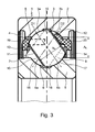
Figur 1 Figur 3- eine vergrößerte Darstellung der Einzelheit X des erfindungsgemäß ausgebildeten Kugelrollenlagers gemäß
Figur 2 Figur 4- eine vergrößerte Darstellung der beiden Kammkäfige des erfindungsgemäß ausgebildeten Kugelrollenlagers;
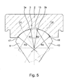
Figur 5- eine schematisierte Darstellung eines Querschnitts durch den äußeren Lagerring des erfindungsgemäß ausgebildeten Kugelrollenlagers mit anlaufenden Kugelrollen.
- FIG. 1
- an overall side view of an inventively designed ball roller bearing;
- FIG. 2
- the cross-section A - A through the inventively embodied ball roller bearing according to
FIG. 1 ; - FIG. 3
- an enlarged view of the detail X of the inventively designed ball roller bearing according to
FIG. 2 ; - FIG. 4
- an enlarged view of the two comb cages of the inventively designed ball roller bearing;
- FIG. 5
- a schematic representation of a cross section through the outer bearing ring of the inventively embodied ball roller bearing with incoming ball rollers.
Aus den
Um ein solches Kugelrollenlager 1 vor allem einfach und kostengünstig herstellen sowie mit geringem Aufwand zu einer transportfähigen Baueinheit montieren zu können, sind, wie insbesondere aus
Die
Ein weiteres kennzeichnendes Merkmal der Kammkäfige 19, 20 ist es, dass diese, wie in
Darüber hinaus ist in
Schließlich wird in
- 11
- KugelrollenlagerBall Roller Bearings
- 22
- äußerer Lagerringouter bearing ring
- 33
- Laufbahn in 4Career in 4
- 3a3a
- Laufbahnsegment von 3Career segment of 3
- 3b3b
- Laufbahnsegment von 3Career segment of 3
- 44
- Innenseite von 2Inside of 2
- 55
- innerer Lagerringinner bearing ring
- 66
- Laufbahn in 7Career in 7
- 6a6a
- Laufbahnsegment von 7Career segment of 7
- 6b6b
- Laufbahnsegment von 7Career segment of 7
- 77
- Außenseite von 5Outside of 5
- 88th
- Lagerkäfigbearing cage
- 99
- Kugelrollenball rolling
- 1010
- Kugelrollenball rolling
- 1111
- Seitenfläche von 10Side area of 10
- 1212
- Seitenfläche von 10Side area of 10
- 1313
- Seitenfläche von 11Side surface of 11
- 1414
- Seitenfläche von 11Side surface of 11
- 1515
- Ringnut in 3Ring groove in 3
- 1616
- Ringnut in 6Ring groove in 6
- 1717
- Lauffläche von 9Tread of 9
- 1818
- Lauffläche von 10Tread of 10
- 1919
- Kammkäfig für 9Comb cage for 9
- 2020
- Kammkäfig für 10Comb cage for 10
- 2121
- Käfigtaschen in 19Cage pockets in 19
- 2222
- Käfigtaschen in 20Cage pockets in 20
- 2323
- radialer Profilschenkel von 19radial profile leg of 19
- 2424
- radialer Profilschenkel von 20radial profile leg of 20
- 2525
- axialer Profilschenkel von 19axial profile leg of 19
- 2626
- axialer Profilschenkel von 20axial profile leg of 20
- 2727
- Taschenboden von 21Pocket bottom of 21
- 2828
- Taschenboden von 22Pocket bottom of 22
- 2929
- Schräge an 27Sloping at 27
- 3030
- Schräge an 28Sloping at 28
- 3131
- Laschen an 19Tabs on 19
- 3232
- Laschen an 20Tabs on 20
- AL A L
- Radialabstand zwischen 2 und 5Radial distance between 2 and 5
- BK B K
- Breite von 9 und 10Width of 9 and 10
- D1D1
- Druckwinkelachse von 9Pressure angle axis of 9
- D2D2
- Druckwinkelachse von 10Print angle axis of 10
- R1R1
- Radius von 17Radius of 17
- R2R2
- Radius von 18Radius of 18
- R3R3
- Radius von 3aRadius of 3a
- R4R4
- Radius von 3bRadius of 3b
Claims (7)
- Ball roller bearing (1), in particular for accommodating combined radial and axial loads, composed substantially of an outer bearing ring (2) with a channel-shaped raceway (3) on the inner side (4) thereof, and of an inner bearing ring (5) with a channel-shaped raceway (6) on the outer side (7) thereof, and of a multiplicity of ball rollers (9, 10), which ball rollers roll between said bearing rings (2, 5) in the raceways (3, 6) and which ball rollers are held with uniform spacings to one another in the circumferential direction by a bearing cage (8) and which ball rollers have in each case two side surfaces (11, 12, 13, 14), which side surfaces are flattened symmetrically proceeding from a spherical basic shape and are arranged parallel to one another, and which ball rollers also have a width (BK) between said side surfaces (11, 12, 13, 14), which width is dimensioned to be larger than the radial spacing (AL) between the inner side (4) and the outer side (7) of the bearing rings (2, 5), wherein the raceways (3, 6) in the two bearing rings (2, 5) are divided by in each case one axially centrally encircling annular groove (15, 16) into in each case two raceway segments (3a, 3b and 6a, 6b), and in each case two ball rollers (9, 10) which are adjacent to one another are arranged with alternately crossing contact angle axes (D1, D2) between the bearing rings (2, 5), such that a first ball roller (9) rolls with its running surface (17) on two first diagonally opposite raceway segments (3a, 6b) and a second ball roller (10) rolls with its running surface (18) on two second diagonally opposite raceway segments (3b, 6a) of the inner and outer bearing rings (2, 5), characterized in that both the outer bearing ring (2) and the inner bearing ring (5) are formed as unipartite components, the ball roller bearing (1) is filled with the ball rollers (9, 10) according to the axial-tilt eccentric assembly process, which is known per se, through the radial spacing (AL) between the bearing rings (2, 5), and the bearing cage (8) is formed by two structurally identical comb-type cages (19, 20) which act independently of each other and which can likewise be inserted into the ball roller bearing (1) through the radial spacing (AL) between the bearing rings (2, 5).
- Ball roller bearing (1) according to Claim 1, characterized in that all of the first ball rollers (9), which are inclined with their contact angle axes (D1) in one direction, are guided in corresponding cage pockets (21) of one comb-type cage (19), and all of the second ball rollers (10), which are inclined with their contact angle axes (D2) in the other direction, are guided in corresponding cage pockets (22) of the other comb-type cage (20).
- Ball roller bearing (1) according to Claim 2, characterized in that the comb-type cages (19, 20) each have a rectangular profile cross section with an outer profiled limb (23, 24) aligned radially toward the inner bearing ring (5) and with an inner profiled limb (25, 26) aligned axially into the bearing interior, in which profiled limbs are formed the cage pockets (21, 22) which are designed as semicircular recesses.
- Ball roller bearing (1) according to Claim 3, characterized in that the cage pockets (21, 22), at their lowest point, extend approximately as far as the radial profiled limb (23, 24) of each comb-type cage (19, 20), and the pocket base (27, 28) of each cage pocket (21, 22) is formed with a bevel (29, 30) matched to the inclination of the contact angle axis (D1, D2) of the ball roller (9, 10) to be held in said cage pocket (21, 22).
- Ball roller bearing (1) according to Claim 4, characterized in that the two comb-type cages (19, 20) have, between their cage pockets (21, 22), a plurality of lugs (31, 32) which are integrally formed on the radial profiled limbs (23, 24) of said comb-type cages and which project axially inward and radially obliquely outward from the axial profiled limbs (25, 26) of said comb-type cages, by means of which lugs the comb-type cages (19, 20) can be fixed in the ball roller bearing (1) by being latched into the raceway (3) of the outer bearing ring (2).
- Ball roller bearing (1) according to Claim 5, characterized in that, when the bearing is at a standstill, the ball rollers (9, 10), bearing in each case with an edge region of their running surfaces (17, 18) against the pocket bases (27, 28) of the cage pockets (21, 22) of one comb-type cage (19, 20) and with one of their side surfaces (12, 13) against the undersides of the lugs (31, 32) of the other comb-type cage (20, 19), can be fixed in a starting position corresponding to the inclination of the contact angle axes (D1, D2) of said ball rollers.
- Ball roller bearing (1) according to Claim 1, characterized in that the radii (R1, R2) of the running surfaces (17, 18) of the ball rollers (9, 10) are slightly smaller than the radii (R3, R4) of the raceway segments (3a, 3b, 6a, 6b) in the bearing rings (2, 5), such that the raceways (3, 6) of the two bearing rings (2, 5) have, overall, a gothic cross-sectional profile and the ball rollers (9, 10) roll with in each case only punctiform contact on the raceway segments (3a, 3b, 6a, 6b) of said bearing rings.
Applications Claiming Priority (2)
| Application Number | Priority Date | Filing Date | Title |
|---|---|---|---|
| DE102009014169A DE102009014169A1 (en) | 2009-03-20 | 2009-03-20 | Ball roller bearings, in particular for absorbing combined radial and axial loads |
| PCT/EP2010/053631 WO2010106174A1 (en) | 2009-03-20 | 2010-03-19 | Ball roller bearing, in particular for absorbing combined radial and axial loads |
Publications (2)
| Publication Number | Publication Date |
|---|---|
| EP2409045A1 EP2409045A1 (en) | 2012-01-25 |
| EP2409045B1 true EP2409045B1 (en) | 2013-01-23 |
Family
ID=42269762
Family Applications (1)
| Application Number | Title | Priority Date | Filing Date |
|---|---|---|---|
| EP10709542A Not-in-force EP2409045B1 (en) | 2009-03-20 | 2010-03-19 | Ball roller bearing, in particular for absorbing combined radial and axial loads |
Country Status (5)
| Country | Link |
|---|---|
| US (1) | US8690447B2 (en) |
| EP (1) | EP2409045B1 (en) |
| CN (1) | CN102362087B (en) |
| DE (1) | DE102009014169A1 (en) |
| WO (1) | WO2010106174A1 (en) |
Families Citing this family (8)
| Publication number | Priority date | Publication date | Assignee | Title |
|---|---|---|---|---|
| DE102011001736A1 (en) * | 2011-04-01 | 2012-10-04 | Zf Lenksysteme Gmbh | Bearing for use in steering of motor vehicle, has inner ring, outer ring and rolling body row with multiple rolling bodies, where rolling bodies are arranged behind one another in rolling body row |
| JP6084365B2 (en) | 2012-03-26 | 2017-02-22 | Ntn株式会社 | Cage and ball bearing |
| DE102012218409A1 (en) * | 2012-10-10 | 2014-04-24 | Schaeffler Technologies Gmbh & Co. Kg | Ball Roller Bearings |
| DE102014210751A1 (en) * | 2014-06-05 | 2015-12-17 | Schaeffler Technologies AG & Co. KG | Rolling bearings, in particular deep groove ball bearings, with guide aids for rolling elements |
| DE102014222094A1 (en) * | 2014-10-29 | 2016-05-04 | Aktiebolaget Skf | roller bearing |
| CN109557799B (en) * | 2017-09-25 | 2022-08-05 | 劳力士有限公司 | Clock bearing |
| CN108006086B (en) * | 2017-12-31 | 2023-09-15 | 无锡华洋滚动轴承有限公司 | Self-positioning equal-pressure assembling device |
| CN111546011A (en) * | 2020-05-16 | 2020-08-18 | 江苏德纳精工轴承有限公司 | Manufacturing and processing technology of outer ring crack type bearing |
Family Cites Families (12)
| Publication number | Priority date | Publication date | Assignee | Title |
|---|---|---|---|---|
| US1127133A (en) * | 1914-07-13 | 1915-02-02 | Standard Car Truck Co | Lateral-motion roller-bearing. |
| DE331455C (en) | 1919-04-12 | 1921-01-07 | Skf Svenska Kullagerfab Ab | Idler roller bearings |
| US1608892A (en) * | 1926-03-06 | 1926-11-30 | Andrew H Linde | Cage for ball bearings |
| DE10027105C2 (en) | 1999-05-31 | 2003-08-21 | Nsk Ltd | roller bearing |
| CN100340782C (en) * | 2002-01-11 | 2007-10-03 | 日本精工株式会社 | Rolling bearing |
| JP2006250200A (en) | 2005-03-09 | 2006-09-21 | Nsk Ltd | Rolling bearing |
| DE102005014556A1 (en) * | 2005-03-31 | 2006-10-05 | Schaeffler Kg | Radial rolling bearings, in particular single row deep groove ball bearings |
| DE102005059032A1 (en) * | 2005-12-10 | 2007-06-14 | Schaeffler Kg | Radial rolling bearings, in particular single-row grooved rolling bearings |
| DE102005061792A1 (en) * | 2005-12-23 | 2007-07-05 | Schaeffler Kg | Radial rolling bearing especially for vehicle transmissions has at least one axial flange defining grooved track between inner and outer bearing ring radially reduced height for fitting increased number of balls in axial assembly process |
| DE102006019228A1 (en) | 2006-04-26 | 2007-10-31 | Schaeffler Kg | Radial rolling bearing, in particular single row ball roller bearing, and method for its assembly |
| DE102006019230A1 (en) * | 2006-04-26 | 2007-10-31 | Schaeffler Kg | Radial rolling bearing, in particular single row ball roller bearing |
| DE102007062319A1 (en) | 2007-12-21 | 2009-06-25 | Schaeffler Kg | Method for filling a ball roller bearing with rolling elements and filled by the process ball roller bearing |
-
2009
- 2009-03-20 DE DE102009014169A patent/DE102009014169A1/en not_active Withdrawn
-
2010
- 2010-03-19 CN CN201080012967.1A patent/CN102362087B/en not_active Expired - Fee Related
- 2010-03-19 WO PCT/EP2010/053631 patent/WO2010106174A1/en active Application Filing
- 2010-03-19 EP EP10709542A patent/EP2409045B1/en not_active Not-in-force
- 2010-03-19 US US13/254,769 patent/US8690447B2/en not_active Expired - Fee Related
Also Published As
| Publication number | Publication date |
|---|---|
| CN102362087B (en) | 2014-04-23 |
| US20110311174A1 (en) | 2011-12-22 |
| EP2409045A1 (en) | 2012-01-25 |
| CN102362087A (en) | 2012-02-22 |
| US8690447B2 (en) | 2014-04-08 |
| DE102009014169A1 (en) | 2010-09-23 |
| WO2010106174A1 (en) | 2010-09-23 |
Similar Documents
| Publication | Publication Date | Title |
|---|---|---|
| EP2409045B1 (en) | Ball roller bearing, in particular for absorbing combined radial and axial loads | |
| DE19902565B4 (en) | Thrust washer of a planetary drive | |
| EP3332136B1 (en) | Method and device for producing an angular contact roller bearing | |
| DE102009040008A1 (en) | Cage for a rolling bearing and roller bearings | |
| DE102009021641A1 (en) | roller bearing | |
| EP2478235B1 (en) | Ball roller bearing | |
| WO2007065414A1 (en) | Radial antifriction bearing, especially single-row grooved antifriction bearing | |
| EP2013499B1 (en) | Radial anti friction bearing, in particular single-row spherical roller bearing, and method for mounting thereof | |
| DE102011014310A1 (en) | Crankshaft for reciprocating piston engine, comprises two main bearings, which are arranged symmetrical to rotational axis of crankshaft, connecting rod bearing, and crank arms for connecting main bearing and connecting rod bearing | |
| EP2434170A2 (en) | Bearing assembly | |
| EP3332137B1 (en) | Angular contact roller bearing and method and device for the assembly thereof | |
| EP3168496A1 (en) | Gearbox and method for producing such a gearbox | |
| DE102008029088A1 (en) | Bottom bracket bearing unit for bicycle, has common outer race with two axially spaced circumferential recesses and two axially spaced circumferential projections that are arranged rotationally symmetric to rotational axis of outer race | |
| EP2884128A1 (en) | Cage for a rolling bearing, and roller bearing with a cage | |
| DE2014420B2 (en) | Snap fit roller bearing cage - has pocket finger projections formed into radial lubricant grooves in pocket wall centres | |
| DE102014219705B4 (en) | bearing ring | |
| DE102009031793A1 (en) | Drive arrangement for a continuously variable transmission of a motor vehicle | |
| DE102016201100B4 (en) | Slide bearing ring and actuator with plain bearing ring | |
| DE102006051643B4 (en) | Tandem angular contact bearings | |
| EP2906842B1 (en) | Ball roller bearing | |
| EP3168497A1 (en) | Gearbox and the use of a gearbox | |
| DE2338687A1 (en) | CABLE-LESS ROLLER BEARING WITH PRE-LOADED HOLLOW ROLLERS | |
| DE102018100392B3 (en) | Axial needle bearing and method for producing a running disk of such an axial needle bearing | |
| DE102009031077A1 (en) | Completely rolling- radial ball bearing is provided with outer bearing ring and inner bearing ring, where multiple ball bearings are provided, which have two side surfaces | |
| DE102010009330A1 (en) | Skew-angle roller bearing i.e. multi-row skew-angle roller bearing, for use with main spindle of machine tool for high speed machine cutting, has rolling members with no or small rotating movements in direction of travel in load-free zone |
Legal Events
| Date | Code | Title | Description |
|---|---|---|---|
| PUAI | Public reference made under article 153(3) epc to a published international application that has entered the european phase |
Free format text: ORIGINAL CODE: 0009012 |
|
| 17P | Request for examination filed |
Effective date: 20111020 |
|
| AK | Designated contracting states |
Kind code of ref document: A1 Designated state(s): AT BE BG CH CY CZ DE DK EE ES FI FR GB GR HR HU IE IS IT LI LT LU LV MC MK MT NL NO PL PT RO SE SI SK SM TR |
|
| RAP1 | Party data changed (applicant data changed or rights of an application transferred) |
Owner name: SCHAEFFLER TECHNOLOGIES AG & CO. KG |
|
| DAX | Request for extension of the european patent (deleted) | ||
| GRAP | Despatch of communication of intention to grant a patent |
Free format text: ORIGINAL CODE: EPIDOSNIGR1 |
|
| GRAS | Grant fee paid |
Free format text: ORIGINAL CODE: EPIDOSNIGR3 |
|
| GRAA | (expected) grant |
Free format text: ORIGINAL CODE: 0009210 |
|
| AK | Designated contracting states |
Kind code of ref document: B1 Designated state(s): AT BE BG CH CY CZ DE DK EE ES FI FR GB GR HR HU IE IS IT LI LT LU LV MC MK MT NL NO PL PT RO SE SI SK SM TR |
|
| REG | Reference to a national code |
Ref country code: GB Ref legal event code: FG4D Free format text: NOT ENGLISH |
|
| REG | Reference to a national code |
Ref country code: CH Ref legal event code: EP |
|
| REG | Reference to a national code |
Ref country code: AT Ref legal event code: REF Ref document number: 595136 Country of ref document: AT Kind code of ref document: T Effective date: 20130215 Ref country code: CH Ref legal event code: EP |
|
| REG | Reference to a national code |
Ref country code: IE Ref legal event code: FG4D Free format text: LANGUAGE OF EP DOCUMENT: GERMAN |
|
| REG | Reference to a national code |
Ref country code: DE Ref legal event code: R096 Ref document number: 502010002208 Country of ref document: DE Effective date: 20130321 |
|
| REG | Reference to a national code |
Ref country code: LT Ref legal event code: MG4D |
|
| REG | Reference to a national code |
Ref country code: NL Ref legal event code: VDEP Effective date: 20130123 |
|
| PG25 | Lapsed in a contracting state [announced via postgrant information from national office to epo] |
Ref country code: SE Free format text: LAPSE BECAUSE OF FAILURE TO SUBMIT A TRANSLATION OF THE DESCRIPTION OR TO PAY THE FEE WITHIN THE PRESCRIBED TIME-LIMIT Effective date: 20130123 Ref country code: IS Free format text: LAPSE BECAUSE OF FAILURE TO SUBMIT A TRANSLATION OF THE DESCRIPTION OR TO PAY THE FEE WITHIN THE PRESCRIBED TIME-LIMIT Effective date: 20130523 Ref country code: NO Free format text: LAPSE BECAUSE OF FAILURE TO SUBMIT A TRANSLATION OF THE DESCRIPTION OR TO PAY THE FEE WITHIN THE PRESCRIBED TIME-LIMIT Effective date: 20130423 Ref country code: BG Free format text: LAPSE BECAUSE OF FAILURE TO SUBMIT A TRANSLATION OF THE DESCRIPTION OR TO PAY THE FEE WITHIN THE PRESCRIBED TIME-LIMIT Effective date: 20130423 Ref country code: ES Free format text: LAPSE BECAUSE OF FAILURE TO SUBMIT A TRANSLATION OF THE DESCRIPTION OR TO PAY THE FEE WITHIN THE PRESCRIBED TIME-LIMIT Effective date: 20130504 Ref country code: LT Free format text: LAPSE BECAUSE OF FAILURE TO SUBMIT A TRANSLATION OF THE DESCRIPTION OR TO PAY THE FEE WITHIN THE PRESCRIBED TIME-LIMIT Effective date: 20130123 |
|
| PG25 | Lapsed in a contracting state [announced via postgrant information from national office to epo] |
Ref country code: LV Free format text: LAPSE BECAUSE OF FAILURE TO SUBMIT A TRANSLATION OF THE DESCRIPTION OR TO PAY THE FEE WITHIN THE PRESCRIBED TIME-LIMIT Effective date: 20130123 Ref country code: FI Free format text: LAPSE BECAUSE OF FAILURE TO SUBMIT A TRANSLATION OF THE DESCRIPTION OR TO PAY THE FEE WITHIN THE PRESCRIBED TIME-LIMIT Effective date: 20130123 Ref country code: PL Free format text: LAPSE BECAUSE OF FAILURE TO SUBMIT A TRANSLATION OF THE DESCRIPTION OR TO PAY THE FEE WITHIN THE PRESCRIBED TIME-LIMIT Effective date: 20130123 Ref country code: SI Free format text: LAPSE BECAUSE OF FAILURE TO SUBMIT A TRANSLATION OF THE DESCRIPTION OR TO PAY THE FEE WITHIN THE PRESCRIBED TIME-LIMIT Effective date: 20130123 Ref country code: GR Free format text: LAPSE BECAUSE OF FAILURE TO SUBMIT A TRANSLATION OF THE DESCRIPTION OR TO PAY THE FEE WITHIN THE PRESCRIBED TIME-LIMIT Effective date: 20130424 Ref country code: PT Free format text: LAPSE BECAUSE OF FAILURE TO SUBMIT A TRANSLATION OF THE DESCRIPTION OR TO PAY THE FEE WITHIN THE PRESCRIBED TIME-LIMIT Effective date: 20130523 Ref country code: NL Free format text: LAPSE BECAUSE OF FAILURE TO SUBMIT A TRANSLATION OF THE DESCRIPTION OR TO PAY THE FEE WITHIN THE PRESCRIBED TIME-LIMIT Effective date: 20130123 |
|
| BERE | Be: lapsed |
Owner name: SCHAEFFLER TECHNOLOGIES A.G. & CO. KG Effective date: 20130331 |
|
| PG25 | Lapsed in a contracting state [announced via postgrant information from national office to epo] |
Ref country code: HR Free format text: LAPSE BECAUSE OF FAILURE TO SUBMIT A TRANSLATION OF THE DESCRIPTION OR TO PAY THE FEE WITHIN THE PRESCRIBED TIME-LIMIT Effective date: 20130123 |
|
| PG25 | Lapsed in a contracting state [announced via postgrant information from national office to epo] |
Ref country code: CZ Free format text: LAPSE BECAUSE OF FAILURE TO SUBMIT A TRANSLATION OF THE DESCRIPTION OR TO PAY THE FEE WITHIN THE PRESCRIBED TIME-LIMIT Effective date: 20130123 Ref country code: RO Free format text: LAPSE BECAUSE OF FAILURE TO SUBMIT A TRANSLATION OF THE DESCRIPTION OR TO PAY THE FEE WITHIN THE PRESCRIBED TIME-LIMIT Effective date: 20130123 Ref country code: MC Free format text: LAPSE BECAUSE OF NON-PAYMENT OF DUE FEES Effective date: 20130331 Ref country code: DK Free format text: LAPSE BECAUSE OF FAILURE TO SUBMIT A TRANSLATION OF THE DESCRIPTION OR TO PAY THE FEE WITHIN THE PRESCRIBED TIME-LIMIT Effective date: 20130123 Ref country code: EE Free format text: LAPSE BECAUSE OF FAILURE TO SUBMIT A TRANSLATION OF THE DESCRIPTION OR TO PAY THE FEE WITHIN THE PRESCRIBED TIME-LIMIT Effective date: 20130123 Ref country code: SK Free format text: LAPSE BECAUSE OF FAILURE TO SUBMIT A TRANSLATION OF THE DESCRIPTION OR TO PAY THE FEE WITHIN THE PRESCRIBED TIME-LIMIT Effective date: 20130123 |
|
| PG25 | Lapsed in a contracting state [announced via postgrant information from national office to epo] |
Ref country code: CY Free format text: LAPSE BECAUSE OF FAILURE TO SUBMIT A TRANSLATION OF THE DESCRIPTION OR TO PAY THE FEE WITHIN THE PRESCRIBED TIME-LIMIT Effective date: 20130123 |
|
| PLBE | No opposition filed within time limit |
Free format text: ORIGINAL CODE: 0009261 |
|
| STAA | Information on the status of an ep patent application or granted ep patent |
Free format text: STATUS: NO OPPOSITION FILED WITHIN TIME LIMIT |
|
| 26N | No opposition filed |
Effective date: 20131024 |
|
| REG | Reference to a national code |
Ref country code: IE Ref legal event code: MM4A |
|
| PG25 | Lapsed in a contracting state [announced via postgrant information from national office to epo] |
Ref country code: BE Free format text: LAPSE BECAUSE OF NON-PAYMENT OF DUE FEES Effective date: 20130331 Ref country code: IE Free format text: LAPSE BECAUSE OF NON-PAYMENT OF DUE FEES Effective date: 20130319 |
|
| REG | Reference to a national code |
Ref country code: DE Ref legal event code: R097 Ref document number: 502010002208 Country of ref document: DE Effective date: 20131024 |
|
| REG | Reference to a national code |
Ref country code: DE Ref legal event code: R081 Ref document number: 502010002208 Country of ref document: DE Owner name: SCHAEFFLER TECHNOLOGIES AG & CO. KG, DE Free format text: FORMER OWNER: SCHAEFFLER TECHNOLOGIES AG & CO. KG, 91074 HERZOGENAURACH, DE Effective date: 20140218 Ref country code: DE Ref legal event code: R081 Ref document number: 502010002208 Country of ref document: DE Owner name: SCHAEFFLER TECHNOLOGIES GMBH & CO. KG, DE Free format text: FORMER OWNER: SCHAEFFLER TECHNOLOGIES AG & CO. KG, 91074 HERZOGENAURACH, DE Effective date: 20140218 |
|
| PG25 | Lapsed in a contracting state [announced via postgrant information from national office to epo] |
Ref country code: MT Free format text: LAPSE BECAUSE OF FAILURE TO SUBMIT A TRANSLATION OF THE DESCRIPTION OR TO PAY THE FEE WITHIN THE PRESCRIBED TIME-LIMIT Effective date: 20130123 |
|
| REG | Reference to a national code |
Ref country code: CH Ref legal event code: PL |
|
| GBPC | Gb: european patent ceased through non-payment of renewal fee |
Effective date: 20140319 |
|
| PG25 | Lapsed in a contracting state [announced via postgrant information from national office to epo] |
Ref country code: LI Free format text: LAPSE BECAUSE OF NON-PAYMENT OF DUE FEES Effective date: 20140331 Ref country code: GB Free format text: LAPSE BECAUSE OF NON-PAYMENT OF DUE FEES Effective date: 20140319 Ref country code: CH Free format text: LAPSE BECAUSE OF NON-PAYMENT OF DUE FEES Effective date: 20140331 |
|
| REG | Reference to a national code |
Ref country code: FR Ref legal event code: PLFP Year of fee payment: 6 |
|
| PGFP | Annual fee paid to national office [announced via postgrant information from national office to epo] |
Ref country code: IT Payment date: 20150326 Year of fee payment: 6 |
|
| REG | Reference to a national code |
Ref country code: DE Ref legal event code: R081 Ref document number: 502010002208 Country of ref document: DE Owner name: SCHAEFFLER TECHNOLOGIES AG & CO. KG, DE Free format text: FORMER OWNER: SCHAEFFLER TECHNOLOGIES GMBH & CO. KG, 91074 HERZOGENAURACH, DE Effective date: 20150407 |
|
| PG25 | Lapsed in a contracting state [announced via postgrant information from national office to epo] |
Ref country code: SM Free format text: LAPSE BECAUSE OF FAILURE TO SUBMIT A TRANSLATION OF THE DESCRIPTION OR TO PAY THE FEE WITHIN THE PRESCRIBED TIME-LIMIT Effective date: 20130123 |
|
| PG25 | Lapsed in a contracting state [announced via postgrant information from national office to epo] |
Ref country code: TR Free format text: LAPSE BECAUSE OF FAILURE TO SUBMIT A TRANSLATION OF THE DESCRIPTION OR TO PAY THE FEE WITHIN THE PRESCRIBED TIME-LIMIT Effective date: 20130123 |
|
| PG25 | Lapsed in a contracting state [announced via postgrant information from national office to epo] |
Ref country code: LU Free format text: LAPSE BECAUSE OF NON-PAYMENT OF DUE FEES Effective date: 20130319 Ref country code: HU Free format text: LAPSE BECAUSE OF FAILURE TO SUBMIT A TRANSLATION OF THE DESCRIPTION OR TO PAY THE FEE WITHIN THE PRESCRIBED TIME-LIMIT; INVALID AB INITIO Effective date: 20100319 Ref country code: MK Free format text: LAPSE BECAUSE OF FAILURE TO SUBMIT A TRANSLATION OF THE DESCRIPTION OR TO PAY THE FEE WITHIN THE PRESCRIBED TIME-LIMIT Effective date: 20130123 |
|
| PGFP | Annual fee paid to national office [announced via postgrant information from national office to epo] |
Ref country code: DE Payment date: 20150601 Year of fee payment: 6 |
|
| PGFP | Annual fee paid to national office [announced via postgrant information from national office to epo] |
Ref country code: FR Payment date: 20150331 Year of fee payment: 6 |
|
| REG | Reference to a national code |
Ref country code: AT Ref legal event code: MM01 Ref document number: 595136 Country of ref document: AT Kind code of ref document: T Effective date: 20150319 |
|
| PG25 | Lapsed in a contracting state [announced via postgrant information from national office to epo] |
Ref country code: AT Free format text: LAPSE BECAUSE OF NON-PAYMENT OF DUE FEES Effective date: 20150319 |
|
| REG | Reference to a national code |
Ref country code: DE Ref legal event code: R119 Ref document number: 502010002208 Country of ref document: DE |
|
| REG | Reference to a national code |
Ref country code: FR Ref legal event code: ST Effective date: 20161130 |
|
| PG25 | Lapsed in a contracting state [announced via postgrant information from national office to epo] |
Ref country code: DE Free format text: LAPSE BECAUSE OF NON-PAYMENT OF DUE FEES Effective date: 20161001 Ref country code: FR Free format text: LAPSE BECAUSE OF NON-PAYMENT OF DUE FEES Effective date: 20160331 |
|
| PG25 | Lapsed in a contracting state [announced via postgrant information from national office to epo] |
Ref country code: IT Free format text: LAPSE BECAUSE OF NON-PAYMENT OF DUE FEES Effective date: 20160319 |