EP2409024B1 - Ensemble turbine - Google Patents
Ensemble turbine Download PDFInfo
- Publication number
- EP2409024B1 EP2409024B1 EP10723245A EP10723245A EP2409024B1 EP 2409024 B1 EP2409024 B1 EP 2409024B1 EP 10723245 A EP10723245 A EP 10723245A EP 10723245 A EP10723245 A EP 10723245A EP 2409024 B1 EP2409024 B1 EP 2409024B1
- Authority
- EP
- European Patent Office
- Prior art keywords
- rotor
- shroud
- axis
- turbine assembly
- rotation
- Prior art date
- Legal status (The legal status is an assumption and is not a legal conclusion. Google has not performed a legal analysis and makes no representation as to the accuracy of the status listed.)
- Active
Links
- 238000000034 method Methods 0.000 claims description 12
- 238000009434 installation Methods 0.000 description 28
- 230000000712 assembly Effects 0.000 description 14
- 238000000429 assembly Methods 0.000 description 14
- 230000008901 benefit Effects 0.000 description 12
- 230000033001 locomotion Effects 0.000 description 11
- 238000011144 upstream manufacturing Methods 0.000 description 11
- 238000010276 construction Methods 0.000 description 8
- 230000004044 response Effects 0.000 description 8
- 230000005611 electricity Effects 0.000 description 5
- 230000036961 partial effect Effects 0.000 description 5
- 230000007613 environmental effect Effects 0.000 description 4
- 230000002829 reductive effect Effects 0.000 description 4
- 230000005540 biological transmission Effects 0.000 description 3
- 238000009826 distribution Methods 0.000 description 3
- 238000012423 maintenance Methods 0.000 description 3
- 230000004323 axial length Effects 0.000 description 2
- 230000008859 change Effects 0.000 description 2
- 230000001419 dependent effect Effects 0.000 description 2
- 230000000694 effects Effects 0.000 description 2
- 231100001261 hazardous Toxicity 0.000 description 2
- 238000004519 manufacturing process Methods 0.000 description 2
- 239000007787 solid Substances 0.000 description 2
- OKTJSMMVPCPJKN-UHFFFAOYSA-N Carbon Chemical compound [C] OKTJSMMVPCPJKN-UHFFFAOYSA-N 0.000 description 1
- 241001465754 Metazoa Species 0.000 description 1
- 230000002411 adverse Effects 0.000 description 1
- 230000002547 anomalous effect Effects 0.000 description 1
- 230000015572 biosynthetic process Effects 0.000 description 1
- 229910052799 carbon Inorganic materials 0.000 description 1
- 230000008878 coupling Effects 0.000 description 1
- 238000010168 coupling process Methods 0.000 description 1
- 238000005859 coupling reaction Methods 0.000 description 1
- 239000012530 fluid Substances 0.000 description 1
- 239000002803 fossil fuel Substances 0.000 description 1
- 230000000670 limiting effect Effects 0.000 description 1
- 230000007246 mechanism Effects 0.000 description 1
- 238000010248 power generation Methods 0.000 description 1
- 230000001105 regulatory effect Effects 0.000 description 1
- 230000008439 repair process Effects 0.000 description 1
- 230000002441 reversible effect Effects 0.000 description 1
- 230000003068 static effect Effects 0.000 description 1
- 238000003860 storage Methods 0.000 description 1
- 230000000007 visual effect Effects 0.000 description 1
- 238000010792 warming Methods 0.000 description 1
- XLYOFNOQVPJJNP-UHFFFAOYSA-N water Substances O XLYOFNOQVPJJNP-UHFFFAOYSA-N 0.000 description 1
Images


Classifications
-
- F—MECHANICAL ENGINEERING; LIGHTING; HEATING; WEAPONS; BLASTING
- F03—MACHINES OR ENGINES FOR LIQUIDS; WIND, SPRING, OR WEIGHT MOTORS; PRODUCING MECHANICAL POWER OR A REACTIVE PROPULSIVE THRUST, NOT OTHERWISE PROVIDED FOR
- F03D—WIND MOTORS
- F03D3/00—Wind motors with rotation axis substantially perpendicular to the air flow entering the rotor
- F03D3/002—Wind motors with rotation axis substantially perpendicular to the air flow entering the rotor the axis being horizontal
-
- F—MECHANICAL ENGINEERING; LIGHTING; HEATING; WEAPONS; BLASTING
- F03—MACHINES OR ENGINES FOR LIQUIDS; WIND, SPRING, OR WEIGHT MOTORS; PRODUCING MECHANICAL POWER OR A REACTIVE PROPULSIVE THRUST, NOT OTHERWISE PROVIDED FOR
- F03D—WIND MOTORS
- F03D3/00—Wind motors with rotation axis substantially perpendicular to the air flow entering the rotor
- F03D3/04—Wind motors with rotation axis substantially perpendicular to the air flow entering the rotor having stationary wind-guiding means, e.g. with shrouds or channels
- F03D3/0436—Wind motors with rotation axis substantially perpendicular to the air flow entering the rotor having stationary wind-guiding means, e.g. with shrouds or channels for shielding one side of the rotor
- F03D3/0472—Wind motors with rotation axis substantially perpendicular to the air flow entering the rotor having stationary wind-guiding means, e.g. with shrouds or channels for shielding one side of the rotor the shield orientation being adaptable to the wind motor
- F03D3/0481—Wind motors with rotation axis substantially perpendicular to the air flow entering the rotor having stationary wind-guiding means, e.g. with shrouds or channels for shielding one side of the rotor the shield orientation being adaptable to the wind motor and only with concentrating action, i.e. only increasing the airflow speed into the rotor, e.g. divergent outlets
-
- F—MECHANICAL ENGINEERING; LIGHTING; HEATING; WEAPONS; BLASTING
- F03—MACHINES OR ENGINES FOR LIQUIDS; WIND, SPRING, OR WEIGHT MOTORS; PRODUCING MECHANICAL POWER OR A REACTIVE PROPULSIVE THRUST, NOT OTHERWISE PROVIDED FOR
- F03D—WIND MOTORS
- F03D9/00—Adaptations of wind motors for special use; Combinations of wind motors with apparatus driven thereby; Wind motors specially adapted for installation in particular locations
- F03D9/007—Adaptations of wind motors for special use; Combinations of wind motors with apparatus driven thereby; Wind motors specially adapted for installation in particular locations the wind motor being combined with means for converting solar radiation into useful energy
-
- F—MECHANICAL ENGINEERING; LIGHTING; HEATING; WEAPONS; BLASTING
- F03—MACHINES OR ENGINES FOR LIQUIDS; WIND, SPRING, OR WEIGHT MOTORS; PRODUCING MECHANICAL POWER OR A REACTIVE PROPULSIVE THRUST, NOT OTHERWISE PROVIDED FOR
- F03D—WIND MOTORS
- F03D9/00—Adaptations of wind motors for special use; Combinations of wind motors with apparatus driven thereby; Wind motors specially adapted for installation in particular locations
- F03D9/20—Wind motors characterised by the driven apparatus
- F03D9/25—Wind motors characterised by the driven apparatus the apparatus being an electrical generator
-
- F—MECHANICAL ENGINEERING; LIGHTING; HEATING; WEAPONS; BLASTING
- F03—MACHINES OR ENGINES FOR LIQUIDS; WIND, SPRING, OR WEIGHT MOTORS; PRODUCING MECHANICAL POWER OR A REACTIVE PROPULSIVE THRUST, NOT OTHERWISE PROVIDED FOR
- F03D—WIND MOTORS
- F03D9/00—Adaptations of wind motors for special use; Combinations of wind motors with apparatus driven thereby; Wind motors specially adapted for installation in particular locations
- F03D9/30—Wind motors specially adapted for installation in particular locations
- F03D9/34—Wind motors specially adapted for installation in particular locations on stationary objects or on stationary man-made structures
-
- H—ELECTRICITY
- H02—GENERATION; CONVERSION OR DISTRIBUTION OF ELECTRIC POWER
- H02S—GENERATION OF ELECTRIC POWER BY CONVERSION OF INFRARED RADIATION, VISIBLE LIGHT OR ULTRAVIOLET LIGHT, e.g. USING PHOTOVOLTAIC [PV] MODULES
- H02S10/00—PV power plants; Combinations of PV energy systems with other systems for the generation of electric power
- H02S10/10—PV power plants; Combinations of PV energy systems with other systems for the generation of electric power including a supplementary source of electric power, e.g. hybrid diesel-PV energy systems
- H02S10/12—Hybrid wind-PV energy systems
-
- F—MECHANICAL ENGINEERING; LIGHTING; HEATING; WEAPONS; BLASTING
- F05—INDEXING SCHEMES RELATING TO ENGINES OR PUMPS IN VARIOUS SUBCLASSES OF CLASSES F01-F04
- F05B—INDEXING SCHEME RELATING TO WIND, SPRING, WEIGHT, INERTIA OR LIKE MOTORS, TO MACHINES OR ENGINES FOR LIQUIDS COVERED BY SUBCLASSES F03B, F03D AND F03G
- F05B2240/00—Components
- F05B2240/20—Rotors
- F05B2240/21—Rotors for wind turbines
- F05B2240/211—Rotors for wind turbines with vertical axis
- F05B2240/213—Rotors for wind turbines with vertical axis of the Savonius type
-
- F—MECHANICAL ENGINEERING; LIGHTING; HEATING; WEAPONS; BLASTING
- F05—INDEXING SCHEMES RELATING TO ENGINES OR PUMPS IN VARIOUS SUBCLASSES OF CLASSES F01-F04
- F05B—INDEXING SCHEME RELATING TO WIND, SPRING, WEIGHT, INERTIA OR LIKE MOTORS, TO MACHINES OR ENGINES FOR LIQUIDS COVERED BY SUBCLASSES F03B, F03D AND F03G
- F05B2240/00—Components
- F05B2240/90—Mounting on supporting structures or systems
- F05B2240/91—Mounting on supporting structures or systems on a stationary structure
- F05B2240/911—Mounting on supporting structures or systems on a stationary structure already existing for a prior purpose
-
- Y—GENERAL TAGGING OF NEW TECHNOLOGICAL DEVELOPMENTS; GENERAL TAGGING OF CROSS-SECTIONAL TECHNOLOGIES SPANNING OVER SEVERAL SECTIONS OF THE IPC; TECHNICAL SUBJECTS COVERED BY FORMER USPC CROSS-REFERENCE ART COLLECTIONS [XRACs] AND DIGESTS
- Y02—TECHNOLOGIES OR APPLICATIONS FOR MITIGATION OR ADAPTATION AGAINST CLIMATE CHANGE
- Y02B—CLIMATE CHANGE MITIGATION TECHNOLOGIES RELATED TO BUILDINGS, e.g. HOUSING, HOUSE APPLIANCES OR RELATED END-USER APPLICATIONS
- Y02B10/00—Integration of renewable energy sources in buildings
- Y02B10/30—Wind power
-
- Y—GENERAL TAGGING OF NEW TECHNOLOGICAL DEVELOPMENTS; GENERAL TAGGING OF CROSS-SECTIONAL TECHNOLOGIES SPANNING OVER SEVERAL SECTIONS OF THE IPC; TECHNICAL SUBJECTS COVERED BY FORMER USPC CROSS-REFERENCE ART COLLECTIONS [XRACs] AND DIGESTS
- Y02—TECHNOLOGIES OR APPLICATIONS FOR MITIGATION OR ADAPTATION AGAINST CLIMATE CHANGE
- Y02E—REDUCTION OF GREENHOUSE GAS [GHG] EMISSIONS, RELATED TO ENERGY GENERATION, TRANSMISSION OR DISTRIBUTION
- Y02E10/00—Energy generation through renewable energy sources
- Y02E10/50—Photovoltaic [PV] energy
-
- Y—GENERAL TAGGING OF NEW TECHNOLOGICAL DEVELOPMENTS; GENERAL TAGGING OF CROSS-SECTIONAL TECHNOLOGIES SPANNING OVER SEVERAL SECTIONS OF THE IPC; TECHNICAL SUBJECTS COVERED BY FORMER USPC CROSS-REFERENCE ART COLLECTIONS [XRACs] AND DIGESTS
- Y02—TECHNOLOGIES OR APPLICATIONS FOR MITIGATION OR ADAPTATION AGAINST CLIMATE CHANGE
- Y02E—REDUCTION OF GREENHOUSE GAS [GHG] EMISSIONS, RELATED TO ENERGY GENERATION, TRANSMISSION OR DISTRIBUTION
- Y02E10/00—Energy generation through renewable energy sources
- Y02E10/70—Wind energy
- Y02E10/728—Onshore wind turbines
-
- Y—GENERAL TAGGING OF NEW TECHNOLOGICAL DEVELOPMENTS; GENERAL TAGGING OF CROSS-SECTIONAL TECHNOLOGIES SPANNING OVER SEVERAL SECTIONS OF THE IPC; TECHNICAL SUBJECTS COVERED BY FORMER USPC CROSS-REFERENCE ART COLLECTIONS [XRACs] AND DIGESTS
- Y02—TECHNOLOGIES OR APPLICATIONS FOR MITIGATION OR ADAPTATION AGAINST CLIMATE CHANGE
- Y02E—REDUCTION OF GREENHOUSE GAS [GHG] EMISSIONS, RELATED TO ENERGY GENERATION, TRANSMISSION OR DISTRIBUTION
- Y02E10/00—Energy generation through renewable energy sources
- Y02E10/70—Wind energy
- Y02E10/74—Wind turbines with rotation axis perpendicular to the wind direction
Definitions
- the invention relates to a turbine assembly and particularly a turbine assembly having a shroud.
- Wind turbines offer domestic and commercial consumers the possibility of using wind energy for at least some of their energy requirements.
- WO 2005/052362 There are however several problems with such conventional wind turbines when used in the vicinity of buildings, structures or inhabited areas. For example it is necessary to use a large mast structure to support the turbine. Such supporting structures become increasingly large, costly and complex as the size of the turbine increases.
- an increase in energy demand above a certain level will require the installation of multiple turbines, further increasing the cost and complexity of the overall installation.
- Turbines of the type described above can be characterised as axial flow turbines. This means that, for efficient operation, they require a free stream air flow which is substantially parallel to their axis of rotation. This is achieved by rotating the turbine axis to face into the direction of the oncoming wind.
- a further problem with axial flow turbines is created by the rotor hub and associated generator assembly being located at a height above ground level of not less than the rotor radius plus the required blade tip clearance.
- the installation of the supporting mast together with the requirement to provide access to the rotor and associated generator components for maintenance and repair is both costly and difficult.
- Axial flow turbines are sometimes unsightly and are often objected to on these grounds. Early examples of axial flow turbines were often noisy, although more recent designs have resulted in quieter installations.
- Axial flow turbines also require rotor blades which have a complex geometry in order to achieve optimum aerodynamic efficiency.
- the manufacture of this type of blade is both expensive and difficult, becoming increasingly so as the rotor diameter increases.
- transverse flow turbine is that the swept area of the rotor can be increased by increasing either or both of the rotor diameter and the rotor length. This in turn provides more flexibility in designing a transverse flow turbine for any given output, for example the diameter of the turbine may be reduced whilst maintaining the cross section of the turbine by increasing its length.
- the transverse flow turbine is more practical for small scale power generation, particularly in built-up areas. For example, if an impulse rotor is incorporated into a transverse flow turbine, the turbine is more tolerant than an axial flow turbine to turbulent air flows, which are often found in built-up areas.
- transverse flow turbine lends itself to being mounted along the apex of the pitched roof of a structure. This form of installation has several advantages over the installation of axial flow turbines in a similar location.
- Transverse flow turbines are better suited to taking advantage of this increase in wind speed due to the shape of the air flow catchment area of the turbine.
- a transverse flow turbine when a transverse flow turbine is mounted above the apex of a pitched roof, it may be mounted close to the roof apex since the maximum wind speed will be in this region. Such an installation may be more easily installed and maintained and is therefore not subject to the structural constraints arising from the rotor and turbine hub being sited at the top of a tall mast.
- transverse flow turbine installation is less visually obtrusive and would be unlikely to suffer from objections due to unsightliness to the same extent as would an axial flow turbine.
- the transverse flow turbine installed in this manner exhibits a significantly lower "visual footprint" than an axial flow turbine of similar output.
- the lower blade tip velocities of the transverse flow turbine enable the turbine to have a lower noise signature.
- a transverse flow turbine is able to be sited on a wide range of buildings of varying sizes and orientations including domestic residences, business and industrial buildings and storage warehouses. It also lends itself to other applications including installation on temporary structures and vehicles and for installation along the roof edge or as a vertical axis turbine on the corner of a building or structure which would experience a similar rise in wind speed as that experienced on a roof apex installation.
- DE 102007032843 describes a wind generator turbine made of axial lamellae which are arranged in a gently sloping spiral with respect to the roller axis. Various arrangements are provided for directing wind across the wind generator roller.
- DE 19607592 describes a turbine consisting of a shaft and four or more turbine blades arranged radially. A half cover of the turbine is provided to prevent flow over the turbine in a counter direction, and the half cover is movable.
- a transverse flow wind turbine assembly comprising, a rotor having a plurality of blades, and a shroud comprising at least two shroud portions, extending axially along the rotor and around the rotor to at least partially enclose the rotor, there being at least two shroud portions rotationally adjustable in order to expose a portion of the rotor to the wind, and wherein the shroud, in use, defines a variable inlet and a variable outlet whereby, in use, the inlet area and outlet area are variable independently of each other in area and in angular position around the circumference of the turbine.
- shroud portions being determined and controlled by a shroud control device.
- the shroud portions can be positioned so as to cover that portion of the rotor in which the rotor blades are moving into the direction of the air stream and which would otherwise be reducing the efficiency of the turbine. This portion of the rotor is often termed the "dead sector"
- the shroud portions define an inlet and an outlet.
- the position of the shroud portions define an inlet and an outlet which represent respectively the area over which air enters the turbine assembly to impinge on the rotor, and the area over which the air is exhausted from the turbine assembly.
- the use of two or more shroud portions allows inlet and outlet areas to be independently or dependently variable in angular position and area whereby the inlet varies at a differing or variable amount to the outlet.
- the direction of movement and area change of the inlet may be in the same sense or the opposite sense to the outlet.
- a feature of the invention is that regardless of whether the inlet and outlet areas vary dependently or independently, adjustment of the inlet area or position does not result in the same magnitude of adjustment in area or position of the outlet in either the same or inverse sense.
- a person skilled in the art could envisage a number of ways of achieving independent variability of the inlet and outlet areas, for example by actuating two or more shroud portions separately.
- the inlet and outlet defined by the position of the shroud portions may be interchanged or any other adjustment made so as to direct airflows from the new direction.
- transverse flow turbines with rotatable substantially arc shaped shrouds are known in Patent Applications CA2387434A1 , DE2924970A1 , US6270308B1 , EP1930585A2 , DE3315439A1 .
- non of these articles feature the ability to vary inlet and outlet portions independently of each other or vary the inlet a different amount to the outlet.
- non of the prior articles allow an open sector to be varied by varying the upstream and downstream edges of the open area independently of each other or by varying the upstream edge a different amount to the downstream edge.
- shroud portions may block the air flow entering the rotor, for example when the turbine assembly is not in use or to protect it during hazardous environmental conditions.
- shroud portions The movement of shroud portions is controlled by the controller or control device in response to any number of inputs, for example in response to changes in wind speed, direction, temperature, pressure, humidity and vibration. This allows the turbine assembly to operate at optimum efficiency in varying conditions.
- one or more shroud portions could be self-controlling with movement of the shroud portion being controlled by aerodynamic forces acting on the blades and/or on the shroud itself.
- one or more shroud portions may be rotatable.
- the one or more shroud portions may be rotated about an axis which is co-axial with or is close to the axis of rotation of the rotor. This enables the degree of exposure of the rotor to the oncoming air stream to be varied from zero, where the rotor receives none of the oncoming flow, to full, where the complete rotor is exposed to the oncoming flow.
- the degree of exposure of the rotor to the oncoming flow can be controlled by the controller in response to changes in one or more parameters such as: wind speed; wind direction; temperature; pressure; humidity; vibration; and user requirements.
- the shroud portions may be positioned so as to completely enclose the rotor when the turbine assembly is not in use. This protects the turbine assembly from damage which, for example, might be caused by operation in hazardous environmental conditions. Where shroud portions do not have sufficient angular coverage to allow complete enclosure of the rotor, it may be possible to shroud the portion of the rotor exposed to the wind thereby achieving the same effect.
- the shroud may comprise between 2 and 4 shroud portions, although the shroud could have any number of shroud portions.
- An advantage of the shroud comprising a plurality of shroud portions is that it allows for more variation in the degree of shrouding provided to the rotor.
- each shroud portion is substantially arc shaped in cross section.
- Each shroud portion extends axially along the length of the rotor and includes a plate at each end. Each end plate connects the axial portion of the shroud portion to the axis of rotation of the shroud portion.
- the shroud portions are shaped so as to fit closely over the rotor, whilst still having sufficient clearance to rotate so as to expose a portion of the rotor.
- one or more shroud portions are spaced apart transversely from the axis of rotation of the rotor by a distance that is different to the distance by which the one or more other shroud portions are spaced apart transversely from the axis of rotation of the rotor.
- one or more shroud portions each have a radius that is different to the radius of each of the one or more other shroud portions.
- each shroud portion has a radius that is different from the radius of each other shroud portion forming the shroud.
- a shroud portion of a respective pair may have substantially the same spacing from the axis of rotation of the rotor as the other shroud portion of that pair, and the shroud portions of one pair may each have a different spacing from the axis of rotation of the rotor as the shroud portions of each other pair.
- the distance by which one or more shroud portions are spaced apart, transversely from the axis of rotation of the shroud portion varies with the angular position of the respective shroud portion relative to the axis of rotation of the shroud portion.
- the radius of a shroud portion relative to the axis of rotation of the shroud portion varies with the changing angular position of the shroud portion as it rotates about the axis of rotation of the shroud portion.
- only one shroud portion may have a radius that varies in this manner, whilst in other embodiments more than one shroud portion, or all shroud portions may have such a variable radius.
- the distance by which one or more shroud portions are spaced apart, transversely from the axis of rotation of the shroud portion varies with the angular position around the respective shroud portion.
- the radius at one edge of a shroud portion relative to the axis of rotation of the shroud portion is different to the radius at the other edge of the shroud portion (assuming an edge lies parallel to the axis of rotation of the shroud portion).
- a further advantage of these features is that they increase the angular range of motion of the shroud portions by enabling the partial overlap of two shroud portions which would not otherwise be possible if the respective shroud portions had substantially equal radii. This partial overlapping may result in the shroud portions abutting one another, the inner surface of one shroud portion abutting the outer surface of another shroud portion thus increasing the rigidity of the shroud portions.
- the axis of rotation of one or more shroud portions and the axis of rotation of the rotor are coaxial.
- shroud axis being coaxial with the rotor axis include simplification of both the construction of the turbine and the control of the movement of the shroud portions. This results from the shroud portions and the rotor having a common pivot point and control axis.
- the axis of rotation of one or more shroud portions are offset from the axis of rotation of the rotor.
- This feature provides for a variable clearance between the rotor blade tips and the inner surface of the shroud portions.
- the movement of the shroud portions can thus be configured to provide the optimal blade tip clearance around the periphery of the rotor.
- the axis of rotation of one or more shroud portions varies relative to the axis of rotation of the rotor as the one or more shroud portions rotate.
- the turbine assembly further comprises an actuator.
- the actuator may be operably connected to the controller.
- the actuator enables the position of one or more shroud portions to be varied in response to commands from the controller, for example in response to varying wind speed, direction, temperature, pressure, humidity and vibration.
- a plurality of actuators may be employed in order to be able to vary the position of each shroud portion independently of each other shroud portion. This enables the position of each of the plurality of shroud portions, relative to the rotor, to be independently varied depending upon environmental conditions and a user's requirements.
- one or more of the shroud portions includes an inlet guide extending axially along the shroud portion.
- the purpose of the inlet guide is firstly to direct incoming air flows in the plane of the rotor axis such that they impinge upon the rotor blade face at the optimum angle. Secondly, the inlet guide serves to increase the volume of air flow which is directed onto the rotor without unshrouding more of the rotor. Thirdly, the inlet guide serves to accelerate the air flow entering the turbine assembly by reducing the cross sectional area through which the air flow passes. Fourthly, the inlet guide serves to direct incoming cross wind air flows to a direction more normal to the axis of the rotor. Purposes of the inlet guide described above may be incorporated individually or in any combination.
- one or more of the shroud portions includes an exhaust guide extending axially along the shroud portion.
- the purpose of the exhaust guide is to provide optimal exhaust conditions by reducing the exhaust drag. This is achieved by lowering the air pressure immediately downstream of the exhaust by increasing the cross sectional area through which the flow passes.
- one or more shroud portions comprises a flow reversal device.
- the purpose of the flow reversal device is to reduce the angular extent of the dead sector of the turbine assembly.
- the flow reversal device enables blades otherwise located in the dead sector to extract energy from the flow.
- the flow reversal device may also increase the mass flow through the rotor.
- This increases the useful motive air flow into the inlet side of the turbine assembly. It also assists in changing the direction of this additional air flow so that it impinges on the rotor in such a way as to enable it to contribute positively to the useful work produced by the turbine assembly.
- one or more shroud portions includes a plurality of apertures.
- the apertures allow air to be drawn from inside the shroud into regions of low pressure above the top of the turbine assembly, and in the lee of the turbine assembly.
- the rotor further comprises a hub, each of the plurality of blades being attached to the hub.
- each of the blades projects perpendicularly from the hub, which further simplifies the construction of the rotor
- each of the blades may have a curved portion at their tip.
- the curved portions at the tips of the blades improve the efficiency of the rotor when used in air flows which are directed towards the concave side of the curved portion of the blade.
- the curved tips cause the blade to exhibit a different amount of drag on either side, the rotor will therefore rotate in one direction.
- the rotor may have two separate curved blades which are oriented so as to overlap at their inner edges.
- This rotor arrangement is commonly known as a Savonius geometry.
- the blades are not attached to the hub, since the rotor may constructed without a hub.
- the degree of curvature on each of the curved blades can be varied, for example with the innermost portion of each blade being substantially linear and each blade being positioned to provide a degree of overlap between the inner edges of the blades.
- the gap between the inner edges of the two blades is configured to allow a portion of the air flow impinging on one blade to "cross feed" to the opposite blade thus providing additional motive power to the rotor.
- the rotor may include between 2 and 20 blades, and preferably includes between 2 and 5 blades.
- each of the plurality of blades extends axially along a part of the hub, each blade adjoining the hub substantially parallel to the axis of rotation of the rotor.
- each of the plurality of blades extends along a part of the hub, each blade adjoining the hub in a helical path along the length of the rotor, the outermost edge of each blade forming a helix and the surface of each blade forming a helicoid.
- each blade By providing a turbine blade which extends helically around the hub, at least part of each blade is always positioned substantially perpendicularly to the oncoming air flow. In this way, the turbine may 'self start' from any angular start position (assuming that the rotor spiral twists through at least 360°/(number of blades)).
- a further advantage of the helical blade geometry is that the power output from the turbine is smoother because at least part of each blade is always exposed to the oncoming air flow (assuming that the rotor spiral twists through at least 360°/(number of blades)). This results in lower levels of noise and vibration when compared to a rotor having a parallel blade configuration.
- the degree of helical twist on the blade can be varied at the time of manufacture to provide a rotor performance which is optimised for a particular wind speed and direction.
- a rotor having a blade with a single helical geometry may be optimised for operation in cross winds from one end of the rotor.
- each of the plurality of blades extends along a part of the hub, each blade adjoining the hub in a path along the length of the rotor, the path being formed by a right handed helix originating at one end of the hub, and a left handed helix originating at the opposite end of the hub, the two opposing helical paths meeting between the ends of the hub, the outermost edge of each blade forming opposing helices and the surface of each blade forming opposing helicoids.
- one portion of the rotor may be optimised for operation in cross winds from one end of the rotor while the other portion of the rotor may be optimised for operation in cross winds from the opposite end of the rotor.
- the rotor blades may be offset from one another rather than being mounted on the hub.
- the blades may be offset from one another in a Savonius type geometry, for example, although the blades could have any suitable geometry.
- the rotor further includes a plurality of separator discs, each disc being located concentrically on the rotor, with the plane of each disc being normal to the axis of rotation of the rotor, each disc being spaced along the length of the rotor so as to divide the rotor into segments.
- the separator discs limit spanwise flows, which are air flows substantially along the direction of the axis of the rotor, and thus they allow energy to be transferred from the air stream to the rotor, equally across the span of the rotor and in the area where the air first impinged upon the blades.
- Separator disks may take the form of solid disks, perforated disks or partial disks.
- each rotor segment is offset by an angular increment from adjacent rotor segments.
- This feature provides for modular construction of the rotor making construction, assembly and maintenance easier.
- a linear blade geometry may be used to create a pseudo-helical rotor blade geometry which assists in providing a 'self starting' function to the turbine assembly.
- the turbine assembly further comprises a vibration sensor for measuring vibration of the turbine assembly.
- the vibration sensor can be used to provide an indication of the operational efficiency of the turbine assembly, and also to enable early warning of failure and damage.
- the vibration sensor detects an anomalous vibration, this may be an indication of a condition which might adversely affect the performance of the turbine assembly, for example, damage to a rotor blade or other part of the turbine assembly.
- a transverse flow wind turbine assembly comprising a rotor having a plurality of blades, and a shroud comprising at least two portions at least partially enclosing the rotor wherein at least two portions of the shroud are adjustable in order to expose a portion of the rotor to the wind, the rotor being connected to an electrical generator; the method comprising the steps of:
- the turbine assembly further comprising a plurality of sensors, each sensor being adapted to sense a variable
- the method comprises the additional initial steps of:
- the input which is received from the one or more sensors may be compared to either a preset value, or a previously measured value from one or more of the sensors, or a value determined from a "look-up"' table.
- the input received from the one or more sensors may be compared to an other predetermined value.
- variable is selected from the group comprising: wind speed; wind direction; temperature; humidity; vibration; and pressure.
- a roof for a building comprising a transverse flow wind turbine assembly according to the first aspect of the invention, the roof comprising an apex, the turbine assembly being positioned substantially parallel to the apex of the roof.
- the turbine would be mounted substantially above the apex of the roof, however the location may be to one side of the apex and thus as a result may be located at or below the height of the apex of the roof depending upon roof pitch angle and turbine diameter. In other embodiments the turbine may be located beneath the roof.
- a plurality of turbine assemblies according to the first aspect of the invention, the plurality of turbine assemblies installed in series along the apex of a roof, wherein the rotors of alternate turbine modules are contra-rotating, a generator coupled centrally between alternate modules, the rotor of one module driving the stator of the generator and the rotor of the adjacent module driving the rotor of the generator.
- the optional contra-rotating feature allows the possibility of turning the generator at a faster rotational speed by driving the stator and rotor of an electrical generator in opposite directions.
- each turbine assembly drives an electrical generator, the electrical outputs from each respective electrical generator being connected to a local electrical power distribution network, the electrical power generated by the turbine assemblies being supplied to local consumers in response to their electrical power requirements, in preference to the supply of electrical power from a remote generating site.
- electrical outputs from other devices using renewable energy such as photovoltaic cells, may be connected to the local electrical power distribution network.
- each of the turbine assemblies is mounted on a structure.
- the structures may be close to or adjacent to one another.
- a turbine assembly according to a first embodiment of the invention is designated generally by the reference numeral 10.
- the turbine assembly 10 comprises a rotor 20 having a plurality of blades 30, a hub 22, and a shroud 40.
- Each of the blades 30 is attached to the hub 22 and extends axially along the hub 22, forming a helical path along the length of the rotor 20.
- the outermost edge of each blade 30 forms a helix and the surface of each blade 30 forms a helicoid.
- the blades may have a different geometry.
- the turbine assembly 10 is preferably installed over the apex of a pitched roof of a structure, the rotor axis 94 being substantially parallel to the apex of the roof, the roof under the turbine assembly is omitted from Figures 1 to 4 .
- the shroud 40 is shaped so as to be capable of enclosing the rotor 20, and is rotatable so as to expose a portion of the rotor 20. In other embodiments the shroud 40 may not be capable of fully enclosing the rotor 20.
- the shroud 40 comprises four shroud portions 42, 44, 46, 48. In other embodiments of the invention, the shroud 40 may comprise a different number of shroud portions.
- movement of the shroud 40 is controlled by a controller or control device 72 in order to optimise the position of the shroud 40 depending upon the current wind speed and direction.
- the controller may take the form of an external controller, such as a computerised control system.
- the controller may take the form of a mechanism which utilises the aerodynamic forces acting on the rotor blades 30 and/or the shroud 40.
- the movement of the shroud 40 may also be controlled manually by an operator.
- Each shroud portion 42, 44, 46, 48 is formed so as to be substantially arc shaped in cross section, extending axially along the rotor 20 and circumferentially around a portion of the rotor blades 30.
- Each shroud portion 42, 44, 46, 48 includes, at each end, a substantially sector shaped end plate.
- the end plates may be circular or any other shape and they may include a counter balance.
- Each of the shroud portions 42, 44, 46, 48 is separately rotatable. However in other embodiments two or more shrouds may rotate together either in the same direction or in opposite directions, either by the same amount or a differential amount for example by using gears.
- Figure 2.1 is an exploded view of the turbine assembly of Figure 1 , illustrating the axis of rotation 94 of the rotor 20 and the axis of rotation 92 of one of the shroud portions 48, for simplicity the axis of rotation of the other shroud portions have been omitted.
- the axis of rotation 92 of each of the shroud portions 42, 44, 46, 48 is coaxial with the axis of rotation 94 of the rotor 20.
- shroud portions 42, 44, 46, 48 may have an axis of rotation 92 which is offset from the axis of rotation 94 of the rotor 20, for example by using a separate pivot point to achieve the required offset.
- the axis of rotation 92 of one or more of the shroud portions 42, 44, 46, 48 may vary as the shroud portion 42, 44, 46, 48 rotates, for example by the use of slotted guides or cams. This allows further optimisation of blade tip clearances and turbine shrouding.
- the shroud portions 42, 44, 46, 48 are arranged as a first pair of shroud portions 42, 46 and a second pair of shroud portions 44, 48.
- Each shroud portion of a respective pair has substantially the same spacing from the axis of rotation 94 of the rotor 20 as the other shroud portion of that pair.
- the first pair of shroud portions 42, 46 has a different spacing from the axis of rotation 94 of the rotor 20 than that of the second pair of shroud portions 44, 48.
- each of the first pair of shroud portions 42, 46 along the axis of rotation 94 of the rotor is different from the length of each of the second pair of shroud portions 44, 48 along the axis of rotation 94 of the rotor. This allows each of the first pair of shroud portions 42, 46 to be able to rotate past each of the second pair of shroud portion 44, 48, as shown in Figures 3 and 4 .
- each shroud portion 42, 44, 46, 48 is spaced apart 96, transversely from its axis of rotation 92 is constant. However, in other embodiments of the invention this distance 96 may vary with the angular position of the shroud portion 42, 44, 46, 48, relative to the axis of rotation 92 of the shroud portion 42, 44, 46, 48. Furthermore the distance by which each shroud portion 42, 44, 46, 48 is spaced apart 96, 97, 98, transversely from its axis of rotation 92 may be different at either edge of the shroud portion (assuming an edge lies parallel to the axis of rotation 92 of the shroud portion)
- One or more actuators 74 may be provided to vary the position of each of the shroud portions 42, 44, 46, 48 in response to signals from the controller 72. Each shroud portion 42, 44, 46, 48 is driven by a separate actuator 74. However, in other embodiments of the invention a single actuator 74 may drive more than one shroud portion 42, 44, 46, 48, or alternatively, more than one actuator 74 may drive one shroud portion 42, 44, 46, 48.
- the shroud portions 42, 44, 46, 48 are rotated so as to create an inlet 50 and an outlet 52 through which an air flow can pass. Since the shroud 40 comprises a plurality of shroud portions 42, 44, 46, 48, it is possible to position an inlet and outlet appropriately depending upon the wind speed and direction.
- the air flow passes over the rotor hub 22.
- the turbine assembly 10 is preferably installed over the apex of a pitched roof of a structure, the rotor axis 94 being substantially parallel to the apex of the roof, the roof under the turbine assembly is omitted from this figure.
- inlet 50 and outlet 52 areas allow inlet 50 and outlet 52 areas to be independently or dependently variable in angular position and area whereby the inlet 50 varies at a differing or variable amount to the outlet 52.
- the direction of movement and area change of the inlet 50 may be in the same sense or the opposite sense to the outlet 52.
- a feature of the invention is that regardless of whether the inlet 50 and outlet 52 areas vary dependently or independently, adjustment of the inlet 50 area or position does not result in the same magnitude of adjustment in area or position of the outlet 52 in either the same or inverse sense.
- the shroud portions 42, 44, 46, 48 also perform the important function of covering the dead sector of the rotor 20, i.e. that part of the rotor 20 in which the blades 30 are moving in an opposite direction to the air flow. By covering the dead sector, the shroud portions 42, 44, 46, 48 effectively prevent this portion of the rotor 20 from detracting from the energy extracted from the wind by the turbine assembly 10.
- FIG. 4 shows a turbine assembly 10 with the air flow in a substantially opposite direction to that shown in Figure 3 .
- the shroud portions 42, 44, 46, 48 have again been arranged to block the dead sector of the rotor from the oncoming air flow and also to provide an inlet 50 and an outlet 52.
- the air flow passes under the rotor hub 22.
- the inlet 50 and the outlet 52 can differ in size and position depending upon the direction of the air flow.
- the size of the inlet 50 and the outlet 52 may also be altered in response to changes in wind speed, for example to restrict air flow when the air speed increases.
- a turbine assembly according to a second embodiment of the invention is designated generally by the reference numeral 90.
- Parts of the turbine assembly 90 that correspond to parts of turbine assembly 10 have been given corresponding reference numerals for ease of reference.
- the turbine assembly 90 is preferably installed over the apex of a pitched roof of a structure, the rotor axis 94 being substantially parallel to the apex of the roof, the roof under the turbine assembly is omitted from Figures 5 and 6 .
- the turbine assembly 90 comprises a shroud 40 comprising four shroud portions 42, 44, 46, 48.
- Shroud portion 44 includes an inlet guide 56.
- the inlet guide only functions when the air flow passes under the rotor axis 94, as shown in Figure 5 .
- the inlet guide 56 functions to turn the inlet air flow in the plane of the rotor's rotational axis 94 so that the flow impinges upon the face of the blade 30 at the optimum angle in the region immediately inside of the inlet 50.
- a further function of the inlet guide 56 is to collect air flows from a greater catchment area than that of the inlet alone, and to accelerate the air flow onto the rotor 20 by reducing the cross sectional area through which the air flow passes.
- the inlet guide 56 comprises a folded lip at the leading edge of shroud portion 44.
- the inlet guide 56 may comprise a separate part which is either attached to the leading edge of a shroud portion, or is entirely separate from the shroud portion.
- Shroud portion 48 comprises an exhaust guide 58.
- the exhaust guide 58 operates to modify air flows only when the air flows under the rotor axis 94, as shown in Figure 5 .
- the exhaust guide 58 reduces the exhaust drag by, for example, lowering the pressure immediately downstream of the exhaust 52.
- the exhaust guide 58 comprises a folded lip at the trailing edge of shroud portion 48.
- the exhaust guide 58 may comprise a separate part which is either attached to the trailing edge of a shroud portion, or is entirely separate from the shroud portion.
- inlet guide 56 and the exhaust guide 58 have been described as forming part of shroud portions 44, 48 respectively, they could form part of any shroud portion. In an alternate embodiment, the inlet guide 56 and exhaust guide 58 may be configured so as they function when the air flows over the rotor axis 94.
- a turbine assembly according to a third embodiment of the invention is designated generally by the reference numeral 100.
- the turbine assembly 100 is preferably installed over the apex of a pitched roof of a structure, the rotor axis 94 being substantially parallel to the apex of the roof, the roof under the turbine assembly is omitted from Figures 7 and 8 .
- the turbine assembly 100 comprises a shroud 40 comprising three shroud portions 110, 112, 114.
- Other embodiments may feature only two shroud portions, or any other number of shroud sections.
- the shroud portions 110, 112, 114 are each spaced apart from the axis of rotation 94 of the rotor 20 by a different distance to that of each other shroud portion 110, 112, 114.
- the axial length of each of the shroud portions 110, 112, 144 is different from the axial length of each other shroud portion 110, 112, 114.
- a turbine assembly according to a fourth embodiment of the invention is designated generally by the reference numeral 200.
- the turbine assembly 200 is preferably installed over the apex of a pitched roof of a structure, the rotor axis 94 being substantially parallel to the apex of the roof, the roof under the turbine assembly is omitted from Figures 9 to 11 .
- the turbine assembly 200 comprises a shroud 40 comprising three shroud portions 210, 212, 214.
- Each shroud portion 210, 212, 214 extends axially along the length of the rotor 20 and includes, at each end, an end plate.
- Other embodiments may feature only two shroud portions, or any other number of shroud portions.
- FIGS 9 , 10 , 12 illustrate that shroud portions 210, 212, 214 may be positioned to define an open sector of the exposed rotor 120, rather than a separate inlet 50 and outlet 52.
- An open sector 120 is a portion of the rotor across or through which the air flows. The open sector is under the rotor in Figure 9 and 12 and over the rotor in Figure 10 .
- shroud portions allows the extent of the open sector 120 to be varied by varying the upstream edge of the open sector 120, the downstream edge of the open sector 120, or both upstream and downstream edges dependently or independently whereby the upstream edge varies at a differing or variable amount to the downstream edge.
- the direction of movement of the upstream edge may be in the same sense or the opposite sense to the downstream edge.
- a feature of the invention is that regardless of whether the upstream and downstream edges vary dependently or independently, adjustment of the upstream edge position does not result in the same magnitude of adjustment in position of the downstream edge in either the same or inverse sense.
- Shroud portion 214 comprises a flow reversal device 60.
- the flow reversal device 60 comprises a slot extending along the length of the shroud portion 214 having a curved guide located on its downstream edge.
- the flow reversal device 60 operates in conjunction with a slot 61 extending axially along the length of the shroud portion 210, which is the innermost shroud portion.
- the flow reversal device 60 may be located at the upstream edge of the shroud portion, in this arrangement the slot extending along the length of the shroud and located immediately upstream of the flow reversal device 60 would not be required.
- the flow reversal device 60 channels air, which would otherwise not enter the inlet 50 or open sector 120 to the turbine assembly 200, through the shroud portion 214 and directs it onto the blades 30 within the dead sector of the rotor 20 via slot 61. In this way the flow reversal device 60 reduces the angular extent of the dead sector of the turbine assembly 200. In other embodiments the flow reversal device 60 may also increase the mass flow through the rotor 20.
- the flow reversal device 60 may take the form of a separate part attached to one or more of the shroud portions 210, 212, 214.
- the flow reversal device may be integrally formed with a shroud portion 210, 212, 214.
- the slot 61 would not be required.
- Shroud portion 212 comprises a plurality of apertures 62 illustrated particularly in Figure 11 .
- the plurality of apertures 62 allows this drop in static pressure to draw air through the apertures 62, and out of the dead sector of the turbine assembly 200. This reduces the pressure within the dead sector and the drag on the dead sector of the rotor 20 which increases the efficiency of the turbine assembly 200.
- any one or more of the shroud portions 210, 212, 214 may include apertures 62.
- the combination of the flow reversal device 60 and the apertures 62, allows a more efficient transfer of energy from the fluid to the rotor 20 when the flow is directed under the rotor axis 94 as can be seen in Figures 9 and 12 .
- FIG. 9 Whilst the turbine assembly 200 shown in Figure 9 is optimised for operation in air flows which are directed under the rotor axis 94, (indicated by the arrows in Figures 9 and 12 ), it can also operate when the air flow is in the reverse direction.
- Figure 10 shows the turbine assembly 200 with the shroud portions 210, 212, 214 positioned to enable operation when the air flow is directed over the rotor axis 94.
- the flow reversal device 60, the slot 61 and the apertures 62 are not operative.
- the flow reversal device 60, the slot 61 and apertures 62 may be used to improve operating efficiency of the turbine assembly for air flows which are directed over the rotor axis 94.
- a turbine assembly according to the first aspect of the invention may be mounted on the apex of the roof of a building or other structure.
- Figure 12 shows turbine assembly 200 mounted on the apex of a pitched roof.
- An advantage of mounting a turbine assembly according to a first aspect of the invention on the apex of a pitched roof is that it is possible to capitalise on the increase in air speed as air flows up and over the roof.
- a turbine assembly 100 is shown mounted over the apex of the roof of a building.
- the roof includes a cap 130 over its apex.
- the cap 130 may be arranged to ensure the optimal clearance between the apex of the roof and the bottom of the turbine assembly 100. This can be important if the apex of the roof is not straight and/or has a particularly rough surface finish.
- the profile of the cap 130 may also be shaped to optimise the angle of the incoming air flow entering the turbine assembly 100.
- the profile of the cap may be further shaped to modify the flow characteristics of air flow upstream of turbine inlet 50 or open sector 120. In other embodiments the profile of the cap may be variable.
- the turbine assembly may be supported by brackets 140 secured to the gable ends of the building, as shown in Figure 13 .
- the brackets 140 may extend to ground level. Both of these supporting arrangements have the advantage that the roof structure remains unaltered.
- Figure 13 also illustrates a vibration sensor 116, a plurality of sensors 118 and a controller or control device 72, these features may be applied in any combination to the turbine assembly 10, 90, 100, 200.
- a preferable method of adjustment of the shroud portions being determined by a control device 72 and moved by an actuator 74, the rotor being connected to an electrical generator; the method comprising the steps of:
- the turbine assembly 10, 90, 100, 200 further comprising a plurality of sensors 118, each sensor being adapted to sense a variable which includes but is not limited to wind speed; wind direction; temperature; humidity; vibration; and pressure, the method comprises the additional initial steps of:
- the input which is received from the one or more sensors 118 may be compared to either a preset value, or a previously measured value from one or more of the sensors 118, or a value determined from a "look-up"' table. Alternatively, the input received from the one or more sensors may be compared to an other predetermined value.
- the turbine assembly 10, 90, 100, 200 may optionally be fitted with a vibration sensor 116 to measure vibration levels during operation of the turbine assembly 10, 90, 100, 200. Data collected from such a sensor 116 can be used to determine the operating efficiency of the turbine assembly 10, 90, 100, 200 and to detect fault conditions. This information can also be used to plan maintenance activities for the turbine assembly 10, 90, 100, 200 and its associated components.
- Figure 14 shows several turbine assemblies 200 according to the fourth embodiment of the invention connected together in a single installation on the apex of a roof.
- the turbine assembly may be positioned to one side of the apex of the roof to enable the apex to form a pseudo flow guide.
- the turbine assembly when the turbine assembly is in the leeward side of the apex of the roof the air flows over the top of the rotor 20 and when the turbine is on the windward side of the apex the air flows under the rotor 20.
- the height at which the turbine assembly 10, 90, 100, 200 is mounted will be dependent upon a number of factors. These factors include the pitch angle of the roof, the roughness of the surface of the roof, and the size of the roof; all these factors have a direct impact upon the formation, type and thickness of the air flow boundary layer present along the roofs surface and the variation of air flow velocity above the surface of the roof.
- a turbine assembly may be connected to an electrical generator 150 either directly or via a transmission means 160.
- the generator 150 may be located in a weatherproof housing at one end of the turbine assembly.
- each turbine assembly may include a separate generator 150.
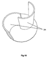
- contra-rotating turbine rotors on alternate modules as shown in the partial section view in Figure 16.
- Figures 16 illustrates the use of segmented Savonius turbine rotors, the top side of the turbine rotor 202 rotating into the page and the top side of the turbine rotor 204 rotating out of the page, it is however possible that any contra-rotating blade geometry may be applied.
- This optional feature allows the possibility of turning the generator at a faster rotational speed by driving the stator and rotor of an electrical generator 150 in opposite directions by coupling the generator centrally between modules, the turbine rotor 202 on one side driving the generator stator 206 and the turbine rotor 204 on the other side driving the generator rotor 208.
- contra-rotating turbine rotors to drive an electrical generator at an increased rotational speed is known in the field of axial flow wind turbines and is described in Patent Application GB2441770 .
- the generator 150 may be located away from the end of the turbine assembly and driven through a transmission means 160.
- Figure 15 shows a turbine assembly installation according to the third embodiment of the invention in which the generator 150 is located inside the roof space of the building, and is connected to the rotor 20 by a gear train, belt, chain or other transmission means 160.
- the rotor 20 preferably has between 2 and 20 blades 30 and more preferably between 2 and 5 blades 30. However, other embodiments of the invention may have any number of blades 30.
- the rotor 20 may have one of several different blade cross section geometries.
- the blades 30 project perpendicularly from the hub 22, and have a curved portion 32 at their tip. This improves the efficiency of the rotor 20 when used in air flows which are directed towards the concave side of the curved portion 32 of the blade 30.
- Rotors 20 having this geometry therefore have a preferred direction of rotation, i.e. they experience more drag on one side of the blade 30 than on the other side of the blade 30.
- the rotor 20 may have two separate curved blades 34 with or without a central hub 22.
- the two blades 34 are oriented so as to overlap at their inner edges with the inner edge of each blade extending beyond the axis of rotation 94 into the opposite side of the rotor to that containing the main portion of the blade.
- a turbine assembly having this arrangement of blades 34 is commonly known as a Savonius turbine.
- the degree of curvature on each of the curved blades 34 can be varied.
- Figure 19 shows another embodiment of a Savonius rotor in which the innermost portion of each blade 34 is substantially linear, each blade 34 being positioned to provide a degree of overlap between the inner edges of the blades 34.
- the gap between the inner edges of the two blades 34 is configured to allow a portion of the air flow impinging on one blade 34 to "cross feed" to the opposite blade 34 thus providing additional motive power.
- This cross feed is illustrated in Figure 19 where the air flow 80 impinges on one blade 34 and a portion 82 of this flow is directed between the two blades 34 and impinges on the second blade 34, allowing the second blade 34 to also extract useful energy from the air flow.
- the rotor 20 may have one of several different arrangements of the blades 30 along the length of the rotor 20. In one embodiment, shown in Figure 20 , each of the blades 30 adjoins the hub 22 parallel to the axis of rotation 94 of the rotor 20.
- each of the blades 30 adjoins the hub 22 in a helical path along the length of the rotor 20.
- Figure 21 illustrates such a helical blade 30 arrangement in which the tip of each blade 30 forms a helix and the surface of each blade 30 forming a helicoid.
- This type of blade geometry may be referred to as a single spiral rotor.
- This single spiral rotor geometry results in a portion of at least one blade 30 always being substantially perpendicular to the air stream (assuming that the rotor spiral twists through at least 360°/(number of blades)). This ensures that the rotor 20 can start from any stationary position assuming the airflow enters the assembly substantially perpendicular to the axis of rotation 94 of the rotor.
- each of the blades 30 adjoins the hub 22 along a path which is formed by a right handed helix originating from one end of the rotor 20 and a left handed helix originating from the opposite end of the rotor 20, the two helices meeting in the centre of the rotor 20.
- This arrangement of blades is shown in Figure 22 and may be referred to as a double spiral rotor.
- Turbine assemblies 10, 90, 100, 200 according to the invention which utilise a single spiral rotor may be optimised for air flows which impinge on the blade 30 in a direction perpendicular to the blade surface.
- the angle of this air flow relative to the axis of rotation 94 of the turbine assembly will vary from 90°, with the degree of variation being dependent upon the degree of helical twist on the blade. In this way, it is possible to optimise the blade geometry for a given installation orientation.
- Figure 21 shows a single spiral rotor 20 the axis 94 of which is aligned in a North-South direction, and the blade tip curvatures are arranged such that air flows in an East to West direction travel under the rotor 20.
- the spiral geometry of the rotor shown in Figure 21 results in the blade surfaces being aligned so as to face a more Northerly direction. This arrangement of rotor 20 will therefore favour air flows from the North East over flows from the South East.
- a rotor 20 having a double spiral rotor geometry provides the advantages of spiral rotor geometry without the limitation of favouring air flows from a particular direction.
- the rotor parameters, spiral type, blade tip curvature direction and spiral direction can be selected so as to provide the optimum output from the turbine assembly 10, 90, 100, 200 for a given installation direction and prevailing air flow conditions.
- the rotor 20 may include blades 30 which are aligned parallel to the axis of rotation 94 of the rotor 20 together with a plurality of separator discs 70, as shown in Figure 23 .
- These separator discs 70 are located concentrically with the axis of rotation 94 of the rotor and are spaced along the rotor 20 so as to divide the rotor 20 into segments.
- the separator discs 70 may take the form of solid discs, perforated discs or partial discs. While the separator discs 70 are generally arranged to be perpendicular to the axis of rotation 94 of the rotor 20, other orientations are envisaged.
- Each of the segments may be rotated through a pre-determined angle to produce a rotor 20 having blade segments which are disposed helically around the rotor 20.
- separator discs 70 can limit span wise air flows along the rotor 20 and thus allow energy to be transferred from the air stream to the rotor 20, equally across the span of the rotor 20 and in the area where the air first impinged upon the blades. This can be especially important for single and double spiral rotors in which the wind direction varies from the optimum, and where air flow would otherwise roll along the length of the rotor 20.
- the separator discs 70 can increase the rigidity of the rotor 20 assembly. They can also provide for modular rotor construction which may decrease construction costs and can allow for replacement of sections in service.
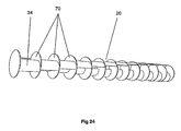
- a rotor 20 having Savonius style blades 34 may also be fitted with separator discs 70, as can be seen in Figure 24 .
- a rotor 20 having Savonius style blades 34 and separator discs 70 may also include a hub 22.
- each building or structure is each fitted with a roof mounted turbine assembly according to the invention and an associated electrical generator 150
- the electrical outputs from the generators 150 may be interconnected to form a community generating scheme.
- Each individual turbine assembly 10, 90, 100, 200 may optionally have a rotor geometry optimised for the prevailing wind speed and direction relative to the orientation of the roof of the building.
- Figure 25 shows a schematic arrangement of one embodiment of such a community generating scheme. This arrangement would allow the users of the scheme to consume electricity generated by the turbine assemblies 10, 90, 100, 200, and other generating devices using renewable energy sources such as photovoltaic cells, in preference to electricity supplied from a remote generating site. Surplus electricity generated by the turbine assemblies 10, 90, 100, 200 could be stored in batteries for later use.
- surplus electricity could be used to heat water, operate ground-source, water-source or air-source heat pumps or could be returned to a power distribution network on a commercial basis.
- the turbine assembly 10, 90, 100, 200 lends itself to other applications including installation on temporary structures and vehicles.
- the turbine assembly 10, 90, 100, 200 may also be operated in an airborne arrangement, in which it is suspended from a kite.
Claims (17)
- Ensemble éolienne à flux transversal (10, 90 100, 200) comprenant un rotor (20) ayant une pluralité de pales (30), et un carénage (40) comprenant au moins deux portions de carénage (42, 44, 46, 48, 110, 112, 114, 210, 212, 214), s'étendant axialement le long du rotor et autour du rotor pour au moins partiellement enfermer le rotor, au moins deux portions de carénage pouvant être ajustées en rotation afin d'exposer une portion du rotor au vent, et dans lequel le carénage, en utilisation, définit une admission variable (50) et un refoulement variable (52) moyennant quoi, en utilisation, l'aire d'admission (50) et l'aire de refoulement (52) sont variables indépendamment l'une de l'autre en aire et en position angulaire autour de la circonférence de l'éolienne.
- Ensemble éolienne à flux transversal selon la revendication 1, dans lequel une ou plusieurs portions de carénage sont espacées transversalement de l'axe de rotation (94) du rotor d'une distance qui est différente de la distance de laquelle les une ou plusieurs autres portions de carénage sont espacées transversalement de l'axe de rotation (94) du rotor.
- Ensemble éolienne à flux transversal selon la revendication 1 ou 2, dans lequel la distance de laquelle une ou plusieurs portions de carénage sont espacées (96), transversalement de l'axe de rotation (92) de la portion de carénage, varie avec la position angulaire de la portion de carénage respective par rapport à l'axe de rotation (92) de la portion de carénage.
- Ensemble éolienne à flux transversal selon l'une quelconque des revendications précédentes, dans lequel la distance de laquelle une ou plusieurs portions de carénage sont espacées (96, 97, 98), transversalement de l'axe de rotation (92) de la portion de carénage, varie avec la position angulaire autour de la portion de carénage respective.
- Ensemble éolienne à flux transversal selon l'une quelconque des revendications précédentes, dans lequel l'axe de rotation (92) d'une ou plusieurs portions de carénage et l'axe de rotation (94) du rotor sont coaxiaux.
- Ensemble éolienne à flux transversal selon l'une quelconque des revendications précédentes, dans lequel les axes de rotation (92) d'une ou plusieurs portions de carénage sont décalés par rapport à l'axe de rotation (94) du rotor.
- Ensemble éolienne à flux transversal selon l'une quelconque des revendications précédentes, dans lequel l'axe de rotation (92) d'une ou plusieurs portions de carénage varie par rapport à l'axe de rotation (94) du rotor à mesure que les une ou plusieurs portions de carénage tournent
- Ensemble éolienne à flux transversal selon l'une quelconque des revendications précédentes, dans lequel une ou plusieurs portions de carénage incluent un guide d'admission (56) s'étendant axialement le long de la portion de carénage.
- Ensemble éolienne à flux transversal selon l'une quelconque des revendications précédente, dans lequel une ou plusieurs portions de carénage incluent un guide d'échappement (58), le guide d'échappement, s'étendant axialement le long de la portion de carénage.
- Ensemble éolienne à flux transversal selon l'une quelconque des revendications précédentes, dans lequel une ou plusieurs portions de carénage comprennent un dispositif d'inversion de flux (60).
- Ensemble éolienne à flux transversal selon l'une quelconque des revendications précédentes, dans lequel une ou plusieurs portions de carénage incluent une pluralité d'ouvertures (62).
- Ensemble éolienne à flux transversal selon l'une quelconque des revendications précédentes, comprenant en outre un capteur de vibration (116) permettant de mesurer une vibration de l'éolienne.
- Procédé d'exploitation d'un ensemble éolienne à flux transversal (10, 90, 100, 200) du type défini dans l'une quelconque des revendications 1 à 12, dans lequel le rotor (20) est raccordé à un générateur électrique (150) ; le procédé comprenant les étapes consistant à :ajuster la position de rotation des portions de carénage (42, 44, 46, 48, 110,112,114,210,212,214);déterminer la sortie de puissance électrique du générateur électrique ; etrépéter les étapes ci-dessus afin d'atteindre une sortie de puissance électrique requise du générateur électrique.
- Procédé d'exploitation d'un ensemble éolienne à flux transversal selon la revendication 13, l'ensemble éolienne comprenant en outre une pluralité de capteurs (118), chaque capteur (118) étant adapté pour capter une variable, le procédé comprenant les étapes initiales additionnelles consistant à :recevoir une entrée d'un ou plusieurs de la pluralité de capteurs (118) ;comparer l'entrée à une valeur prédéterminée ; etutiliser les résultats de l'étape de comparaison pour déterminer l'ajustement requis à effectuer sur la position du carénage.
- Procédé d'exploitation d'un ensemble éolienne à flux transversal selon la revendication 14, dans lequel la variable est choisie dans le groupe comprenant la vitesse du vent, la direction du vent, la température, l'humidité, la vibration et la pression.
- Toit pour bâtiment comprenant un ensemble éolienne à flux transversal selon l'une quelconque des revendications 1 à 12, le toit comprenant un sommet, l'ensemble éolienne étant positionné sensiblement parallèlement au sommet du toit.
- Série de modules d'éolienne à flux transversal installés en série le long du sommet d'un toit en conformité avec la revendication 16, dans laquelle les rotors de modules d'éolienne alternés sont contrarotatifs, un générateur (150) couplé centralement entre des modules alternés, le rotor (202) d'un module entraînant le stator (206) du générateur (150) et le rotor (204) du module adjacent entraînant le rotor (208) du générateur (150).
Applications Claiming Priority (2)
| Application Number | Priority Date | Filing Date | Title |
|---|---|---|---|
| GBGB0904816.6A GB0904816D0 (en) | 2009-03-20 | 2009-03-20 | Turbine assembly |
| PCT/GB2010/000507 WO2010106337A2 (fr) | 2009-03-20 | 2010-03-18 | Ensemble turbine |
Publications (2)
| Publication Number | Publication Date |
|---|---|
| EP2409024A2 EP2409024A2 (fr) | 2012-01-25 |
| EP2409024B1 true EP2409024B1 (fr) | 2013-03-13 |
Family
ID=40639876
Family Applications (1)
| Application Number | Title | Priority Date | Filing Date |
|---|---|---|---|
| EP10723245A Active EP2409024B1 (fr) | 2009-03-20 | 2010-03-18 | Ensemble turbine |
Country Status (5)
| Country | Link |
|---|---|
| US (1) | US8786123B2 (fr) |
| EP (1) | EP2409024B1 (fr) |
| DK (1) | DK2409024T3 (fr) |
| GB (1) | GB0904816D0 (fr) |
| WO (1) | WO2010106337A2 (fr) |
Cited By (1)
| Publication number | Priority date | Publication date | Assignee | Title |
|---|---|---|---|---|
| DE102018122090A1 (de) * | 2018-09-11 | 2020-03-12 | Franz Blum | Windturbinenmodul, Windturbinenanordnung und Windturbine |
Families Citing this family (22)
| Publication number | Priority date | Publication date | Assignee | Title |
|---|---|---|---|---|
| US8148839B2 (en) | 2008-07-02 | 2012-04-03 | Rosefsky Jonathan B | Ribbon drive power generation and method of use |
| US7744338B2 (en) * | 2008-09-04 | 2010-06-29 | California Energy & Power | Fluid turbine systems |
| GB0912695D0 (en) * | 2009-07-22 | 2009-08-26 | Power Collective The Ltd | A generator |
| FR2964421B1 (fr) * | 2010-09-02 | 2013-04-05 | Aeolta Sas | Dispositif d'eolienne de toiture |
| NL2005540C2 (nl) * | 2010-10-18 | 2012-04-19 | Stichting S & O Patenten | Inrichting en werkwijze voor het uitwisselen van energie met een fluïdum. |
| GB201104929D0 (en) * | 2011-03-24 | 2011-05-04 | Liverpool Renewable Energy Res Ct The | Multiple savonius turbines |
| AT511692B1 (de) * | 2011-11-11 | 2013-02-15 | Cuba Norbert | Turbine, insbesondere windturbine |
| HUP1200001A2 (en) * | 2012-01-02 | 2013-07-29 | Gabor Dr Havas | Wind motor with rotation axis substantially at right angle to wind direction with a multistage acceleration system |
| BR102012005018A2 (pt) * | 2012-03-06 | 2013-11-26 | Akitoshi Murata | Disposição construtiva em sistema de turbina eólica |
| DK2920461T3 (en) | 2012-11-19 | 2018-06-25 | Revoluter Ltd | FLOW OPTIMIZATION LAYOUT |
| US20140255190A1 (en) * | 2013-03-05 | 2014-09-11 | Akitoshi Murata | Wind Turbine System Constructive Arrangement |
| ITBO20130423A1 (it) * | 2013-07-31 | 2015-02-01 | Sandra Castaldini | Generatore ausiliario di energia elettrica. |
| US9850877B2 (en) | 2013-09-23 | 2017-12-26 | George F McBride | Spent flow discharge apparatus for an instream fluid power-extraction machine |
| US9689372B2 (en) * | 2013-10-08 | 2017-06-27 | Aurelio Izquierdo Gonzalez | Vertical-axis wind turbine with protective screen |
| KR101792251B1 (ko) * | 2014-11-26 | 2017-12-01 | 선상규 | 바람가이드를 갖는 나선형 블레이드 |
| US20170234302A1 (en) * | 2015-11-25 | 2017-08-17 | Hattar Tanin LLC | Innovative wind turbine construction for 100% energy independence or even being energy positive |
| US10487799B2 (en) * | 2015-12-18 | 2019-11-26 | Dan Pendergrass | Pressure and vacuum assisted vertical axis wind turbines |
| WO2017144837A1 (fr) * | 2016-02-27 | 2017-08-31 | Stephen John Mcloughlin | Système, procédé et application de turbine éolienne |
| US10704532B2 (en) * | 2016-04-14 | 2020-07-07 | Ronald GDOVIC | Savonius wind turbines |
| CN107989745B (zh) * | 2017-12-30 | 2023-08-29 | 长沙紫宸科技开发有限公司 | 一种便携式汇风涵道风力发电器 |
| GB201818858D0 (en) * | 2018-11-20 | 2019-01-02 | Lithgow William | A free stream turbine and system |
| CN110777966B (zh) * | 2019-11-05 | 2020-11-17 | 台州学院 | 一种可导风的抗风墙块结构 |
Family Cites Families (15)
| Publication number | Priority date | Publication date | Assignee | Title |
|---|---|---|---|---|
| DE2924970A1 (de) | 1979-06-21 | 1981-01-29 | Schmols Karl Heinz | Windkraftanlagen |
| DE3315439A1 (de) | 1983-04-28 | 1984-10-31 | Dornier Gmbh, 7990 Friedrichshafen | Einrichtung zur umformung der natuerlichen stroemungsenergie von wasser bzw. luft |
| DE19607592A1 (de) * | 1996-02-29 | 1997-09-04 | Hannig Norbert | Strömungsturbine zur Nutzung von Luft- und Wasserströmungen zur Elektrizitätserzeugung oder Arbeitsleistung |
| DE19644890A1 (de) | 1996-10-29 | 1998-04-30 | Ralf Huber | Dachgiebelintegriertes Windenergiekonvertersystem |
| DE19828324A1 (de) * | 1998-06-25 | 1999-12-30 | Heinrich Bastian | Windturbine für Haus und Dachkonstruktionen |
| DE19853790A1 (de) | 1998-11-21 | 2000-05-31 | Wilhelm Groppel | Windkraftanlage |
| CA2387434A1 (fr) | 2002-05-17 | 2003-11-17 | Bud T.J. Johnson | Turbine eolienne de type volumetrique, a admission amelioree et a commande d'ouverture |
| US6984899B1 (en) * | 2004-03-01 | 2006-01-10 | The United States Of America As Represented By The Secretary Of The Navy | Wind dam electric generator and method |
| JP4677631B2 (ja) * | 2005-03-25 | 2011-04-27 | 国立大学法人東北大学 | 風荷重低減装置および風力発電システム |
| JP4814644B2 (ja) * | 2006-02-01 | 2011-11-16 | 富士重工業株式会社 | 風力発電装置 |
| ITBO20060786A1 (it) | 2006-11-20 | 2008-05-21 | Know How Italia S P A | Apparecchiatura eolica |
| WO2009009701A2 (fr) * | 2007-07-10 | 2009-01-15 | California Wind Systems | Eolienne latérale |
| DE102007032843B4 (de) * | 2007-07-12 | 2015-07-30 | Wilfried Färber | Walzen-Windgenerator zur Stromerzeugung |
| US8102071B2 (en) * | 2007-10-18 | 2012-01-24 | Catlin Christopher S | River and tidal power harvester |
| GB0912695D0 (en) * | 2009-07-22 | 2009-08-26 | Power Collective The Ltd | A generator |
-
2009
- 2009-03-20 GB GBGB0904816.6A patent/GB0904816D0/en not_active Ceased
-
2010
- 2010-03-18 WO PCT/GB2010/000507 patent/WO2010106337A2/fr active Application Filing
- 2010-03-18 EP EP10723245A patent/EP2409024B1/fr active Active
- 2010-03-18 US US13/138,667 patent/US8786123B2/en active Active
- 2010-03-18 DK DK10723245.6T patent/DK2409024T3/da active
Cited By (2)
| Publication number | Priority date | Publication date | Assignee | Title |
|---|---|---|---|---|
| DE102018122090A1 (de) * | 2018-09-11 | 2020-03-12 | Franz Blum | Windturbinenmodul, Windturbinenanordnung und Windturbine |
| DE102018122090B4 (de) | 2018-09-11 | 2022-08-18 | Franz Blum | Windturbinenmodul, Windturbinenanordnung und Windturbine |
Also Published As
| Publication number | Publication date |
|---|---|
| GB0904816D0 (en) | 2009-05-06 |
| WO2010106337A2 (fr) | 2010-09-23 |
| US8786123B2 (en) | 2014-07-22 |
| WO2010106337A3 (fr) | 2011-05-26 |
| US20120007362A1 (en) | 2012-01-12 |
| DK2409024T3 (da) | 2013-05-21 |
| EP2409024A2 (fr) | 2012-01-25 |
Similar Documents
| Publication | Publication Date | Title |
|---|---|---|
| EP2409024B1 (fr) | Ensemble turbine | |
| US20200362813A1 (en) | Fluid turbine systems | |
| EP2609325B1 (fr) | Turbine à axe vertical | |
| US20100296913A1 (en) | Wind power generating system with vertical axis jet wheel turbine | |
| US20080131273A1 (en) | Wind turbine for generation of electric power | |
| US20140356163A1 (en) | Turbomachine | |
| EP2507510B1 (fr) | Turbine | |
| US20110318167A1 (en) | Crossflow wind turbine | |
| WO2006123951A1 (fr) | Eolienne | |
| EP4088021B1 (fr) | Systèmes et procédés de captage d'énergie à partir du vent | |
| RU2736680C1 (ru) | Гелиоветровая энергетическая установка повышенной мощности | |
| WO2011061558A1 (fr) | Turbine éolienne omnidirectionnelle pour une génération d'énergie | |
| WO2024005725A1 (fr) | Cheminée éolienne | |
| WO2022130244A1 (fr) | Éolienne | |
| CN114667391A (zh) | 风轮机和基于该风轮机的风力发电站 |
Legal Events
| Date | Code | Title | Description |
|---|---|---|---|
| PUAI | Public reference made under article 153(3) epc to a published international application that has entered the european phase |
Free format text: ORIGINAL CODE: 0009012 |
|
| 17P | Request for examination filed |
Effective date: 20110916 |
|
| AK | Designated contracting states |
Kind code of ref document: A2 Designated state(s): AT BE BG CH CY CZ DE DK EE ES FI FR GB GR HR HU IE IS IT LI LT LU LV MC MK MT NL NO PL PT RO SE SI SK SM TR |
|
| DAX | Request for extension of the european patent (deleted) | ||
| GRAP | Despatch of communication of intention to grant a patent |
Free format text: ORIGINAL CODE: EPIDOSNIGR1 |
|
| GRAS | Grant fee paid |
Free format text: ORIGINAL CODE: EPIDOSNIGR3 |
|
| GRAA | (expected) grant |
Free format text: ORIGINAL CODE: 0009210 |
|
| AK | Designated contracting states |
Kind code of ref document: B1 Designated state(s): AT BE BG CH CY CZ DE DK EE ES FI FR GB GR HR HU IE IS IT LI LT LU LV MC MK MT NL NO PL PT RO SE SI SK SM TR |
|
| REG | Reference to a national code |
Ref country code: GB Ref legal event code: FG4D |
|
| REG | Reference to a national code |
Ref country code: CH Ref legal event code: EP Ref country code: AT Ref legal event code: REF Ref document number: 600958 Country of ref document: AT Kind code of ref document: T Effective date: 20130315 |
|
| REG | Reference to a national code |
Ref country code: IE Ref legal event code: FG4D |
|
| REG | Reference to a national code |
Ref country code: DE Ref legal event code: R096 Ref document number: 602010005474 Country of ref document: DE Effective date: 20130508 |
|
| REG | Reference to a national code |
Ref country code: DK Ref legal event code: T3 |
|
| REG | Reference to a national code |
Ref country code: SE Ref legal event code: TRGR |
|
| PG25 | Lapsed in a contracting state [announced via postgrant information from national office to epo] |
Ref country code: ES Free format text: LAPSE BECAUSE OF FAILURE TO SUBMIT A TRANSLATION OF THE DESCRIPTION OR TO PAY THE FEE WITHIN THE PRESCRIBED TIME-LIMIT Effective date: 20130624 Ref country code: LT Free format text: LAPSE BECAUSE OF FAILURE TO SUBMIT A TRANSLATION OF THE DESCRIPTION OR TO PAY THE FEE WITHIN THE PRESCRIBED TIME-LIMIT Effective date: 20130313 Ref country code: NO Free format text: LAPSE BECAUSE OF FAILURE TO SUBMIT A TRANSLATION OF THE DESCRIPTION OR TO PAY THE FEE WITHIN THE PRESCRIBED TIME-LIMIT Effective date: 20130613 Ref country code: BG Free format text: LAPSE BECAUSE OF FAILURE TO SUBMIT A TRANSLATION OF THE DESCRIPTION OR TO PAY THE FEE WITHIN THE PRESCRIBED TIME-LIMIT Effective date: 20130613 |
|
| REG | Reference to a national code |
Ref country code: NL Ref legal event code: T3 |
|
| REG | Reference to a national code |
Ref country code: AT Ref legal event code: MK05 Ref document number: 600958 Country of ref document: AT Kind code of ref document: T Effective date: 20130313 |
|
| REG | Reference to a national code |
Ref country code: LT Ref legal event code: MG4D |
|
| PG25 | Lapsed in a contracting state [announced via postgrant information from national office to epo] |
Ref country code: FI Free format text: LAPSE BECAUSE OF FAILURE TO SUBMIT A TRANSLATION OF THE DESCRIPTION OR TO PAY THE FEE WITHIN THE PRESCRIBED TIME-LIMIT Effective date: 20130313 Ref country code: SI Free format text: LAPSE BECAUSE OF FAILURE TO SUBMIT A TRANSLATION OF THE DESCRIPTION OR TO PAY THE FEE WITHIN THE PRESCRIBED TIME-LIMIT Effective date: 20130313 Ref country code: LV Free format text: LAPSE BECAUSE OF FAILURE TO SUBMIT A TRANSLATION OF THE DESCRIPTION OR TO PAY THE FEE WITHIN THE PRESCRIBED TIME-LIMIT Effective date: 20130313 Ref country code: GR Free format text: LAPSE BECAUSE OF FAILURE TO SUBMIT A TRANSLATION OF THE DESCRIPTION OR TO PAY THE FEE WITHIN THE PRESCRIBED TIME-LIMIT Effective date: 20130614 |
|
| PG25 | Lapsed in a contracting state [announced via postgrant information from national office to epo] |
Ref country code: HR Free format text: LAPSE BECAUSE OF FAILURE TO SUBMIT A TRANSLATION OF THE DESCRIPTION OR TO PAY THE FEE WITHIN THE PRESCRIBED TIME-LIMIT Effective date: 20130313 Ref country code: BE Free format text: LAPSE BECAUSE OF FAILURE TO SUBMIT A TRANSLATION OF THE DESCRIPTION OR TO PAY THE FEE WITHIN THE PRESCRIBED TIME-LIMIT Effective date: 20130313 |
|
| PG25 | Lapsed in a contracting state [announced via postgrant information from national office to epo] |
Ref country code: EE Free format text: LAPSE BECAUSE OF FAILURE TO SUBMIT A TRANSLATION OF THE DESCRIPTION OR TO PAY THE FEE WITHIN THE PRESCRIBED TIME-LIMIT Effective date: 20130313 Ref country code: RO Free format text: LAPSE BECAUSE OF FAILURE TO SUBMIT A TRANSLATION OF THE DESCRIPTION OR TO PAY THE FEE WITHIN THE PRESCRIBED TIME-LIMIT Effective date: 20130313 Ref country code: PT Free format text: LAPSE BECAUSE OF FAILURE TO SUBMIT A TRANSLATION OF THE DESCRIPTION OR TO PAY THE FEE WITHIN THE PRESCRIBED TIME-LIMIT Effective date: 20130715 Ref country code: AT Free format text: LAPSE BECAUSE OF FAILURE TO SUBMIT A TRANSLATION OF THE DESCRIPTION OR TO PAY THE FEE WITHIN THE PRESCRIBED TIME-LIMIT Effective date: 20130313 Ref country code: CZ Free format text: LAPSE BECAUSE OF FAILURE TO SUBMIT A TRANSLATION OF THE DESCRIPTION OR TO PAY THE FEE WITHIN THE PRESCRIBED TIME-LIMIT Effective date: 20130313 Ref country code: SK Free format text: LAPSE BECAUSE OF FAILURE TO SUBMIT A TRANSLATION OF THE DESCRIPTION OR TO PAY THE FEE WITHIN THE PRESCRIBED TIME-LIMIT Effective date: 20130313 Ref country code: IS Free format text: LAPSE BECAUSE OF FAILURE TO SUBMIT A TRANSLATION OF THE DESCRIPTION OR TO PAY THE FEE WITHIN THE PRESCRIBED TIME-LIMIT Effective date: 20130713 Ref country code: MC Free format text: LAPSE BECAUSE OF NON-PAYMENT OF DUE FEES Effective date: 20130331 |
|
| PG25 | Lapsed in a contracting state [announced via postgrant information from national office to epo] |
Ref country code: PL Free format text: LAPSE BECAUSE OF FAILURE TO SUBMIT A TRANSLATION OF THE DESCRIPTION OR TO PAY THE FEE WITHIN THE PRESCRIBED TIME-LIMIT Effective date: 20130313 |
|
| REG | Reference to a national code |
Ref country code: IE Ref legal event code: MM4A |
|
| PLBE | No opposition filed within time limit |
Free format text: ORIGINAL CODE: 0009261 |
|
| STAA | Information on the status of an ep patent application or granted ep patent |
Free format text: STATUS: NO OPPOSITION FILED WITHIN TIME LIMIT |
|
| PG25 | Lapsed in a contracting state [announced via postgrant information from national office to epo] |
Ref country code: IE Free format text: LAPSE BECAUSE OF NON-PAYMENT OF DUE FEES Effective date: 20130318 |
|
| 26N | No opposition filed |
Effective date: 20131216 |
|
| PG25 | Lapsed in a contracting state [announced via postgrant information from national office to epo] |
Ref country code: IT Free format text: LAPSE BECAUSE OF FAILURE TO SUBMIT A TRANSLATION OF THE DESCRIPTION OR TO PAY THE FEE WITHIN THE PRESCRIBED TIME-LIMIT Effective date: 20130313 |
|
| REG | Reference to a national code |
Ref country code: DE Ref legal event code: R097 Ref document number: 602010005474 Country of ref document: DE Effective date: 20131216 |
|
| PG25 | Lapsed in a contracting state [announced via postgrant information from national office to epo] |
Ref country code: MT Free format text: LAPSE BECAUSE OF FAILURE TO SUBMIT A TRANSLATION OF THE DESCRIPTION OR TO PAY THE FEE WITHIN THE PRESCRIBED TIME-LIMIT Effective date: 20130313 |
|
| REG | Reference to a national code |
Ref country code: CH Ref legal event code: PL |
|
| PG25 | Lapsed in a contracting state [announced via postgrant information from national office to epo] |
Ref country code: LI Free format text: LAPSE BECAUSE OF NON-PAYMENT OF DUE FEES Effective date: 20140331 Ref country code: CH Free format text: LAPSE BECAUSE OF NON-PAYMENT OF DUE FEES Effective date: 20140331 |
|
| PG25 | Lapsed in a contracting state [announced via postgrant information from national office to epo] |
Ref country code: SM Free format text: LAPSE BECAUSE OF FAILURE TO SUBMIT A TRANSLATION OF THE DESCRIPTION OR TO PAY THE FEE WITHIN THE PRESCRIBED TIME-LIMIT Effective date: 20130313 |
|
| PG25 | Lapsed in a contracting state [announced via postgrant information from national office to epo] |
Ref country code: CY Free format text: LAPSE BECAUSE OF FAILURE TO SUBMIT A TRANSLATION OF THE DESCRIPTION OR TO PAY THE FEE WITHIN THE PRESCRIBED TIME-LIMIT Effective date: 20130313 Ref country code: TR Free format text: LAPSE BECAUSE OF FAILURE TO SUBMIT A TRANSLATION OF THE DESCRIPTION OR TO PAY THE FEE WITHIN THE PRESCRIBED TIME-LIMIT Effective date: 20130313 |
|
| PG25 | Lapsed in a contracting state [announced via postgrant information from national office to epo] |
Ref country code: LU Free format text: LAPSE BECAUSE OF NON-PAYMENT OF DUE FEES Effective date: 20130318 Ref country code: HU Free format text: LAPSE BECAUSE OF FAILURE TO SUBMIT A TRANSLATION OF THE DESCRIPTION OR TO PAY THE FEE WITHIN THE PRESCRIBED TIME-LIMIT; INVALID AB INITIO Effective date: 20100318 Ref country code: MK Free format text: LAPSE BECAUSE OF FAILURE TO SUBMIT A TRANSLATION OF THE DESCRIPTION OR TO PAY THE FEE WITHIN THE PRESCRIBED TIME-LIMIT Effective date: 20130313 |
|
| REG | Reference to a national code |
Ref country code: FR Ref legal event code: PLFP Year of fee payment: 7 |
|
| REG | Reference to a national code |
Ref country code: FR Ref legal event code: PLFP Year of fee payment: 8 |
|
| REG | Reference to a national code |
Ref country code: FR Ref legal event code: PLFP Year of fee payment: 9 |
|
| PGFP | Annual fee paid to national office [announced via postgrant information from national office to epo] |
Ref country code: SE Payment date: 20220930 Year of fee payment: 13 Ref country code: NL Payment date: 20220929 Year of fee payment: 13 Ref country code: DE Payment date: 20220929 Year of fee payment: 13 |
|
| PGFP | Annual fee paid to national office [announced via postgrant information from national office to epo] |
Ref country code: FR Payment date: 20220929 Year of fee payment: 13 |
|
| PGFP | Annual fee paid to national office [announced via postgrant information from national office to epo] |
Ref country code: DK Payment date: 20230329 Year of fee payment: 14 |
|
| REG | Reference to a national code |
Ref country code: DE Ref legal event code: R119 Ref document number: 602010005474 Country of ref document: DE |
|
| PGFP | Annual fee paid to national office [announced via postgrant information from national office to epo] |
Ref country code: GB Payment date: 20230906 Year of fee payment: 14 |
|
| REG | Reference to a national code |
Ref country code: SE Ref legal event code: EUG |
|
| REG | Reference to a national code |
Ref country code: NL Ref legal event code: MM Effective date: 20230401 |
|
| PG25 | Lapsed in a contracting state [announced via postgrant information from national office to epo] |
Ref country code: NL Free format text: LAPSE BECAUSE OF NON-PAYMENT OF DUE FEES Effective date: 20230401 |
|
| PG25 | Lapsed in a contracting state [announced via postgrant information from national office to epo] |
Ref country code: SE Free format text: LAPSE BECAUSE OF NON-PAYMENT OF DUE FEES Effective date: 20230319 Ref country code: FR Free format text: LAPSE BECAUSE OF NON-PAYMENT OF DUE FEES Effective date: 20230331 Ref country code: DE Free format text: LAPSE BECAUSE OF NON-PAYMENT OF DUE FEES Effective date: 20231003 |