EP2408652B1 - Bremsvorrichtung zur indexierung der position eines am ende einer mit einer wand eines bremsverstärkers verbundenen kupplung positionierten sensors - Google Patents
Bremsvorrichtung zur indexierung der position eines am ende einer mit einer wand eines bremsverstärkers verbundenen kupplung positionierten sensors Download PDFInfo
- Publication number
- EP2408652B1 EP2408652B1 EP10716402A EP10716402A EP2408652B1 EP 2408652 B1 EP2408652 B1 EP 2408652B1 EP 10716402 A EP10716402 A EP 10716402A EP 10716402 A EP10716402 A EP 10716402A EP 2408652 B1 EP2408652 B1 EP 2408652B1
- Authority
- EP
- European Patent Office
- Prior art keywords
- sensor
- coupling
- braking
- connector
- amplifier
- Prior art date
- Legal status (The legal status is an assumption and is not a legal conclusion. Google has not performed a legal analysis and makes no representation as to the accuracy of the status listed.)
- Active
Links
Images

Classifications
-
- B—PERFORMING OPERATIONS; TRANSPORTING
- B60—VEHICLES IN GENERAL
- B60T—VEHICLE BRAKE CONTROL SYSTEMS OR PARTS THEREOF; BRAKE CONTROL SYSTEMS OR PARTS THEREOF, IN GENERAL; ARRANGEMENT OF BRAKING ELEMENTS ON VEHICLES IN GENERAL; PORTABLE DEVICES FOR PREVENTING UNWANTED MOVEMENT OF VEHICLES; VEHICLE MODIFICATIONS TO FACILITATE COOLING OF BRAKES
- B60T13/00—Transmitting braking action from initiating means to ultimate brake actuator with power assistance or drive; Brake systems incorporating such transmitting means, e.g. air-pressure brake systems
- B60T13/10—Transmitting braking action from initiating means to ultimate brake actuator with power assistance or drive; Brake systems incorporating such transmitting means, e.g. air-pressure brake systems with fluid assistance, drive, or release
- B60T13/24—Transmitting braking action from initiating means to ultimate brake actuator with power assistance or drive; Brake systems incorporating such transmitting means, e.g. air-pressure brake systems with fluid assistance, drive, or release the fluid being gaseous
- B60T13/46—Vacuum systems
- B60T13/52—Vacuum systems indirect, i.e. vacuum booster units
- B60T13/567—Vacuum systems indirect, i.e. vacuum booster units characterised by constructional features of the casing or by its strengthening or mounting arrangements
Definitions
- the present invention relates to a braking device for a vehicle, in particular for a motor vehicle, comprising a braking amplifier, a connection fixed to a wall of a vacuum chamber of the braking amplifier and a sensor fixed by a nozzle to the fitting allowing an indexing in position of the sensor fixed on the tip of the fitting.
- the present invention also relates to a sensor comprising a seal ensuring the sealing of the assembly, the indexing means with the nozzle of the connector to prevent said seal from undergoing shear stresses, altering the seal of said assembly.
- connection has an opening, positioned along the mounting axis of this connection on the wall of the brake amplifier, allowing the introduction of a first portion of a pressure sensor.
- the pressure sensor has a second portion, protruding from the connector, having an electrical connector, positioned on one of these side surfaces, for connecting the pressure sensor to the electrical circuit of the vehicle.
- the pressure sensor is rather connected to the connection by a side nozzle, positioning the pressure sensor perpendicular to the axis of the engine. fitting of the fitting on the wall of the braking amplifier. Such positioning poses problems of orientation of the electrical connector, it can be found facing the wall of the vacuum chamber of the brake amplifier, no longer allowing its connection to the vehicle electrical circuit.
- the pressure sensor previously placed in position on the fitting (either at the edge of the chain or at the supplier of the brake amplifier), can have any position angular, that the operator may have to reposition it by turning it manually, degrading the seal by subjecting it to shear stresses, altering the tightness of the assembly.
- the object of the invention is to propose a device for fixing a sensor on a coupling, allowing by a simple means to implement, orient and maintain the sensor in a certain position on the coupling, avoiding any subsequent rotation may degrade a seal present between the sensor and the fitting.
- the invention relates to a braking device for a vehicle, in particular for a motor vehicle, according to the object of claim 1.
- the polarizing means comprise an opening formed on a bearing surface of the connector, receiving the sensor, and a finger integral with the sensor cooperating with said opening.
- the keying means comprise a finger secured to a bearing surface of the connector, receiving the sensor, and an opening formed on the sensor cooperating with said finger.
- the polarizing means comprise a finger projecting from the tip of the connector cooperating with said transverse surface.
- the projecting finger of the tip consists of the extension of a rib reinforcing the connection of the tip on the fitting.
- the invention also relates to a connection for a braking device having one of the preceding characteristics, comprising a tip adapted to receive a sensor, comprising keying means cooperating with said sensor to obtain a positional indexing of the sensor on said fitting.
- the figure 1 represents a braking amplifier 1 as well known to those skilled in the art.
- a braking amplifier 1 has an enclosure 2 comprising a front chamber 3 and a rear chamber 4, the front 3 and rear 4 chambers being separated by a membrane 5.
- a connection 6, according to the invention, is fixed along an axis of mounting X, via a sealing sleeve 7, in a circular opening of the wall 5 of the front chamber 3.
- the connector 6 has a main body 63 extending along the mounting axis X.
- the connection 6 comprises a first nozzle 61 for connecting a vacuum source (only a portion of the connecting pipe is represented) to the front chamber 3 of the braking amplifier 1 and a second end-piece 62 for mounting a pressure sensor 8.
- the first end-piece 61 and the second end-piece 62 are positioned along two axes, respectively, Y1 and Y2, positioned perpendicularly to the mounting axis X.
- the pressure sensor 8 is connected to the electrical circuit of the vehicle by an electrical connector 81 positioned on a surface laterally of the sensor 8, back to the wall 5 of the front chamber 3 allowing a easy access when connected to the vehicle's electrical system.
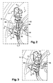
- FIGS. 2 and 3 show detailed views of the connector 6 and the pressure sensor 8, according to a first embodiment of the invention, positioned on the wall 5 of the front chamber 3 of the braking amplifier 1.
- the pressure sensor 8 is shown not positioned on the second nozzle 62 of the connector 6.
- the second nozzle 62 connected laterally to the main body 63 of the connector 6, has at its base a collar 64 forming a flat bearing surface to the sensor of pressure 8.
- An opening 65 is made on the edge of the flange 64.
- the pressure sensor 8 has a bearing surface 83 intended to bear against the flange 64 of the fitting 6. From this bearing surface 83 is extended a finger 82 adapted to collaborate with the opening 65 of the flange 64 of the connector 6.
- the pressure sensor 8 has a cylindrical internal surface forming the female part of the connection with the tip 62 of the connector 6. This cylindrical inner surface has an O-ring sealing the mounting.
- a flexible tab collaborating with a circular protrusion forming a ring 66 positioned parallel to the collar 64, on the lateral surface of the nozzle 62 of the connector 6.
- This flexible tab and the flange 64 form a clipping device ensuring the maintenance of the pressure sensor 8 along the tip 62 of the connector 6.
- the pressure sensor 8 is shown clipped on the second nozzle 62 of the connector 6.
- the finger 82 of the pressure sensor 8 comes into the opening 65 of the flange 64.
- the finger 82 of the pressure sensor 8 and the opening 65 of the connector 6 also act as a keying, positioning the electrical connector 81 back to the wall 5 of the front chamber 3 allowing its connection to the vehicle's electrical circuit.
- a misalignment of the finger 82 with the opening 65 does not make it possible to have the bearing surface 83 of the pressure sensor. bearing against the flange 64, not allowing the pressure sensor 8 to be clipped onto the connector 6. This gap is easily visible and makes it possible to check the conformity of the assembly.
- a variant of this embodiment may consist in positioning on the bearing surface of the flange 64 a finger extending in a direction normal to its surface collaborating with an opening made on the edge of the bearing surface 83 of the sensor
- This variant also makes it possible both to avoid any possible rotation of the pressure sensor 8 around the nozzle 62 of the connector 6, degrading the O-ring, and serves as a key to ensuring that the connector 81 is well oriented, facilitating its connection to the electrical circuit of the vehicle.
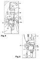
- FIGS. 4 and 5 show detailed views of the connector 6 and the pressure sensor 8, according to a second embodiment, positioned on the wall 5 of the front chamber of the braking amplifier 1.
- the pressure sensor 8 is shown not positioned on the second nozzle 62 of the connector 6.
- the peripheral surface of the pressure sensor juxtaposing the bearing surface 83 of the pressure sensor 8 does not is not cylindrical, but has a flat 84 positioned on the opposite side of the electrical connector 81.
- the second ferrule 62 as for the first embodiment, is connected laterally to the main body 63 of the connector 6, having a flange 64 forming a flat bearing face to the pressure sensor 8.
- the flange 64 has a spacing 62a with the main body 62 of the connector 6, thereby increasing the length of the the tip 62, weakening the connection between the nozzle 62 and the main body 63 of the connector 6.
- this spacing 62a is imposed by the method of manufacture, by molding, the connector 6.
- a transverse rib 67 is positioned between the main body 63 of the connector 6, the underside of the collar 64 and the lateral surface of the spacing 62a of the tip 62.
- An extension 68 of this rib 67 makes it possible to create a finger juxtaposing the collar 64, collaborating with the flat surface 84 of the pressure sensor 8, acting as a key during assembly of this pressure sensor 8 on the connector 6.
- the pressure sensor 8 is shown clipped on the nozzle 62 of the connector 6.
- An O-ring is always positioned between the pressure sensor and the nozzle 62, sealing the mounting.
- the extension 68 of the rib 67 is positioned with such a fate to come into contact with the flat part 84, blocking in rotation the pressure sensor 8 on the end piece 62 of the connector 6.
- the electrical connector 81 is thus positioned back to the wall 5 of the front chamber 3, allowing easy access when the electrical connector 81 is connected to the electric circuit of the vehicle.
Landscapes
- Engineering & Computer Science (AREA)
- Transportation (AREA)
- Mechanical Engineering (AREA)
- Valves And Accessory Devices For Braking Systems (AREA)
- Measuring Fluid Pressure (AREA)
Claims (8)
- Bremsvorrichtung für ein Fahrzeug, im Speziellen für ein Kraftfahrzeug, umfassend einen Bremsverstärker (1), einen Drucksensor (8), einen Anschluss (6), der an einer Wand (2) einer Unterdruckkammer (3) des Bremsverstärkers (1) befestigt ist, wobei der Anschluss (6) ein erstes Ansatzstück (61) umfasst, das geeignet ist, um die Unterdruckkammer (3) des Bremsverstärkers (1) mit einer Vakuumquelle zu verbinden, und ein zweites Ansatzstück (62), das geeignet ist, um eine Halterung für den besagten Sensor (8) zu bilden, und um den besagten Sensor (8) mit der Unterdruckkammer (3) des Bremsverstärkers (1) zu verbinden, dadurch gekennzeichnet, dass die Vorrichtung Unverwechselbarkeitseinrichtungen umfasst, die die Positionsindexierung des Sensors (8) am zweiten Ansatzstück (62) des Anschlusses (6) ermöglichen.
- Bremsvorrichtung nach Anspruch 1, dadurch gekennzeichnet, dass zwischen dem Sensor (8) und dem zweiten Ansatzstück (62) eine Dichtung eingefügt ist, wobei die besagte Dichtung für die Dichtheit des Aufbaus sorgt, und durch die besagten Unverwechselbarkeitseinrichtungen auch erreicht werden kann, dass sich der Sensor (8) in Bezug auf das zweite Ansatzstück (62) nicht verdreht, um zu vermeiden, dass die besagte Dichtung Scherbelastungen ausgesetzt wird, die die Dichtheit des besagten Aufbaus beinträchtigen.
- Bremsvorrichtung nach Anspruch 1 oder 2, dadurch gekennzeichnet, dass die Unverwechselbarkeitseinrichtungen eine Öffnung (65) aufweisen, die auf einer Auflagefläche des Anschlusses (6) angeordnet ist, in der der Sensor (8) angeordnet ist, sowie einen Stift, der fest mit dem Sensor (8) verbunden ist, und der mit der besagten Öffnung (65) zusammenwirkt.
- Bremsvorrichtung nach Anspruch 1 oder 2, dadurch gekennzeichnet, dass die Unverwechselbarkeitseinrichtungen einen Stift umfassen, der fest mit einer Auflagefläche des Anschlusses (6) verbunden ist, auf dem der Sensor (8) angeordnet ist, sowie eine Öffnung, die auf dem Sensor (8) angeordnet ist, die mit dem besagten Stift zusammenwirkt.
- Bremsvorrichtung nach Anspruch 1 oder 2, dadurch gekennzeichnet, dass die Unverwechselbarkeitseinrichtungen, da der Sensor (8) zumindest eine Abflachung (84) umfasst, einen Stift (68) umfassen, der über das zweite Ansatzstück (62) des Anschlusses (6) übersteht, und mit der besagten Abflachung (84) zusammenwirkt.
- Bremsvorrichtung nach Anspruch 5, dadurch gekennzeichnet, dass der Stift (68), der über das zweite Ansatzstück (62) übersteht, aus der Verlängerung einer Verstärkungsrippe (67) gebildet wird, die die Verbindung des zweiten Ansatzstücks (62) am Anschluss (6) verstärkt.
- Anschluss (6) für eine Bremsvorrichtung (1) nach irgendeinem der vorherigen Ansprüche, umfassend ein erstes Ansatzstück (61), das geeignet ist, um die Unterdruckkammer (3) des Bremsverstärkers (1) mit einer Vakuumquelle zu verbinden, und ein zweites Ansatzstück (62), das geeignet ist, um eine Halterung für den besagten Sensor (8) zu bilden, und um den besagten Sensor (8) mit der besagten Unterdruckkammer (3) des Bremsverstärkers (1) zu verbinden, und der besagte Anschluss (6) Unverwechselbarkeitseinrichtungen umfasst, die mit dem besagten Sensor (8) zusammenwirken, um eine Positionsindexierung des Sensors (8) auf dem zweiten Anschluss (6) zu erhalten.
- Sensor (8), der dazu bestimmt ist, auf einem zweiten Ansatzstück (62) eines Anschlusses (6) nach dem vorherigen Anspruch positioniert zu werden, dadurch gekennzeichnet, dass der besagte Sensor (8) Unverwechselbarkeitseinrichtungen umfasst, die geeignet sind, um mit Unverwechselbarkeitseinrichtungen des besagten Anschlusses (6) zusammenzuwirken.
Applications Claiming Priority (2)
| Application Number | Priority Date | Filing Date | Title |
|---|---|---|---|
| FR0951774A FR2943298A1 (fr) | 2009-03-19 | 2009-03-19 | Dispositif de freinage permettant l'indexation en position d'un capteur positionne sur un embout d'un raccord relie a une paroi d'un amplificateur de freinage |
| PCT/FR2010/050481 WO2010106288A1 (fr) | 2009-03-19 | 2010-03-18 | Dispositif de freinage permettant l'indexation en position d'un capteur positionne sur un embout d'un raccord relie a une paroi d'un amplificateur de freinage |
Publications (2)
| Publication Number | Publication Date |
|---|---|
| EP2408652A1 EP2408652A1 (de) | 2012-01-25 |
| EP2408652B1 true EP2408652B1 (de) | 2013-03-13 |
Family
ID=41180922
Family Applications (1)
| Application Number | Title | Priority Date | Filing Date |
|---|---|---|---|
| EP10716402A Active EP2408652B1 (de) | 2009-03-19 | 2010-03-18 | Bremsvorrichtung zur indexierung der position eines am ende einer mit einer wand eines bremsverstärkers verbundenen kupplung positionierten sensors |
Country Status (4)
| Country | Link |
|---|---|
| EP (1) | EP2408652B1 (de) |
| CN (1) | CN102427977B (de) |
| FR (1) | FR2943298A1 (de) |
| WO (1) | WO2010106288A1 (de) |
Families Citing this family (3)
| Publication number | Priority date | Publication date | Assignee | Title |
|---|---|---|---|---|
| CN106004848A (zh) * | 2016-06-16 | 2016-10-12 | 北京长城华冠汽车科技股份有限公司 | 真空助力系统和具有其的车辆 |
| DE102016225210A1 (de) * | 2016-12-15 | 2018-06-21 | Continental Teves Ag & Co. Ohg | Bremskraftverstärker mit einer baukastenoptimierten Gehäuseschale |
| FR3098478B1 (fr) * | 2019-07-08 | 2021-07-23 | Renault Sas | Dispositif d’assistance au freinage. |
Family Cites Families (4)
| Publication number | Priority date | Publication date | Assignee | Title |
|---|---|---|---|---|
| JP2880288B2 (ja) * | 1989-12-02 | 1999-04-05 | アルフレッド・テヴェス・ゲーエムベーハー | アンチロック及び/又はトラクションスリップ制御式ブレーキ系のためのブレーキ力ブースタ |
| US7055867B2 (en) * | 2001-03-21 | 2006-06-06 | Continental Teves Ag & Co. Ohg | Brake servo comprising a connecting element with a defined angular position |
| DE102004016051B4 (de) * | 2003-08-18 | 2014-08-28 | Continental Teves Ag & Co. Ohg | Bremskraftverstärker |
| DE102004055409A1 (de) * | 2004-01-09 | 2005-08-11 | Continental Teves Ag & Co. Ohg | Bremskraftverstärker |
-
2009
- 2009-03-19 FR FR0951774A patent/FR2943298A1/fr not_active Withdrawn
-
2010
- 2010-03-18 EP EP10716402A patent/EP2408652B1/de active Active
- 2010-03-18 CN CN201080022078.3A patent/CN102427977B/zh not_active Expired - Fee Related
- 2010-03-18 WO PCT/FR2010/050481 patent/WO2010106288A1/fr not_active Ceased
Also Published As
| Publication number | Publication date |
|---|---|
| WO2010106288A1 (fr) | 2010-09-23 |
| CN102427977B (zh) | 2014-05-14 |
| FR2943298A1 (fr) | 2010-09-24 |
| EP2408652A1 (de) | 2012-01-25 |
| CN102427977A (zh) | 2012-04-25 |
Similar Documents
| Publication | Publication Date | Title |
|---|---|---|
| CA2539926C (fr) | Collier de maintien | |
| FR2862755A1 (fr) | Capteur de pression | |
| EP2408652B1 (de) | Bremsvorrichtung zur indexierung der position eines am ende einer mit einer wand eines bremsverstärkers verbundenen kupplung positionierten sensors | |
| EP4249750B1 (de) | Abgedichtete peristaltische pumpe für elektrisches haushaltsgerät | |
| EP2633602A1 (de) | Verschlussstopfen für einen lüftungsauslass | |
| EP4200168B1 (de) | Fluidsprühvorrichtung zur reinigung einer oberfläche eines kraftfahrzeugs | |
| EP2369213A2 (de) | Rastverbindbare Schlauchschnellkupplung und Schlauchkupplungsmethode | |
| FR2757228A1 (fr) | Dispositif d'accouplement permanent de deux arbres | |
| EP3077230A1 (de) | Verbundrohr zur verbindung einer thermischen vorrichtung eines kraftfahrzeuges mit einer schürze des fahrzeugs | |
| EP3319835B1 (de) | Beleuchtungsvorrichtungselement zur reduzierung der wasserretention in der nähe einer dichtung | |
| EP1469207A1 (de) | Kupplungsvorrichtung durch Einführen zwischen zwei Elementen | |
| FR2707002A1 (en) | Improved screened electrical sensor | |
| FR2936477A1 (fr) | Raccord permettant le montage d'un capteur et amplificateur de freinage comportant un tel raccord | |
| EP3366531B1 (de) | Anpassbare endkappe für ein wischblatt | |
| EP4045833B1 (de) | Kanalverbindungsvorrichtung | |
| EP3763585B1 (de) | Hilfsservomotor zur bremsung | |
| FR2947786A1 (fr) | Unite d'entrainement d'installation d'essuie-glace de vehicule automobile | |
| FR2962187A1 (fr) | Dispositif et procede de raccordement en particulier pour circuit de refroidissement d'eau de vehicule automobile. | |
| FR3025582A3 (fr) | Connecteur de conduit d'air | |
| WO2015091400A1 (fr) | Dispositif d'articulation d'un boisseau d'une vanne de circulation de liquide, en particulier liquide de refroidissement pour vehicule automobile, et vanne comprenant un tel dispositif d'articulation | |
| EP0519817A1 (de) | Trägervorrichtung für die Kapsel eines elektrischen Wandlers | |
| FR3116034A1 (fr) | Dispositif de bras d’essuie-glace | |
| FR2737763A1 (fr) | Piece formant joint et dispositif comprenant la piece formant joint | |
| FR3143494A1 (fr) | Adaptateur d’un système d’essuyage | |
| WO2020114828A1 (fr) | Adaptateur pour la connexion d'un balai d'essuyage a un bras d'entrainement d'un systeme d'essuyage pour vehicule automobile |
Legal Events
| Date | Code | Title | Description |
|---|---|---|---|
| PUAI | Public reference made under article 153(3) epc to a published international application that has entered the european phase |
Free format text: ORIGINAL CODE: 0009012 |
|
| 17P | Request for examination filed |
Effective date: 20110914 |
|
| AK | Designated contracting states |
Kind code of ref document: A1 Designated state(s): AT BE BG CH CY CZ DE DK EE ES FI FR GB GR HR HU IE IS IT LI LT LU LV MC MK MT NL NO PL PT RO SE SI SK SM TR |
|
| DAX | Request for extension of the european patent (deleted) | ||
| GRAP | Despatch of communication of intention to grant a patent |
Free format text: ORIGINAL CODE: EPIDOSNIGR1 |
|
| GRAS | Grant fee paid |
Free format text: ORIGINAL CODE: EPIDOSNIGR3 |
|
| GRAA | (expected) grant |
Free format text: ORIGINAL CODE: 0009210 |
|
| AK | Designated contracting states |
Kind code of ref document: B1 Designated state(s): AT BE BG CH CY CZ DE DK EE ES FI FR GB GR HR HU IE IS IT LI LT LU LV MC MK MT NL NO PL PT RO SE SI SK SM TR |
|
| REG | Reference to a national code |
Ref country code: GB Ref legal event code: FG4D Free format text: NOT ENGLISH |
|
| REG | Reference to a national code |
Ref country code: CH Ref legal event code: EP Ref country code: AT Ref legal event code: REF Ref document number: 600608 Country of ref document: AT Kind code of ref document: T Effective date: 20130315 |
|
| REG | Reference to a national code |
Ref country code: IE Ref legal event code: FG4D Free format text: LANGUAGE OF EP DOCUMENT: FRENCH |
|
| PGFP | Annual fee paid to national office [announced via postgrant information from national office to epo] |
Ref country code: ES Payment date: 20130222 Year of fee payment: 4 |
|
| REG | Reference to a national code |
Ref country code: DE Ref legal event code: R096 Ref document number: 602010005464 Country of ref document: DE Effective date: 20130508 |
|
| PG25 | Lapsed in a contracting state [announced via postgrant information from national office to epo] |
Ref country code: ES Free format text: LAPSE BECAUSE OF FAILURE TO SUBMIT A TRANSLATION OF THE DESCRIPTION OR TO PAY THE FEE WITHIN THE PRESCRIBED TIME-LIMIT Effective date: 20130624 Ref country code: SE Free format text: LAPSE BECAUSE OF FAILURE TO SUBMIT A TRANSLATION OF THE DESCRIPTION OR TO PAY THE FEE WITHIN THE PRESCRIBED TIME-LIMIT Effective date: 20130313 Ref country code: BG Free format text: LAPSE BECAUSE OF FAILURE TO SUBMIT A TRANSLATION OF THE DESCRIPTION OR TO PAY THE FEE WITHIN THE PRESCRIBED TIME-LIMIT Effective date: 20130613 Ref country code: LT Free format text: LAPSE BECAUSE OF FAILURE TO SUBMIT A TRANSLATION OF THE DESCRIPTION OR TO PAY THE FEE WITHIN THE PRESCRIBED TIME-LIMIT Effective date: 20130313 Ref country code: NO Free format text: LAPSE BECAUSE OF FAILURE TO SUBMIT A TRANSLATION OF THE DESCRIPTION OR TO PAY THE FEE WITHIN THE PRESCRIBED TIME-LIMIT Effective date: 20130613 |
|
| REG | Reference to a national code |
Ref country code: AT Ref legal event code: MK05 Ref document number: 600608 Country of ref document: AT Kind code of ref document: T Effective date: 20130313 |
|
| REG | Reference to a national code |
Ref country code: NL Ref legal event code: VDEP Effective date: 20130313 |
|
| REG | Reference to a national code |
Ref country code: LT Ref legal event code: MG4D |
|
| PG25 | Lapsed in a contracting state [announced via postgrant information from national office to epo] |
Ref country code: GR Free format text: LAPSE BECAUSE OF FAILURE TO SUBMIT A TRANSLATION OF THE DESCRIPTION OR TO PAY THE FEE WITHIN THE PRESCRIBED TIME-LIMIT Effective date: 20130614 Ref country code: SI Free format text: LAPSE BECAUSE OF FAILURE TO SUBMIT A TRANSLATION OF THE DESCRIPTION OR TO PAY THE FEE WITHIN THE PRESCRIBED TIME-LIMIT Effective date: 20130313 Ref country code: LV Free format text: LAPSE BECAUSE OF FAILURE TO SUBMIT A TRANSLATION OF THE DESCRIPTION OR TO PAY THE FEE WITHIN THE PRESCRIBED TIME-LIMIT Effective date: 20130313 Ref country code: FI Free format text: LAPSE BECAUSE OF FAILURE TO SUBMIT A TRANSLATION OF THE DESCRIPTION OR TO PAY THE FEE WITHIN THE PRESCRIBED TIME-LIMIT Effective date: 20130313 |
|
| BERE | Be: lapsed |
Owner name: PEUGEOT CITROEN AUTOMOBILES S.A. Effective date: 20130331 |
|
| PG25 | Lapsed in a contracting state [announced via postgrant information from national office to epo] |
Ref country code: HR Free format text: LAPSE BECAUSE OF FAILURE TO SUBMIT A TRANSLATION OF THE DESCRIPTION OR TO PAY THE FEE WITHIN THE PRESCRIBED TIME-LIMIT Effective date: 20130313 |
|
| PG25 | Lapsed in a contracting state [announced via postgrant information from national office to epo] |
Ref country code: NL Free format text: LAPSE BECAUSE OF FAILURE TO SUBMIT A TRANSLATION OF THE DESCRIPTION OR TO PAY THE FEE WITHIN THE PRESCRIBED TIME-LIMIT Effective date: 20130313 Ref country code: CZ Free format text: LAPSE BECAUSE OF FAILURE TO SUBMIT A TRANSLATION OF THE DESCRIPTION OR TO PAY THE FEE WITHIN THE PRESCRIBED TIME-LIMIT Effective date: 20130313 Ref country code: PT Free format text: LAPSE BECAUSE OF FAILURE TO SUBMIT A TRANSLATION OF THE DESCRIPTION OR TO PAY THE FEE WITHIN THE PRESCRIBED TIME-LIMIT Effective date: 20130715 Ref country code: AT Free format text: LAPSE BECAUSE OF FAILURE TO SUBMIT A TRANSLATION OF THE DESCRIPTION OR TO PAY THE FEE WITHIN THE PRESCRIBED TIME-LIMIT Effective date: 20130313 Ref country code: EE Free format text: LAPSE BECAUSE OF FAILURE TO SUBMIT A TRANSLATION OF THE DESCRIPTION OR TO PAY THE FEE WITHIN THE PRESCRIBED TIME-LIMIT Effective date: 20130313 Ref country code: RO Free format text: LAPSE BECAUSE OF FAILURE TO SUBMIT A TRANSLATION OF THE DESCRIPTION OR TO PAY THE FEE WITHIN THE PRESCRIBED TIME-LIMIT Effective date: 20130313 Ref country code: MC Free format text: LAPSE BECAUSE OF NON-PAYMENT OF DUE FEES Effective date: 20130331 Ref country code: SK Free format text: LAPSE BECAUSE OF FAILURE TO SUBMIT A TRANSLATION OF THE DESCRIPTION OR TO PAY THE FEE WITHIN THE PRESCRIBED TIME-LIMIT Effective date: 20130313 Ref country code: IS Free format text: LAPSE BECAUSE OF FAILURE TO SUBMIT A TRANSLATION OF THE DESCRIPTION OR TO PAY THE FEE WITHIN THE PRESCRIBED TIME-LIMIT Effective date: 20130713 |
|
| PG25 | Lapsed in a contracting state [announced via postgrant information from national office to epo] |
Ref country code: PL Free format text: LAPSE BECAUSE OF FAILURE TO SUBMIT A TRANSLATION OF THE DESCRIPTION OR TO PAY THE FEE WITHIN THE PRESCRIBED TIME-LIMIT Effective date: 20130313 |
|
| REG | Reference to a national code |
Ref country code: GB Ref legal event code: 746 Effective date: 20131108 |
|
| REG | Reference to a national code |
Ref country code: IE Ref legal event code: MM4A |
|
| PLBE | No opposition filed within time limit |
Free format text: ORIGINAL CODE: 0009261 |
|
| STAA | Information on the status of an ep patent application or granted ep patent |
Free format text: STATUS: NO OPPOSITION FILED WITHIN TIME LIMIT |
|
| PG25 | Lapsed in a contracting state [announced via postgrant information from national office to epo] |
Ref country code: IE Free format text: LAPSE BECAUSE OF NON-PAYMENT OF DUE FEES Effective date: 20130318 Ref country code: DK Free format text: LAPSE BECAUSE OF FAILURE TO SUBMIT A TRANSLATION OF THE DESCRIPTION OR TO PAY THE FEE WITHIN THE PRESCRIBED TIME-LIMIT Effective date: 20130313 Ref country code: BE Free format text: LAPSE BECAUSE OF NON-PAYMENT OF DUE FEES Effective date: 20130331 |
|
| 26N | No opposition filed |
Effective date: 20131216 |
|
| PG25 | Lapsed in a contracting state [announced via postgrant information from national office to epo] |
Ref country code: IT Free format text: LAPSE BECAUSE OF FAILURE TO SUBMIT A TRANSLATION OF THE DESCRIPTION OR TO PAY THE FEE WITHIN THE PRESCRIBED TIME-LIMIT Effective date: 20130313 |
|
| REG | Reference to a national code |
Ref country code: DE Ref legal event code: R097 Ref document number: 602010005464 Country of ref document: DE Effective date: 20131216 |
|
| PG25 | Lapsed in a contracting state [announced via postgrant information from national office to epo] |
Ref country code: MT Free format text: LAPSE BECAUSE OF FAILURE TO SUBMIT A TRANSLATION OF THE DESCRIPTION OR TO PAY THE FEE WITHIN THE PRESCRIBED TIME-LIMIT Effective date: 20130313 |
|
| REG | Reference to a national code |
Ref country code: DE Ref legal event code: R084 Ref document number: 602010005464 Country of ref document: DE |
|
| REG | Reference to a national code |
Ref country code: DE Ref legal event code: R084 Ref document number: 602010005464 Country of ref document: DE Effective date: 20140801 |
|
| REG | Reference to a national code |
Ref country code: CH Ref legal event code: PL |
|
| PG25 | Lapsed in a contracting state [announced via postgrant information from national office to epo] |
Ref country code: CH Free format text: LAPSE BECAUSE OF NON-PAYMENT OF DUE FEES Effective date: 20140331 Ref country code: LI Free format text: LAPSE BECAUSE OF NON-PAYMENT OF DUE FEES Effective date: 20140331 |
|
| PG25 | Lapsed in a contracting state [announced via postgrant information from national office to epo] |
Ref country code: SM Free format text: LAPSE BECAUSE OF FAILURE TO SUBMIT A TRANSLATION OF THE DESCRIPTION OR TO PAY THE FEE WITHIN THE PRESCRIBED TIME-LIMIT Effective date: 20130313 |
|
| PG25 | Lapsed in a contracting state [announced via postgrant information from national office to epo] |
Ref country code: TR Free format text: LAPSE BECAUSE OF FAILURE TO SUBMIT A TRANSLATION OF THE DESCRIPTION OR TO PAY THE FEE WITHIN THE PRESCRIBED TIME-LIMIT Effective date: 20130313 Ref country code: CY Free format text: LAPSE BECAUSE OF FAILURE TO SUBMIT A TRANSLATION OF THE DESCRIPTION OR TO PAY THE FEE WITHIN THE PRESCRIBED TIME-LIMIT Effective date: 20130313 |
|
| PG25 | Lapsed in a contracting state [announced via postgrant information from national office to epo] |
Ref country code: MK Free format text: LAPSE BECAUSE OF FAILURE TO SUBMIT A TRANSLATION OF THE DESCRIPTION OR TO PAY THE FEE WITHIN THE PRESCRIBED TIME-LIMIT Effective date: 20130313 Ref country code: HU Free format text: LAPSE BECAUSE OF FAILURE TO SUBMIT A TRANSLATION OF THE DESCRIPTION OR TO PAY THE FEE WITHIN THE PRESCRIBED TIME-LIMIT; INVALID AB INITIO Effective date: 20100318 Ref country code: LU Free format text: LAPSE BECAUSE OF NON-PAYMENT OF DUE FEES Effective date: 20130318 |
|
| REG | Reference to a national code |
Ref country code: FR Ref legal event code: PLFP Year of fee payment: 7 |
|
| REG | Reference to a national code |
Ref country code: FR Ref legal event code: PLFP Year of fee payment: 8 |
|
| REG | Reference to a national code |
Ref country code: FR Ref legal event code: PLFP Year of fee payment: 9 |
|
| REG | Reference to a national code |
Ref country code: FR Ref legal event code: CA Effective date: 20180312 Ref country code: FR Ref legal event code: CD Owner name: PEUGEOT CITROEN AUTOMOBILES SA, FR Effective date: 20180312 |
|
| PGFP | Annual fee paid to national office [announced via postgrant information from national office to epo] |
Ref country code: GB Payment date: 20230222 Year of fee payment: 14 |
|
| PGFP | Annual fee paid to national office [announced via postgrant information from national office to epo] |
Ref country code: DE Payment date: 20240220 Year of fee payment: 15 |
|
| GBPC | Gb: european patent ceased through non-payment of renewal fee |
Effective date: 20240318 |
|
| PG25 | Lapsed in a contracting state [announced via postgrant information from national office to epo] |
Ref country code: GB Free format text: LAPSE BECAUSE OF NON-PAYMENT OF DUE FEES Effective date: 20240318 |
|
| PG25 | Lapsed in a contracting state [announced via postgrant information from national office to epo] |
Ref country code: GB Free format text: LAPSE BECAUSE OF NON-PAYMENT OF DUE FEES Effective date: 20240318 |
|
| PGFP | Annual fee paid to national office [announced via postgrant information from national office to epo] |
Ref country code: FR Payment date: 20250219 Year of fee payment: 16 |
|
| REG | Reference to a national code |
Ref country code: DE Ref legal event code: R119 Ref document number: 602010005464 Country of ref document: DE |
|
| PG25 | Lapsed in a contracting state [announced via postgrant information from national office to epo] |
Ref country code: DE Free format text: LAPSE BECAUSE OF NON-PAYMENT OF DUE FEES Effective date: 20251001 |