EP2408584B1 - Procédé de fabrication d'un rotor à aubage d'un seul tenant, rotor et dispositif pour mettre en uvre le procédé - Google Patents
Procédé de fabrication d'un rotor à aubage d'un seul tenant, rotor et dispositif pour mettre en uvre le procédé Download PDFInfo
- Publication number
- EP2408584B1 EP2408584B1 EP10716270.3A EP10716270A EP2408584B1 EP 2408584 B1 EP2408584 B1 EP 2408584B1 EP 10716270 A EP10716270 A EP 10716270A EP 2408584 B1 EP2408584 B1 EP 2408584B1
- Authority
- EP
- European Patent Office
- Prior art keywords
- rotor
- blade unit
- gap
- intermediate body
- base body
- Prior art date
- Legal status (The legal status is an assumption and is not a legal conclusion. Google has not performed a legal analysis and makes no representation as to the accuracy of the status listed.)
- Not-in-force
Links
Images


Classifications
-
- B—PERFORMING OPERATIONS; TRANSPORTING
- B23—MACHINE TOOLS; METAL-WORKING NOT OTHERWISE PROVIDED FOR
- B23K—SOLDERING OR UNSOLDERING; WELDING; CLADDING OR PLATING BY SOLDERING OR WELDING; CUTTING BY APPLYING HEAT LOCALLY, e.g. FLAME CUTTING; WORKING BY LASER BEAM
- B23K20/00—Non-electric welding by applying impact or other pressure, with or without the application of heat, e.g. cladding or plating
- B23K20/12—Non-electric welding by applying impact or other pressure, with or without the application of heat, e.g. cladding or plating the heat being generated by friction; Friction welding
- B23K20/129—Non-electric welding by applying impact or other pressure, with or without the application of heat, e.g. cladding or plating the heat being generated by friction; Friction welding specially adapted for particular articles or workpieces
-
- B—PERFORMING OPERATIONS; TRANSPORTING
- B23—MACHINE TOOLS; METAL-WORKING NOT OTHERWISE PROVIDED FOR
- B23K—SOLDERING OR UNSOLDERING; WELDING; CLADDING OR PLATING BY SOLDERING OR WELDING; CUTTING BY APPLYING HEAT LOCALLY, e.g. FLAME CUTTING; WORKING BY LASER BEAM
- B23K20/00—Non-electric welding by applying impact or other pressure, with or without the application of heat, e.g. cladding or plating
- B23K20/12—Non-electric welding by applying impact or other pressure, with or without the application of heat, e.g. cladding or plating the heat being generated by friction; Friction welding
- B23K20/1205—Non-electric welding by applying impact or other pressure, with or without the application of heat, e.g. cladding or plating the heat being generated by friction; Friction welding using translation movement
-
- B—PERFORMING OPERATIONS; TRANSPORTING
- B23—MACHINE TOOLS; METAL-WORKING NOT OTHERWISE PROVIDED FOR
- B23P—METAL-WORKING NOT OTHERWISE PROVIDED FOR; COMBINED OPERATIONS; UNIVERSAL MACHINE TOOLS
- B23P15/00—Making specific metal objects by operations not covered by a single other subclass or a group in this subclass
- B23P15/006—Making specific metal objects by operations not covered by a single other subclass or a group in this subclass turbine wheels
-
- F—MECHANICAL ENGINEERING; LIGHTING; HEATING; WEAPONS; BLASTING
- F01—MACHINES OR ENGINES IN GENERAL; ENGINE PLANTS IN GENERAL; STEAM ENGINES
- F01D—NON-POSITIVE DISPLACEMENT MACHINES OR ENGINES, e.g. STEAM TURBINES
- F01D5/00—Blades; Blade-carrying members; Heating, heat-insulating, cooling or antivibration means on the blades or the members
- F01D5/34—Rotor-blade aggregates of unitary construction, e.g. formed of sheet laminae
-
- B—PERFORMING OPERATIONS; TRANSPORTING
- B23—MACHINE TOOLS; METAL-WORKING NOT OTHERWISE PROVIDED FOR
- B23K—SOLDERING OR UNSOLDERING; WELDING; CLADDING OR PLATING BY SOLDERING OR WELDING; CUTTING BY APPLYING HEAT LOCALLY, e.g. FLAME CUTTING; WORKING BY LASER BEAM
- B23K2101/00—Articles made by soldering, welding or cutting
- B23K2101/001—Turbines
-
- F—MECHANICAL ENGINEERING; LIGHTING; HEATING; WEAPONS; BLASTING
- F05—INDEXING SCHEMES RELATING TO ENGINES OR PUMPS IN VARIOUS SUBCLASSES OF CLASSES F01-F04
- F05B—INDEXING SCHEME RELATING TO WIND, SPRING, WEIGHT, INERTIA OR LIKE MOTORS, TO MACHINES OR ENGINES FOR LIQUIDS COVERED BY SUBCLASSES F03B, F03D AND F03G
- F05B2230/00—Manufacture
- F05B2230/20—Manufacture essentially without removing material
- F05B2230/23—Manufacture essentially without removing material by permanently joining parts together
- F05B2230/232—Manufacture essentially without removing material by permanently joining parts together by welding
- F05B2230/239—Inertia or friction welding
Definitions
- the invention relates to a method for producing an integrally bladed rotor, in particular a gas turbine rotor, having a rotor base body and a blade unit.
- the present invention relates to a correspondingly produced rotor itself and to an apparatus for carrying out the method according to the invention.
- Gas turbine rotors with integral blading are referred to as blisk or bling, depending on whether there is a disk-shaped rotor or rotor with a cross section in cross-section (referred to below as the rotor body).
- Blisk is the basic form of bladed disk and bling of bladed ring.
- Another method used in large rotors is friction welding.
- the rotor base body and the blades are produced separately and then friction welded together in particular by linear friction welding.
- DE 102005019356 discloses such a method, wherein a rotor base body and a blade unit are connected to each other via an intermediate piece by means of linear friction welding.
- Another welding method is inductive high-frequency pressure welding, which is also used in this context.
- One advantage of welding fabrication is that rotor bodies and turbine blades can be made of different materials that are adaptable to the different requirements of those portions of the rotor. Difficult is the alignment of the blades to the rotor body during the joining, in particular during friction welding, in which one of the two parts must be moved relative to the other.
- the object of the invention is to provide a method for producing an integrally bladed rotor, with which the turbine blades are mounted in very close tolerances and thus positionally accurate on the rotor body.
- the simplest possible device for carrying out the method should be specified.
- the inventive method provides for this purpose that rotor body and blade unit are connected via an intermediate body by spin welding by the rotor body and the blade unit are positioned with a radial gap, the intermediate body is coaxially aligned with the gap, and by axial and rotary relative movement of the parts to be joined moved relative to the intermediate body latter in the gap and is welded simultaneously with the parts to be joined.
- the invention provides a prefabricated intermediate body by spin welding so to speak as a bridge between the rotor body and blade unit on both units.
- a relative movement between the rotor base body and blade unit during welding is therefore no longer necessary, these two parts can be positioned in advance firmly to each other.
- the tolerance of the moving parts occurring during friction welding does not influence the relative position between the rotor base body and the blade unit, so that larger tolerances are acceptable for the position of the intermediate body in the welded state.
- the rotor body and blade unit are less stressed during the welding process.
- the blade unit is according to the preferred embodiment, a closed blade ring, that is, it consists of a ring body and integrally formed blades. This is a closed annular gap for accommodating the intermediate body available.
- a plurality of rotor blades could be integrally connected to each other via a ring segment, wherein the ring segments are connected to each other via the intermediate body.
- individual rotor blades could also be supplemented by widespread rotor blade feet to form a ring and, so to speak, welded individually to the intermediate body.
- the gap should be narrower in the feed direction of the intermediate part in order to produce an increasingly greater frictional force by the delivery.
- the gap can become narrower, for example conical, wavy or step-shaped, that is, the corresponding joining surfaces on the parts to be welded then have matched geometries.
- the intermediate body may or should have correspondingly adapted geometries.
- the intermediate body would have a double-cone-shaped cross section in the broadest sense.
- the individual or segmentally combined rotor blades then together form the blade unit.
- the gap surfaces defining the rotor body and the blade unit can, but need not be symmetrical inclined to the axial direction.
- different inclinations namely a different frictional force can be achieved at the joining surfaces, which may optionally, depending on the individual materials, may be advantageous. Materials and friction are to be adjusted accordingly.
- the intermediate body should have a geometry matched to the geometry of the gap, in particular corresponding to the geometry of the gap.
- the blade unit is in particular a closed blade ring, as already explained.
- this blade ring can for example be produced integrally or by suitable methods, for example high-temperature soldering or EB welding, be a ring composed of individual parts.
- Rotor body and blade unit are preferably made of different materials.
- the intermediate body can also be composed of different materials in the area of the joining surfaces in order to ensure friction welding with the adjacent parts.
- Suitable materials for the intermediate body are all rotationsreibsch spageauchen nickel-based alloys in question, wherein the intermediate body of course, as mentioned, a so-called dual alloy or a graded Material can be made in advance of suitable materials.
- the inventive method provides that the blade unit is held in a fixed position and a positive fit, while the friction welding process takes place.
- the intermediate body is partially removed after welding to the first of the parts to be joined, preferably more than 50 percent of its volume.
- the still required joining surface for welding the second part is made.
- the device according to the invention for carrying out the above-mentioned method comprises a holder for the rotor base body and the blade unit, anti-rotation devices for the rotor base body and the blade unit and a rotatable and axially deliverable holder for the intermediate body.
- the position positioning and centering of the parts to each other, the anti-rotation keep the parts when delivering the rotating intermediate body.
- the device has a recess in the feed direction after the gap, there is no danger that the intermediate body will contact the device when it penetrates the gap.
- the anti-rotation device for the blade unit preferably engages in a form-fitting manner, which may be the case between the blades and / or on a ring section of the blade ring.
- a centering device for the rotor body and the blade unit should be present.
- the invention also describes an integrally bladed rotor, in particular for gas turbines, which is produced by the method according to the invention and has an intermediate part which bridges a gap between the rotor main body and the blade unit by friction welding.
- FIG. 1 is an apparatus for producing an integrally bladed rotor 10, in the present case of a gas turbine rotor shown.
- the rotor 10 can be used in the compressor or turbine region of the gas turbine.
- the rotor 10 has a rotor base body in the form of a disk or a ring, which is also called rotor carrier.
- the turbine blades 14 are attached on the rotor body 12.
- the turbine blades 14 are integral with a closed blade ring. In the following, only one blade unit 16 is used in this context for the sake of simplicity.
- the blade unit 16 has a radially inner annular body 18 from which the turbine blades 14 extend radially outward.
- the annular body 18 and the turbine blades 14 may be machined in one piece from the solid or made of several components and joined together. This can be done by a high temperature brazing process or a welding process (eg EB welding).
- annular gap 20 between the rotor base body 12 and the blade unit 16 is present, the respective joining surfaces 22 and 24 are radially spaced from each other.
- This gap 20 is bridged by a prefabricated, rigid intermediate body 26, which is attached by rotary friction welding to the rotor base body 12 and the blade unit 16 and bridges the gap 20, so that an integrally bladed rotor 10 results.
- the joining surfaces 22, 24 run continuously conically in the axial feed direction Z of the intermediate body 26, so that the gap decreases radially increasingly and continuously.
- the intermediate body 26 has a correspondingly adapted, doppelkonische cross-sectional shape.
- the joining surfaces 22, 24 are considered to their associated joining surfaces on the intermediate body 26 in cross section, preferably in parallel.
- the joining surfaces 22, 24 are inclined symmetrically to the axial direction, that is, the angles ⁇ and ⁇ are equal in magnitude.
- the angles can also be unequal in order to be able to adapt the forces better with different material properties.
- the device itself comprises a radially outer centering device 28 in the form of a shoulder on which the radially outer end face of the turbine blades 14 rest on the inside.
- an anti-rotation device 30 is provided in the form of one or more projections which project between adjacent turbine blades 14 and prevent or prevent rotation of the blade unit 16.
- the rotor base body 12 is centered over a clamping ring 32, which sits on an axially displaceable cone 34 and fixed in position, even against rotation, held in the device, the means clamping ring 32 and cone 34 also form an anti-rotation.
- rotor main body 12 and blade unit 16 abut against a wall 34 of the device, so that they are also positioned and held in the axial direction exactly to each other and in the device.
- the wall 34 has in the feed direction Z after the gap 20 an annular recess 36 which is larger in the radial direction than the adjacent end of the gap 20.
- the intermediate body 26 is mounted on a rotatable and axially deliverable holder 38.
- the intermediate body 26 is according to the illustrated embodiment, an annular, prefabricated element.
- the manufacture of the rotor 10 will be briefly explained.
- the attached to the holder 38 intermediate body 26 is rotated and pressed in the feed direction Z in the gap 20, wherein the intermediate body 26 is aligned coaxially with the gap 20.
- the angles ⁇ and ⁇ are equal or unequal and tuned to the friction to be achieved. From a certain feed force and the resulting frictional force it comes to preferably simultaneous welding of the three parts, in which case of course the intermediate body 26 bridges the gap 20 and preferably completely fills. Compared with the situation in FIG.
- the intermediate body 26 is then further moved in the feed direction Z in the further course of the process.
- the recess 36 prevents the intermediate body 26 passing through the gap 20 from touching the device and damaging it or welding it to it.
- the rotor base body 12 and the blade unit 16 remain fixed in position and do not rotate with them.
- Rotor body 12 and blade unit 16 are preferably made of different materials, and also the intermediate body 26 may consist of different materials, which are adapted to the materials of the adjacent parts of the rotor 10. Consequently, the intermediate body 26 may be a dual alloy or graded material. As materials can be used, for example, the wooungsreibsch spaeten nickel-based alloys application.
- the blade unit 16 can be modified at its joining surface, by recrystallization.
- the entire joining surface 22 or only individual sections can be recrystallized, preferably at a minimum recrystallization depth of 0.5 mm.
- FIG. 2 corresponds essentially to the according to FIG. 1 , so that in the following only the differences must be addressed.
- the holder 38 is slightly modified, because the intermediate body 26 is inserted axially into a corresponding recess of the holder 38 and fixed therein.
- the blade unit 16 is rotationally secured in the region of the circumferentially continuous annular body 18 by an anti-rotation 30, for example, a projection or a pin, projects into a corresponding end-side recess of the annular body 18.
- a corresponding positive rotation lock can of course be provided for the rotor body 12.
- a centering device 28 in the form of projections, which bears against the outside of the ring body 18 and thus lies between the turbine blades 14.
- FIG. 3a shows a variant in which the gap 20 is stepwise narrower in the feed direction Z and the intermediate body 26 has a complementary shape.
- the intermediate body 26 has a complementary shape.
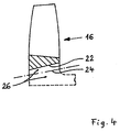
- FIG. 4 shows a partial longitudinal section through a blade unit 16, which is already welded to a joining surface 22 with an intermediate body 26.
- the illustration relates to a variant of the method in which the intermediate body 26 is first welded to one of the bodies to be joined, in this case the blade unit 16, and later to the second body to be connected, here the rotor base body (not shown).
- the intermediate body 26 is adapted by a self-supporting, solid construction to the loads during rotational friction welding. As soon as it is welded to the blade unit 16, a large part of its volume can be removed, for example by turning, the subsequently required joining surface 24 being manufactured, see the part of the intermediate body 26 below the dot-dashed joining surface 24 shown in dashed lines.
- the joining surfaces 22 and 24 may have the same cone direction and optionally the same cone angle. As a result, the joining surfaces 22 and 24 can move radially very close together so that weight and radial height can be saved with respect to the rotor to be produced.
- This time-consuming process variant with two separate Rotationsreibsch divorticiann and intermediate processing has the advantage that the separate welding of the intermediate body 26 with the usually forged rotor body on the one hand and with the usually cast blades on the other hand technically easier to control, since the process parameters are chosen differently thus can be better optimized.
- rotor 10 according to the invention and the method according to the invention can also be used with cooled rotors.
- rotor base body 12 and blade unit 16 have suitable cooling channels 50 (see FIG. 1 ).
- the intermediate body 26 also has, however, somewhat larger, cooling channels 52 in order to connect the channels 50 with each other regardless of its depth of immersion into the gap 20 in any case.
- the intermediate body would then have parallel, axial joining surfaces, wherein its radial thickness would have to be slightly larger for generating a contact pressure, as the radial gap width
Landscapes
- Engineering & Computer Science (AREA)
- Mechanical Engineering (AREA)
- Ceramic Engineering (AREA)
- General Engineering & Computer Science (AREA)
- Pressure Welding/Diffusion-Bonding (AREA)
- Turbine Rotor Nozzle Sealing (AREA)
Claims (11)
- Procédé de fabrication d'un rotor (10) à aubage d'un seul tenant, en particulier d'un rotor de turbine à gaz, avec un corps de base (12) du rotor et une unité d'aubage (16), le corps de base (12) du rotor et l'unité d'aubage (16) étant assemblés au moyen d'un corps intermédiaire (26) par soudage par friction rotative, le corps de base (12) du rotor et l'unité d'aubage (16) étant fabriqués avec des matériaux différents,A) le corps de base (12) du rotor et l'unité d'aubage (16) étant positionnés avec une fente (20) radiale, le corps intermédiaire (26) étant positionné en alignement coaxial par rapport à la fente (20), et ce dernier (26) étant inséré dans la fente (20) par déplacement axial et rotatoire des pièces (12, 16) à assembler par rapport au corps intermédiaire (26) tout en étant simultanément soudé aux pièces (12, 16) à assembler ouB) respectivement par déplacement axial et rotatoire, le corps intermédiaire (26) étant d'abord soudé à une première (12 ou 16) des pièces à assembler avant d'être soudé à la deuxième (16 ou 12) des pièces à assembler en tant qu'unité intégrée à cette pièce (12 ou 16),
caractérisé en ce que les surfaces d'assemblage (22, 24) du corps de base (12) du rotor et de l'unité d'aubage (16) qui définissent la fente (20) sont inclinées symétriquement par rapport à la direction axiale. - Procédé selon la revendication 1, caractérisé en ce que le corps intermédiaire (26) est tourné et axialement inséré dans la fente (20), pour être soudé par friction au corps de base (12) du rotor et à l'unité d'aubage (16).
- Procédé selon la revendication 1 ou 2, caractérisé en ce que la fente (20) se rétrécit dans la direction d'avance (Z) du corps intermédiaire (26), ou s'étend constamment et radialement légèrement inférieure au corps intermédiaire.
- Procédé selon l'une des revendications précédentes, caractérisé en ce que la fente (20) se rétrécit en forme de cône, d'onde ou d'escalier dans la direction d'avance.
- Procédé selon l'une des revendications précédentes, caractérisé en ce que le corps intermédiaire (26) présente une géométrie ajustée à la géométrie de fente, correspondant en particulier à la geométrie de fente.
- Procédé selon l'une des revendications précédentes, caractérisé en ce que l'unité d'aubage (16) est une couronne d'aubes fermée.
- Procécé selon l'une des revendications précédentes, caractérisé en ce que le corps intermédiaire (26) est constitué de matériaux différents sur ses surfaces d'assemblage opposées.
- Procédé selon l'une des revendications précédentes, caractérisé en ce que l'unité d'aubage (16) est maintenue dans une position fixe par correspondance de forme dans un dispositif en cours de soudage.
- Procédé selon l'une des revendications précédentes, caractérisé en ce que l'unité d'aubage (16) présente une surface d'assemblage (22) définissant conjointement la fente (20), et est au moins partiellement recristallisée dans cette zone.
- Procédé selon l'une des revendications précédentes, caractérisé en ce que le corps intermédiaire (26) d'abord réalisé comme corps intermédiaire autoportant adapté aux contraintes du soudage rotatif est, après soudage à une première (12 ou 16) des pièces à assembler et avant soudage à la deuxième (16 ou 12) des pièces à assembler, partiellement érodé, préférentiellement pour plus de 50% de son volume, et en ce qu'une surface d'assemblage (22 ou 24) encore nécessitée est alors réalisée.
- Rotor à aubage d'un seul tenant, en particulier rotor de turbine à gaz, fabriqué selon l'une des revendications 1 à 10, avec un corps de base (12) du rotor et une unité d'aubage (16), le corps de base (12) du rotor et l'unité d'aubage (16) étant assemblés au moyen d'un corps intermédiaire (26) par soudage par friction rotative, le corps de base (12) du rotor et l'unité d'aubage (16) étant fabriqués avec des matériaux différents, et caractérisé en ce que les surfaces d'assemblage (22, 24) du corps de base (12) du rotor et de l'unité d'aubage (16) sont inclinées asymétriquement par rapport à la direction axiale.
Applications Claiming Priority (2)
| Application Number | Priority Date | Filing Date | Title |
|---|---|---|---|
| DE102009013401A DE102009013401A1 (de) | 2009-03-16 | 2009-03-16 | Verfahren zum Herstellen eines integral beschaufelten Rotors, Rotor sowie Vorrichtung zur Durchführung des Verfahrens |
| PCT/DE2010/000268 WO2010105596A1 (fr) | 2009-03-16 | 2010-03-15 | Procédé de fabrication d'un rotor à aubage d'un seul tenant, rotor et dispositif pour mettre en œuvre le procédé |
Publications (2)
| Publication Number | Publication Date |
|---|---|
| EP2408584A1 EP2408584A1 (fr) | 2012-01-25 |
| EP2408584B1 true EP2408584B1 (fr) | 2013-12-18 |
Family
ID=42342731
Family Applications (1)
| Application Number | Title | Priority Date | Filing Date |
|---|---|---|---|
| EP10716270.3A Not-in-force EP2408584B1 (fr) | 2009-03-16 | 2010-03-15 | Procédé de fabrication d'un rotor à aubage d'un seul tenant, rotor et dispositif pour mettre en uvre le procédé |
Country Status (3)
| Country | Link |
|---|---|
| EP (1) | EP2408584B1 (fr) |
| DE (1) | DE102009013401A1 (fr) |
| WO (1) | WO2010105596A1 (fr) |
Families Citing this family (1)
| Publication number | Priority date | Publication date | Assignee | Title |
|---|---|---|---|---|
| CN112496685A (zh) * | 2020-11-27 | 2021-03-16 | 中国航发四川燃气涡轮研究院 | 一种整体叶盘的制造方法 |
Family Cites Families (5)
| Publication number | Priority date | Publication date | Assignee | Title |
|---|---|---|---|---|
| DE2209473A1 (de) * | 1972-02-29 | 1973-09-06 | Audi Nsu Auto Union Ag | Verfahren zur befestigung eines hohlrades an dem mehreckigen kolben einer rotationskolbenmaschine in trochoidenbauart |
| DE102005019356A1 (de) * | 2005-03-03 | 2006-09-07 | Mtu Aero Engines Gmbh | Verfahren zum Fügen von Bauteilen |
| DE102005026505A1 (de) * | 2005-06-09 | 2006-12-14 | Schaeffler Kg | Verfahren zum Verbinden von zwei Bauelementen mittels Reibschweißen sowie Schweißverbindung |
| FR2903921B1 (fr) * | 2006-07-19 | 2009-06-05 | Snecma Sa | Procede de fabrication d'un disque aubage monobloc et moule pour la mise en oeuvre du procede |
| DE102007036972A1 (de) * | 2007-08-04 | 2009-02-05 | Mtu Aero Engines Gmbh | Verfahren zum Fügen sowie Fügeverbindung von zwei Bauteilen aus Metallwerkstoff |
-
2009
- 2009-03-16 DE DE102009013401A patent/DE102009013401A1/de not_active Withdrawn
-
2010
- 2010-03-15 EP EP10716270.3A patent/EP2408584B1/fr not_active Not-in-force
- 2010-03-15 WO PCT/DE2010/000268 patent/WO2010105596A1/fr active Application Filing
Also Published As
| Publication number | Publication date |
|---|---|
| WO2010105596A1 (fr) | 2010-09-23 |
| EP2408584A1 (fr) | 2012-01-25 |
| DE102009013401A1 (de) | 2010-09-23 |
Similar Documents
| Publication | Publication Date | Title |
|---|---|---|
| EP2215329B1 (fr) | Processus de fabrication d'un rotor | |
| WO2009049596A1 (fr) | Procédé de production de blisk ou de bling, élément ainsi obtenu et aube de turbine | |
| EP3299117B1 (fr) | Procédé de fabrication ou de réparation d'un composant d'une machine tournante et composant produit ou réparé selon un tel procédé | |
| EP3251787A1 (fr) | Procédé de fabrication d'un composant de machine rotative et composant fabriqué selon un tel procédé | |
| EP2226146A1 (fr) | Procédé d'assemblage de deux pièces métalliques, notamment symétriques de révolution, par soudage TIG et appareil pour la mise en oeuvre d'un tel procédé | |
| DE102016113289A1 (de) | FSW-Werkzeug mit fester Schulter | |
| EP2366870A2 (fr) | Rotor d'un turbochargeur | |
| EP3501721A1 (fr) | Procédé d'assemblage des composants ainsi que dispositif | |
| DE102005026505A1 (de) | Verfahren zum Verbinden von zwei Bauelementen mittels Reibschweißen sowie Schweißverbindung | |
| EP2408584B1 (fr) | Procédé de fabrication d'un rotor à aubage d'un seul tenant, rotor et dispositif pour mettre en uvre le procédé | |
| EP2219819B1 (fr) | Procédé de fabrication d'un rotor à aubage intégral | |
| DE102012202272B4 (de) | Rotor einer Ladeeinrichtung und Ladeeinrichtung | |
| DE102013216354B4 (de) | Verfahren zur Herstellung eines Leitschaufelkranzes und Leitschaufelkranz | |
| EP2399006B1 (fr) | Procédé de fabrication d'un roteur ayant des aubes et roteur | |
| EP2404036A1 (fr) | Procédé de fabrication d'un rotor aubagé monobloc | |
| EP1008722B1 (fr) | Procédé de fabrication par soudage d'un rotor de turbomachine | |
| DE102009043184A1 (de) | Verfahren zur Reparatur eines integralen Rotors und integraler Rotor | |
| DE102006061448B4 (de) | Verfahren zur Herstellung einer Blisk oder eines Blings einer Gasturbine und danach hergestelltes Bauteil | |
| WO2014146997A1 (fr) | Procédé génératif servant en particulier à fabriquer un revêtement, dispositif servant à la mise en œuvre dudit procédé, revêtement et procédé de production de composant ainsi que composant | |
| EP2870322B1 (fr) | Procédé et dispositif d'assemblage d'une roue de turbine et d'une pièce intercalaire | |
| EP3508690A1 (fr) | Pale de turbine, aube de turbine et leur procédé de fabrication | |
| EP3254806A1 (fr) | Procédé de fabrication d'un appareil de dressage pour un outil de meulage | |
| DE102009004926A1 (de) | Schaufelintegrierte geteilte Scheibe einer Turbinen- oder Verdichterstufe | |
| WO2022171240A1 (fr) | Procédé de production d'une structure d'écoulement pour une turbomachine | |
| WO2020254019A1 (fr) | Structure de support, produit-programme informatique et procédé pour retirer cette structure de support |
Legal Events
| Date | Code | Title | Description |
|---|---|---|---|
| PUAI | Public reference made under article 153(3) epc to a published international application that has entered the european phase |
Free format text: ORIGINAL CODE: 0009012 |
|
| 17P | Request for examination filed |
Effective date: 20110808 |
|
| AK | Designated contracting states |
Kind code of ref document: A1 Designated state(s): AT BE BG CH CY CZ DE DK EE ES FI FR GB GR HR HU IE IS IT LI LT LU LV MC MK MT NL NO PL PT RO SE SI SK SM TR |
|
| DAX | Request for extension of the european patent (deleted) | ||
| GRAP | Despatch of communication of intention to grant a patent |
Free format text: ORIGINAL CODE: EPIDOSNIGR1 |
|
| INTG | Intention to grant announced |
Effective date: 20130906 |
|
| RAP1 | Party data changed (applicant data changed or rights of an application transferred) |
Owner name: MTU AERO ENGINES AG |
|
| GRAS | Grant fee paid |
Free format text: ORIGINAL CODE: EPIDOSNIGR3 |
|
| GRAA | (expected) grant |
Free format text: ORIGINAL CODE: 0009210 |
|
| AK | Designated contracting states |
Kind code of ref document: B1 Designated state(s): AT BE BG CH CY CZ DE DK EE ES FI FR GB GR HR HU IE IS IT LI LT LU LV MC MK MT NL NO PL PT RO SE SI SK SM TR |
|
| REG | Reference to a national code |
Ref country code: GB Ref legal event code: FG4D Free format text: NOT ENGLISH |
|
| REG | Reference to a national code |
Ref country code: CH Ref legal event code: EP |
|
| REG | Reference to a national code |
Ref country code: AT Ref legal event code: REF Ref document number: 645394 Country of ref document: AT Kind code of ref document: T Effective date: 20140115 |
|
| REG | Reference to a national code |
Ref country code: IE Ref legal event code: FG4D Free format text: LANGUAGE OF EP DOCUMENT: GERMAN |
|
| REG | Reference to a national code |
Ref country code: DE Ref legal event code: R096 Ref document number: 502010005706 Country of ref document: DE Effective date: 20140213 |
|
| REG | Reference to a national code |
Ref country code: NL Ref legal event code: VDEP Effective date: 20131218 |
|
| PG25 | Lapsed in a contracting state [announced via postgrant information from national office to epo] |
Ref country code: HR Free format text: LAPSE BECAUSE OF FAILURE TO SUBMIT A TRANSLATION OF THE DESCRIPTION OR TO PAY THE FEE WITHIN THE PRESCRIBED TIME-LIMIT Effective date: 20131218 Ref country code: LT Free format text: LAPSE BECAUSE OF FAILURE TO SUBMIT A TRANSLATION OF THE DESCRIPTION OR TO PAY THE FEE WITHIN THE PRESCRIBED TIME-LIMIT Effective date: 20131218 Ref country code: NO Free format text: LAPSE BECAUSE OF FAILURE TO SUBMIT A TRANSLATION OF THE DESCRIPTION OR TO PAY THE FEE WITHIN THE PRESCRIBED TIME-LIMIT Effective date: 20140318 Ref country code: SE Free format text: LAPSE BECAUSE OF FAILURE TO SUBMIT A TRANSLATION OF THE DESCRIPTION OR TO PAY THE FEE WITHIN THE PRESCRIBED TIME-LIMIT Effective date: 20131218 Ref country code: FI Free format text: LAPSE BECAUSE OF FAILURE TO SUBMIT A TRANSLATION OF THE DESCRIPTION OR TO PAY THE FEE WITHIN THE PRESCRIBED TIME-LIMIT Effective date: 20131218 |
|
| REG | Reference to a national code |
Ref country code: LT Ref legal event code: MG4D |
|
| PG25 | Lapsed in a contracting state [announced via postgrant information from national office to epo] |
Ref country code: LV Free format text: LAPSE BECAUSE OF FAILURE TO SUBMIT A TRANSLATION OF THE DESCRIPTION OR TO PAY THE FEE WITHIN THE PRESCRIBED TIME-LIMIT Effective date: 20131218 |
|
| PG25 | Lapsed in a contracting state [announced via postgrant information from national office to epo] |
Ref country code: IS Free format text: LAPSE BECAUSE OF FAILURE TO SUBMIT A TRANSLATION OF THE DESCRIPTION OR TO PAY THE FEE WITHIN THE PRESCRIBED TIME-LIMIT Effective date: 20140418 Ref country code: EE Free format text: LAPSE BECAUSE OF FAILURE TO SUBMIT A TRANSLATION OF THE DESCRIPTION OR TO PAY THE FEE WITHIN THE PRESCRIBED TIME-LIMIT Effective date: 20131218 |
|
| PG25 | Lapsed in a contracting state [announced via postgrant information from national office to epo] |
Ref country code: RO Free format text: LAPSE BECAUSE OF FAILURE TO SUBMIT A TRANSLATION OF THE DESCRIPTION OR TO PAY THE FEE WITHIN THE PRESCRIBED TIME-LIMIT Effective date: 20131218 Ref country code: ES Free format text: LAPSE BECAUSE OF FAILURE TO SUBMIT A TRANSLATION OF THE DESCRIPTION OR TO PAY THE FEE WITHIN THE PRESCRIBED TIME-LIMIT Effective date: 20131218 Ref country code: CZ Free format text: LAPSE BECAUSE OF FAILURE TO SUBMIT A TRANSLATION OF THE DESCRIPTION OR TO PAY THE FEE WITHIN THE PRESCRIBED TIME-LIMIT Effective date: 20131218 Ref country code: PL Free format text: LAPSE BECAUSE OF FAILURE TO SUBMIT A TRANSLATION OF THE DESCRIPTION OR TO PAY THE FEE WITHIN THE PRESCRIBED TIME-LIMIT Effective date: 20131218 Ref country code: NL Free format text: LAPSE BECAUSE OF FAILURE TO SUBMIT A TRANSLATION OF THE DESCRIPTION OR TO PAY THE FEE WITHIN THE PRESCRIBED TIME-LIMIT Effective date: 20131218 Ref country code: SK Free format text: LAPSE BECAUSE OF FAILURE TO SUBMIT A TRANSLATION OF THE DESCRIPTION OR TO PAY THE FEE WITHIN THE PRESCRIBED TIME-LIMIT Effective date: 20131218 Ref country code: PT Free format text: LAPSE BECAUSE OF FAILURE TO SUBMIT A TRANSLATION OF THE DESCRIPTION OR TO PAY THE FEE WITHIN THE PRESCRIBED TIME-LIMIT Effective date: 20140418 Ref country code: CY Free format text: LAPSE BECAUSE OF FAILURE TO SUBMIT A TRANSLATION OF THE DESCRIPTION OR TO PAY THE FEE WITHIN THE PRESCRIBED TIME-LIMIT Effective date: 20131218 |
|
| REG | Reference to a national code |
Ref country code: DE Ref legal event code: R097 Ref document number: 502010005706 Country of ref document: DE |
|
| PLBE | No opposition filed within time limit |
Free format text: ORIGINAL CODE: 0009261 |
|
| STAA | Information on the status of an ep patent application or granted ep patent |
Free format text: STATUS: NO OPPOSITION FILED WITHIN TIME LIMIT |
|
| PG25 | Lapsed in a contracting state [announced via postgrant information from national office to epo] |
Ref country code: LU Free format text: LAPSE BECAUSE OF FAILURE TO SUBMIT A TRANSLATION OF THE DESCRIPTION OR TO PAY THE FEE WITHIN THE PRESCRIBED TIME-LIMIT Effective date: 20140315 Ref country code: DK Free format text: LAPSE BECAUSE OF FAILURE TO SUBMIT A TRANSLATION OF THE DESCRIPTION OR TO PAY THE FEE WITHIN THE PRESCRIBED TIME-LIMIT Effective date: 20131218 |
|
| REG | Reference to a national code |
Ref country code: CH Ref legal event code: PL |
|
| 26N | No opposition filed |
Effective date: 20140919 |
|
| REG | Reference to a national code |
Ref country code: IE Ref legal event code: MM4A Ref country code: DE Ref legal event code: R097 Ref document number: 502010005706 Country of ref document: DE Effective date: 20140919 |
|
| PG25 | Lapsed in a contracting state [announced via postgrant information from national office to epo] |
Ref country code: CH Free format text: LAPSE BECAUSE OF NON-PAYMENT OF DUE FEES Effective date: 20140331 Ref country code: LI Free format text: LAPSE BECAUSE OF NON-PAYMENT OF DUE FEES Effective date: 20140331 Ref country code: IE Free format text: LAPSE BECAUSE OF NON-PAYMENT OF DUE FEES Effective date: 20140315 |
|
| PG25 | Lapsed in a contracting state [announced via postgrant information from national office to epo] |
Ref country code: SI Free format text: LAPSE BECAUSE OF FAILURE TO SUBMIT A TRANSLATION OF THE DESCRIPTION OR TO PAY THE FEE WITHIN THE PRESCRIBED TIME-LIMIT Effective date: 20131218 |
|
| PG25 | Lapsed in a contracting state [announced via postgrant information from national office to epo] |
Ref country code: MT Free format text: LAPSE BECAUSE OF FAILURE TO SUBMIT A TRANSLATION OF THE DESCRIPTION OR TO PAY THE FEE WITHIN THE PRESCRIBED TIME-LIMIT Effective date: 20131218 |
|
| REG | Reference to a national code |
Ref country code: FR Ref legal event code: PLFP Year of fee payment: 7 |
|
| PG25 | Lapsed in a contracting state [announced via postgrant information from national office to epo] |
Ref country code: SM Free format text: LAPSE BECAUSE OF FAILURE TO SUBMIT A TRANSLATION OF THE DESCRIPTION OR TO PAY THE FEE WITHIN THE PRESCRIBED TIME-LIMIT Effective date: 20131218 |
|
| REG | Reference to a national code |
Ref country code: AT Ref legal event code: MM01 Ref document number: 645394 Country of ref document: AT Kind code of ref document: T Effective date: 20150315 |
|
| PG25 | Lapsed in a contracting state [announced via postgrant information from national office to epo] |
Ref country code: MC Free format text: LAPSE BECAUSE OF FAILURE TO SUBMIT A TRANSLATION OF THE DESCRIPTION OR TO PAY THE FEE WITHIN THE PRESCRIBED TIME-LIMIT Effective date: 20131218 |
|
| PG25 | Lapsed in a contracting state [announced via postgrant information from national office to epo] |
Ref country code: BG Free format text: LAPSE BECAUSE OF FAILURE TO SUBMIT A TRANSLATION OF THE DESCRIPTION OR TO PAY THE FEE WITHIN THE PRESCRIBED TIME-LIMIT Effective date: 20131218 Ref country code: GR Free format text: LAPSE BECAUSE OF FAILURE TO SUBMIT A TRANSLATION OF THE DESCRIPTION OR TO PAY THE FEE WITHIN THE PRESCRIBED TIME-LIMIT Effective date: 20140319 Ref country code: IT Free format text: LAPSE BECAUSE OF FAILURE TO SUBMIT A TRANSLATION OF THE DESCRIPTION OR TO PAY THE FEE WITHIN THE PRESCRIBED TIME-LIMIT Effective date: 20131218 |
|
| PG25 | Lapsed in a contracting state [announced via postgrant information from national office to epo] |
Ref country code: TR Free format text: LAPSE BECAUSE OF FAILURE TO SUBMIT A TRANSLATION OF THE DESCRIPTION OR TO PAY THE FEE WITHIN THE PRESCRIBED TIME-LIMIT Effective date: 20131218 Ref country code: HU Free format text: LAPSE BECAUSE OF FAILURE TO SUBMIT A TRANSLATION OF THE DESCRIPTION OR TO PAY THE FEE WITHIN THE PRESCRIBED TIME-LIMIT; INVALID AB INITIO Effective date: 20100315 Ref country code: BE Free format text: LAPSE BECAUSE OF FAILURE TO SUBMIT A TRANSLATION OF THE DESCRIPTION OR TO PAY THE FEE WITHIN THE PRESCRIBED TIME-LIMIT Effective date: 20140331 |
|
| PG25 | Lapsed in a contracting state [announced via postgrant information from national office to epo] |
Ref country code: AT Free format text: LAPSE BECAUSE OF NON-PAYMENT OF DUE FEES Effective date: 20150315 |
|
| REG | Reference to a national code |
Ref country code: FR Ref legal event code: PLFP Year of fee payment: 8 |
|
| REG | Reference to a national code |
Ref country code: FR Ref legal event code: PLFP Year of fee payment: 9 |
|
| PGFP | Annual fee paid to national office [announced via postgrant information from national office to epo] |
Ref country code: DE Payment date: 20180322 Year of fee payment: 9 Ref country code: GB Payment date: 20180326 Year of fee payment: 9 |
|
| PGFP | Annual fee paid to national office [announced via postgrant information from national office to epo] |
Ref country code: FR Payment date: 20180326 Year of fee payment: 9 |
|
| PG25 | Lapsed in a contracting state [announced via postgrant information from national office to epo] |
Ref country code: MK Free format text: LAPSE BECAUSE OF FAILURE TO SUBMIT A TRANSLATION OF THE DESCRIPTION OR TO PAY THE FEE WITHIN THE PRESCRIBED TIME-LIMIT Effective date: 20131218 |
|
| REG | Reference to a national code |
Ref country code: DE Ref legal event code: R119 Ref document number: 502010005706 Country of ref document: DE |
|
| GBPC | Gb: european patent ceased through non-payment of renewal fee |
Effective date: 20190315 |
|
| PG25 | Lapsed in a contracting state [announced via postgrant information from national office to epo] |
Ref country code: GB Free format text: LAPSE BECAUSE OF NON-PAYMENT OF DUE FEES Effective date: 20190315 Ref country code: DE Free format text: LAPSE BECAUSE OF NON-PAYMENT OF DUE FEES Effective date: 20191001 |
|
| PG25 | Lapsed in a contracting state [announced via postgrant information from national office to epo] |
Ref country code: FR Free format text: LAPSE BECAUSE OF NON-PAYMENT OF DUE FEES Effective date: 20190331 |