EP2408553B1 - Package assembly for a structured package - Google Patents
Package assembly for a structured package Download PDFInfo
- Publication number
- EP2408553B1 EP2408553B1 EP10709509.3A EP10709509A EP2408553B1 EP 2408553 B1 EP2408553 B1 EP 2408553B1 EP 10709509 A EP10709509 A EP 10709509A EP 2408553 B1 EP2408553 B1 EP 2408553B1
- Authority
- EP
- European Patent Office
- Prior art keywords
- layer
- wave
- indentations
- indentation
- packing
- Prior art date
- Legal status (The legal status is an assumption and is not a legal conclusion. Google has not performed a legal analysis and makes no representation as to the accuracy of the status listed.)
- Active
Links
- 238000007373 indentation Methods 0.000 claims description 87
- 239000006096 absorbing agent Substances 0.000 claims description 18
- 238000004806 packaging method and process Methods 0.000 claims 2
- 238000012856 packing Methods 0.000 description 79
- 239000007788 liquid Substances 0.000 description 38
- 239000007789 gas Substances 0.000 description 35
- 239000012530 fluid Substances 0.000 description 29
- 238000012546 transfer Methods 0.000 description 26
- 238000010521 absorption reaction Methods 0.000 description 20
- 239000002250 absorbent Substances 0.000 description 16
- 230000002745 absorbent Effects 0.000 description 16
- 238000000926 separation method Methods 0.000 description 13
- 239000002904 solvent Substances 0.000 description 13
- 239000000126 substance Substances 0.000 description 10
- HEMHJVSKTPXQMS-UHFFFAOYSA-M Sodium hydroxide Chemical compound [OH-].[Na+] HEMHJVSKTPXQMS-UHFFFAOYSA-M 0.000 description 9
- 229910052751 metal Inorganic materials 0.000 description 9
- 239000002184 metal Substances 0.000 description 9
- 238000000034 method Methods 0.000 description 9
- 230000008569 process Effects 0.000 description 6
- 239000000243 solution Substances 0.000 description 5
- 238000009736 wetting Methods 0.000 description 5
- KFZMGEQAYNKOFK-UHFFFAOYSA-N Isopropanol Chemical compound CC(C)O KFZMGEQAYNKOFK-UHFFFAOYSA-N 0.000 description 4
- 238000003795 desorption Methods 0.000 description 4
- 239000007791 liquid phase Substances 0.000 description 4
- 238000011068 loading method Methods 0.000 description 4
- 239000000463 material Substances 0.000 description 4
- 239000012071 phase Substances 0.000 description 4
- XLYOFNOQVPJJNP-UHFFFAOYSA-N water Substances O XLYOFNOQVPJJNP-UHFFFAOYSA-N 0.000 description 4
- 238000005452 bending Methods 0.000 description 3
- 238000009835 boiling Methods 0.000 description 3
- 238000013461 design Methods 0.000 description 3
- 239000000945 filler Substances 0.000 description 3
- 238000004519 manufacturing process Methods 0.000 description 3
- 239000004033 plastic Substances 0.000 description 3
- 229920003023 plastic Polymers 0.000 description 3
- HZAXFHJVJLSVMW-UHFFFAOYSA-N 2-Aminoethan-1-ol Chemical compound NCCO HZAXFHJVJLSVMW-UHFFFAOYSA-N 0.000 description 2
- 230000008901 benefit Effects 0.000 description 2
- 239000000919 ceramic Substances 0.000 description 2
- 230000008859 change Effects 0.000 description 2
- 238000004140 cleaning Methods 0.000 description 2
- 230000000694 effects Effects 0.000 description 2
- 238000004049 embossing Methods 0.000 description 2
- 239000007792 gaseous phase Substances 0.000 description 2
- 230000008092 positive effect Effects 0.000 description 2
- 238000003825 pressing Methods 0.000 description 2
- 230000009467 reduction Effects 0.000 description 2
- 238000009827 uniform distribution Methods 0.000 description 2
- KWYUFKZDYYNOTN-UHFFFAOYSA-M Potassium hydroxide Chemical compound [OH-].[K+] KWYUFKZDYYNOTN-UHFFFAOYSA-M 0.000 description 1
- 239000007864 aqueous solution Substances 0.000 description 1
- 230000001174 ascending effect Effects 0.000 description 1
- 230000009286 beneficial effect Effects 0.000 description 1
- 238000006243 chemical reaction Methods 0.000 description 1
- 238000000576 coating method Methods 0.000 description 1
- 230000006835 compression Effects 0.000 description 1
- 238000007906 compression Methods 0.000 description 1
- 238000009833 condensation Methods 0.000 description 1
- 230000005494 condensation Effects 0.000 description 1
- 238000001944 continuous distillation Methods 0.000 description 1
- 238000005260 corrosion Methods 0.000 description 1
- 230000007797 corrosion Effects 0.000 description 1
- 238000009792 diffusion process Methods 0.000 description 1
- 238000002474 experimental method Methods 0.000 description 1
- 230000006872 improvement Effects 0.000 description 1
- 239000000203 mixture Substances 0.000 description 1
- 229940072033 potash Drugs 0.000 description 1
- BWHMMNNQKKPAPP-UHFFFAOYSA-L potassium carbonate Substances [K+].[K+].[O-]C([O-])=O BWHMMNNQKKPAPP-UHFFFAOYSA-L 0.000 description 1
- 235000015320 potassium carbonate Nutrition 0.000 description 1
- 238000012545 processing Methods 0.000 description 1
- 230000001737 promoting effect Effects 0.000 description 1
- 238000000746 purification Methods 0.000 description 1
- 238000010408 sweeping Methods 0.000 description 1
- 238000012360 testing method Methods 0.000 description 1
Images


Classifications
-
- B—PERFORMING OPERATIONS; TRANSPORTING
- B01—PHYSICAL OR CHEMICAL PROCESSES OR APPARATUS IN GENERAL
- B01J—CHEMICAL OR PHYSICAL PROCESSES, e.g. CATALYSIS OR COLLOID CHEMISTRY; THEIR RELEVANT APPARATUS
- B01J19/00—Chemical, physical or physico-chemical processes in general; Their relevant apparatus
- B01J19/32—Packing elements in the form of grids or built-up elements for forming a unit or module inside the apparatus for mass or heat transfer
-
- B—PERFORMING OPERATIONS; TRANSPORTING
- B01—PHYSICAL OR CHEMICAL PROCESSES OR APPARATUS IN GENERAL
- B01D—SEPARATION
- B01D15/00—Separating processes involving the treatment of liquids with solid sorbents; Apparatus therefor
- B01D15/08—Selective adsorption, e.g. chromatography
- B01D15/10—Selective adsorption, e.g. chromatography characterised by constructional or operational features
- B01D15/22—Selective adsorption, e.g. chromatography characterised by constructional or operational features relating to the construction of the column
-
- B—PERFORMING OPERATIONS; TRANSPORTING
- B01—PHYSICAL OR CHEMICAL PROCESSES OR APPARATUS IN GENERAL
- B01D—SEPARATION
- B01D3/00—Distillation or related exchange processes in which liquids are contacted with gaseous media, e.g. stripping
- B01D3/14—Fractional distillation or use of a fractionation or rectification column
-
- B—PERFORMING OPERATIONS; TRANSPORTING
- B01—PHYSICAL OR CHEMICAL PROCESSES OR APPARATUS IN GENERAL
- B01D—SEPARATION
- B01D53/00—Separation of gases or vapours; Recovering vapours of volatile solvents from gases; Chemical or biological purification of waste gases, e.g. engine exhaust gases, smoke, fumes, flue gases, aerosols
- B01D53/14—Separation of gases or vapours; Recovering vapours of volatile solvents from gases; Chemical or biological purification of waste gases, e.g. engine exhaust gases, smoke, fumes, flue gases, aerosols by absorption
- B01D53/18—Absorbing units; Liquid distributors therefor
-
- B—PERFORMING OPERATIONS; TRANSPORTING
- B01—PHYSICAL OR CHEMICAL PROCESSES OR APPARATUS IN GENERAL
- B01J—CHEMICAL OR PHYSICAL PROCESSES, e.g. CATALYSIS OR COLLOID CHEMISTRY; THEIR RELEVANT APPARATUS
- B01J19/00—Chemical, physical or physico-chemical processes in general; Their relevant apparatus
-
- B—PERFORMING OPERATIONS; TRANSPORTING
- B01—PHYSICAL OR CHEMICAL PROCESSES OR APPARATUS IN GENERAL
- B01J—CHEMICAL OR PHYSICAL PROCESSES, e.g. CATALYSIS OR COLLOID CHEMISTRY; THEIR RELEVANT APPARATUS
- B01J2219/00—Chemical, physical or physico-chemical processes in general; Their relevant apparatus
- B01J2219/32—Details relating to packing elements in the form of grids or built-up elements for forming a unit of module inside the apparatus for mass or heat transfer
- B01J2219/322—Basic shape of the elements
- B01J2219/32203—Sheets
- B01J2219/3221—Corrugated sheets
-
- B—PERFORMING OPERATIONS; TRANSPORTING
- B01—PHYSICAL OR CHEMICAL PROCESSES OR APPARATUS IN GENERAL
- B01J—CHEMICAL OR PHYSICAL PROCESSES, e.g. CATALYSIS OR COLLOID CHEMISTRY; THEIR RELEVANT APPARATUS
- B01J2219/00—Chemical, physical or physico-chemical processes in general; Their relevant apparatus
- B01J2219/32—Details relating to packing elements in the form of grids or built-up elements for forming a unit of module inside the apparatus for mass or heat transfer
- B01J2219/322—Basic shape of the elements
- B01J2219/32203—Sheets
- B01J2219/32213—Plurality of essentially parallel sheets
-
- B—PERFORMING OPERATIONS; TRANSPORTING
- B01—PHYSICAL OR CHEMICAL PROCESSES OR APPARATUS IN GENERAL
- B01J—CHEMICAL OR PHYSICAL PROCESSES, e.g. CATALYSIS OR COLLOID CHEMISTRY; THEIR RELEVANT APPARATUS
- B01J2219/00—Chemical, physical or physico-chemical processes in general; Their relevant apparatus
- B01J2219/32—Details relating to packing elements in the form of grids or built-up elements for forming a unit of module inside the apparatus for mass or heat transfer
- B01J2219/322—Basic shape of the elements
- B01J2219/32203—Sheets
- B01J2219/32224—Sheets characterised by the orientation of the sheet
- B01J2219/32227—Vertical orientation
-
- B—PERFORMING OPERATIONS; TRANSPORTING
- B01—PHYSICAL OR CHEMICAL PROCESSES OR APPARATUS IN GENERAL
- B01J—CHEMICAL OR PHYSICAL PROCESSES, e.g. CATALYSIS OR COLLOID CHEMISTRY; THEIR RELEVANT APPARATUS
- B01J2219/00—Chemical, physical or physico-chemical processes in general; Their relevant apparatus
- B01J2219/32—Details relating to packing elements in the form of grids or built-up elements for forming a unit of module inside the apparatus for mass or heat transfer
- B01J2219/322—Basic shape of the elements
- B01J2219/32203—Sheets
- B01J2219/32248—Sheets comprising areas that are raised or sunken from the plane of the sheet
-
- B—PERFORMING OPERATIONS; TRANSPORTING
- B01—PHYSICAL OR CHEMICAL PROCESSES OR APPARATUS IN GENERAL
- B01J—CHEMICAL OR PHYSICAL PROCESSES, e.g. CATALYSIS OR COLLOID CHEMISTRY; THEIR RELEVANT APPARATUS
- B01J2219/00—Chemical, physical or physico-chemical processes in general; Their relevant apparatus
- B01J2219/32—Details relating to packing elements in the form of grids or built-up elements for forming a unit of module inside the apparatus for mass or heat transfer
- B01J2219/322—Basic shape of the elements
- B01J2219/32203—Sheets
- B01J2219/32255—Other details of the sheets
-
- B—PERFORMING OPERATIONS; TRANSPORTING
- B01—PHYSICAL OR CHEMICAL PROCESSES OR APPARATUS IN GENERAL
- B01J—CHEMICAL OR PHYSICAL PROCESSES, e.g. CATALYSIS OR COLLOID CHEMISTRY; THEIR RELEVANT APPARATUS
- B01J2219/00—Chemical, physical or physico-chemical processes in general; Their relevant apparatus
- B01J2219/32—Details relating to packing elements in the form of grids or built-up elements for forming a unit of module inside the apparatus for mass or heat transfer
- B01J2219/324—Composition or microstructure of the elements
- B01J2219/32408—Metal
- B01J2219/32416—Metal fibrous
-
- B—PERFORMING OPERATIONS; TRANSPORTING
- B01—PHYSICAL OR CHEMICAL PROCESSES OR APPARATUS IN GENERAL
- B01J—CHEMICAL OR PHYSICAL PROCESSES, e.g. CATALYSIS OR COLLOID CHEMISTRY; THEIR RELEVANT APPARATUS
- B01J2219/00—Chemical, physical or physico-chemical processes in general; Their relevant apparatus
- B01J2219/32—Details relating to packing elements in the form of grids or built-up elements for forming a unit of module inside the apparatus for mass or heat transfer
- B01J2219/324—Composition or microstructure of the elements
- B01J2219/32425—Ceramic
-
- B—PERFORMING OPERATIONS; TRANSPORTING
- B01—PHYSICAL OR CHEMICAL PROCESSES OR APPARATUS IN GENERAL
- B01J—CHEMICAL OR PHYSICAL PROCESSES, e.g. CATALYSIS OR COLLOID CHEMISTRY; THEIR RELEVANT APPARATUS
- B01J2219/00—Chemical, physical or physico-chemical processes in general; Their relevant apparatus
- B01J2219/32—Details relating to packing elements in the form of grids or built-up elements for forming a unit of module inside the apparatus for mass or heat transfer
- B01J2219/324—Composition or microstructure of the elements
- B01J2219/32483—Plastics
-
- B—PERFORMING OPERATIONS; TRANSPORTING
- B01—PHYSICAL OR CHEMICAL PROCESSES OR APPARATUS IN GENERAL
- B01J—CHEMICAL OR PHYSICAL PROCESSES, e.g. CATALYSIS OR COLLOID CHEMISTRY; THEIR RELEVANT APPARATUS
- B01J2219/00—Chemical, physical or physico-chemical processes in general; Their relevant apparatus
- B01J2219/32—Details relating to packing elements in the form of grids or built-up elements for forming a unit of module inside the apparatus for mass or heat transfer
- B01J2219/324—Composition or microstructure of the elements
- B01J2219/32491—Woven or knitted materials
Definitions
- the invention relates to a structured packing and a mass transfer apparatus which contains such a structured packing, for example an absorption column or a desorption column.
- structured packings are designed as folded sheets of metal arranged one behind the other, the structure of which has inclined and repeatedly intersecting channels. These channels have a positive effect on the flow of gas and liquid phases within the packing and promote the transport of substances between the phases. This means that the gas and liquid phases are brought into contact in the channels of the packing, thus promoting the transport of substances between the phases.
- the surface of the structured packing is usually enlarged, which is mostly achieved by a higher number of layers and / or narrower channel geometries.
- these measures lead to an increase in the pressure drop in the structured packing. It follows from this, however, that less packing surface has to be provided in order to reduce the pressure drop, as a result of which the separation performance deteriorates, that is to say the efficiency of the packing.
- more open intersection channels can be provided. More open intersection channels means that the The angle of inclination of the channels is selected to be lower in relation to the main flow direction. This means that, depending on the application, an optimum must be found between pressure drop and the best possible separation performance.
- the intersecting channels have many contact points, which in some applications can have a positive effect in other applications.
- the height of the wave crests or edges is varied in such a way that only some of the wave crests or edges of each sheet metal have the maximum height.
- the sheets therefore only touch one another along the corrugation crests or edges with maximum height.
- a disadvantage of the packing proposed according to US Pat. No. 6,378,332 B1 is its inadequate mechanical stability.
- that will go through the volume filled up with the packing is not optimally filled with a geometric exchange surface because of the folds that are sometimes less high, that is to say this structural configuration is associated with a loss of mass exchange surface.
- a contact body in which a first and second layer of a structured packing, which have a wave-like profile, are arranged one above the other in such a way that the channels that are formed by the wave-like profiles cross.
- the wave-like profile of the layers always has sharp edges.
- the object of the invention is therefore to provide a structured packing which has improved stability with the same or a smaller number of contact points.
- Another object of the invention is to improve the mass transfer, in particular in an absorber or desorber that is controlled on the liquid side.
- the solution consists in an absorber or desorber according to claim 1.
- This contains a first layer for a structured packing.
- the first layer for the structured packing has a first wave-like profile, a plurality of open channels being formed by the wave-like profile.
- the channels comprise a first wave trough, a first wave crest and a second wave crest, the first wave crest and the second wave crest delimiting the first wave trough, the first and the second wave crest having a first rounded apex and have a second rounded vertex.
- An indentation extending in the direction of the first apex is formed on the first apex of the first crest, the first corrugation valley having a rounded valley floor, the normal distance of at least one point of the indentation to the valley floor of the wave valley being smaller than the normal distance of the first apex to the valley floor of the wave valley.
- a second indentation (44) is arranged on the second apex and a third indentation is arranged on the valley floor, the first, second and third indentations being designed as lenticular indentations.
- the depth of each indentation is in the range from 10 to 30% of the layer height, so that there are gaps between the individual packing layers of precisely this range of values.
- a second layer is provided, the second layer having a second wave-like profile, the first layer and the second layer being arranged in such a way that the channels of the first layer intersect with the channels of the second layer.
- the first layer is in touching contact with the second layer, the touching contact being interrupted in the area of each of the indentations.
- the indentations thus create an additional possibility for guiding the liquid flow, as well as an arrangement the contact points, which enables maximum liquid wetting of the packing surface.
- a second indentation is arranged on the second apex and a third indentation is arranged on the first valley floor.
- a plurality of first, second or third indentations can be provided on the layer.
- Each layer can comprise a first edge delimitation and a second edge delimitation, the first edge delimitation being arranged essentially parallel to the second edge delimitation.
- a plurality of indentations can be arranged between the first edge delimitation and the second edge delimitation.
- the layer has a wave-like profile, the wave height being essentially constant.
- At least some of the vertices are formed as an edge and / or at least some of the wave troughs are V-shaped.
- a structured packing thus comprises a first layer according to one of the preceding exemplary embodiments and a second layer, the second layer having a wave-like profile like the first layer, the first layer and the second layer being arranged such that the channels of the first layer are arranged cross with the channels of the second layer.
- the first layer is in touching contact with the second layer, preferably in that the crests of the wave crests of the first layer and the crests of the wave troughs of the second layer touch one another.
- the indentations can be arranged on each of the first and second layers.
- the contact of the first layer with the second layer is interrupted by the indentations.
- a pack according to the invention consists of structured layers, the folds of which are all of the same height. This ensures a high stability of the packing, which is particularly important in columns with a large diameter.
- the number of intersection points of the individual layers is reduced by making indentations. These indentations are designed as lens-shaped dents which can be made, for example, by plastic deformation of the apex of the layer. The indentations are applied to the folded packing layers at specific points and thus the packing layers can be separated from one another at a defined distance and at defined points.
- the indentations in the packing layer could be designed by providing a cavity in which an insert element can be attached.
- the indentations can extend over a length which is up to 75% of the length of the apex.
- the indentation is advantageously arranged within at least one of the first or second edge delimitations, so that the edge region is designed for increased dimensional stability of the pack.
- Each of the indentations can be interrupted by an elevation.
- the indentations of the first layer can be arranged at least partially overlapping with the indentations of the second layer.
- the indentation can comprise an intermediate elevation, in particular if the indentation extends by up to 75% of the length of the apex.
- the intermediate elevation can rest on the apex of the adjacent layer or be arranged at a distance from the same.
- Each of the layers can contain an opening. Such an opening can facilitate the passage of gas and / or liquid to an adjacent layer. Such openings can be in the wall area of the fold on the The crests of the wave crests or troughs or also be arranged in the area of the indentations.
- the indentation is produced together with the production of the layer by means of a forming process.
- the production of the layer can thus take place with a minimal number of process steps.
- the indentations can be worked out of the sheet metal at defined points, e.g. on the upper and lower edge of the pack layer, by pressing, embossing or deep drawing.
- the channels do not touch each other in the area of the indentations.
- a crest can be understood to mean both a wave crest and an edge, that is to say a tip that is formed by two adjacent side surfaces of a channel.
- the mass transfer takes place in several sequential partial steps.
- the components contained in the gas that have to be separated are transported to the interface with the liquid by convection and diffusion.
- the components then have to pass the interface and be absorbed in the liquid. So that the mass transfer can be improved, it is advantageous to provide the largest possible mass transfer surface for the liquid.
- Another object of the invention is to select the arrangement of the contact points in such a way that the contact points result in a minimal change in the exchange of substances.
- the contact points are increasingly arranged in the edge region of the first layer.
- this uniform distribution of the contact points over the surface of the pack can be dispensed with in the invention. If the few contact points are thus placed closer together, the flow constriction causes a backflow behind the contact points, whereby the unwetted area behind the contact point is reduced. As a result, there are fewer contact points with less unwetted area and, in total, a minimal ratio of unwetted to total pack surface.
- each of the layers there are a plurality of indentations on each of the layers.
- all layers have the same structure, which reduces manufacturing costs.
- the layers can be produced continuously in this form by continuously folding a band, during which the indentations are also produced.
- the folded and indented tape is cut to the desired dimensions.
- the cut tape parts result in the layers, with every other layer being turned so that a cross-wise arrangement of layers is created when they are placed one on top of the other next to one another.
- a mass transfer apparatus in particular a column, can comprise a structured packing according to one of the preceding claims.
- a method for cleaning fluids in a mass transfer apparatus which contains a structured packing comprises the steps: supplying a less volatile fluid to the mass transfer apparatus, distributing the supplied less volatile fluid over the surface of the packing, supplying a more volatile fluid into the mass transfer apparatus a fluid inlet area, distributing the more volatile fluid in the gas inlet area over the surface of the packing, the more volatile fluid flowing in countercurrent to the liquid, collecting the more volatile fluid that leaves the packing in a fluid outlet area, the structured packing having a first layer and a contains second layer, wherein the first layer and the second layer have a wave-like profile with constant wave height, wherein open channels are formed by the wave-like profile, the channels of the first layer intersect with the channels of the second layer, the more volatile fluid flows through the channels from the fluid inlet area in the direction of the fluid outlet area, the less volatile fluid surrounding the more volatile fluid flowing through the channels and flowing along the channel walls.
- the first layer is in touching contact with the second layer via the apex of the wave crests, so that a mass transfer
- indentations and an arrangement of the contact points enables maximum liquid wetting of the packing surface in mass transfer devices.
- the pack preferably consists of structured layers, the folds of which are all of the same height. This creates a high stability of the packing, which is particularly important in columns with a large diameter.
- the number of intersection points between the individual layers is reduced by making indentations at the apexes of wave crests at least one of two adjacent layers.
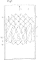
- Fig. 1 shows a device 1 comprising several layers of a structured packing 7, which form a packing body.
- Structured packing 7 is understood to mean a means for mass transfer between two fluid phases.
- the structured packing 7 is used in a mass transfer apparatus 2.
- the mass transfer apparatus can in particular be designed as a column 5 which can be used for absorption or desorption.
- the structured packing 7 consists of a plurality of layers which are in a regularly repeating geometric relationship to one another.
- the distance between adjacent layers can be chosen as an example of this geometric relationship. According to the geometric relationship, the distances between adjacent layers can periodically assume the same value, so that the sum of the layers creates a structure that is characterized by the same or at least periodically equal distances.
- the periodicity is found in the entire structured packing, which gives the packing a regular structure.
- the structure can be designed as a wave-like profile.
- bulk fill packs consist of bulk fillers, that is to say of elements of the same geometric structure, but each bulk filler can have any spacing from adjacent bulk fillers, so that a periodicity of these spacings is not recognizable.
- the random packings are introduced into the column as a bed. They form a pile on a column bottom. The pile is characterized by the random arrangement of the individual random packing.
- the locations according to Fig. 1 consist of thin-walled elements that have a wave-like profile.
- the wave-like profile is characterized by a periodically repeating sequence of elevations, i.e. wave crests and valley-like depressions, i.e. wave troughs.
- This wave-like profile can in particular be designed as a fold with a zigzag profile with pointed edges.
- the layers are arranged in relation to one another in such a way that the wave-like profiles of two adjacent layers in are inclined at an angle to the main flow direction.
- the wave-like profiles of adjacent layers are arranged crosswise to one another.
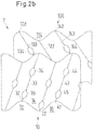
- Fig. 2a shows two adjacent layers 10, 100 of the structured packing 7 according to FIG Fig. 1 .
- a first layer 10 is arranged adjacent to a second layer 100.
- the first layer 10 and the second layer 100 can in particular comprise an element made of sheet metal or metal mesh, but alternatively also comprise elements made of plastic or ceramic.
- An element can encompass the entire layer, or else only form part of it.
- the element can have the shape of a plate which comprises a wave-like profile, in particular a zigzag profile or a wave-like profile with rounded peaks and valley bottoms.
- the element can have coatings made of plastics or ceramics in order to make the resistance of the layer more resistant to chemical influences such as corrosion or thermal influences such as temperature, or mechanical influences such as pressure.
- the first layer 10 and the second layer 100 in FIG Fig. 2a are shown in a view which shows a section of the first surface 8 of the pack 7.
- the first surface 8 of the packing 7 is arranged essentially normal to the main flow direction 6.
- the main flow direction 6 denotes the flow direction in which a more volatile fluid, in particular a gas, flows upward in the column without internals, that is, in the direction of the top of the column 5.
- the opposite direction can also be defined as the main flow direction.
- the main flow direction corresponds to the direction in which a less volatile fluid, that is to say mostly a liquid, flows through the column without internals, that is, in free fall.
- the direction of flow deviates locally from the main flow direction, since the flow is deflected by the layers of the packing.
- the first layer 10 of the structured packing 7 has a wave-like profile, a plurality of open channels 12, 14, 16 being formed by the wave-like profile.
- the channels include a first wave trough 22, a first wave crest 32 and a second wave crest 42.
- the first wave crest 32 and the second wave crest 42 delimit the first wave trough 22.
- the first wave crest 32 and the second wave crest 42 have a first crest 33 and a second crest 43.
- On the second vertex 43 of the second wave crest 42 an indentation 44 extending in the direction of the second vertex 43 is formed.
- the first wave trough 22 has a valley floor 23.
- the first wave trough 22 has a valley floor 23, the normal distance 27 of at least one point of the indentation 34 to the valley floor 23 of the wave trough 22 being smaller than the normal distance of the first apex 33 to the valley floor 23 of the wave trough 22.
- the normal distance between the first apex 33 of the first wave crest 32 and the valley floor 23 of the first wave trough 22 is referred to as wave height 28.
- the wave height 28 is accordingly greater than the normal distance 27.
- the wave height 28 is in particular essentially constant, that is to say it is in the range of the usual tolerances, which are in the range of 0.5 mm.
- a first indentation 34 can also be arranged on the first apex 33.
- a second indentation 24 can also be arranged on the first valley floor 23.
- the second layer 100 of the structured packing 7 has a wave-like profile, a plurality of open channels 112, 114, 116 being formed by the wave-like profile.
- the channels comprise a first wave trough 122, a first wave crest 132 and a second wave crest 142.
- the first wave crest 132 and the second wave crest 142 delimit the first wave trough 122.
- the first wave crest 132 and the second wave crest 142 have a first crest 133 and a second Vertex 143 up.
- An indentation 134 extending in the direction of the first vertex 133 is formed on the first vertex 133 of the first wave crest 132.
- the first wave trough 122 has a valley floor 123.
- the indentation 134 and the indentation 144 have a smaller normal distance from the valley floor 123 of the wave valley 122 than the second vertex 143 of the second wave crest 142 has from the valley floor 123 of the wave valley 122.
- At least a part of the apex can be formed as an edge.
- At least some of the wave troughs can be V-shaped.
- the normal distance between the valley floor and the apex is according to Fig. 2a essentially the same for all wave crests in the position.
- Figure 2b shows two adjacent layers of a structured packing with a wave-like profile, according to which the vertices do not form pointed edges, but are designed as curves. Otherwise, refer to the description of the Fig. 2a referenced.
- Fig. 3 shows the influence of the arrangement of the contact points on the wettability of the surface of a layer, for example the layer 10 of FIG Fig. 2a or Figure 2b shown pack.
- Fig. 3a shows an arrangement according to the prior art.
- the layer 10 covers the layer 100, which is not visible because it lies behind it in the plane of the drawing.
- the first vertex 33, the second vertex 43 and the valley floor 23 lying in between are shown by way of example.
- the first and second vertices 33, 43 and the valley floor 23 form folded edges.
- the vertices 33, 42 rest on the valley floor 123, which belongs to the layer 100.
- each of the layers 10 and the layers 100 each contain a plurality of further peaks and valley bottoms, which are not designated in more detail since they do not differ from the designated peaks and valley bottoms.
- the lines belonging to the peaks of the wave crests are drawn out thicker than the lines belonging to the valley bottoms.
- a long-dashed line is provided for the apex of the wave crests of the second layer 100, as well as a short-dashed line for the valley bottoms of the layer 100.
- Contact points 48 arise at the points where a valley bottom of the layer 10 and an apex of the layer 100 meet , in the Fig. 3 are marked with a circle. In the two layers 10, 100 shown, the contact points are evenly distributed over the entire surface.
- Fig. 3 it can be seen that the contact points are very close to one another, as a result of which there are very many small zones 46 of unwetted surface and thus a relatively large proportion of unwetted surface in relation to the total packing area.
- Fig. 3 is only a single zone 46 shown, the arrows 47 symbolize the flow of the less volatile fluid.
- Fig. 4 shows the case in which the contact points are reduced, for example, by folding the layers, as proposed in US Pat. No. 6,378,332 B1.
- the liquid flows are deflected further in this version.
- the geometrical shape of the layers according to FIG Fig. 4 will be discussed in detail in Figure 8a received.
- Fig. 5 shows an arrangement of the contact points 48 between two adjacent layers 10, 100 according to the invention.
- the layer 100 is arranged behind the layer 10.
- the number of contact points is reduced with respect to the surface of the layer 10. In particular, the contact points are not evenly distributed over the surface.
- the flow constriction causes a backflow behind the contact points, which in turn reduces the unwetted area behind the contact point.
- the layer 10 comprises a first edge delimitation 50 and a second edge delimitation 60, the first edge delimitation 50 being arranged essentially parallel to the second edge delimitation 60.
- the edge delimitation 50 spans an upper boundary surface and the second edge delimitation 60 defines a lower boundary surface.
- the layer 10 comprises a first edge delimitation 51 and a second edge delimitation 61.
- the first edge delimitation 51 and the second edge delimitation 61 run when the layer is oriented vertically in a pack adjacent to the inner wall of the mass transfer apparatus, especially the column. At least one of the upper boundary surface or the lower boundary surface can be adjoined by a gap which is adjoined by at least one further pack.
- the contact points 48 are arranged in the vicinity of the first and / or second edge delimitation 50, 51, 60, 61.
- the adjacent layers touch each other at these contact points. Additional contact points are at least partially avoided between these contact points near the edge delimitations by making indentations.
- a plurality of indentations which have the same structure as one of the first, second or third indentations 24, 34, 44 according to FIG Fig. 2a or Figure 2b can have is arranged between the first edge delimitation 50, 51 and the second edge delimitation 60, 61.
- indentations can also be located in the vicinity of at least one of the first and second edge delimitations.
- Fig. 6 a further variant is also shown in which the contact points are not arranged next to one another, but one above the other. Here, too, a flow of liquid down the contact points minimizes the unwetted area between the contact points.
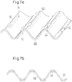
- FIG Figure 7a A view of a layer 10 according to the invention is shown in FIG Figure 7a shown in perspective.
- Figure 7b is a view of the situation according to Figure 7a in the direction of the fold.
- the associated structured packing 1 comprises the first layer 10 and a second layer 100, the second layer 100 preferably having a wave-like profile like the first layer 10.
- the first layer 10 and the second layer 100 are arranged in such a way that the channels of the first layer 10 intersect with the channels of the second layer 100.
- the first layer 10 is in touching contact with the second layer 100 via the crests of the wave troughs of the second layer 100 which lie opposite the wave crests of the first layer 10.
- the first and second vertices 33, 43, 133, 143 are arranged on each of the first and second layers 10, 100.
- first and second vertices 33, 43, 133, 143 which form points of contact, as in FIG Fig. 5 or Fig. 6 arranged.
- the points of contact are shown in these figures with a circle. At the places where there is no circle, there is no point of contact, but an indentation.
- the second layer 100 is in Fig. 7 not shown in the drawing for the sake of simplicity.
- the indentations 24, 44 of the first layer 10 have at least one point at a distance from the first and second peaks, not shown, of the wave troughs of the second layer 100, which are in the Fig. 7 would be arranged above.
- the indentations 44 which are located in the vicinity of the first edge delimitation 50, are preferably arranged in such a way that they are designed as depressions on a first side 11 of the layer 10.
- the indentations 24, which are arranged between the first edge delimitation 50 and the second edge delimitation 60, are designed as indentations on a second side 13 of the layer 10.
- the first side 11 of the layer 10 is arranged opposite the second side 13 and each forms a surface of the layer.
- the indentations can be arranged one below the other.
- the indentations can be arranged next to one another when the first and second layers are aligned vertically.
- indentations can also be arranged along an apex of the layer 10, 100, which indentations do not have to be formed, or do not have to be formed exclusively as dents.
- Such an indentation can comprise a cavity in which an insert element is contained at a distance from the apex of the adjacent layer having a profile. The profile is designed in such a way that it falls below the normal folding height at least in sections.
- the folding height is understood to mean the distance between a wave crest and an adjacent wave trough. If the wave crest has a finite curvature at its apex, the distance is defined as the normal distance between the two vertex rods lying parallel to one another. If the curvature is infinite, i.e.
- a plane is laid through the highest point which contains all the vertices on one side of the layer.
- a level is also laid through the deepest point of a wave trough, which contains all points of the Contains wave troughs and other wave troughs. The two planes should be parallel to each other. It follows that the fold height is the normal distance between the two levels.
- Indentations according to one of the preceding exemplary embodiments extend over part of the apex or the edge.
- the indentations can be produced from the blank for the layer, for example a packing sheet, by reshaping, that is to say pressing, embossing or deep drawing.
- the indentations are advantageously made on one side on the crests of the wave crests or the valleys of the folds.
- a blank can be produced endlessly.
- a blank can consist of strip material, for example be designed as a plate-shaped sheet metal. Sections of a certain length are then cut from the strip material. These sections are converted into a wave-like profile, for example by means of a bending process. Alternatively, strip material is used that already has a wave-like profile. The cut section with the wave-like profile then forms the layer. A forming process can be superimposed on this wave-like profile during the bending process, so that the indentations are produced during the bending process.
- a first layer 10 and a second layer 100 are in turn placed on top of each other by sweeping every second wave-like profile. Between all the layers there is at least one row of indentations in the vicinity of the upper and lower edge delimitations and / or in the vicinity of the lateral edge delimitations.
- the depth of the indentations is in the range from 10 to 30% of the layer height, so that gaps between the individual packing layers of precisely this range of values result.
- the gaps are at least 1.5 mm for aqueous systems. Narrower gaps can be disadvantageous since liquid, in particular water, can get stuck between two adjacent edges, can remain there and form a liquid bridge.
- Figure 8a shows a layer according to a known design with folds of different heights to reduce the contact points.
- the disadvantage of this design is that when there is a load on the top and bottom, the layer is compressed, the arrows 20, 21 indicating the direction of the force in which the layer is compressed.
- the folds comprise a first vertex 65 and a second vertex 85 as well as a corrugation trough 75 lying therebetween.
- the first and second vertices 65, 85 can be in contact with an adjacent layer (not shown).
- Between the first apex 65 and the valley floor 75 lie an intermediate wave valley 66 and an intermediate wave peak 67, which form a fold.
- the intermediate valley 66 has an intermediate valley floor 68 and the intermediate wave peak 67 has an intermediate apex 69.
- the normal distance 70 between the intermediate valley floor 68 and the intermediate apex 69 is smaller than the normal distance 71 between the apex 65 and the valley floor 75.
- the normal distance 70 is in the in Figure 8a
- the exemplary embodiment shown is approximately half as large as the normal distance 71.
- the intermediate wave valley 66 and the intermediate wave crest 67 thus form a half-height fold.
- the half-height fold serves as a crumple zone and can be deformed. Due to this deformation, on the one hand, a stable packing body cannot be built, and on the other hand, it is not possible to maintain a fixed layer height of the packing.
- the layer height corresponds to the previously defined normal distance 71.
- the surface of the indentations is available for the exchange of substances. This means that a gain in mass transfer area can be expected not only in comparison with the prior art, but also in comparison to conventional packings which have intersecting layers with a wave-shaped profile, the wave height of which is constant.
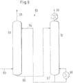
- Fig. 9 shows an absorption system 90.
- the absorption system 90 comprises two mass transfer devices, an absorber 91 and a desorber 92, which are designed in particular as columns.
- an absorber 91 In the absorption system, one or more components are separated from a gas flow in the absorber 91.
- a liquid solvent or absorbent is used for this purpose.
- the desorber 92 the solvent or absorbent is cleaned from the absorbed components.
- Both absorption and rectification are separation processes in order to separate one or more components from an existing feed stream 93. Rectification is used to separate liquid mixtures due to different boiling temperatures of the individual components, rectification being understood as a continuous distillation, which in particular comprises several separation stages.
- absorption on the other hand, one or more components are absorbed from a gas flow with the aid of a suitable solvent or absorbent 94 and are thus separated from the gas flow.
- the top product of the absorber 91 is thus a purified gas stream 95.
- the bottom product 96 of the absorber 91 is an absorbent or solvent loaded with the component or components.
- the cleaning of the absorbent or solvent takes place in the desorber 92.
- the loaded absorbent or solvent that is to say the bottom product 96 of the absorber, forms the feed stream of the desorber. This feed stream is according to Fig. 10 abandoned as a liquid in the desorber.
- the desorber 92 can contain one or more packs according to one of the preceding exemplary embodiments.
- the loaded solvent or absorbent flows in the direction of the sump 95 of the desorber.
- the absorbent or solvent is at least partially evaporated in the sump, for which purpose a sump evaporator 98 is provided.
- the absorbent or solvent evaporated in the bottom evaporator contains the components to be separated off and takes the components to be separated off from the feed stream of the loaded absorbent or flowing in the direction of the bottom while ascending in the column Solvent.
- a gaseous partial flow 99 which is enriched with the components to be separated off, thus arises in the desorber.
- These components to be separated off can be separated from the gaseous substream 99 either thermally, that is to say by condensation, or via other subsequent separation steps.
- expansion devices can be provided if the desorber is to be operated at a lower pressure than the absorber, or compression devices if the desorber has to be operated at a higher pressure than the absorber.
- the mass transfer between gas and liquid generally takes place in both directions due to a temperature gradient from the sump to the top.
- the higher-boiling fluid condenses out of the gaseous phase and is absorbed in the liquid and the low-boiling fluid evaporates from the liquid phase into the gaseous phase.
- the material transport only takes place in one direction, here gas is absorbed by the liquid.
- a prototype of a pack was produced which contains the indentations according to the invention in order to reduce the number of contact points.
- the distance between two vertices created by the indentation is 2.5 mm.
- the number of contact points for the prototype is reduced from 37,500m -3 to 18,000m -3 , thus an approximately 50% lower number of contact points compared to the prior art with the same total surface area of 205m 2 / m 3 .
- This prototype is made with a known pack without indentations, for example according to CH398503 compared with the same geometric area.
- the indentations reduce the number of contact points in the prototype.
- the gas flowing along the cross channels can partially be introduced as a branch flow through the indentations into an adjacent cross channel. Due to this changed gas flow, however, a rather reduced separation effect is to be expected in the prototype.
- the prototype mentioned above was first tested in an absorption column with an internal diameter of 300 mm. Isopropanol was absorbed from air with water. This is a predominantly gas-controlled system, similar to rectification. As expected, a smaller number of transfer units or NTUM (number of transfer units per meter) was measured for the prototype, which was measured in Fig. 10 is shown as a first series of measuring points 52, 53, 54. The greater the number of NTUMs, the more efficient the pack is with regard to mass transfer.
- the illustration shows an example of the NTUM for a selected F-factor of 1.5Pa 0.5 for a pack according to CH398503 and the pack according to the invention. The Liquid load L was varied.
- the F-factor is a measure of the mean gas velocity in the empty column multiplied by the square root of the density of the gas.
- the F-factor is proportional to the kinetic energy of the gas.
- the measuring points 55, 56, 57 for the previously known pack according to FIG CH398503 show a higher NTUM value than measuring points 52, 53, 54 for the pack according to the invention.
- Fig. 11 shows measuring points for this system with the prototype for liquid loads of approximately 10 to 80 m 3 / m 2 h, whereby the measuring points 58, 59, 63, 64, 72, 73, 74 for the prototype have a higher NTUM value than the measuring points 78, 79, 83, 84, 86, 87, 88 for the previously known pack. How Fig.
- the inventive packing of the prototype with a reduced number of contact points leads to at least as good a separation performance as the reference packing despite the changed gas flow. This means that the separation performance can actually be improved in certain systems by reducing the number of contact points and arranging the contact points appropriately.
- the pressure loss can also be reduced by using the packing according to the invention.
- the lower curve 101 of the Fig. 11 shows the NTUM for a standard structured packing according to CH398503 with increasing loading of the mass transfer apparatus with less volatile fluid at an F-factor of 1.5Pa 0.5 , the loading L in m 3 / m 2 h being plotted on the x-axis.
- the upper curve 102 the Fig. 11 shows in comparison the NTUM for a structured packing according to the invention. For all measured points under consideration with the same load L, the result is that NTUM is larger when using a pack with indentations than for a pack without indentations.
Description
Die Erfindung betrifft eine strukturierte Packung sowie einen Stoffaustauschapparat, welcher eine derartige strukturierte Packung enthält, beispielsweise eine Absorptionskolonne oder eine Desorptionskolonne.The invention relates to a structured packing and a mass transfer apparatus which contains such a structured packing, for example an absorption column or a desorption column.
Strukturierte Packungen sind in einer handelsüblichen Ausführungsform als gefaltete, hintereinander angeordnete Bleche ausgeführt, deren Struktur geneigte und sich immer wieder kreuzende Kanäle aufweist. Diese Kanäle beeinflussen die Strömungen von Gas- und Flüssigphase innerhalb der Packung positiv und begünstigen den Stofftransport zwischen den Phasen. Das heisst, in den Kanälen der Packung werden Gas- und Flüssigphase in Kontakt gebracht und somit der Stofftransport zwischen den Phasen begünstigt.In a commercially available embodiment, structured packings are designed as folded sheets of metal arranged one behind the other, the structure of which has inclined and repeatedly intersecting channels. These channels have a positive effect on the flow of gas and liquid phases within the packing and promote the transport of substances between the phases. This means that the gas and liquid phases are brought into contact in the channels of the packing, thus promoting the transport of substances between the phases.
Um die Trennleistung einer strukturierten Packung zu steigern, wird üblicherweise die Oberfläche der strukturierten Packung vergrössert, was zumeist durch eine höhere Anzahl an Lagen und/oder engere Kanalgeometrien erreicht wird. Diese Massnahmen führen allerdings zu einer Erhöhung des Druckabfalls in der strukturierten Packung. Daraus folgt aber, dass zur Verringerung des Druckabfalls weniger Packungsoberfläche vorgesehen werden muss, wodurch sich die Trennleistung verschlechtert, also die Effizienz der Packung. Zudem können offenere Kreuzungskanäle vorgesehen werden. Offenere Kreuzungskanäle bedeutet, dass der Neigungswinkel der Kanäle bezogen auf die Hauptströmungsrichtung geringer gewählt wird. Das bedeutet, dass je nach Anwendungsfall ein Optimum zwischen Druckabfall und bestmöglicher Trennleistung gefunden werden muss.In order to increase the separation performance of a structured packing, the surface of the structured packing is usually enlarged, which is mostly achieved by a higher number of layers and / or narrower channel geometries. However, these measures lead to an increase in the pressure drop in the structured packing. It follows from this, however, that less packing surface has to be provided in order to reduce the pressure drop, as a result of which the separation performance deteriorates, that is to say the efficiency of the packing. In addition, more open intersection channels can be provided. More open intersection channels means that the The angle of inclination of the channels is selected to be lower in relation to the main flow direction. This means that, depending on the application, an optimum must be found between pressure drop and the best possible separation performance.
Die sich kreuzenden Kanäle weisen jedoch viele Kontaktstellen auf, die sich in einigen Anwendungen positiv in anderen Anwendungen auch negativ auswirken können.However, the intersecting channels have many contact points, which in some applications can have a positive effect in other applications.
Stromabwärts der Kontaktstellen, gesehen in Richtung der strömenden Flüssigkeit können sich Totzonen ausbilden, in denen die Flüssigkeit in geringerem Mass am Stoffaustausch beteiligt ist, als die restliche Flüssigkeit, die sich auf der strukturierten Packung befindet. Dieses Phänomen ist bereits aus US 6'378'332 B1 bekannt, in welcher eine Packung für die kryogene Rektifikation beschrieben wird, die das Auftreten solcher Totzonen reduzieren soll. Die Lösung gemäss US 6'378'332 B1, liegt darin, die Anzahl der Kontaktstellen zwischen den Lagen durch abwechselnd hohe und weniger hohe Faltungen jeder Einzellage zu reduzieren.Downstream of the contact points, seen in the direction of the flowing liquid, dead zones can form in which the liquid participates in the mass transfer to a lesser extent than the remaining liquid located on the structured packing. This phenomenon is already known from US Pat. No. 6,378,332 B1, in which a pack for cryogenic rectification is described, which is intended to reduce the occurrence of such dead zones. The solution according to US Pat. No. 6,378,332 B1 is to reduce the number of contact points between the layers by alternately high and less high folds of each individual layer.
Aus der US 6'378'332 B1 ist somit ein Rektifikationsverfahren bekannt, in welchem eine strukturierte Packung verwendet wird, welche eine Kreuzkanalstruktur aufweist, das heisst aus gewellten oder gefalteten Blechen besteht, die kreuzweise übereinander gelegt sind. Benachbarte Bleche berühren sich längs der Wellenberge bzw. Kanten. Zwischen den gefalteten Blechen kann ein leichter flüchtiges Fluid, insbesondere eine Gasphase, im Gegenstrom zu einem schwerer flüchtigen Fluid, insbesondere eine Flüssigphase, strömen, wobei ein Stoffaustausch stattfinden kann. In der US 6'378'332 B1 wird ein Verfahren gezeigt, um die Anzahl der Kontaktpunkte zwischen zwei benachbarten Blechen zu reduzieren. Hierzu wird vorgesehen, die Höhe der Wellenberge oder Kanten derart zu variieren, dass nur noch ein Teil der Wellenberge oder Kanten jedes Blechs die maximale Höhe aufweist. Die Bleche berühren einander somit nur entlang der Wellenberge oder Kanten mit maximaler Höhe.From US Pat. No. 6,378,332 B1 a rectification process is known in which a structured packing is used which has a cross-channel structure, that is to say consists of corrugated or folded metal sheets which are placed crosswise on top of one another. Adjacent sheets touch each other along the wave crests or edges. A more volatile fluid, in particular a gas phase, can flow between the folded metal sheets in countercurrent to a less volatile fluid, in particular a liquid phase, whereby an exchange of substances can take place. US Pat. No. 6,378,332 B1 shows a method for reducing the number of contact points between two adjacent metal sheets. For this purpose, provision is made for the height of the wave crests or edges to be varied in such a way that only some of the wave crests or edges of each sheet metal have the maximum height. The sheets therefore only touch one another along the corrugation crests or edges with maximum height.
Ein Nachteil der gemäss US 6'378'332 B1 vorgeschlagenen Packung besteht in ihrer ungenügenden mechanischen Stabilität. Ausserdem wird das durch die Packung ausgefüllte Volumen wegen der zum Teil weniger hohen Faltungen nicht optimal mit geometrischer Austauschfläche ausgefüllt, das heisst diese konstruktive Ausgestaltung geht mit einem Verlust an Stoffaustauschfläche einher.A disadvantage of the packing proposed according to US Pat. No. 6,378,332 B1 is its inadequate mechanical stability. In addition, that will go through the volume filled up with the packing is not optimally filled with a geometric exchange surface because of the folds that are sometimes less high, that is to say this structural configuration is associated with a loss of mass exchange surface.
Aus der
In der
Aufgabe der Erfindung ist daher eine strukturierte Packung bereitzustellen, die bei gleicher oder geringerer Anzahl der Kontaktpunkte eine verbesserte Stabilität aufweist.The object of the invention is therefore to provide a structured packing which has improved stability with the same or a smaller number of contact points.
Eine weitere Aufgabe der Erfindung besteht darin, den Stoffaustausch insbesondere in einem flüssigseitig kontrollierten Absorber oder Desorber zu verbessern.Another object of the invention is to improve the mass transfer, in particular in an absorber or desorber that is controlled on the liquid side.
Die Lösung besteht in einem Absorber oder Desorber gemäß dem Patentanspruch 1. Dieser enthält eine erste Lage für eine strukturierte Packung. Die erste Lage für die strukturierte Packung weist ein erstes wellenartiges Profil auf, wobei durch das wellenartige Profil eine Mehrzahl offener Kanäle ausgebildet ist. Die Kanäle umfassen ein erstes Wellental, einen ersten Wellenberg und einen zweiten Wellenberg, wobei der erste Wellenberg und der zweite Wellenberg das erste Wellental begrenzen, wobei der erste und der zweite Wellenberg einen ersten gerundeten Scheitel und einen zweiten gerundeten Scheitel aufweisen. Auf dem ersten Scheitel des ersten Wellenbergs ist eine sich in Richtung des ersten Scheitels erstreckende Einbuchtung ausgebildet, wobei das erste Wellental einen gerundeten Talgrund aufweist, wobei der Normalabstand zumindest eines Punktes der Einbuchtung zum Talgrund des Wellentals kleiner ist als der Normalabstand des ersten Scheitels zum Talgrund des Wellentals. Auf dem zweiten Scheitel ist eine zweite Einbuchtung (44) angeordnet und auf dem Talgrund ist eine dritte Einbuchtung angeordnet, wobei die ersten, zweiten und dritten Einbuchtungen als linsenförmige Delle ausgebildet sind. Die Tiefe jeder Einbuchtung liegt im Bereich von 10 bis 30% der Lagenhöhe, so dass sich Spalten zwischen den einzelnen Packungslagen von eben diesem Wertebereich ergeben.The solution consists in an absorber or desorber according to
Des weiteren ist eine zweite Lage vorgesehen, wobei die zweite Lage ein zweites wellenartiges Profil aufweist, wobei die erste Lage und die zweite Lage derart angeordnet sind, dass sich die Kanäle der ersten Lage mit den Kanälen der zweiten Lage kreuzen. Die erste Lage steht mit der zweiten Lage in berührendem Kontakt, wobei der berührende Kontakt im Bereich jeder der Einbuchtung unterbrochen ist.Furthermore, a second layer is provided, the second layer having a second wave-like profile, the first layer and the second layer being arranged in such a way that the channels of the first layer intersect with the channels of the second layer. The first layer is in touching contact with the second layer, the touching contact being interrupted in the area of each of the indentations.
Somit ergibt sich durch die Einbuchtungen die Schaffung einer zusätzlichen Möglichkeit für die Führung der Flüssigkeitsströmung, sowie einer Anordnung der Kontaktstellen, die eine maximale Flüssigkeitsbenetzung der Packungsoberfläche ermöglicht.The indentations thus create an additional possibility for guiding the liquid flow, as well as an arrangement the contact points, which enables maximum liquid wetting of the packing surface.
Auf dem zweiten Scheitel ist eine zweite Einbuchtung und auf dem ersten Talgrund ist eine dritte Einbuchtung angeordnet. Selbstverständlich können auf der Lage eine Mehrzahl von ersten, zweiten oder dritten Einbuchtungen vorgesehen sein.A second indentation is arranged on the second apex and a third indentation is arranged on the first valley floor. Of course, a plurality of first, second or third indentations can be provided on the layer.
Jede Lage kann eine erste Randbegrenzung, sowie eine zweite Randbegrenzung umfassen, wobei die erste Randbegrenzung im wesentlichen parallel zur zweiten Randbegrenzung angeordnet ist. Insbesondere kann eine Mehrzahl von Einbuchtungen zwischen der ersten Randbegrenzung und der zweiten Randbegrenzung angeordnet sein.Each layer can comprise a first edge delimitation and a second edge delimitation, the first edge delimitation being arranged essentially parallel to the second edge delimitation. In particular, a plurality of indentations can be arranged between the first edge delimitation and the second edge delimitation.
Zur Verbesserung der Stabilität bei gleicher oder geringerer Anzahl der Kontaktpunkte weist die Lage ein wellenartiges Profil auf, wobei die Wellenhöhe im wesentlichen konstant ist.To improve the stability with the same or a smaller number of contact points, the layer has a wave-like profile, the wave height being essentially constant.
Nach einem bevorzugten Ausführungsbeispiel ist zumindest ein Teil der Scheitel als Kante und/oder zumindest ein Teil der Wellentäler v-förmig ausgebildet.According to a preferred embodiment, at least some of the vertices are formed as an edge and / or at least some of the wave troughs are V-shaped.
Eine strukturierte Packung umfasst somit eine erste Lage nach einem der vorhergehenden Ausführungsbeispiele und eine zweite Lage, wobei die zweite Lage ein wellenartiges Profil wie die erste Lage aufweist, wobei die erste Lage und die zweite Lage derart angeordnet sind, dass sich die Kanäle der ersten Lage mit den Kanälen der zweiten Lage kreuzen. Die erste Lage steht mit der zweiten Lage in berührendem Kontakt, bevorzugt indem sich die Scheitel der Wellenberge der ersten Lage und die Scheitel der Wellentäler der zweiten Lage berühren.A structured packing thus comprises a first layer according to one of the preceding exemplary embodiments and a second layer, the second layer having a wave-like profile like the first layer, the first layer and the second layer being arranged such that the channels of the first layer are arranged cross with the channels of the second layer. The first layer is in touching contact with the second layer, preferably in that the crests of the wave crests of the first layer and the crests of the wave troughs of the second layer touch one another.
Die Einbuchtungen können auf jeder der ersten und zweiten Lagen angeordnet sein. Durch die Einbuchtungen ist der Kontakt der ersten Lage mit der zweiten Lage unterbrochen.The indentations can be arranged on each of the first and second layers. The contact of the first layer with the second layer is interrupted by the indentations.
Eine erfindungsgemässe Packung besteht aus strukturierten Lagen, deren Faltungen alle gleichmässig hoch sind. Hierdurch wird eine hohe Stabilität der Packung gewährleistet, die besonders in Kolonnen mit grossem Durchmesser von besonderer Bedeutung ist. Die Reduktion der Anzahl der Kreuzungspunkte der einzelnen Lagen wird erfindungsgemäss durch das Einbringen von Einbuchtungen realisiert. Diese Einbuchtungen sind als linsenförmige Dellen ausgebildet, die zum Beispiel durch plastische Verformung des Scheitels der Lage anbringbar sind. Die Einbuchtungen werden an bestimmen Stellen auf die gefalteten Packungslagen aufgebracht und somit sind die Packungslagen in einem definierten Abstand und an definierten Stellen voneinander trennbar.A pack according to the invention consists of structured layers, the folds of which are all of the same height. This ensures a high stability of the packing, which is particularly important in columns with a large diameter. According to the invention, the number of intersection points of the individual layers is reduced by making indentations. These indentations are designed as lens-shaped dents which can be made, for example, by plastic deformation of the apex of the layer. The indentations are applied to the folded packing layers at specific points and thus the packing layers can be separated from one another at a defined distance and at defined points.
Als Alternative könnten die Einbuchtungen in die Packungslage durch Vorsehen eines Hohlraums, in welchem ein Einsatzelement anbringbar ist ausgestaltet sein.As an alternative, the indentations in the packing layer could be designed by providing a cavity in which an insert element can be attached.
Des weiteren kann sich zumindest ein Teil der Einbuchtungen über eine Länge erstrecken, die bis zu 75% der Länge des Scheitels beträgt. Die Einbuchtung ist vorteilhafterweise innerhalb zumindest einer der ersten oder zweiten Randbegrenzungen angeordnet, sodass der Randbereich für eine erhöhte Formstabilität der Packung ausgebildet ist.Furthermore, at least some of the indentations can extend over a length which is up to 75% of the length of the apex. The indentation is advantageously arranged within at least one of the first or second edge delimitations, so that the edge region is designed for increased dimensional stability of the pack.
Jede der Einbuchtungen kann durch eine Erhebung unterbrochen sein. Die Einbuchtungen der ersten Lage können mit den Einbuchtungen der zweiten Lage zumindest teilweise überlappend angeordnet sein.Each of the indentations can be interrupted by an elevation. The indentations of the first layer can be arranged at least partially overlapping with the indentations of the second layer.
Die Einbuchtung kann eine Zwischenerhebung umfassen, insbesondere wenn sich die Einbuchtung um bis zu 75% der Länge des Scheitels erstreckt. Die Zwischenerhebung kann auf dem Scheitel der benachbarten Lage aufliegen oder in einem Abstand zu derselben angeordnet sein.The indentation can comprise an intermediate elevation, in particular if the indentation extends by up to 75% of the length of the apex. The intermediate elevation can rest on the apex of the adjacent layer or be arranged at a distance from the same.
Jede der Lagen kann eine Öffnung enthalten. Eine derartige Öffnung kann den Durchtritt von Gas und/oder Flüssigkeit auf eine benachbarte Lage erleichtern. Derartige Öffnungen können im Wandbereich der Faltung, auf den Scheiteln der Wellenberge oder Wellentäler oder auch im Bereich der Einbuchtungen angeordnet sein.Each of the layers can contain an opening. Such an opening can facilitate the passage of gas and / or liquid to an adjacent layer. Such openings can be in the wall area of the fold on the The crests of the wave crests or troughs or also be arranged in the area of the indentations.
Nach Möglichkeit erfolgt die Herstellung der Einbuchtung gemeinsam mit der Herstellung der Lage durch ein Umformverfahren. Somit kann die Herstellung der Lage mit einer minimalen Anzahl an Prozessschritten erfolgen. Hierzu können die Einbuchtungen an definierten Stellen, z.B. an der Ober- und Unterkante der Packungslage, durch Eindrücken, Einprägen oder Tiefziehen aus dem Blech herausgearbeitet werden. Beim Übereinanderlegen der einzelnen Lagen berühren sich die Kanäle jeweils im Bereich der Einbuchtungen nicht. In zumindest je zwei der Randbereiche entweder an der Ober- und Unterkante der Lage oder an den Seitenkanten der Lage befinden sich keine Einbuchtungen, sodass genügend Kontaktstellen vorhanden sind, um benachbarte Lagen in dem durch die Wellenhöhe definierten Abstand voneinander zu halten. Durch das Vorsehen einer Mehrzahl von Einbuchtungen innerhalb jedes der Randbereiche wird eine deutliche Reduktion der Kontaktstellen bewirkt sowie eine Maximierung der benetzten Packungsoberfläche bei gleichzeitiger Stabilität der einzelnen Lagen und damit auch des Packungskörpers, der aus einer Mehrzahl von Lagen besteht.If possible, the indentation is produced together with the production of the layer by means of a forming process. The production of the layer can thus take place with a minimal number of process steps. For this purpose, the indentations can be worked out of the sheet metal at defined points, e.g. on the upper and lower edge of the pack layer, by pressing, embossing or deep drawing. When the individual layers are placed on top of one another, the channels do not touch each other in the area of the indentations. There are no indentations in at least two of the edge areas either on the upper and lower edge of the layer or on the side edges of the layer, so that there are enough contact points to keep adjacent layers at the distance defined by the wave height. By providing a plurality of indentations within each of the edge areas, a significant reduction in the contact points is achieved and the wetted packing surface is maximized with simultaneous stability of the individual layers and thus also of the packing body, which consists of a plurality of layers.
Der Abstand benachbarter Packungslagen bleibt konstant, auch wenn die Einbuchtungen sich auf Scheiteln befinden, welche die offenen Kanäle begrenzen. Unter Scheitel kann sowohl ein Wellenberg als auch eine Kante verstanden werden, also eine Spitze, die durch zwei benachbarte Seitenflächen eines Kanals ausgebildet ist.The distance between adjacent packing layers remains constant, even if the indentations are located on vertices which delimit the open channels. A crest can be understood to mean both a wave crest and an edge, that is to say a tip that is formed by two adjacent side surfaces of a channel.
Für die Reinigung eines leichter flüchtigen Fluids, insbesondere eines Gases, erfolgt der Stoffaustausch in mehreren sequentiell ablaufenden Teilschritten. Die im Gas enthaltenen Komponenten, die abgetrennt werden müssen, werden durch Konvektion und Diffusion an die Grenzfläche zur Flüssigkeit transportiert. Anschliessend müssen die Komponenten die Grenzfläche passieren und in der Flüssigkeit aufgenommen werden. Damit der Stoffaustausch verbessert werden kann, ist es vorteilhaft, eine möglichst grosse Stoffaustauschfläche für die Flüssigkeit vorzusehen.For the purification of a more volatile fluid, in particular a gas, the mass transfer takes place in several sequential partial steps. The components contained in the gas that have to be separated are transported to the interface with the liquid by convection and diffusion. The components then have to pass the interface and be absorbed in the liquid. So that the mass transfer can be improved, it is advantageous to provide the largest possible mass transfer surface for the liquid.
Eine weitere Aufgabe der Erfindung besteht darin, die Anordnung der Kontaktpunkte derart zu wählen, dass es durch die Kontaktpunkte zu einer minimalen Veränderung des Stoffaustauschs kommt.Another object of the invention is to select the arrangement of the contact points in such a way that the contact points result in a minimal change in the exchange of substances.
Insbesondere sind in der Vorrichtung nach einem der vorhergehenden Ausführungsbeispiele die Kontaktpunkte vermehrt im Randbereich der ersten Lage angeordnet. Im Gegensatz zum Stand der Technik, nach welchem eine immer noch gleichmässige Verteilung der Kontaktpunkte angestrebt wird, die Anzahl der Kontaktpunkte aber verringert wird, kann in der Erfindung auf diese gleichmässige Verteilung der Kontaktpunkte über der Oberfläche der Packung verzichtet werden. Werden somit die wenigen Kontaktstellen enger zusammen gelegt, bewirkt die Strömungsverengung eine Rückströmung hinter den Kontaktstellen, wodurch die unbenetzte Fläche hinter der Kontaktstelle reduziert wird. Demzufolge ergeben sich wenige Kontaktstellen mit weniger unbenetzter Fläche und in der Summe ein minimales Verhältnis aus unbenetzter zu gesamter Packungsoberfläche.In particular, in the device according to one of the preceding exemplary embodiments, the contact points are increasingly arranged in the edge region of the first layer. In contrast to the prior art, according to which a uniform distribution of the contact points is still sought, but the number of contact points is reduced, this uniform distribution of the contact points over the surface of the pack can be dispensed with in the invention. If the few contact points are thus placed closer together, the flow constriction causes a backflow behind the contact points, whereby the unwetted area behind the contact point is reduced. As a result, there are fewer contact points with less unwetted area and, in total, a minimal ratio of unwetted to total pack surface.
Nach einem vorteilhaften Ausführungsbeispiel der Vorrichtung befinden sich eine Mehrzahl von Einbuchtungen auf jeder der Lagen. In diesem Fall sind alle Lagen gleich aufgebaut, was den Herstellungsaufwand reduziert. Die Lagen können in dieser Form kontinuierlich hergestellt werden, indem ein Band kontinuierlich gefaltet wird, währenddessen auch die Einbuchtungen erzeugt werden. Das gefaltete und mit Einbuchtungen versehene Band wird auf die gewünschten Abmessungen zugeschnitten. Die zugeschnittenen Bandteile ergeben die Lagen, wobei jede zweite Lage gekehrt wird, sodass eine kreuzweise Anordnung von Lagen entsteht, wenn sie benachbart zueinander aufeinander gelegt werden.According to an advantageous embodiment of the device, there are a plurality of indentations on each of the layers. In this case, all layers have the same structure, which reduces manufacturing costs. The layers can be produced continuously in this form by continuously folding a band, during which the indentations are also produced. The folded and indented tape is cut to the desired dimensions. The cut tape parts result in the layers, with every other layer being turned so that a cross-wise arrangement of layers is created when they are placed one on top of the other next to one another.
Ein Stoffaustauschapparat, insbesondere eine Kolonne kann eine strukturierte Packung nach einem der vorhergehenden Ansprüche umfassen.A mass transfer apparatus, in particular a column, can comprise a structured packing according to one of the preceding claims.
Ein Verfahren zur Reinigung von Fluiden in einem Stoffaustauschapparat, welcher eine strukturierte Packung enthält, umfasst die Schritte: Zuführen eines schwerer flüchtigen Fluids zu dem Stoffaustauschapparat, Verteilen des zugeführten schwerer flüchtigen Fluids über der Oberfläche der Packung, Zuführen eines leichter flüchtigen Fluids in den Stoffaustauschapparat in einen Fluideintrittsbereich, Verteilen des leichter flüchtigen Fluids im Gaseintrittsbereich über die Oberfläche der Packung, wobei das leichter flüchtige Fluid im Gegenstrom zur Flüssigkeit strömt, Sammeln des leichter flüchtigen Fluids, welches die Packung verlässt in einem Fluidaustrittsbereich, wobei die strukturierte Packung eine erste Lage und eine zweite Lage enthält, wobei die erste Lage und die zweite Lage ein wellenartiges Profil mit konstanter Wellenhöhe aufweisen, wobei durch das wellenartige Profil offene Kanäle ausgebildet sind, wobei sich die Kanäle der ersten Lage mit den Kanälen der zweiten Lage kreuzen, wobei das leichter flüchtige Fluid durch die Kanäle vom Fluideintrittsbereich in Richtung des Fluidaustrittsbereichs strömt, wobei das schwerer flüchtige Fluid das durch die Kanäle strömende leichter flüchtige Fluid umgibt und entlang der Kanalwände strömt. Die erste Lage steht mit der zweiten Lage über die Scheitel der Wellenberge in berührendem Kontakt, sodass ein Stoffaustausch zwischen dem leichter flüchtigen Fluid und dem schwerer flüchtigen Fluid über die durch die Kanäle gebildete Stoffaustauschfläche erfolgt.A method for cleaning fluids in a mass transfer apparatus which contains a structured packing comprises the steps: supplying a less volatile fluid to the mass transfer apparatus, distributing the supplied less volatile fluid over the surface of the packing, supplying a more volatile fluid into the mass transfer apparatus a fluid inlet area, distributing the more volatile fluid in the gas inlet area over the surface of the packing, the more volatile fluid flowing in countercurrent to the liquid, collecting the more volatile fluid that leaves the packing in a fluid outlet area, the structured packing having a first layer and a contains second layer, wherein the first layer and the second layer have a wave-like profile with constant wave height, wherein open channels are formed by the wave-like profile, the channels of the first layer intersect with the channels of the second layer, the more volatile fluid flows through the channels from the fluid inlet area in the direction of the fluid outlet area, the less volatile fluid surrounding the more volatile fluid flowing through the channels and flowing along the channel walls. The first layer is in touching contact with the second layer via the apex of the wave crests, so that a mass transfer between the more volatile fluid and the less volatile fluid takes place via the mass transfer surface formed by the channels.
Durch Verwendung von Einbuchtungen sowie einer Anordnung der Kontaktstellen wird eine maximale Flüssigkeitsbenetzung der Packungsoberfläche in Stoffaustauschapparaten ermöglicht.The use of indentations and an arrangement of the contact points enables maximum liquid wetting of the packing surface in mass transfer devices.
Vorzugsweise besteht die Packung aus strukturierten Lagen, deren Faltungen alle gleichmässig hoch sind. Hierdurch wird eine hohe Stabilität der Packung erzeugt, die besonders in Kolonnen mit grossem Durchmesser von besonderer Bedeutung ist. Die Anzahl der Kreuzungspunkte zwischen den einzelnen Lagen wird erfindungsgemäss durch das Einbringen von Einbuchtungen an den Scheiteln von Wellenbergen zumindest je einer von zwei benachbarten Lagen reduziert.The pack preferably consists of structured layers, the folds of which are all of the same height. This creates a high stability of the packing, which is particularly important in columns with a large diameter. According to the invention, the number of intersection points between the individual layers is reduced by making indentations at the apexes of wave crests at least one of two adjacent layers.
Nachfolgend wird die Erfindung anhand der Zeichnungen erläutert. Es zeigen:
- Fig. 1
- eine Ansicht einer Vorrichtung umfassend eine Mehrzahl von Packungslagen,
- Fig. 2a
- eine Schnittdarstellung durch zwei benachbarte Packungslagen
- Fig. 2b
- eine Ansicht von zwei benachbarten Packungslagen mit gewelltem Profil gemäss der Erfindung,
- Fig. 3
- eine Darstellung einer konventionellen Packungslage unter Angabe des Strömungswegs des schwererflüchtigen Fluids,
- Fig. 4
- eine Darstellung der Knotenpunkte nach der Lösung gemäss des Standes der Technik,
- Fig. 5
- eine Darstellung der Knotenpunkte gemäss eines ersten Ausführungsbeispiels der Erfindung,
- Fig. 6
- eine Darstellung der Knotenpunkte gemäss eines weiteren Ausführungsbeispiels der Erfindung,
- Fig. 7a
- eine Darstellung einer Variante der Anordnung der erfindungsgemässen Einbuchtungen auf einer Lage in der Perspektive,
- Fig. 7b
- eine Ansicht der Lage gemäss
Fig. 7a in Richtung der Faltung, - Fig. 8a
- eine Veranschaulichung der Verformung der Packung nach dem Stand der Technik unter Querbelastung,
- Fig. 8b
- eine Veranschaulichung der Verformung der erfindungsgemässen Packung unter Querbelastung,
- Fig. 9
- eine Darstellung einer Absorptionsanlage als Anwendungsbeispiel für die Erfindung.
- Fig. 10
- Messwerte für den NTUM Wert für ein gasseitig kontrolliertes Absorptionssystem oder Desorptionssystem
- Fig. 11
- Messwerte für den NTUM Wert für ein flüssigseitig kontrolliertes Absorptionssystem oder Desorptionssystem
- Fig. 1
- a view of a device comprising a plurality of packing layers,
- Fig. 2a
- a sectional view through two adjacent packing layers
- Figure 2b
- a view of two adjacent packing layers with a corrugated profile according to the invention,
- Fig. 3
- a representation of a conventional packing layer indicating the flow path of the less volatile fluid,
- Fig. 4
- a representation of the nodes after the solution according to the state of the art,
- Fig. 5
- a representation of the nodes according to a first embodiment of the invention,
- Fig. 6
- a representation of the nodes according to a further embodiment of the invention,
- Figure 7a
- a representation of a variant of the arrangement of the indentations according to the invention on a layer in perspective,
- Figure 7b
- a view of the situation according to
Figure 7a in the direction of the fold, - Figure 8a
- an illustration of the deformation of the pack according to the prior art under transverse loading,
- Figure 8b
- an illustration of the deformation of the packing according to the invention under transverse loading,
- Fig. 9
- a representation of an absorption system as an application example for the invention.
- Fig. 10
- Measured values for the NTUM value for a gas-controlled absorption system or desorption system
- Fig. 11
- Measured values for the NTUM value for a liquid-side controlled absorption system or desorption system
Die strukturierte Packung 7 besteht aus einer Mehrzahl von Lagen, die zueinander in einer sich regelmässig wiederholenden geometrischen Beziehung stehen. Als Beispiel für diese geometrische Beziehung kann der Abstand benachbarter Lagen gewählt werden. Gemäss der geometrischen Beziehung können die Abstände benachbarter Lagen voneinander periodisch den selben Wert annehmen, sodass aus der Summe der Lagen eine Struktur entsteht, die durch gleiche oder zumindest periodisch gleiche Abstände gekennzeichnet ist. Die Periodizität findet sich in der gesamten strukturierten Packung, wodurch die Packung eine regelmässige Struktur erhält. Insbesondere kann die Struktur als wellenartiges Profil ausgebildet sein.The structured packing 7 consists of a plurality of layers which are in a regularly repeating geometric relationship to one another. The distance between adjacent layers can be chosen as an example of this geometric relationship. According to the geometric relationship, the distances between adjacent layers can periodically assume the same value, so that the sum of the layers creates a structure that is characterized by the same or at least periodically equal distances. The periodicity is found in the entire structured packing, which gives the packing a regular structure. In particular, the structure can be designed as a wave-like profile.
Im Unterschied dazu bestehen Schüttfüllkörperpackungen aus Schüttfüllkörpern, das heisst aus Elementen von gleichem geometrischen Aufbau, wobei aber jeder Schüttfüllkörper zu benachbarten Schüttfüllkörpern beliebige Abstände aufweisen kann, somit eine Periodizität dieser Abstände nicht erkennbar ist. Die Schüttfüllkörper werden als Schüttung in die Kolonne eingebracht. Sie bilden ein Haufwerk auf einem Kolonnenboden aus. Das Haufwerk ist gekennzeichnet durch die zufällige Anordnung der einzelnen Schüttfüllkörper.In contrast to this, bulk fill packs consist of bulk fillers, that is to say of elements of the same geometric structure, but each bulk filler can have any spacing from adjacent bulk fillers, so that a periodicity of these spacings is not recognizable. The random packings are introduced into the column as a bed. They form a pile on a column bottom. The pile is characterized by the random arrangement of the individual random packing.
Die Lagen gemäss
Die erste Lage 10 und die zweite Lage 100 in der
Die erste Lage 10 der strukturierten Packung 7 weist ein wellenartiges Profil auf, wobei durch das wellenartige Profil eine Mehrzahl offener Kanäle 12, 14, 16 ausgebildet ist. Die Kanäle umfassen ein erstes Wellental 22, einen ersten Wellenberg 32 und einen zweiten Wellenberg 42. Der erste Wellenberg 32 und der zweite Wellenberg 42 begrenzen das erste Wellental 22. Der erste Wellenberg 32 und der zweite Wellenberg 42 weisen einen ersten Scheitel 33 und einen zweiten Scheitel 43 auf. Auf dem zweiten Scheitel 43 des zweiten Wellenbergs 42 ist ein sich in Richtung des zweiten Scheitels 43 erstreckende Einbuchtung 44 ausgebildet. Das erste Wellental 22 weist einen Talgrund 23 auf. Das erste Wellental 22 weist einen Talgrund 23 auf, wobei der Normalabstand 27 zumindest eines Punktes der Einbuchtung 34 zum Talgrund 23 des Wellentals 22 kleiner ist als der Normalabstand des ersten Scheitels 33 zum Talgrund 23 des Wellentals 22.The
Der Normalabstand zwischen dem ersten Scheitel 33 des ersten Wellenbergs 32 und dem Talgrund 23 des ersten Wellentals 22 wird als Wellenhöhe 28 bezeichnet. Die Wellenhöhe 28 ist demnach grösser als der Normalabstand 27. In einer Lage gemäss dieser Erfindung ist die Wellenhöhe 28 insbesondere im wesentlichen konstant, das heisst, sie liegt im Bereich der üblichen Toleranzen, die im Bereich von 0.5 mm liegen.The normal distance between the
Auch auf dem ersten Scheitel 33 kann eine erste Einbuchtung 34 angeordnet sein. Wahlweise kann auch auf dem ersten Talgrund 23 eine zweite Einbuchtung 24 angeordnet sein.A
Die zweite Lage 100 der strukturierten Packung 7 weist ein wellenartiges Profil auf, wobei durch das wellenartige Profil eine Mehrzahl offener Kanäle 112, 114, 116 ausgebildet ist. Die Kanäle umfassen ein erstes Wellental 122, einen ersten Wellenberg 132 und einen zweiten Wellenberg 142. Der erste Wellenberg 132 und der zweite Wellenberg 142 begrenzen das erste Wellental 122. Der erste Wellenberg 132 und der zweite Wellenberg 142 weisen einen ersten Scheitel 133 und einen zweiten Scheitel 143 auf. Auf dem ersten Scheitel 133 des ersten Wellenbergs 132 ist ein sich in Richtung des ersten Scheitels 133 erstreckende Einbuchtung 134 ausgebildet. Auf dem zweiten Scheitel 143 des zweiten Wellenbergs 142 ist eine sich in Richtung des zweiten Scheitels 143 erstreckende Einbuchtung 144 ausgebildet. Das erste Wellental 122 weist einen Talgrund 123 auf. Die Einbuchtung 134 und die Einbuchtung 144 weist einen kleineren Normalabstand vom Talgrund 123 des Wellentals 122 hat als der zweite Scheitel 143 des zweiten Wellenbergs 142 vom Talgrund 123 des Wellentals 122. Zumindest ein Teil der Scheitel kann als Kante ausgebildet sein. Zumindest ein Teil der Wellentäler kann v-förmig ausgebildet sein. Der Normalabstand zwischen Talgrund und Scheitel ist gemäss
Aus
Werden dagegen die wenigen Kontaktstellen enger zusammen gelegt, bewirkt die Strömungsverengung eine Rückströmung hinter den Kontaktstellen, wodurch wiederum die unbenetzte Fläche hinter der Kontaktstelle reduziert wird. Demzufolge ergeben sich wenige Kontaktstellen mit weniger unbenetzter Fläche und in der Summe ein minimales Verhältnis aus unbenetzter zu gesamter Oberfläche der Lage.If, on the other hand, the few contact points are placed closer together, the flow constriction causes a backflow behind the contact points, which in turn reduces the unwetted area behind the contact point. As a result, there are fewer contact points with less non-wetted surface and, in total, a minimal ratio of non-wetted to total surface of the layer.
Die Lage 10 umfasst eine erste Randbegrenzung 50, sowie eine zweite Randbegrenzung 60, wobei die erste Randbegrenzung 50 im wesentlichen parallel zur zweiten Randbegrenzung 60 angeordnet ist. Bei vertikaler Ausrichtung der Lage spannt die Randbegrenzung 50 eine obere Grenzfläche auf und die zweite Randbegrenzung 60 eine untere Grenzfläche auf. Des weiteren umfasst die Lage 10 eine erste Randbegrenzung 51 und eine zweite Randbegrenzung 61. Die erste Randbegrenzung 51 und die zweite Randbegrenzung 61 verlaufen bei vertikaler Ausrichtung der Lage in einer Packung benachbart der Innenwand des Stoffaustauschapparats, insbesondere der Kolonne. An zumindest eine der oberen Grenzfläche oder der unteren Grenzflächen kann ein Spalt anschliessen, an welchen zumindest eine weitere Packung angrenzt.The
Die Kontaktstellen 48 sind in der Nähe der ersten und/oder zweiten Randbegrenzung 50, 51, 60, 61 angeordnet. An diesen Kontaktstellen berühren sich die benachbarten Lagen. Zwischen diesen Kontaktstellen nahe der Randbegrenzungen werden durch Anbringen von Einbuchtungen weitere Kontaktstellen zumindest teilweise vermieden. Eine Mehrzahl von Einbuchtungen, welche den gleichen Aufbau wie eine der ersten, zweiten oder dritten Einbuchtungen 24, 34, 44 gemäss
Selbstverständlich können sich Einbuchtungen auch in der Nähe zumindest je einer der ersten und zweiten Randbegrenzungen befinden.Of course, indentations can also be located in the vicinity of at least one of the first and second edge delimitations.
In
Eine Ansicht einer Lage 10 gemäss der Erfindung ist in
Die zweite Lage 100 ist in
Insbesondere können die Einbuchtungen bei vertikaler Ausrichtung der ersten und zweiten Lagen 10, 100 untereinander angeordnet ein. Alternativ dazu oder in Kombination können die Einbuchtungen bei vertikaler Ausrichtung der ersten und zweiten Lagen nebeneinander angeordnet sein.In particular, when the first and
Entlang eines Scheitels der Lage 10, 100 können auch andere Einbuchtungen angeordnet sein, die nicht oder nicht ausschliesslich als Delle ausgebildet sein müssen. Eine derartige Einbuchtung kann einen Hohlraum umfassen, in welchem ein Einsatzelement mit einem Abstand zum Scheitel der benachbarten Lage aufweisenden Profil enthalten ist. Das Profil ist derart ausgestaltet, dass es zumindest abschnittsweise die normale Faltungshöhe unterschreitet. Unter Faltungshöhe wird der Abstand zwischen einem Wellenberg und einem benachbarten Wellental verstanden. Wenn der Wellenberg an seinem Scheitel eine endliche Krümmung aufweist, ist der Abstand als der Normalabstand der beiden, parallel zueinander liegenden Scheitelpunktstangenten definiert. Wenn die Krümmung unendlich ist, das heisst der Scheitel spitz ist und somit der höchste Punkt keine eindeutig bestimmte Tangente aufweist, wird durch den höchsten Punkt eine Ebene gelegt, die alle Scheitelpunkte einer Seite der Lage enthält. Durch den tiefsten Punkt eines Wellentals wird ebenfalls eine Ebene gelegt, die alle Punkte des Wellentals sowie weiterer Wellentäler enthält. Die beiden Ebenen sollten zueinander parallel liegen. Daraus folgt, dass die Faltungshöhe der Normalabstand zwischen den beiden Ebenen ist.Other indentations can also be arranged along an apex of the
Einbuchtungen gemäss eines der vorhergehenden Ausführungsbeispiele erstrecken sich über einen Teil des Scheitels oder der Kante. Die Einbuchtungen können durch Umformen, also Eindrücken, Prägen oder Tiefziehen aus dem Rohling für die Lage, beispielsweise einem Packungsblech hergestellt werden. Mit Vorteil werden die Einbuchtungen einseitig auf den Scheiteln der Wellenberge oder der Täler der Faltungen angebracht.Indentations according to one of the preceding exemplary embodiments extend over part of the apex or the edge. The indentations can be produced from the blank for the layer, for example a packing sheet, by reshaping, that is to say pressing, embossing or deep drawing. The indentations are advantageously made on one side on the crests of the wave crests or the valleys of the folds.
Der Vorteil dieser Anordnung besteht darin, dass ein Rohling endlos lang hergestellt werden kann. Ein derartiger Rohling kann aus Bandmaterial bestehen, beispielsweise als plattenförmiges Blech ausgebildet sein. Aus dem Bandmaterial werden anschliessend Abschnitte bestimmter Länge zugeschnitten. Diese Abschnitte werden beispielsweise durch ein Biegeverfahren in ein wellenartiges Profil umgewandelt. Alternativ dazu kommt Bandmaterial zum Einsatz, welches bereits ein wellenartiges Profil aufweist. Der zugeschnittene Abschnitt mit dem wellenartigen Profil bildet dann die Lage aus. Diesem wellenartigen Profil kann während des Biegevorgangs ein Umformvorgang überlagert werden, sodass während des Biegevorgangs die Einbuchtungen hergestellt werden. Eine erste Lage 10 und eine zweite Lage 100 werden wiederum durch Kehren jedes zweiten wellenartigen Profils passend übereinander gelegt. Zwischen allen Lagen befindet sich zumindest eine Reihe Einbuchtungen in der Nähe der oberen und unteren Randbegrenzung und/oder in der Nähe der seitlichen Randbegrenzungen.The advantage of this arrangement is that a blank can be produced endlessly. Such a blank can consist of strip material, for example be designed as a plate-shaped sheet metal. Sections of a certain length are then cut from the strip material. These sections are converted into a wave-like profile, for example by means of a bending process. Alternatively, strip material is used that already has a wave-like profile. The cut section with the wave-like profile then forms the layer. A forming process can be superimposed on this wave-like profile during the bending process, so that the indentations are produced during the bending process. A
Die Tiefe der Einbuchtungen liegt im Bereich von 10 bis 30% der Lagenhöhe, sodass sich Spalten zwischen den einzelnen Packungslagen von eben diesem Wertebereich ergeben. Die Spalten betragen minimal 1.5 mm für wässrige Systeme. Schmälere Spalten können nachteilig sein, da sich Flüssigkeit, insbesondere Wasser zwischen zwei benachbarten Kanten festsetzen kann, dort verbleiben kann und eine Flüssigkeitsbrücke ausbilden kann.The depth of the indentations is in the range from 10 to 30% of the layer height, so that gaps between the individual packing layers of precisely this range of values result. The gaps are at least 1.5 mm for aqueous systems. Narrower gaps can be disadvantageous since liquid, in particular water, can get stuck between two adjacent edges, can remain there and form a liquid bridge.
In
Durch eine erfindungsgemässe Bauform kann dieses Problem umgangen werden. Wie
Zudem steht die Oberfläche der Einbuchtungen für den Stoffaustausch zur Verfügung. Das bedeutet, dass nicht nur im Vergleich mit dem Stand der Technik ein Gewinn an Stoffaustauschfläche zu erwarten ist, sondern auch im Vergleich zu herkömmlichen Packungen, welche sich kreuzende Lagen mit wellenförmigem Profil aufweisen, deren Wellenhöhe konstant ist.In addition, the surface of the indentations is available for the exchange of substances. This means that a gain in mass transfer area can be expected not only in comparison with the prior art, but also in comparison to conventional packings which have intersecting layers with a wave-shaped profile, the wave height of which is constant.
Sowohl Absorption als auch Rektifikation sind Trennverfahren, um aus einem vorliegenden Einsatzstrom 93 eine oder mehr Komponenten heraus zu trennen. Die Rektifikation wird angewandt, um Flüssigkeitsgemische aufgrund unterschiedlicher Siedetemperaturen der einzelnen Komponenten zu trennen wobei unter Rektifikation eine kontinuierliche Destillation zu verstehen ist, die insbesondere mehrere Trennstufen umfasst. Bei der Absorption hingegen werden eine oder mehrere Komponenten aus einem Gasstrom mit Hilfe eines geeigneten Lösungs- oder Absorptionsmittels 94 absorbiert und somit vom Gasstrom getrennt. Das Kopfprodukt des Absorbers 91 ist somit ein gereinigter Gasstrom 95. Das Sumpfprodukt 96 des Absorbers 91 ist ein mit der oder den Komponenten beladenes Absorptionsmittel oder Lösungsmittel. Aus ökonomischen, energetischen oder ökologischen Gründen kann es sinnvoll sein, das Absorptionsmittel oder Lösungsmittel zu reinigen und wieder als gereinigtes Lösungsmittel oder Absorptionsmittel 94 dem Absorber erneut zuzuführen. Die Reinigung des Absorptionsmittels oder Lösungsmittels erfolgt in dem Desorber 92. Das beladene Absorptionsmittel oder Lösungsmittel, also das Sumpfprodukt 96 des Absorbers bildet den Einsatzstrom des Desorbers. Dieser Einsatzstrom wird gemäss
Alternativ oder in Ergänzung dazu können Entspannungsvorrichtungen vorgesehen sein, wenn der Desorber bei niedrigerem Druck als der Absorber betrieben werden soll oder Kompressionsvorrichtungen, wenn der Desorber bei höherem Druck als der Absorber betrieben werden muss.Alternatively or in addition to this, expansion devices can be provided if the desorber is to be operated at a lower pressure than the absorber, or compression devices if the desorber has to be operated at a higher pressure than the absorber.
Generell findet bei der Rektifikation der Stofftransport zwischen Gas und Flüssigkeit aufgrund eines Temperaturgefälles vom Sumpf zum Kopf in beiden Richtungen statt. Das schwerersiedende Fluid kondensiert aus der gasförmigen Phase und wird in der Flüssigkeit aufgenommen und das leichtsiedende Fluid verdampft aus der flüssigen Phase in die gasförmige Phase. Bei der Absorption findet der Stofftransport nur in eine Richtung statt, hier wird Gas von der Flüssigkeit absorbiert.During rectification, the mass transfer between gas and liquid generally takes place in both directions due to a temperature gradient from the sump to the top. The higher-boiling fluid condenses out of the gaseous phase and is absorbed in the liquid and the low-boiling fluid evaporates from the liquid phase into the gaseous phase. In the case of absorption, the material transport only takes place in one direction, here gas is absorbed by the liquid.
Der Unterschied zwischen Rektifikation und Absorption liegt nun aber darin, dass bei der Rektifikation die Gas- und die Flüssigkeitsströmung miteinander gekoppelt sind, bei der Absorption dagegen beide Ströme voneinander unabhängig eingestellt werden können: Bei der Rektifikation wird eine bestimmte Menge Flüssigkeit verdampft und steigt in Richtung Kolonnenkopf die Kolonne aufwärts. Am Kolonnenkopf wird sämtlicher Dampf kondensiert und zumindest teilweise wieder als Flüssigstrom in die Kolonne zurückgeführt. Die maximal denkbare Flüssigkeitsmenge wäre demnach die gesamte kondensierte Menge Dampf, die am Kolonnenkopf ankommt. Wird mehr Flüssigkeit im Sumpf verdampft, kann auch mehr Flüssigkeit zurückströmen. Insofern sind beide Ströme miteinander gekoppelt und der Stofftransport hängt massgeblich von der Dampfströmung ab. Demzufolge sind Rektifikationsanwendungen in der Regel gasseitig kontrolliert.The difference between rectification and absorption lies in the fact that in rectification the gas and liquid flows are coupled with each other, whereas in absorption both flows can be set independently of one another: in rectification a certain amount of liquid is evaporated and rises in the direction Column head up the column. All of the vapor is condensed at the top of the column and at least partially returned to the column as a liquid stream. The maximum conceivable amount of liquid would therefore be the total amount of condensed steam that arrives at the top of the column. If more liquid evaporates in the sump, more liquid can flow back. In this respect, both streams are coupled with one another and the mass transport depends largely on the steam flow. As a result, rectification applications are usually controlled on the gas side.
Im Gegensatz dazu können in Absorptionsanwendungen mit Hilfe von Pumpen und Gebläsen unterschiedliche Betriebsbedingungen eingestellt werden: eine grosse Absorptionsmittelströmung kann mit einem relativ kleinen Gasstrom in Kontakt gebracht werden oder auch umgekehrt. Zudem können die Absorptionsmittel auf unterschiedliche Weise die Gaskomponenten an sich binden: physikalisch, durch chemische Reaktion oder sowohl physikalisch als auch chemisch. Dabei sind die Auswahl eines Absorptionsmittels oder Lösungsmittels für eine bestimmte Gaskomponente sowie die Konzentrationen in Gas und Flüssigkeit dafür ausschlaggebend, ob der Stofftransport eher gasseitig oder eher flüssigseitig kontrolliert ist.In contrast, in absorption applications, different operating conditions can be set with the help of pumps and fans: a large absorbent flow can be achieved with a relatively small Gas flow are brought into contact or vice versa. In addition, the absorbents can bind the gas components to themselves in different ways: physically, by chemical reaction or both physically and chemically. The selection of an absorbent or solvent for a certain gas component as well as the concentrations in gas and liquid are decisive for whether the substance transport is controlled more on the gas side or on the liquid side.
Um die Anwendbarkeit der erfindungsgemässen Packung zu prüfen, wurde ein Prototyp einer Packung hergestellt, welcher die erfindungsgemässen Einbuchten enthält um die Anzahl der Kontaktpunkte zu reduzieren. Im untersuchten Fall beträgt der durch die Einbuchtung erzeugte Abstand zwischen zwei Scheitelpunkten 2.5 mm. Die Anzahl der Kontaktstellen reduziert sich für den Prototypen von 37'500m-3 auf 18'000m-3 , somit eine um ungefähr 50% geringere Anzahl an Kontaktstellen gegenüber dem Stand der Technik bei gleichbleibender Gesamtoberfläche von 205m2/m3.In order to test the applicability of the pack according to the invention, a prototype of a pack was produced which contains the indentations according to the invention in order to reduce the number of contact points. In the examined case, the distance between two vertices created by the indentation is 2.5 mm. The number of contact points for the prototype is reduced from 37,500m -3 to 18,000m -3 , thus an approximately 50% lower number of contact points compared to the prior art with the same total surface area of 205m 2 / m 3 .
Dieser Prototyp wird mit einer bekannten Packung ohne Einbuchtungen beispielsweise gemäss
Der oben erwähnte Prototyp wurde zunächst in einer Absorptionskolonne mit 300 mm Innendurchmessser getestet. Dabei wurde Isopropanol aus Luft mit Wasser absorbiert. Hierbei handelt es sich um ein vorwiegend gasseitig kontrolliertes System, ähnlich der Rektifikation. Wie erwartet wurde für den Prototypen eine kleinere Anzahl Übergangseinheiten oder NTUM (number of transfer units per meter) gemessen was in
Diese bisherigen Erkenntnisse deuten also darauf hin, dass die erfindungsgemässe Packung mit reduzierten Kontaktstellen zwar den Druckverlust reduziert, aber zusätzlich auch zu einer Erniedrigung der Trennleistung führt, was anhand der niedrigeren NTUM-Werte aus
Überraschenderweise hat sich aus weiteren Versuchen ergeben, dass es Stoffsysteme gibt, für welche die erfindungsgemässe Packung eine Verbesserung der Trennleistung ergibt. Das zweite untersuchte Stoffsystem ist die CO2-Absorption aus Luft mit wässriger Natronlauge (NaOH) , wobei das CO2 chemisch gebunden wird.
Systeme, bei denen die erfindungsgemässe Packung Vorteile aufweist, finden sich vorwiegend in der absorptiven Aufbereitung von Abgasen, in denen mit Hilfe reaktiver, wässriger Lösungen problematische Komponenten dem Abgasstrom entzogen werden sollen. Als Beispiel gilt hier die Absorption von klimaschädlichem CO2 aus Kraftwerksabgasen mit Hilfe wässriger Absorptionsmittel, welche organische oder anorganische basische Stoffe wie z.B. MEA (Monoethanolamin) oder Pottasche enthalten können.Systems in which the packing according to the invention has advantages are found predominantly in the absorptive processing of exhaust gases, in which problematic components are to be removed from the exhaust gas flow with the aid of reactive, aqueous solutions. An example is the absorption of climate-damaging CO 2 from power plant exhaust gases with the help of aqueous absorbents, which can contain organic or inorganic basic substances such as MEA (monoethanolamine) or potash.
Die Hypothese, warum eine Reduktion der Kontaktstellen bei gewissen Anwendungen zu einer besseren Absorptionsleistung führt, lautet daher so: durch die schlechten Benetzungseigenschaften der verwendeten Flüssigkeiten bilden sich hinter den Kontaktstellen auf der Packungslage Zonen aus, die gar nicht von der Flüssigkeit benetzt werden. Somit kann die Gesamtoberfläche nicht in vollem Umfang von der Flüssigkeit benutzt werden. Die Flüssigkeit wird an den Kontaktstellen am Weiterfliessen gehindert, wird aufgestaut und zu den Seiten hin abgelenkt. Ähnliches kann man auch feststellen, wenn Wasser als Film auf einer ebenen Fläche herab fliesst und die Strömung plötzlich durch einen eingebrachten Gegenstand (z.B. Finger auf die Ebene gelegt) gestört wird. Hinter dem Gegenstand reisst die Filmströmung auf und es entsteht eine trockene, nicht benetzte Fläche, die erst wieder benetzt wird, wenn der Gegenstand aus der Strömung entfernt wird. Bei Absorptionsanwendungen, bei denen die Aufgrund der erfindungsgemässen Veränderung entstandene verschlechterte Gasströmung keinen negativen Einfluss auf die Trennleistung hat, ergibt sich eine verbesserte Trennleistung. Beim System Isopropanol aus Luft in Wasser, welches gasseitig kontrolliert ist, hat der Grad der Benetzung der Packungsfläche kaum einen Einfluss auf den Stoffaustausch. Dagegen wirkt sich die veränderte Gasströmung ungünstig auf den Stoffaustausch aus. In einem flüssigseitig kontrollierten System, wie CO2 aus Luft in NaOH bewirkt eine vollständige Benetzung der Packungsfläche eine Erhöhung der NTUM.The hypothesis why a reduction in the contact points leads to better absorption performance in certain applications is as follows: due to the poor wetting properties of the liquids used, zones form behind the contact points on the packing layer that are not even wetted by the liquid. Thus, the entire surface cannot be used to the full extent by the liquid. The liquid is prevented from flowing further at the contact points, is dammed up and diverted to the sides. Something similar can also be observed when water flows down as a film on a flat surface and the flow is suddenly disturbed by an object (e.g. a finger placed on the flat). The film flow breaks behind the object and a dry, non-wetted surface is created which is only wetted again when the object is removed from the flow. In absorption applications in which the deteriorated gas flow resulting from the change according to the invention has no negative influence on the separation performance, an improved separation performance results. With the isopropanol system from air in water, which is controlled on the gas side, the degree of wetting of the packing surface has hardly any influence on the mass transfer. In contrast, the changed gas flow has an unfavorable effect on the mass transfer. In a system controlled on the liquid side, such as CO 2 from air in NaOH, complete wetting of the packing surface increases the NTUM.
Claims (8)
- An absorber or desorber containing a first layer (10) for a structured packaging, which layer has a first wave-like profile, wherein a plurality of open channels (12, 14, 16) is formed by the first wave-like profile, wherein the channels comprise a first wave trough (22), a first wave crest (32) and a second wave crest (42), wherein the first wave crest (32) and the second wave crest (42) delimit the first wave trough (22), wherein the first and second wave crests have a first rounded vertex (33) and a second rounded vertex (43), wherein an indentation (34) extending in the direction of the first vertex (33) is formed on the first vertex (33) of the first wave crest (32), wherein the first wave trough (22) has a rounded trough bottom (23), wherein the normal distance (27) of at least one point of the indentation (34) from the trough bottom (23) of the wave trough (22) is smaller than the normal distance (28) of the first vertex (33) from the trough bottom (23) of the wave trough (22), wherein a second indentation (44) is arranged on the second vertex (43) and a third indentation (24) is arranged on the trough bottom (23), wherein the first, second and third indentations (24, 34, 44) are designed as lenticular dents, wherein a second layer (100) is provided which has a second wave-like profile, wherein the first layer (10) and the second layer (100) are arranged in such a way that the channels of the first layer (10) intersect the channels of the second layer (100), wherein the first layer (10) is in touching contact with the second layer (100), wherein the touching contact is interrupted in the region of the indentation (24, 34, 44), wherein the depth of each indentation (24, 34, 44) is in the range of from 10 to 30% of the layer height, resulting in gaps between the individual packaging layers of precisely this range of values.
- The absorber or desorber according to claim 1, comprising a first edge delimitation (50, 51) and a second edge delimitation (60, 61), wherein the first edge delimitation (50, 51) is arranged substantially parallel to the second edge delimitation (60, 61).
- The absorber or desorber according to claim 2, wherein the first, second or third indentation (24, 34, 44) is arranged between the first edge delimitation (50, 51) and the second edge delimitation (60, 61).
- The absorber or desorber according to one of the preceding claims, wherein the wave height (28) is substantially constant.
- The absorber or desorber according to one of the preceding claims, wherein the indentations (24, 34, 44) are arranged on each of the first and second layers (10, 100).
- The absorber or desorber according to one of the preceding claims, wherein the indentation (24, 34, 44) is formed within at least one of the first or second edge delimitations (50, 51, 60, 61).
- The absorber or desorber according to one of the preceding claims, wherein the indentations (24, 34, 44) of the first layer (10) are arranged so as to at least partially overlap with the indentations (24, 34, 44) of the second layer (100).
- The absorber or desorber according to one of the preceding claims, wherein at least one of the first or second layers (10, 100) contains an opening.
Priority Applications (2)
| Application Number | Priority Date | Filing Date | Title |
|---|---|---|---|
| PL10709509T PL2408553T3 (en) | 2009-03-18 | 2010-03-17 | Package assembly for a structured package |
| EP10709509.3A EP2408553B1 (en) | 2009-03-18 | 2010-03-17 | Package assembly for a structured package |
Applications Claiming Priority (3)
| Application Number | Priority Date | Filing Date | Title |
|---|---|---|---|
| EP09155551 | 2009-03-18 | ||
| EP10709509.3A EP2408553B1 (en) | 2009-03-18 | 2010-03-17 | Package assembly for a structured package |
| PCT/EP2010/053491 WO2010106119A1 (en) | 2009-03-18 | 2010-03-17 | Mass transfer apparatus having a structured packing |
Publications (2)
| Publication Number | Publication Date |
|---|---|
| EP2408553A1 EP2408553A1 (en) | 2012-01-25 |
| EP2408553B1 true EP2408553B1 (en) | 2021-05-19 |
Family
ID=40929603
Family Applications (1)
| Application Number | Title | Priority Date | Filing Date |
|---|---|---|---|
| EP10709509.3A Active EP2408553B1 (en) | 2009-03-18 | 2010-03-17 | Package assembly for a structured package |
Country Status (15)
| Country | Link |
|---|---|
| US (1) | US8746660B2 (en) |
| EP (1) | EP2408553B1 (en) |
| JP (2) | JP6231274B2 (en) |
| KR (1) | KR101671458B1 (en) |
| CN (2) | CN102369056A (en) |
| AU (1) | AU2010224816B2 (en) |
| BR (1) | BRPI1009511B1 (en) |
| CA (1) | CA2755761C (en) |
| DK (1) | DK2408553T3 (en) |
| ES (1) | ES2883184T3 (en) |
| MX (1) | MX2011009725A (en) |
| PL (1) | PL2408553T3 (en) |
| RU (1) | RU2550854C2 (en) |
| SG (1) | SG174358A1 (en) |
| WO (1) | WO2010106119A1 (en) |
Families Citing this family (14)
| Publication number | Priority date | Publication date | Assignee | Title |
|---|---|---|---|---|
| IL144138A (en) * | 2001-07-04 | 2006-06-11 | Daniel Ulianitsky | Milling cutter and cutting insert therefor |
| EP2230011B1 (en) * | 2009-03-18 | 2020-03-25 | Sulzer Management AG | Structured packing |
| US20110310697A1 (en) * | 2010-06-22 | 2011-12-22 | Sebastian Hirschberg | Dust mixing device |
| JP2015502847A (en) * | 2011-11-29 | 2015-01-29 | スルザー ケムテック アクチェンゲゼルシャフト | Method and apparatus for carbon dioxide absorption |
| RU2505354C1 (en) * | 2012-10-04 | 2014-01-27 | Открытое акционерное общество "Научно-исследовательский и проектный институт по переработке газа" ОАО "НИПИгазпереработка" | Regular nozzle (versions) |
| CN102908976B (en) * | 2012-11-14 | 2014-12-17 | 上海化工研究院 | Serrate double-layer wire mesh corrugated packing |
| CN103157428B (en) * | 2013-04-03 | 2015-03-04 | 江苏正能同位素有限公司 | Low-resistance different-peak mesh corrugated packing |
| EP2810707A1 (en) * | 2013-06-07 | 2014-12-10 | Sulzer Chemtech AG | Package layer for a structured package |
| US9162206B2 (en) | 2013-12-05 | 2015-10-20 | Exxonmobil Research And Engineering Company | Reactor bed component for securing rigid assemblies |
| EP3132848B1 (en) | 2015-08-20 | 2020-01-08 | Sulzer Management AG | Structured packing with specific mounting clips |
| USD854132S1 (en) | 2016-11-23 | 2019-07-16 | Koch-Glitsch, Lp | Corrugated steel structure |
| US10953382B2 (en) * | 2017-06-09 | 2021-03-23 | Koch-Glitsch, Lp | Structured packing module for mass transfer columns |
| US10702826B2 (en) | 2017-12-12 | 2020-07-07 | University Of Kentucky Research Foundtion | Method and apparatus for increasing mass transfer in aqueous gas adsorption processes |
| US11401055B2 (en) | 2018-06-22 | 2022-08-02 | Church & Dwight Co., Inc. | System and method for filling a chambered package |
Citations (2)
| Publication number | Priority date | Publication date | Assignee | Title |
|---|---|---|---|---|
| US3887664A (en) * | 1972-04-19 | 1975-06-03 | Ulrich Regehr | Contact body for the transfer of heat and/or substances |
| WO1994012258A2 (en) * | 1992-12-01 | 1994-06-09 | Koch Engineering Company | Nested packing for an exchange column |
Family Cites Families (21)
| Publication number | Priority date | Publication date | Assignee | Title |
|---|---|---|---|---|
| NL284535A (en) | 1962-07-31 | |||
| US3281307A (en) | 1962-11-05 | 1966-10-25 | Dow Chemical Co | Packing |
| JPS4422843Y1 (en) * | 1965-10-25 | 1969-09-26 | ||
| GB1203416A (en) * | 1966-11-08 | 1970-08-26 | Ici Ltd | Improvements in or relating to film-flow packings |
| JPS55159803A (en) * | 1979-06-01 | 1980-12-12 | Nagaoka Kinmo Kk | Building method of fluid-fluid contact apparatus |
| SU1286256A1 (en) * | 1985-06-14 | 1987-01-30 | Предприятие П/Я В-8469 | Packing for heat-mass exchange apparatus |
| US4668443A (en) | 1985-11-25 | 1987-05-26 | Brentwood Industries, Inc. | Contact bodies |
| SU1674950A1 (en) * | 1989-07-20 | 1991-09-07 | Институт новых химических проблем АН СССР | Mass-and-heat exchanger packing |
| CN1054018A (en) * | 1990-12-24 | 1991-08-28 | 天津大学 | Pulse corrugated filler |
| CN1031321C (en) * | 1993-04-15 | 1996-03-20 | 李群柱 | Annular ring wave-shaped filler |
| JPH0780288A (en) * | 1993-09-10 | 1995-03-28 | Mitsui Bussan Kagaku Plant Kk | Packing member |
| JPH07251064A (en) * | 1994-03-16 | 1995-10-03 | Mitsubishi Corp | Packing material for mass and/or heat exchange tower |
| US5876638A (en) * | 1996-05-14 | 1999-03-02 | Air Products And Chemicals, Inc. | Structured packing element with bi-directional surface texture and a mass and heat transfer process using such packing element |
| JP3334493B2 (en) * | 1996-05-31 | 2002-10-15 | 日産自動車株式会社 | Structure of metal catalyst support |
| US5996974A (en) * | 1996-11-28 | 1999-12-07 | L'air Liquide, Societe Anonyme Pour L'etude Et L'exploitation Des Procedes Georges | Device for material and heat exchange |
| US6378332B1 (en) | 2000-09-07 | 2002-04-30 | Praxair Technology, Inc. | Packing with low contacting crimp pattern |
| US6378322B1 (en) | 2001-02-28 | 2002-04-30 | General Shelters Of Texas S.B., Ltd. | High-performance molded fan |
| JP2002263478A (en) * | 2001-03-06 | 2002-09-17 | Sumitomo Heavy Ind Ltd | Filling material |
| RU2195364C1 (en) * | 2001-09-12 | 2002-12-27 | Жестков Сергей Васильевич | Packing of vertical direct-flow reactor |
| FR2871073B1 (en) * | 2004-06-04 | 2007-04-13 | Air Liquide | BAND FOR CORRUGATED CROSSOVER TRIM MODULE, PROCESS FOR MANUFACTURING THE SAME, AND CORRESPONDING CORRUGATED CROSSOVER TRIM |
| FR2871074B1 (en) * | 2004-06-04 | 2007-03-16 | Air Liquide | BAND FOR TRIM MODULE, TRAPPER MODULE AND CORRESPONDING DISTILLATION PLANT |
-
2010
- 2010-03-17 JP JP2012500246A patent/JP6231274B2/en not_active Expired - Fee Related
- 2010-03-17 EP EP10709509.3A patent/EP2408553B1/en active Active
- 2010-03-17 AU AU2010224816A patent/AU2010224816B2/en not_active Ceased
- 2010-03-17 PL PL10709509T patent/PL2408553T3/en unknown
- 2010-03-17 MX MX2011009725A patent/MX2011009725A/en active IP Right Grant
- 2010-03-17 CA CA2755761A patent/CA2755761C/en active Active
- 2010-03-17 WO PCT/EP2010/053491 patent/WO2010106119A1/en active Application Filing
- 2010-03-17 RU RU2011142015/05A patent/RU2550854C2/en active
- 2010-03-17 CN CN2010800126315A patent/CN102369056A/en active Pending
- 2010-03-17 DK DK10709509.3T patent/DK2408553T3/en active
- 2010-03-17 ES ES10709509T patent/ES2883184T3/en active Active
- 2010-03-17 US US13/138,510 patent/US8746660B2/en active Active
- 2010-03-17 CN CN201610467250.5A patent/CN106111045B/en active Active
- 2010-03-17 BR BRPI1009511-0A patent/BRPI1009511B1/en not_active IP Right Cessation
- 2010-03-17 SG SG2011065737A patent/SG174358A1/en unknown
- 2010-03-17 KR KR1020117021699A patent/KR101671458B1/en active IP Right Grant
-
2016
- 2016-04-04 JP JP2016075495A patent/JP6317777B2/en not_active Expired - Fee Related
Patent Citations (2)
| Publication number | Priority date | Publication date | Assignee | Title |
|---|---|---|---|---|
| US3887664A (en) * | 1972-04-19 | 1975-06-03 | Ulrich Regehr | Contact body for the transfer of heat and/or substances |
| WO1994012258A2 (en) * | 1992-12-01 | 1994-06-09 | Koch Engineering Company | Nested packing for an exchange column |
Also Published As
| Publication number | Publication date |
|---|---|
| AU2010224816A1 (en) | 2011-10-06 |
| CN106111045B (en) | 2019-11-05 |
| WO2010106119A1 (en) | 2010-09-23 |
| CN106111045A (en) | 2016-11-16 |
| JP6317777B2 (en) | 2018-04-25 |
| DK2408553T3 (en) | 2021-07-26 |
| CA2755761C (en) | 2016-08-30 |
| US8746660B2 (en) | 2014-06-10 |
| KR20120003862A (en) | 2012-01-11 |
| RU2550854C2 (en) | 2015-05-20 |
| JP6231274B2 (en) | 2017-11-15 |
| CA2755761A1 (en) | 2010-09-23 |
| EP2408553A1 (en) | 2012-01-25 |
| BRPI1009511A2 (en) | 2019-05-07 |
| MX2011009725A (en) | 2011-10-14 |
| PL2408553T3 (en) | 2021-11-22 |
| KR101671458B1 (en) | 2016-11-01 |
| JP2016120498A (en) | 2016-07-07 |
| AU2010224816B2 (en) | 2014-08-07 |
| JP2012520755A (en) | 2012-09-10 |
| RU2011142015A (en) | 2013-04-27 |
| SG174358A1 (en) | 2011-10-28 |
| CN102369056A (en) | 2012-03-07 |
| ES2883184T3 (en) | 2021-12-07 |
| BRPI1009511B1 (en) | 2020-05-12 |
| US20110309536A1 (en) | 2011-12-22 |
Similar Documents
| Publication | Publication Date | Title |
|---|---|---|
| EP2408553B1 (en) | Package assembly for a structured package | |
| EP2230011B1 (en) | Structured packing | |
| EP2408552B1 (en) | Method and devices for purifying fluids | |
| EP0529422B1 (en) | Filling element | |
| DE3148375C2 (en) | ||
| DE69921584T2 (en) | Filament with film flow, with gas vortex flow for contact device with mass and heat exchange, with trickle plates with spacers | |
| EP2496342B1 (en) | Corrugated packing grid and structured packing assembled from several packing grids | |
| EP3572760B1 (en) | Package for heat and/or material transfer | |
| EP0221095B1 (en) | Vortex packing and process for its manufacture | |
| DE1053469B (en) | Fractionating column | |
| WO2011098383A1 (en) | Product for fluidic applications, method for the production thereof, and use of such a product | |
| EP0069241A1 (en) | Packing for material exchange columns, and process for producing the packing | |
| WO2014195233A1 (en) | Packing layer for structured packing | |
| DE60201771T2 (en) | Process for producing a gas-liquid contact plate | |
| DE2222269C2 (en) | Falling column for rectifying liquids | |
| EP1477224A1 (en) | Use of a metal fibrous packing with cross-channel structure | |
| DE2516078B2 (en) | SYSTEMATICALLY STRUCTURED PACKING FOR FUEL EXCHANGE COLUMNS | |
| DE3110859C2 (en) | ||
| EP0361225B1 (en) | Filling element | |
| EP3433544B1 (en) | Insert element for inserting into a device for humidifying, cleaning and/or cooling a fluid, in particular a gas, such as, for example, air | |
| EP3535539B1 (en) | Installation unit for a device for treating a useful fluid with a working fluid | |
| EP1834693B1 (en) | Structured packing of woven tissue | |
| DE2312649B2 (en) | HEAT AND / OR MASS EXCHANGER WITH DIRECT CONTACT OF A LIQUID AND A GAS | |
| EP1029588A1 (en) | Packing element with cross-channel structure | |
| EP3690378A1 (en) | Installation element for a device for treating a usage fluid with a working fluid |
Legal Events
| Date | Code | Title | Description |
|---|---|---|---|
| PUAI | Public reference made under article 153(3) epc to a published international application that has entered the european phase |
Free format text: ORIGINAL CODE: 0009012 |
|
| 17P | Request for examination filed |
Effective date: 20111018 |
|
| AK | Designated contracting states |
Kind code of ref document: A1 Designated state(s): AT BE BG CH CY CZ DE DK EE ES FI FR GB GR HR HU IE IS IT LI LT LU LV MC MK MT NL NO PL PT RO SE SI SK SM TR |
|
| DAX | Request for extension of the european patent (deleted) | ||
| STAA | Information on the status of an ep patent application or granted ep patent |
Free format text: STATUS: EXAMINATION IS IN PROGRESS |
|
| 17Q | First examination report despatched |
Effective date: 20170131 |
|
| RAP1 | Party data changed (applicant data changed or rights of an application transferred) |
Owner name: SULZER CHEMTECH AG |
|
| RAP1 | Party data changed (applicant data changed or rights of an application transferred) |
Owner name: SULZER MANAGEMENT AG |
|
| GRAP | Despatch of communication of intention to grant a patent |
Free format text: ORIGINAL CODE: EPIDOSNIGR1 |
|
| STAA | Information on the status of an ep patent application or granted ep patent |
Free format text: STATUS: GRANT OF PATENT IS INTENDED |
|
| INTG | Intention to grant announced |
Effective date: 20201218 |
|
| GRAS | Grant fee paid |
Free format text: ORIGINAL CODE: EPIDOSNIGR3 |
|
| GRAA | (expected) grant |
Free format text: ORIGINAL CODE: 0009210 |
|
| STAA | Information on the status of an ep patent application or granted ep patent |
Free format text: STATUS: THE PATENT HAS BEEN GRANTED |
|
| AK | Designated contracting states |
Kind code of ref document: B1 Designated state(s): AT BE BG CH CY CZ DE DK EE ES FI FR GB GR HR HU IE IS IT LI LT LU LV MC MK MT NL NO PL PT RO SE SI SK SM TR |
|
| REG | Reference to a national code |
Ref country code: GB Ref legal event code: FG4D Free format text: NOT ENGLISH |
|
| REG | Reference to a national code |
Ref country code: CH Ref legal event code: EP |
|
| REG | Reference to a national code |
Ref country code: DE Ref legal event code: R096 Ref document number: 502010016909 Country of ref document: DE |
|
| REG | Reference to a national code |
Ref country code: AT Ref legal event code: REF Ref document number: 1393461 Country of ref document: AT Kind code of ref document: T Effective date: 20210615 |
|
| REG | Reference to a national code |
Ref country code: IE Ref legal event code: FG4D Free format text: LANGUAGE OF EP DOCUMENT: GERMAN |
|
| REG | Reference to a national code |
Ref country code: DK Ref legal event code: T3 Effective date: 20210722 |
|
| REG | Reference to a national code |
Ref country code: FI Ref legal event code: FGE |
|
| REG | Reference to a national code |
Ref country code: NO Ref legal event code: T2 Effective date: 20210519 |
|
| REG | Reference to a national code |
Ref country code: SE Ref legal event code: TRGR |
|
| REG | Reference to a national code |
Ref country code: NL Ref legal event code: FP |
|
| REG | Reference to a national code |
Ref country code: LT Ref legal event code: MG9D |
|
| PG25 | Lapsed in a contracting state [announced via postgrant information from national office to epo] |
Ref country code: BG Free format text: LAPSE BECAUSE OF FAILURE TO SUBMIT A TRANSLATION OF THE DESCRIPTION OR TO PAY THE FEE WITHIN THE PRESCRIBED TIME-LIMIT Effective date: 20210819 Ref country code: HR Free format text: LAPSE BECAUSE OF FAILURE TO SUBMIT A TRANSLATION OF THE DESCRIPTION OR TO PAY THE FEE WITHIN THE PRESCRIBED TIME-LIMIT Effective date: 20210519 Ref country code: LT Free format text: LAPSE BECAUSE OF FAILURE TO SUBMIT A TRANSLATION OF THE DESCRIPTION OR TO PAY THE FEE WITHIN THE PRESCRIBED TIME-LIMIT Effective date: 20210519 |
|
| PG25 | Lapsed in a contracting state [announced via postgrant information from national office to epo] |
Ref country code: PT Free format text: LAPSE BECAUSE OF FAILURE TO SUBMIT A TRANSLATION OF THE DESCRIPTION OR TO PAY THE FEE WITHIN THE PRESCRIBED TIME-LIMIT Effective date: 20210920 Ref country code: LV Free format text: LAPSE BECAUSE OF FAILURE TO SUBMIT A TRANSLATION OF THE DESCRIPTION OR TO PAY THE FEE WITHIN THE PRESCRIBED TIME-LIMIT Effective date: 20210519 Ref country code: GR Free format text: LAPSE BECAUSE OF FAILURE TO SUBMIT A TRANSLATION OF THE DESCRIPTION OR TO PAY THE FEE WITHIN THE PRESCRIBED TIME-LIMIT Effective date: 20210820 Ref country code: IS Free format text: LAPSE BECAUSE OF FAILURE TO SUBMIT A TRANSLATION OF THE DESCRIPTION OR TO PAY THE FEE WITHIN THE PRESCRIBED TIME-LIMIT Effective date: 20210919 |
|
| REG | Reference to a national code |
Ref country code: ES Ref legal event code: FG2A Ref document number: 2883184 Country of ref document: ES Kind code of ref document: T3 Effective date: 20211207 |
|
| PG25 | Lapsed in a contracting state [announced via postgrant information from national office to epo] |
Ref country code: RO Free format text: LAPSE BECAUSE OF FAILURE TO SUBMIT A TRANSLATION OF THE DESCRIPTION OR TO PAY THE FEE WITHIN THE PRESCRIBED TIME-LIMIT Effective date: 20210519 Ref country code: CZ Free format text: LAPSE BECAUSE OF FAILURE TO SUBMIT A TRANSLATION OF THE DESCRIPTION OR TO PAY THE FEE WITHIN THE PRESCRIBED TIME-LIMIT Effective date: 20210519 Ref country code: EE Free format text: LAPSE BECAUSE OF FAILURE TO SUBMIT A TRANSLATION OF THE DESCRIPTION OR TO PAY THE FEE WITHIN THE PRESCRIBED TIME-LIMIT Effective date: 20210519 Ref country code: SM Free format text: LAPSE BECAUSE OF FAILURE TO SUBMIT A TRANSLATION OF THE DESCRIPTION OR TO PAY THE FEE WITHIN THE PRESCRIBED TIME-LIMIT Effective date: 20210519 Ref country code: SK Free format text: LAPSE BECAUSE OF FAILURE TO SUBMIT A TRANSLATION OF THE DESCRIPTION OR TO PAY THE FEE WITHIN THE PRESCRIBED TIME-LIMIT Effective date: 20210519 |
|
| REG | Reference to a national code |
Ref country code: DE Ref legal event code: R097 Ref document number: 502010016909 Country of ref document: DE |
|
| PLBE | No opposition filed within time limit |
Free format text: ORIGINAL CODE: 0009261 |
|
| STAA | Information on the status of an ep patent application or granted ep patent |
Free format text: STATUS: NO OPPOSITION FILED WITHIN TIME LIMIT |
|
| 26N | No opposition filed |
Effective date: 20220222 |
|
| PG25 | Lapsed in a contracting state [announced via postgrant information from national office to epo] |
Ref country code: IS Free format text: LAPSE BECAUSE OF FAILURE TO SUBMIT A TRANSLATION OF THE DESCRIPTION OR TO PAY THE FEE WITHIN THE PRESCRIBED TIME-LIMIT Effective date: 20210919 |
|
| REG | Reference to a national code |
Ref country code: FI Ref legal event code: MAE |
|
| REG | Reference to a national code |
Ref country code: DK Ref legal event code: EBP Effective date: 20220331 |
|
| PG25 | Lapsed in a contracting state [announced via postgrant information from national office to epo] |
Ref country code: MC Free format text: LAPSE BECAUSE OF FAILURE TO SUBMIT A TRANSLATION OF THE DESCRIPTION OR TO PAY THE FEE WITHIN THE PRESCRIBED TIME-LIMIT Effective date: 20210519 Ref country code: FI Free format text: LAPSE BECAUSE OF NON-PAYMENT OF DUE FEES Effective date: 20220317 |
|
| GBPC | Gb: european patent ceased through non-payment of renewal fee |
Effective date: 20220317 |
|
| REG | Reference to a national code |
Ref country code: BE Ref legal event code: MM Effective date: 20220331 |
|
| PG25 | Lapsed in a contracting state [announced via postgrant information from national office to epo] |
Ref country code: SE Free format text: LAPSE BECAUSE OF NON-PAYMENT OF DUE FEES Effective date: 20220318 Ref country code: LU Free format text: LAPSE BECAUSE OF NON-PAYMENT OF DUE FEES Effective date: 20220317 Ref country code: IE Free format text: LAPSE BECAUSE OF NON-PAYMENT OF DUE FEES Effective date: 20220317 Ref country code: GB Free format text: LAPSE BECAUSE OF NON-PAYMENT OF DUE FEES Effective date: 20220317 Ref country code: FR Free format text: LAPSE BECAUSE OF NON-PAYMENT OF DUE FEES Effective date: 20220331 |
|
| PG25 | Lapsed in a contracting state [announced via postgrant information from national office to epo] |
Ref country code: BE Free format text: LAPSE BECAUSE OF NON-PAYMENT OF DUE FEES Effective date: 20220331 |
|
| PG25 | Lapsed in a contracting state [announced via postgrant information from national office to epo] |
Ref country code: DK Free format text: LAPSE BECAUSE OF NON-PAYMENT OF DUE FEES Effective date: 20220331 |
|
| PGFP | Annual fee paid to national office [announced via postgrant information from national office to epo] |
Ref country code: NO Payment date: 20230324 Year of fee payment: 14 |
|
| REG | Reference to a national code |
Ref country code: AT Ref legal event code: MM01 Ref document number: 1393461 Country of ref document: AT Kind code of ref document: T Effective date: 20220317 |
|
| REG | Reference to a national code |
Ref country code: ES Ref legal event code: FD2A Effective date: 20230530 |
|
| PGFP | Annual fee paid to national office [announced via postgrant information from national office to epo] |
Ref country code: DE Payment date: 20230321 Year of fee payment: 14 |
|
| PGFP | Annual fee paid to national office [announced via postgrant information from national office to epo] |
Ref country code: NL Payment date: 20230321 Year of fee payment: 14 |
|
| P01 | Opt-out of the competence of the unified patent court (upc) registered |
Effective date: 20230608 |
|
| PG25 | Lapsed in a contracting state [announced via postgrant information from national office to epo] |
Ref country code: ES Free format text: LAPSE BECAUSE OF NON-PAYMENT OF DUE FEES Effective date: 20220318 Ref country code: AT Free format text: LAPSE BECAUSE OF NON-PAYMENT OF DUE FEES Effective date: 20220317 |
|
| PGFP | Annual fee paid to national office [announced via postgrant information from national office to epo] |
Ref country code: IT Payment date: 20230328 Year of fee payment: 14 Ref country code: CH Payment date: 20230401 Year of fee payment: 14 |
|
| PG25 | Lapsed in a contracting state [announced via postgrant information from national office to epo] |
Ref country code: HU Free format text: LAPSE BECAUSE OF FAILURE TO SUBMIT A TRANSLATION OF THE DESCRIPTION OR TO PAY THE FEE WITHIN THE PRESCRIBED TIME-LIMIT; INVALID AB INITIO Effective date: 20100317 |
|
| PGFP | Annual fee paid to national office [announced via postgrant information from national office to epo] |
Ref country code: NL Payment date: 20240320 Year of fee payment: 15 |