EP2407991A1 - Vacuum valve - Google Patents
Vacuum valve Download PDFInfo
- Publication number
- EP2407991A1 EP2407991A1 EP11173237A EP11173237A EP2407991A1 EP 2407991 A1 EP2407991 A1 EP 2407991A1 EP 11173237 A EP11173237 A EP 11173237A EP 11173237 A EP11173237 A EP 11173237A EP 2407991 A1 EP2407991 A1 EP 2407991A1
- Authority
- EP
- European Patent Office
- Prior art keywords
- vacuum valve
- vacuum
- valve according
- contacts
- metallic coating
- Prior art date
- Legal status (The legal status is an assumption and is not a legal conclusion. Google has not performed a legal analysis and makes no representation as to the accuracy of the status listed.)
- Withdrawn
Links
- 238000000576 coating method Methods 0.000 claims abstract description 33
- 239000011248 coating agent Substances 0.000 claims abstract description 21
- 230000008018 melting Effects 0.000 claims abstract description 18
- 238000002844 melting Methods 0.000 claims abstract description 18
- 229910052751 metal Inorganic materials 0.000 claims abstract description 17
- 239000002184 metal Substances 0.000 claims abstract description 17
- 239000007769 metal material Substances 0.000 claims abstract description 8
- VYZAMTAEIAYCRO-UHFFFAOYSA-N Chromium Chemical compound [Cr] VYZAMTAEIAYCRO-UHFFFAOYSA-N 0.000 claims description 5
- 229910052804 chromium Inorganic materials 0.000 claims description 5
- 239000011651 chromium Substances 0.000 claims description 5
- ZOKXTWBITQBERF-UHFFFAOYSA-N Molybdenum Chemical compound [Mo] ZOKXTWBITQBERF-UHFFFAOYSA-N 0.000 claims description 3
- RTAQQCXQSZGOHL-UHFFFAOYSA-N Titanium Chemical compound [Ti] RTAQQCXQSZGOHL-UHFFFAOYSA-N 0.000 claims description 3
- 229910052750 molybdenum Inorganic materials 0.000 claims description 3
- 239000011733 molybdenum Substances 0.000 claims description 3
- 229910052719 titanium Inorganic materials 0.000 claims description 3
- 239000010936 titanium Substances 0.000 claims description 3
- 238000007733 ion plating Methods 0.000 claims description 2
- 230000005684 electric field Effects 0.000 description 11
- RYGMFSIKBFXOCR-UHFFFAOYSA-N Copper Chemical compound [Cu] RYGMFSIKBFXOCR-UHFFFAOYSA-N 0.000 description 8
- 230000015556 catabolic process Effects 0.000 description 8
- 229910052802 copper Inorganic materials 0.000 description 8
- 239000010949 copper Substances 0.000 description 8
- 238000009413 insulation Methods 0.000 description 6
- 238000007789 sealing Methods 0.000 description 5
- 239000010935 stainless steel Substances 0.000 description 5
- 229910001220 stainless steel Inorganic materials 0.000 description 5
- 238000010276 construction Methods 0.000 description 3
- 230000000694 effects Effects 0.000 description 3
- 230000006872 improvement Effects 0.000 description 3
- 229910000881 Cu alloy Inorganic materials 0.000 description 2
- 230000009286 beneficial effect Effects 0.000 description 2
- 239000000919 ceramic Substances 0.000 description 2
- 239000000470 constituent Substances 0.000 description 2
- 238000009792 diffusion process Methods 0.000 description 2
- 230000004075 alteration Effects 0.000 description 1
- PNEYBMLMFCGWSK-UHFFFAOYSA-N aluminium oxide Inorganic materials [O-2].[O-2].[O-2].[Al+3].[Al+3] PNEYBMLMFCGWSK-UHFFFAOYSA-N 0.000 description 1
- 238000005516 engineering process Methods 0.000 description 1
- 239000003822 epoxy resin Substances 0.000 description 1
- 230000008020 evaporation Effects 0.000 description 1
- 238000001704 evaporation Methods 0.000 description 1
- 230000004048 modification Effects 0.000 description 1
- 238000012986 modification Methods 0.000 description 1
- 238000000465 moulding Methods 0.000 description 1
- 230000002093 peripheral effect Effects 0.000 description 1
- 238000007747 plating Methods 0.000 description 1
- 229920000647 polyepoxide Polymers 0.000 description 1
- 230000009467 reduction Effects 0.000 description 1
- 230000002787 reinforcement Effects 0.000 description 1
- 230000004044 response Effects 0.000 description 1
- 238000006467 substitution reaction Methods 0.000 description 1
Images


Classifications
-
- H—ELECTRICITY
- H01—ELECTRIC ELEMENTS
- H01H—ELECTRIC SWITCHES; RELAYS; SELECTORS; EMERGENCY PROTECTIVE DEVICES
- H01H33/00—High-tension or heavy-current switches with arc-extinguishing or arc-preventing means
- H01H33/60—Switches wherein the means for extinguishing or preventing the arc do not include separate means for obtaining or increasing flow of arc-extinguishing fluid
- H01H33/66—Vacuum switches
- H01H33/662—Housings or protective screens
- H01H33/66207—Specific housing details, e.g. sealing, soldering or brazing
-
- H—ELECTRICITY
- H01—ELECTRIC ELEMENTS
- H01H—ELECTRIC SWITCHES; RELAYS; SELECTORS; EMERGENCY PROTECTIVE DEVICES
- H01H33/00—High-tension or heavy-current switches with arc-extinguishing or arc-preventing means
- H01H33/60—Switches wherein the means for extinguishing or preventing the arc do not include separate means for obtaining or increasing flow of arc-extinguishing fluid
- H01H33/66—Vacuum switches
-
- H—ELECTRICITY
- H01—ELECTRIC ELEMENTS
- H01H—ELECTRIC SWITCHES; RELAYS; SELECTORS; EMERGENCY PROTECTIVE DEVICES
- H01H33/00—High-tension or heavy-current switches with arc-extinguishing or arc-preventing means
- H01H33/60—Switches wherein the means for extinguishing or preventing the arc do not include separate means for obtaining or increasing flow of arc-extinguishing fluid
- H01H33/66—Vacuum switches
- H01H33/662—Housings or protective screens
- H01H33/66261—Specific screen details, e.g. mounting, materials, multiple screens or specific electrical field considerations
-
- H—ELECTRICITY
- H01—ELECTRIC ELEMENTS
- H01H—ELECTRIC SWITCHES; RELAYS; SELECTORS; EMERGENCY PROTECTIVE DEVICES
- H01H9/00—Details of switching devices, not covered by groups H01H1/00 - H01H7/00
- H01H9/30—Means for extinguishing or preventing arc between current-carrying parts
- H01H9/34—Stationary parts for restricting or subdividing the arc, e.g. barrier plate
-
- H—ELECTRICITY
- H01—ELECTRIC ELEMENTS
- H01H—ELECTRIC SWITCHES; RELAYS; SELECTORS; EMERGENCY PROTECTIVE DEVICES
- H01H33/00—High-tension or heavy-current switches with arc-extinguishing or arc-preventing means
- H01H33/60—Switches wherein the means for extinguishing or preventing the arc do not include separate means for obtaining or increasing flow of arc-extinguishing fluid
- H01H33/66—Vacuum switches
- H01H33/662—Housings or protective screens
- H01H33/66261—Specific screen details, e.g. mounting, materials, multiple screens or specific electrical field considerations
- H01H2033/66269—Details relating to the materials used for screens in vacuum switches
-
- H—ELECTRICITY
- H01—ELECTRIC ELEMENTS
- H01H—ELECTRIC SWITCHES; RELAYS; SELECTORS; EMERGENCY PROTECTIVE DEVICES
- H01H33/00—High-tension or heavy-current switches with arc-extinguishing or arc-preventing means
- H01H33/60—Switches wherein the means for extinguishing or preventing the arc do not include separate means for obtaining or increasing flow of arc-extinguishing fluid
- H01H33/66—Vacuum switches
- H01H33/662—Housings or protective screens
- H01H33/66261—Specific screen details, e.g. mounting, materials, multiple screens or specific electrical field considerations
- H01H2033/66284—Details relating to the electrical field properties of screens in vacuum switches
Definitions
- Embodiments described herein relate generally to a vacuum valve having a pair of contacts that can be freely opened/closed, whereby improved withstand voltage characteristic or performance can be obtained.
- Vacuum valves of this type are previously known in which, in order to improved withstand-voltage performance in vacuum, a ceramic diffusion layer is generated at the end of a tubular arc shield that is used for preventing diffusion of metallic vapor.
- Patent Reference 1 Laid-open Japanese Patent Application No. 2007-115599
- Vacuum valves are also known in which the withstand-voltage characteristic is improved by reducing the curvature for example at the end of the arc shield.
- the so-called area effect in vacuum is utilized and the breakdown field is increased by reducing the area that contributes to insulation breakdown.
- Patent Reference 2 Laid-open Japanese Patent Application No. H10-21802
- the portion of high electrical field intensity tends to be located at the end of the arc shield and various schemes for improving the withstand voltage are adopted.
- the insulation distance with respect to the arc shield is comparatively securely guaranteed, so the electric field intensity can be restrained.
- the area that contributes to insulation breakdown is much larger than in the case of the end of the arc shield, so, taking into account the "area in vacuum” effect, the breakdown electric field is lowered.
- either the conductive shafts may be made of larger diameter or the insulation distance may be reduced, so the opposing areas are increased, lowering the breakdown electrical field. There is therefore the problem of lowering of the withstand voltage characteristic between the conductive shafts and the arc shield.
- a vacuum valve which aims to achieve increased capacity and/or smaller overall size by improvement in the withstand voltage characteristic between the conductive shafts and the arc shield.
- a vacuum valve according to an embodiment is constructed as follows. Specifically, a vacuum valve having:
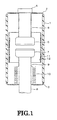
- Fig. 1 is a cross-sectional view showing the construction of a vacuum valve according to Embodiment 1 of the present invention.
- a fixed side sealing metal element (metal clasp) 2 and a movable side sealing metal element 3 are sealingly attached at both end apertures of a tubular vacuum insulating container 1 made of alumina ceramics.
- a fixed side conductive shaft 4 made of electrical copper is fixed by passing through the fixed side sealing metal element 2.
- a fixed side metallic coating 5 of higher melting point than the electrical copper, made of for example chromium, is provided by evaporation or plating. The coating thickness is a few hundred nm.
- a fixed side contact 6 comprising copper alloy is fixed at the end of the fixed side conductive shaft 4.
- a movable side contact 7 comprising copper alloy is fixed to the end of the movable side conductive shaft 8, which is made of electrical copper and which passes through the movable side sealing metal element 3 in freely movable fashion, so that these contacts can be freely opened/closed.
- a bellows 10 is sealingly attached at the middle section of the movable side conductive shaft 8, in such a way that it can freely extend/contract, the other end thereof being sealingly attached to the movable side sealing metal element 3.
- the movable side conductive shaft 8 can be moved in the axial direction while maintaining vacuum within the vacuum insulating container 1.
- the movable side metallic coating 9 need not be provided on the movable side conductive shaft 8 that is surrounded by the bellows 10.
- a tubular shield 11 made of stainless steel is fixed on the inside face of the vacuum insulating container 1 so as to surround the fixed side contact 6 and the movable side contact 7.
- a shield side metallic coating 12 made for example of chromium of higher melting point than the stainless steel is provided on the inside face of the arc shield 11 in the same way as in the case of the conductive shafts 4, 8.
- metallic coatings 5, 9 of for example chromium (melting point about 1900°C) that is higher than the melting point of electrical copper (about 1020°C) are provided, and, in the case of the arc shield 11, a metallic coating 12 that is of melting point higher than that of the stainless steel (about 1420°C) is provided: in this way, the withstand-voltage characteristic can be improved.
- the facing areas are largest within the vacuum valve between the conductive shafts 4, 8 and the arc shield 11, so that there is a tendency for the breakdown electric field to decrease due to the area effect, by providing metallic coatings 5, 9, 12 made of metal of melting point higher than the metal of which the aforementioned members are themselves constituted, the apparent breakdown electrical field can be increased.
- the metal of which the aforementioned members are constituted is electrical copper in the case of the conductive shafts 4, 8 and stainless steel in the case of the arc shield 11.
- FIG. 2 is a cross-sectional view showing the construction of a vacuum valve according to Embodiment 2 of the present invention.
- the point of difference of this Embodiment 2 from Embodiment 1 is the range over which the metallic coating is provided.
- constituent portions that are the same as in the case of Embodiment 1 are given the same reference symbols and further detailed description thereof is dispensed with.
- a fixed side electrode metallic coating 13 and movable side electrode metallic coating 14 like the metallic coatings 5, 9 are provided also on the peripheral sections of the fixed side contact 6 and movable side contact 7.
- the fixed side contact 6 and movable side contact 7 are constituted by for example a coil electrode and contactor that generate for example a longitudinal magnetic field: the electrical field at the outer face of the coil electrode is comparatively high.
- the metallic coatings 13, 14 are provided on the outside face of these coil electrodes.
- an end metallic coating 15 like the shield-side metallic coating 12 is provided at the end of the arc shield 11.
- metallic coatings 13, 14, 15 are also provided in portions where the electric field is high.
- these metallic coatings 13, 14, 15 have greater film thickness than the metallic coatings 5, 9, 12 provided on faces where the electric field intensity is low, so that their surfaces can be made smoother. Film thickness of a few ⁇ m to a few tens of ⁇ m can be achieved by employing ion plating. It should be noted that, taking into account electrical conductivity, the coil electrode is made of electrical copper.
- Fig. 3 is a cross-sectional view showing the construction of a vacuum valve according to Embodiment 3 of the present invention.
- the aspect in which this Embodiment 3 differs from Embodiment 2 is the provision of an insulating film at the periphery of the vacuum insulating container.
- structural portions that are the same as in the case of Embodiment 2 are given the same reference symbols and further detailed description thereof is dispensed with.
- an insulating layer 16 that is formed by molding epoxy resin is provided at the periphery of the vacuum insulating container 1.
- the withstand-voltage characteristic can be improved.
Landscapes
- High-Tension Arc-Extinguishing Switches Without Spraying Means (AREA)
Abstract
A vacuum valve having: a vacuum insulating container (1); a pair of contacts (6), (7) that can be freely opened/closed, accommodated in the vacuum insulating container (1); conductive shafts (4), (8) that are fixed to the contacts (6), (7); and an arc shield (11) provided so as to surround the contacts(6), (7), characterized in that a metallic coating (5), (9), (12) made of metallic material of melting point higher than the respective underlying metal thereof is provided on the outside face of the conductive shafts (4), (8) and the inside face of the arc shield (11).
Description
- Embodiments described herein relate generally to a vacuum valve having a pair of contacts that can be freely opened/closed, whereby improved withstand voltage characteristic or performance can be obtained.
- Vacuum valves of this type are previously known in which, in order to improved withstand-voltage performance in vacuum, a ceramic diffusion layer is generated at the end of a tubular arc shield that is used for preventing diffusion of metallic vapor. An example is disclosed in Laid-open Japanese Patent Application No.
2007-115599 - Vacuum valves are also known in which the withstand-voltage characteristic is improved by reducing the curvature for example at the end of the arc shield. In this case, the so-called area effect in vacuum is utilized and the breakdown field is increased by reducing the area that contributes to insulation breakdown. An example is disclosed in Laid-open Japanese Patent Application No.
H10-21802 - In the conventional vacuum valves described above, the portion of high electrical field intensity tends to be located at the end of the arc shield and various schemes for improving the withstand voltage are adopted. In contrast, in the case of conductive shafts with contacts fixed thereto, the insulation distance with respect to the arc shield is comparatively securely guaranteed, so the electric field intensity can be restrained. However, between the rod-shaped conductive shafts and the tubular arc shield, the area that contributes to insulation breakdown is much larger than in the case of the end of the arc shield, so, taking into account the "area in vacuum" effect, the breakdown electric field is lowered.
- In particular, in response to the demand for increased capacity and/or reduction in overall size, either the conductive shafts may be made of larger diameter or the insulation distance may be reduced, so the opposing areas are increased, lowering the breakdown electrical field. There is therefore the problem of lowering of the withstand voltage characteristic between the conductive shafts and the arc shield.
- According to an aspect of the present technology, there is provided a vacuum valve which aims to achieve increased capacity and/or smaller overall size by improvement in the withstand voltage characteristic between the conductive shafts and the arc shield.
- In order to achieve the above object, a vacuum valve according to an embodiment is constructed as follows. Specifically, a vacuum valve having:
- a vacuum insulating container;
- a pair of contacts that can be freely opened/closed, accommodated in said vacuum insulating container;
- conductive shafts fixed to aforementioned contacts; and
- an arc shield provided so as to surround aforementioned contacts
- is characterized in that the outside face of aforementioned conductive shafts and the inside face of aforementioned arc shield are provided with a metallic coating made of metallic material of higher melting point than the underlying metal (the constituent metal in question) thereof.
-
- [
Fig. 1 ] Cross-sectional view showing a vacuum valve according to Embodiment 1 of the present invention; - [
Fig. 2 ] Cross-sectional view showing a vacuum valve according toEmbodiment 2 of the present invention; and - [
Fig. 3 ] Cross-sectional view showing a vacuum valve according toEmbodiment 3 of the present invention. - In embodiments of the present invention, the breakdown electrical field in vacuum is increased by employing a metallic coating of high melting point. Embodiments of the present invention are described below with reference to the drawings.
- First of all, a vacuum valve according to Embodiment 1 of the present invention will be described with reference to
Fig. 1. Fig. 1 is a cross-sectional view showing the construction of a vacuum valve according to Embodiment 1 of the present invention. - As shown in
Fig. 1 , a fixed side sealing metal element (metal clasp) 2 and a movable side sealingmetal element 3 are sealingly attached at both end apertures of a tubular vacuum insulating container 1 made of alumina ceramics. A fixed sideconductive shaft 4 made of electrical copper is fixed by passing through the fixed side sealingmetal element 2. On the outside face of the fixed sideconductive shaft 4, a fixed sidemetallic coating 5 of higher melting point than the electrical copper, made of for example chromium, is provided by evaporation or plating. The coating thickness is a few hundred nm. A fixedside contact 6 comprising copper alloy is fixed at the end of the fixed sideconductive shaft 4. - Opposite the
fixed side contact 6, amovable side contact 7 comprising copper alloy is fixed to the end of the movable sideconductive shaft 8, which is made of electrical copper and which passes through the movable side sealingmetal element 3 in freely movable fashion, so that these contacts can be freely opened/closed. On the outside face of the movable sideconductive shaft 8, just as in the case of the fixed side, there is provided a movable sidemetallic coating 9 of higher melting point than the electrical copper. - One end of a
bellows 10 is sealingly attached at the middle section of the movable sideconductive shaft 8, in such a way that it can freely extend/contract, the other end thereof being sealingly attached to the movable side sealingmetal element 3. In this way, the movable sideconductive shaft 8 can be moved in the axial direction while maintaining vacuum within the vacuum insulating container 1. Incidentally, the movable sidemetallic coating 9 need not be provided on the movable sideconductive shaft 8 that is surrounded by thebellows 10. - Also, a
tubular shield 11 made of stainless steel is fixed on the inside face of the vacuum insulating container 1 so as to surround thefixed side contact 6 and themovable side contact 7. A shield sidemetallic coating 12 made for example of chromium of higher melting point than the stainless steel is provided on the inside face of thearc shield 11 in the same way as in the case of theconductive shafts - In this way, in the case of the
conductive shafts metallic coatings arc shield 11, ametallic coating 12 that is of melting point higher than that of the stainless steel (about 1420°C) is provided: in this way, the withstand-voltage characteristic can be improved. Specifically, although the facing areas are largest within the vacuum valve between theconductive shafts arc shield 11, so that there is a tendency for the breakdown electric field to decrease due to the area effect, by providingmetallic coatings conductive shafts arc shield 11. - It is believed that this improvement is achieved because minute surface irregularities formed during mechanical processing are smoothed out by the
metallic coatings metallic coatings - With the vacuum valve according to Embodiment 1 described above, by providing
metallic coatings conductive shafts arc shield 11, which are of large facing area, the withstand-voltage characteristic can be improved, making it possible to reduce the overall size. - Next, the vacuum valve according to
Embodiment 2 of the present invention will be described with reference toFig. 2. Fig. 2 is a cross-sectional view showing the construction of a vacuum valve according toEmbodiment 2 of the present invention. The point of difference of thisEmbodiment 2 from Embodiment 1 is the range over which the metallic coating is provided. InFig. 2 , constituent portions that are the same as in the case of Embodiment 1 are given the same reference symbols and further detailed description thereof is dispensed with. - As shown in
Fig. 2 , a fixed side electrodemetallic coating 13 and movable side electrodemetallic coating 14 like themetallic coatings side contact 6 andmovable side contact 7. The fixedside contact 6 andmovable side contact 7 are constituted by for example a coil electrode and contactor that generate for example a longitudinal magnetic field: the electrical field at the outer face of the coil electrode is comparatively high. Thus themetallic coatings metallic coating 15 like the shield-sidemetallic coating 12 is provided at the end of thearc shield 11. - Specifically,
metallic coatings metallic coatings metallic coatings - With the vacuum valve according to the
above Embodiment 2, sincemetallic coatings - Next, a vacuum valve according to
Embodiment 3 of the present invention will be described with reference toFig. 3 . -
Fig. 3 is a cross-sectional view showing the construction of a vacuum valve according toEmbodiment 3 of the present invention. The aspect in which thisEmbodiment 3 differs fromEmbodiment 2 is the provision of an insulating film at the periphery of the vacuum insulating container. InFig. 3 , structural portions that are the same as in the case ofEmbodiment 2 are given the same reference symbols and further detailed description thereof is dispensed with. - As shown in
Fig. 3 , an insulatinglayer 16 that is formed by molding epoxy resin is provided at the periphery of the vacuum insulating container 1. - With the vacuum valve according to
Embodiment 3, in addition to the beneficial effects ofembodiment 2, insulation reinforcement of the insulation along the surface of the outside of the vacuum insulating container 1 can be achieved by the insulatinglayer 16, thereby making it possible to further reduce the overall size of the vacuum valve. - With the embodiments described above, by providing a metallic coating made of metallic material of higher melting point than electrical copper on the conductive shafts, or by providing a metallic coating made of metallic material of higher melting point than stainless steel on the arc shield, the withstand-voltage characteristic can be improved.
- While various embodiments have been described above, these embodiments are merely given by way of example and are not intended to restrict the scope of the present invention. In fact, the novel device that is described herein could be realized in various other modes and various omissions, substitutions or alterations could be performed in the form of the device described herein without departing from the gist or spirit of the present invention. The appended claims and equivalents thereof are intended to include modes or modifications such as fall within the scope of the present invention and the gist or spirit thereof.
Claims (6)
- A vacuum valve comprising:a vacuum insulating container;a pair of contacts that can be freely opened/closed, accommodated in said vacuum insulating container;conductive shafts that are fixed to said contacts, andan arc shield provided so as to surround said contacts;characterized in that a metallic coating made of metallic material of melting point higher than an underlying metal thereof is provided on an outside face of said conductive shafts and an inside face of said arc shield.
- The vacuum valve according to claim 1, characterized in that said contacts comprise
contactors capable of being opened/closed; and
coil electrodes that generate a magnetic field and are fixed to said contactors,
wherein a metallic coating made of metallic material of higher melting point than said underlying metal is provided on the outside face of said coil electrodes. - The vacuum valve according to claim 1 or claim 2, characterized in that a metallic coating made of metal of higher melting point than said underlying metal is provided at an end of said arc shield.
- The vacuum valve according to any of claims 1 to 3, characterized in that said metallic coating contains at least one of chromium, titanium, or molybdenum.
- The vacuum valve according to any of claims 1 to 4, characterized in that said metallic coating is provided by ion plating.
- The vacuum valve according to any of claim 1 to claim 5, characterized in that an insulating layer is provided around said vacuum insulating container.
Applications Claiming Priority (1)
| Application Number | Priority Date | Filing Date | Title |
|---|---|---|---|
| JP2010158126A JP5537303B2 (en) | 2010-07-12 | 2010-07-12 | Vacuum valve |
Publications (1)
| Publication Number | Publication Date |
|---|---|
| EP2407991A1 true EP2407991A1 (en) | 2012-01-18 |
Family
ID=44652110
Family Applications (1)
| Application Number | Title | Priority Date | Filing Date |
|---|---|---|---|
| EP11173237A Withdrawn EP2407991A1 (en) | 2010-07-12 | 2011-07-08 | Vacuum valve |
Country Status (4)
| Country | Link |
|---|---|
| EP (1) | EP2407991A1 (en) |
| JP (1) | JP5537303B2 (en) |
| KR (1) | KR101254629B1 (en) |
| CN (1) | CN102332364B (en) |
Cited By (1)
| Publication number | Priority date | Publication date | Assignee | Title |
|---|---|---|---|---|
| EP4553878A1 (en) * | 2023-11-08 | 2025-05-14 | Abb Schweiz Ag | Vacuum interrupter with coated parts |
Families Citing this family (1)
| Publication number | Priority date | Publication date | Assignee | Title |
|---|---|---|---|---|
| JP2021048029A (en) * | 2019-09-18 | 2021-03-25 | 富士電機株式会社 | Vacuum valve |
Citations (9)
| Publication number | Priority date | Publication date | Assignee | Title |
|---|---|---|---|---|
| JPS53121173A (en) * | 1977-03-30 | 1978-10-23 | Tokyo Shibaura Electric Co | Vacuum breaker |
| GB2061010A (en) * | 1979-10-09 | 1981-05-07 | Meidensha Electric Mfg Co Ltd | Vacuum type circuit interrupter |
| EP0286335A1 (en) * | 1987-04-02 | 1988-10-12 | Kabushiki Kaisha Toshiba | Air-tight ceramic container |
| JPH09245589A (en) * | 1996-03-01 | 1997-09-19 | Toshiba Corp | Vacuum valve |
| JP2002319342A (en) * | 2001-04-19 | 2002-10-31 | Mitsubishi Electric Corp | Vacuum valve |
| EP1501101A2 (en) * | 2003-07-25 | 2005-01-26 | Kabushiki Kaisha Toshiba | Molded electric device and molding method thereof |
| WO2006032522A1 (en) * | 2004-09-25 | 2006-03-30 | Abb Technology Ag | Method for producing an arc-erosion resistant coating and corresponding shield for vacuum arcing chambers |
| WO2007031202A1 (en) * | 2005-09-13 | 2007-03-22 | Abb Technology Ag | Vacuum interrupter chamber |
| JP2007115599A (en) | 2005-10-21 | 2007-05-10 | Toshiba Corp | Vacuum valve |
Family Cites Families (9)
| Publication number | Priority date | Publication date | Assignee | Title |
|---|---|---|---|---|
| JPS60163322A (en) * | 1984-02-03 | 1985-08-26 | 三菱電機株式会社 | Vacuum breaker |
| JPS6455634U (en) * | 1987-09-30 | 1989-04-06 | ||
| JPH0821295B2 (en) * | 1990-09-05 | 1996-03-04 | 三菱電機株式会社 | Vacuum switch tube |
| JP3431319B2 (en) * | 1994-12-26 | 2003-07-28 | 株式会社東芝 | Electrode for vacuum valve |
| JP4004681B2 (en) * | 1999-04-05 | 2007-11-07 | 三菱電機株式会社 | Switchgear |
| JP2003203546A (en) * | 2002-01-09 | 2003-07-18 | Toshiba Corp | Mold vacuum switch |
| JP2004235121A (en) * | 2003-02-03 | 2004-08-19 | Japan Ae Power Systems Corp | Vacuum circuit breaker |
| JP5095591B2 (en) * | 2008-11-27 | 2012-12-12 | 株式会社東芝 | Vacuum valve |
| CN201364855Y (en) * | 2009-01-14 | 2009-12-16 | 湖北汉光科技股份有限公司 | Vacuum switch tube |
-
2010
- 2010-07-12 JP JP2010158126A patent/JP5537303B2/en active Active
-
2011
- 2011-07-07 KR KR1020110067133A patent/KR101254629B1/en not_active Expired - Fee Related
- 2011-07-08 EP EP11173237A patent/EP2407991A1/en not_active Withdrawn
- 2011-07-12 CN CN201110219982.XA patent/CN102332364B/en active Active
Patent Citations (9)
| Publication number | Priority date | Publication date | Assignee | Title |
|---|---|---|---|---|
| JPS53121173A (en) * | 1977-03-30 | 1978-10-23 | Tokyo Shibaura Electric Co | Vacuum breaker |
| GB2061010A (en) * | 1979-10-09 | 1981-05-07 | Meidensha Electric Mfg Co Ltd | Vacuum type circuit interrupter |
| EP0286335A1 (en) * | 1987-04-02 | 1988-10-12 | Kabushiki Kaisha Toshiba | Air-tight ceramic container |
| JPH09245589A (en) * | 1996-03-01 | 1997-09-19 | Toshiba Corp | Vacuum valve |
| JP2002319342A (en) * | 2001-04-19 | 2002-10-31 | Mitsubishi Electric Corp | Vacuum valve |
| EP1501101A2 (en) * | 2003-07-25 | 2005-01-26 | Kabushiki Kaisha Toshiba | Molded electric device and molding method thereof |
| WO2006032522A1 (en) * | 2004-09-25 | 2006-03-30 | Abb Technology Ag | Method for producing an arc-erosion resistant coating and corresponding shield for vacuum arcing chambers |
| WO2007031202A1 (en) * | 2005-09-13 | 2007-03-22 | Abb Technology Ag | Vacuum interrupter chamber |
| JP2007115599A (en) | 2005-10-21 | 2007-05-10 | Toshiba Corp | Vacuum valve |
Cited By (1)
| Publication number | Priority date | Publication date | Assignee | Title |
|---|---|---|---|---|
| EP4553878A1 (en) * | 2023-11-08 | 2025-05-14 | Abb Schweiz Ag | Vacuum interrupter with coated parts |
Also Published As
| Publication number | Publication date |
|---|---|
| JP2012022812A (en) | 2012-02-02 |
| CN102332364A (en) | 2012-01-25 |
| JP5537303B2 (en) | 2014-07-02 |
| CN102332364B (en) | 2015-02-25 |
| KR20120006447A (en) | 2012-01-18 |
| KR101254629B1 (en) | 2013-04-15 |
Similar Documents
| Publication | Publication Date | Title |
|---|---|---|
| US10134546B2 (en) | Maximizing wall thickness of a Cu—Cr floating center shield component by moving contact gap away from center flange axial location | |
| KR101100708B1 (en) | Vacuum breaker | |
| CN102959657A (en) | Vacuum variable capacitor | |
| JP2009240095A (en) | Vacuum breaker | |
| CN102292788A (en) | Vacuum switch tube | |
| JP5175516B2 (en) | Vacuum valve | |
| CN110168695A (en) | Electrical insulator based on aluminium oxide ceramics, the method for manufacturing the insulator and the vacuum tube including the insulator | |
| JP5197065B2 (en) | Vacuum valve | |
| JP5139179B2 (en) | Vacuum valve | |
| KR101254629B1 (en) | Vacuum valve | |
| JP5475601B2 (en) | Vacuum valve | |
| JP4703360B2 (en) | Vacuum valve | |
| JP4940020B2 (en) | Gas insulated switchgear | |
| JP5475559B2 (en) | Vacuum switchgear | |
| JP2019110010A (en) | Vacuum valve | |
| JP4291013B2 (en) | Vacuum valve | |
| US10840044B2 (en) | Ceramic insulator for vacuum interrupters | |
| WO2021110248A1 (en) | A bellows for a vacuum interrupter, exhaust compensator or valve | |
| CA1219624A (en) | Vacuum interrupter | |
| JP7446524B2 (en) | vacuum valve | |
| JP2025159886A (en) | vacuum valve | |
| JP5525364B2 (en) | Vacuum valve | |
| CN113474865B (en) | Vacuum circuit breaker | |
| JP2008282557A (en) | Vacuum switchgear | |
| JP7170499B2 (en) | vacuum valve |
Legal Events
| Date | Code | Title | Description |
|---|---|---|---|
| 17P | Request for examination filed |
Effective date: 20110708 |
|
| AK | Designated contracting states |
Kind code of ref document: A1 Designated state(s): AL AT BE BG CH CY CZ DE DK EE ES FI FR GB GR HR HU IE IS IT LI LT LU LV MC MK MT NL NO PL PT RO RS SE SI SK SM TR |
|
| AX | Request for extension of the european patent |
Extension state: BA ME |
|
| PUAI | Public reference made under article 153(3) epc to a published international application that has entered the european phase |
Free format text: ORIGINAL CODE: 0009012 |
|
| 17Q | First examination report despatched |
Effective date: 20150616 |
|
| STAA | Information on the status of an ep patent application or granted ep patent |
Free format text: STATUS: THE APPLICATION IS DEEMED TO BE WITHDRAWN |
|
| 18D | Application deemed to be withdrawn |
Effective date: 20151027 |