EP2407722A1 - High-frequency heating device with vapor generating function - Google Patents
High-frequency heating device with vapor generating function Download PDFInfo
- Publication number
- EP2407722A1 EP2407722A1 EP10761421A EP10761421A EP2407722A1 EP 2407722 A1 EP2407722 A1 EP 2407722A1 EP 10761421 A EP10761421 A EP 10761421A EP 10761421 A EP10761421 A EP 10761421A EP 2407722 A1 EP2407722 A1 EP 2407722A1
- Authority
- EP
- European Patent Office
- Prior art keywords
- heating chamber
- bottom wall
- chamber
- power feeding
- generating function
- Prior art date
- Legal status (The legal status is an assumption and is not a legal conclusion. Google has not performed a legal analysis and makes no representation as to the accuracy of the status listed.)
- Withdrawn
Links
Images



Classifications
-
- F—MECHANICAL ENGINEERING; LIGHTING; HEATING; WEAPONS; BLASTING
- F24—HEATING; RANGES; VENTILATING
- F24C—DOMESTIC STOVES OR RANGES ; DETAILS OF DOMESTIC STOVES OR RANGES, OF GENERAL APPLICATION
- F24C15/00—Details
- F24C15/32—Arrangements of ducts for hot gases, e.g. in or around baking ovens
- F24C15/322—Arrangements of ducts for hot gases, e.g. in or around baking ovens with forced circulation
- F24C15/327—Arrangements of ducts for hot gases, e.g. in or around baking ovens with forced circulation with air moisturising
-
- H—ELECTRICITY
- H05—ELECTRIC TECHNIQUES NOT OTHERWISE PROVIDED FOR
- H05B—ELECTRIC HEATING; ELECTRIC LIGHT SOURCES NOT OTHERWISE PROVIDED FOR; CIRCUIT ARRANGEMENTS FOR ELECTRIC LIGHT SOURCES, IN GENERAL
- H05B6/00—Heating by electric, magnetic or electromagnetic fields
- H05B6/64—Heating using microwaves
- H05B6/6402—Aspects relating to the microwave cavity
-
- H—ELECTRICITY
- H05—ELECTRIC TECHNIQUES NOT OTHERWISE PROVIDED FOR
- H05B—ELECTRIC HEATING; ELECTRIC LIGHT SOURCES NOT OTHERWISE PROVIDED FOR; CIRCUIT ARRANGEMENTS FOR ELECTRIC LIGHT SOURCES, IN GENERAL
- H05B6/00—Heating by electric, magnetic or electromagnetic fields
- H05B6/64—Heating using microwaves
- H05B6/647—Aspects related to microwave heating combined with other heating techniques
- H05B6/6473—Aspects related to microwave heating combined with other heating techniques combined with convection heating
- H05B6/6479—Aspects related to microwave heating combined with other heating techniques combined with convection heating using steam
Definitions
- the present invention relates to a high-frequency heating device with a vapor generating function.
- microwave oven 1 serving as a high-frequency heating device has: chassis 2 in a substantially rectangular parallelepiped shape made of a metal plate; heating chamber 3 having an opening on its front face; and door 4 opening and closing the opening.
- heating chamber 3 five wall faces excluding the opening are made up of metal plates.
- a depressed section (not shown) is formed on a bottom wall of heating chamber 3.
- a space in the depressed section is power feeding chamber 5.
- Partition plate 6 is installed on an opening of power feeding chamber 5, namely an opening of the depressed section formed on the bottom wall of heating chamber 3. That is, heating chamber 3 and power feeding chamber 5 provided below and adjacent to heating chamber 3 are partitioned by partition plate 6.
- Partition plate 6 is formed of a material which allows high-frequency energy to pass therethrough.
- Partition plate 6 is formed, for example, of glass or ceramic.
- Microwave oven 1 has a magnetron (not shown) constituting the high-frequency generator, outside the sidewall face of heating chamber 3. Further, microwave oven 1 has a cooling fan (not shown) for cooling heat generated during operations of the magnetron or power supply circuit components which supply the magnetron with electric power.
- microwave oven 1 First, a user of microwave oven 1 places an object to be heated on partition plate 6 in heating chamber 3, and then operates an operation panel (not shown) provided in a lower section of door 4.
- a high frequency electromagnetic wave is generated from the magnetron.
- the high frequency electromagnetic wave propagates through a waveguide (not shown), to be introduced into power feeding chamber 5.
- the high-frequency electromagnetic wave introduced into power feeding chamber 5 is dispersed by the stirring blade (antenna), and passes through partition plate 6, to be absorbed into the object to be heated and converted to heat.
- partition plate 6 On a bottom face of heating chamber 3, partition plate 6 is provided on the opening side while steam generating section 11 is provided on the back side, both being provided in contact with each other. Steam generating section 11 is provided with evaporation tray 8 which heats water fed from the outside of heating chamber 3 for evaporation.
- Joint section 9 of power feeding chamber 5 with right and left sidewalls 7 and evaporation tray 8 of heating chamber 3 is located at a position identical to or lower than partition plate 6. Therefore, at the time of the user of microwave oven 1 taking the object to be heated into or out of heating chamber 3 or during heating of the object to be heated, water or oil in the object to be heated may overflow or spatter. When the water or the oil flows from a gap between partition plate 6 and the wall faces of heating chamber 3 downward, namely into power feeding chamber 5, a component such as the stirring blade (antenna) or the motor may fail.
- power feeding chamber 5 and evaporation tray 8 are made up of different components, a gap tends to be generated in joint section 9 between a component constituting power feeding chamber 5 and a component constituting evaporation tray 8. For this reason, in the case of feeding water until completion of cooking or in the case of performing an operation to cancel cooking using steam immediately after the start of this cooking and then restarting the cooking using steam, water may be excessively fed to evaporation tray 8 and water may overflow from evaporation tray 8. The water having overflowed from evaporation tray 8 passes through joint section 9 between evaporation tray 8 and partition plate 6 and enters into power feeding chamber 5. When a spark is generated for this reason from the component such as the stirring blade (antenna) or the motor, it may cause a failure.
- the component such as the stirring blade (antenna) or the motor
- Patent Document 1 Unexamined Japanese Patent Publication No. 2008-224078
- the present invention provides a high-frequency heating device with a vapor generating function, which is easy to manufacture and capable of preventing failure due to leakage of water or oil from an evaporation tray or an object to be heated.
- the high-frequency heating device with the vapor generating function in the present invention is provided with: a metallic heating chamber having an opening in its front face and accommodating an object to be heated; and door for opening and closing the opening of the heating chamber. Further, the high-frequency heating device with the vapor generating function in the present invention is provided with: a power feeding chamber provided below and adjacent to the heating chamber and having an opening in its upper portion; and a partition plate closing the opening of the power feeding chamber and partitioning between the heating chamber and the power feeding chamber, and for supporting the object to be heated. Moreover, the high-frequency heating device with the vapor generating function in the present invention is provided with: an evaporation tray formed in the heating chamber; and a high-frequency generator generating a high-frequency electromagnetic wave. Furthermore, in the high-frequency heating device with the vapor generating function, right and left sidewalls and a bottom wall of the heating chamber are unitarily configured without seams.
- FIG. 1 is a front perspective view of a high-frequency heating device with a vapor generating function in Embodiment 1 of the present invention.
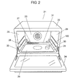
- FIG. 2 is a front perspective view of the high-frequency heating device with the vapor generating function in the embodiment, installed with a partition plate.
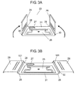
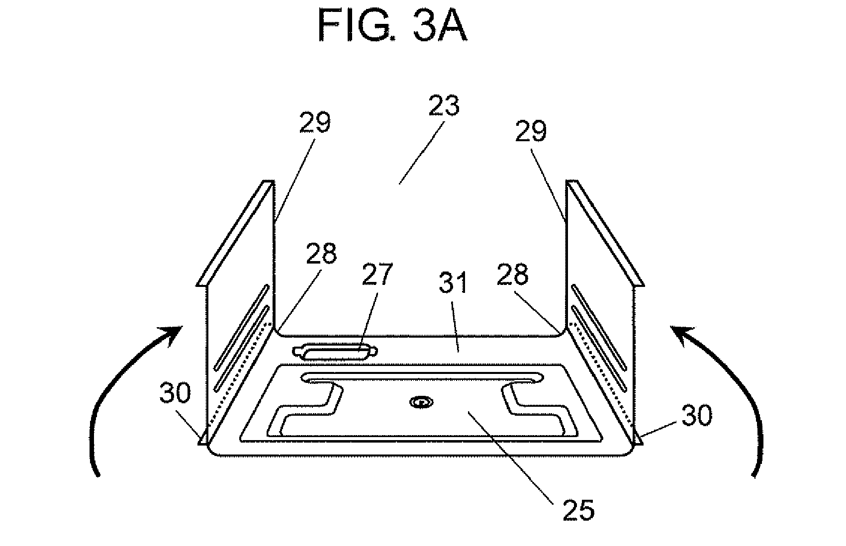
- FIGS. 3A and 3B are perspective views showing an assembled state of right and left sidewalls of a heating chamber and a bottom wall of the heating chamber.
- a body of microwave oven 21 as the high-frequency heating device with the vapor generating function is made up of chassis 22.
- chassis 22 metallic heating chamber 23 is formed.
- Heating chamber 23 has an opening on its front face, and door 24 is pivotally supported thereon in an openable/closable manner.
- a depressed section (not shown) is formed on bottom wall 31 of heating chamber 23.
- a space in the depressed section is power feeding chamber 25. That is, power feeding chamber 25 is provided adjacent to heating chamber 23.
- power feeding chamber 25 has a bottom face and side faces.
- Partition plate 26 is removably installed so as to close the opening of power feeding chamber 25.
- partition plate 26 partitions power feeding chamber 25 and heating chamber 23 which are provided adjacent to each other.
- Partition plate 26 is formed of a material which allows high-frequency energy to pass therethrough, such as glass or ceramic.
- a depressed section is formed having a substantially H shape in a planar view.
- the H-shaped depressed section is symmetrical. Making the shape of power feeding chamber 25 symmetrical can render favorable distributions of high-frequency electromagnetic waves in power feeding chamber 25 and heating chamber 23.
- magnetron 100 constituting the high-frequency generator is installed below power feeding chamber 25, namely outside the bottom face of power feeding chamber 25.
- the H-shaped depressed section on the bottom face of power feeding chamber 25 is configured to protrude downward from power feeding chamber 25. Arranging a component such as magnetron 100 in a portion below power feeding chamber 25 and other than the H-shaped depressed section can reduce a height of the bottom face of heating chamber 23. Further, this can suppress a total height of microwave oven 21
- a metallic stirring blade (not shown) is rotatably pivotally supported by a motor (not shown).
- the stirring blade functions as a high-frequency antenna, and uniformly distributes high-frequency energy.
- the high frequency electromagnetic wave generated from magnetron 100 propagates through a waveguide (not shown), to be introduced into power feeding chamber 25.
- the high-frequency electromagnetic wave introduced into power feeding chamber 25 is dispersed by the stirring blade (antenna), and passes through partition plate 26, to be absorbed into the object to be heated and converted to heat. The object to be heated is thereby heated.
- Evaporation tray 27 which heats water supplied from the outside of heating chamber 23 for evaporation is formed on the bottom face of heating chamber 23 and on the back side of power feeding chamber 25.
- Evaporation tray 27 has a depressed shape for pooling water, and formed on bottom wall 31 of heating chamber 23.
- Right and left sidewalls 29 and bottom wall 3 lof heating chamber 23 are formed by processing one metal plate as shown in FIGS. 3A and 3B . Thereby, an edge portion of the opening of power feeding chamber 25 and an edge portion of evaporation tray 27 are unitarily provided without seams.
- Both right and left side portions of bottom wall 31 of heating chamber 23 are bent and extend upward from curved face sections 28 formed in corner portions in the vicinities of right and left sidewalls 29 of heating chamber 23, to be connected with right and left sidewalls 29 of heating chamber 23.
- Curved face section 28 has an arc shape, for example.
- Right and left sidewalls 29 and bottom wall 31 of heating chamber 23 shown in FIG. 3A are formed by bending the right and left of one metal plate shown in FIG. 3B .
- An arrow in FIG. 3A shows a bending direction.
- the metal plate is, for example, a precoated steel plate.
- the precoated steel plate is processed by being bent by pressing.
- right and left sidewalls 29 of heating chamber 23 and bottom wall 31 of heating chamber 23 are unitarily formed without seams via curved face sections 28.
- perforation 101 extending in a direction toward the back of heating chamber 23 is provided on the top of curved face section 28, namely bent section 30 as a bent line.
- the precoated steel plate is bent along perforation 101. That is, right and left sidewalls 29 and bottom wall 31 of heating chamber 23 are connected via bent section 30.
- right and left sidewalls 29 of heating chamber 23 and bottom wall 31 of heating chamber 23 are formed via curved face sections 28.
- curved face section 28 for example having the arc shape, bent sections 30 between right and left sidewalls 29 of heating chamber 23 and bottom wall 31 of heating chamber 23 are provided at higher positions than evaporation tray 27.
- a ceiling wall (not shown) constituting a ceiling of heating chamber 23 and a back wall (not shown) thereof are unitarily formed in a similar manner to sidewalls 29 and bottom wall 31 described above. That is, a steel plate constituting the ceiling wall and the back wall is squeezed by pressing, cut off, punched, and installed with an ancillary component such as a cover for a heater, which is coated so as to have a self-cleaning effect and then bent. In this manner, the ceiling wall and the back wall are unitarily formed. Unitarily formed sidewalls 29 and bottom wall 31 and the unitarily formed ceiling wall and back wall are joined, to constitute heating chamber 23. It should be noted that, although the case has been described where the steel plate unitarily forming the ceiling wall and the back wall is coated after pressing, the precoated steel plate can be used as in the case of sidewalls 29 and bottom wall 31.
- a user of microwave oven 21 places an object to be heated on partition plate 26 in heating chamber 23, and then operates an operation panel (not shown) provided in a lower section of door 24.
- a high frequency electromagnetic wave is generated from magnetron 100.
- the high frequency electromagnetic wave propagates through a waveguide (not shown), to be introduced into power feeding chamber 25.
- the high-frequency electromagnetic wave introduced into power feeding chamber 25 is dispersed by the stirring blade (antenna), passes through partition plate 26 and is absorbed into the object to be heated. The object to be heated is thereby heated, and then cooked.
- water is fed from the outside of heating chamber 23 to evaporation tray 27 of heating chamber 23.
- Water pooled in evaporation tray 27 is heated by a heater (not shown) or the high-frequency electromagnetic wave, to turns to steam.
- water is dielectrically heated by use of a high-frequency electromagnetic wave in a band of 2450 MHz, to generate steam.
- microwave oven 21 of the present embodiment does not have a joint section between evaporation tray 27 and partition plate 26 nor joint sections between right and left sidewalls 29 of heating chamber 23 and bottom wall 31 of heating chamber 23. That is, even in the case of overflow of water from evaporation tray 27, water does not enter into power feeding chamber 25. Similarly, water or oil having spattered from the object to be heated does not enter into power feeding chamber 25. For this reason, a spark generated from a component such as the stirring blade (antenna) or the motor is suppressed, to reduce the possibility for a failure.
- bent sections 30 between right and left sidewalls 29 of heating chamber 23 and power feeding chamber 25 are provided at higher positions than evaporation tray 27.
- evaporation tray 27 Even when water pooled in evaporation tray 27 overflows, or when water or oil flows out in large amount from the object to be heated, the water or the oil is unlikely to be leaked from the perforated line of bent section 30.
- corner portions in the vicinities of bent sections 30 between right and left sidewalls 29 of heating chamber 23 and power feeding chamber 25 are arc-shaped curved face sections 28. This allows curved face section 28 to resist accumulation of dust. Further, even in the case of accumulation of dust in curved face section 28, removal of the dust is easy due to curved face section 28 having the arc shape. That is, heating chamber 23 is easy to clean, and the inside of heating chamber 23 can thus be kept clean.
- microwave oven 21 of the present embodiment does not have joint sections between right and left sidewalls 29 of heating chamber 23 and bottom wall 31 of heating chamber 23 nor a joint section between evaporation tray 27 and power feeding chamber 25. That is, right and left sidewalls 29 of heating chamber 23 and bottom wall 31 of heating chamber 23 are unitarily formed without seams. Further, an edge of evaporation tray 27 and an edge of power feeding chamber 25 are unitarily configured without seams.
- a sealing component and a sealing operation having been required in the conventional microwave oven, are not required. This can simplify the configuration, and also facilitate manufacturing due to reduction in number of components. That is, the productivity increases.
- water or oil is prevented from entering into power feeding chamber 25 and below power feeding chamber 25. This prevents failure of the component such as the stirring blade or the motor in microwave oven 21 of the present embodiment.
- heating chamber 23 eliminating the joint sections of heating chamber 23 can prevent electromagnetic wave leakage and hot air leakage from the joint section. Further, unitarily constituting heating chamber 23 without seams as thus described leads to improvement in strength of heating chamber 23 and improvement in reliability.
- FIGS. 4A and 4B are perspective views showing an assembled state of right and left sidewalls of a heating chamber and a bottom wall of the heating chamber in a high-frequency heating device with a vapor generating function in Embodiment 2 of the present invention.
- FIG. 5 is an expanded perspective view of a section A in FIG. 4B .
- FIG. 6 is an exploded perspective view of the heating chamber. It is to be noted that the same constitutional component as in Embodiment 1 is provided with the same numeral, and its detailed description is omitted.
- Right and left sidewalls 42 and bottom wall 45 of heating chamber 23 shown in FIG. 4A is formed by bending the right and left of one metal plate shown in FIG. 4B .
- An arrow in FIG. 4A shows a bending direction. That is, lower sides 44 of sidewalls 42 and right and left sides 46 of bottom wall 45 are folded to form heating chamber 23. This folded portion is folded section 40.
- bent section 49 is formed with a plurality of slits 48 at predetermined intervals.
- Slit 48 has a substantially isosceles trapezoid shape, and is formed by pressing.
- a longitudinal size of slit 48 and an interval between adjacent slits 48 are decided based on the easiness of manual folding processing at the time of producing folded section 40.
- the folding processing can be performed by small force at the time of producing folded section 40.
- the longitudinal size of slit 48 is made short, or when the interval between slits 48 is made long, large force is required for the folding processing.
- force required for formation of folded section 40 can be adjusted by adjusting the longitudinal size of slit 48 and the interval between slits 48.
- the size of slit 48 having the substantially isosceles trapezoid shape can be set to an upper base of 7 to 20 mm, a lower base of 2 mm 9 to 22 mm (the lower base is set longer than upper base by 2 mm), a height of 1.5 mm, and an interval of 3.7 mm.
- a manufacturing method for the high-frequency heating device with the vapor generating function as thus been configured is described.
- right and left sidewalls 42 of heating chamber 23 and bottom wall 45 of heating chamber 23 are unitarily formed by pressing, without seams.
- slits 48 in the isosceles trapezoid shape are formed in bent section 49 between sidewalls 42 and bottom wall 45. Slit 48 is formed in alignment such that its long side is along a folded direction.
- the precoated steel plate is bent to substantially 90 degrees, with the long sides of slits 48 as a bent line.
- ceiling wall 50 of heating chamber 23 and back wall 51 of heating chamber 23 are unitarily formed without seams as in the case of sidewalls 42 and bottom wall 45.
- a folded portion formed in folding of ceiling wall 50 and back wall 51 is folded section 52.
- Sidewalls 42 and bottom wall 45 as thus formed are combined with ceiling wall 50 and back wall 51 as thus formed, to produce heating chamber 23 having an opening on its front.
- lower sides 44 of right and left sidewalls 42 of heating chamber 23 and right and left sides 46 of bottom wall 45 of heating chamber 23 are folded, to improve the strength of heating chamber 23. Further, lower sides 44 of right and left sidewalls 42 of heating chamber 23 and right and left sides 46 of bottom wall 45 of heating chamber 23 are respectively connected via bent sections 49. Bent section 49 is formed with a plurality of slits 48 at predetermined intervals. It is thereby possible to manually perform bending processing without using a jig. In this manner, it is possible to manually produce heating chamber 23. That is, the production is possible without using a pressing machine, thereby to improve the productivity.
- folded sections 40 of lower sides 44 of right and left sidewalls 42 of heating chamber 23 and right and left sides 46 of bottom wall 45 of heating chamber 23 are formed by caulking.
- the strength of heating chamber 23 improves, and leakage of an electromagnetic wave and hot air from slit 48 are prevented. That is, the reliability and the cooking performance of microwave oven 21 are improved.
- right and left sidewalls 42 and bottom wall 45 being made up of one component, a material loss is reduced as compared with the case of performing pressing on right and left sidewalls 42 and bottom wall 45 as separate components. Furthermore, with right and left sidewalls 42 and bottom wall 45 being connected via bent sections 49, the strengths between right and left sidewalls 42 and bottom wall 45 are improved, and leakage of electromagnetic waves from between right and left sidewalls 42 and bottom wall 45 is reduced.
- slit 48 having the substantially isosceles trapezoid shape has been used in the present embodiment
- slit 48 having a rectangular shape may also be used.
- Slit 48 having the rectangular shape is used in a place where the accuracy of bending may be allowed to be low.
- folded section 52 between ceiling wall 50 and back wall 51 of heating chamber 23 is difficult to see from the user using microwave oven 21. Therefore, slit 48 having the rectangular shape can be used.
- the size of slit 48 having the rectangular shape can be set to a short side of 1.5 mm and a long side of 4.5 to 11 mm.
- the present invention is capable of preventing, with a simple configuration, leakage of water or oil from a heating chamber. Accordingly, it is applicable to a heating cooker in which water or oil is generated from an object to be heated.
Landscapes
- Physics & Mathematics (AREA)
- Electromagnetism (AREA)
- Engineering & Computer Science (AREA)
- Chemical & Material Sciences (AREA)
- Combustion & Propulsion (AREA)
- Mechanical Engineering (AREA)
- General Engineering & Computer Science (AREA)
- Electric Ovens (AREA)
- Constitution Of High-Frequency Heating (AREA)
Abstract
Description
- The present invention relates to a high-frequency heating device with a vapor generating function.
- An example of a conventional high-frequency heating device with a vapor generating function is shown in
FIGS. 7 and 8 . InFIGS. 7 and 8 ,microwave oven 1 serving as a high-frequency heating device has:chassis 2 in a substantially rectangular parallelepiped shape made of a metal plate;heating chamber 3 having an opening on its front face; anddoor 4 opening and closing the opening. - In
heating chamber 3, five wall faces excluding the opening are made up of metal plates. On a bottom wall ofheating chamber 3, a depressed section (not shown) is formed. A space in the depressed section ispower feeding chamber 5.Partition plate 6 is installed on an opening ofpower feeding chamber 5, namely an opening of the depressed section formed on the bottom wall ofheating chamber 3. That is,heating chamber 3 andpower feeding chamber 5 provided below and adjacent toheating chamber 3 are partitioned bypartition plate 6.Partition plate 6 is formed of a material which allows high-frequency energy to pass therethrough.Partition plate 6 is formed, for example, of glass or ceramic. - In
power feeding chamber 5, a metallic stirring blade (not shown) is rotatably pivotally supported by a motor (not shown). The stirring blade functions as a high-frequency antenna, and uniformly distributes high-frequency energy.Microwave oven 1 has a magnetron (not shown) constituting the high-frequency generator, outside the sidewall face ofheating chamber 3. Further,microwave oven 1 has a cooling fan (not shown) for cooling heat generated during operations of the magnetron or power supply circuit components which supply the magnetron with electric power. - Next, an operation of
microwave oven 1 is described. First, a user ofmicrowave oven 1 places an object to be heated onpartition plate 6 inheating chamber 3, and then operates an operation panel (not shown) provided in a lower section ofdoor 4. Herewith, a high frequency electromagnetic wave is generated from the magnetron. The high frequency electromagnetic wave propagates through a waveguide (not shown), to be introduced intopower feeding chamber 5. The high-frequency electromagnetic wave introduced intopower feeding chamber 5 is dispersed by the stirring blade (antenna), and passes throughpartition plate 6, to be absorbed into the object to be heated and converted to heat. - On a bottom face of
heating chamber 3,partition plate 6 is provided on the opening side whilesteam generating section 11 is provided on the back side, both being provided in contact with each other.Steam generating section 11 is provided withevaporation tray 8 which heats water fed from the outside ofheating chamber 3 for evaporation. -
Joint section 9 ofpower feeding chamber 5 with right andleft sidewalls 7 andevaporation tray 8 ofheating chamber 3 is located at a position identical to or lower thanpartition plate 6. Therefore, at the time of the user ofmicrowave oven 1 taking the object to be heated into or out ofheating chamber 3 or during heating of the object to be heated, water or oil in the object to be heated may overflow or spatter. When the water or the oil flows from a gap betweenpartition plate 6 and the wall faces ofheating chamber 3 downward, namely intopower feeding chamber 5, a component such as the stirring blade (antenna) or the motor may fail. - In order to avoid such an inconvenience, there has been a configuration where the gap between
partition plate 6 and the wall faces ofheating chamber 3 is watertightly sealed (e.g. see Patent Document 1). Describing this by use ofFIG. 8 , there has been a configuration wherepartition plate 6 is placed onheating chamber 3, and thereafter, a gap ofjoint section 9 all aroundpartition plate 6 is filled withsealant 10 having adhesion properties, such as silicone rubber, to fixpartition plate 6. However, in such a configuration where the gap betweenpartition plate 6 and the wall faces ofheating chamber 3 is filled withsealant 10 tofix partition plate 6, thepartition plate 6 cannot be removed. Therefore, in the case of performing repairing,partition plate 6 needs to be destroyed orsealant 10 be cut out. That is, for repairing, a replacement component is required, and a long time is required for a repairing operation. - Further, since
power feeding chamber 5 andevaporation tray 8 are made up of different components, a gap tends to be generated injoint section 9 between a component constitutingpower feeding chamber 5 and a component constitutingevaporation tray 8. For this reason, in the case of feeding water until completion of cooking or in the case of performing an operation to cancel cooking using steam immediately after the start of this cooking and then restarting the cooking using steam, water may be excessively fed toevaporation tray 8 and water may overflow fromevaporation tray 8. The water having overflowed fromevaporation tray 8 passes throughjoint section 9 betweenevaporation tray 8 andpartition plate 6 and enters intopower feeding chamber 5. When a spark is generated for this reason from the component such as the stirring blade (antenna) or the motor, it may cause a failure. - In order to avoid such an inconvenience, it has been necessary to provide sealing to
joint section 9. However, providing the sealing makes the configuration complicated. That is, the workability in assembly deteriorates, or the number of steps of an assembly operation and cost of components increase due to the increased number of components. - [Patent Document 1] Unexamined Japanese Patent Publication No.
2008-224078 - The present invention provides a high-frequency heating device with a vapor generating function, which is easy to manufacture and capable of preventing failure due to leakage of water or oil from an evaporation tray or an object to be heated.
- The high-frequency heating device with the vapor generating function in the present invention is provided with: a metallic heating chamber having an opening in its front face and accommodating an object to be heated; and door for opening and closing the opening of the heating chamber. Further, the high-frequency heating device with the vapor generating function in the present invention is provided with: a power feeding chamber provided below and adjacent to the heating chamber and having an opening in its upper portion; and a partition plate closing the opening of the power feeding chamber and partitioning between the heating chamber and the power feeding chamber, and for supporting the object to be heated. Moreover, the high-frequency heating device with the vapor generating function in the present invention is provided with: an evaporation tray formed in the heating chamber; and a high-frequency generator generating a high-frequency electromagnetic wave. Furthermore, in the high-frequency heating device with the vapor generating function, right and left sidewalls and a bottom wall of the heating chamber are unitarily configured without seams.
- With this configuration, there are no joint sections between the right and left sidewall and the bottom wall of the heating chamber, and sealing is unnecessary. This facilitates manufacturing. Further, since there are no joint sections, even when water overflows from the evaporation tray, or when water or oil is generated from the object to be heated, the water or the oil is not leaked into the power feeding chamber so that failure can be prevented.
-
-
FIG. 1 is a front perspective view of a high-frequency heating device with a vapor generating function inEmbodiment 1 of the present invention. -
FIG. 2 is a front perspective view of the high-frequency heating device with the vapor generating function in the embodiment, installed with a partition plate. -
FIG. 3A is a perspective view showing an assembled state of right and left sidewalls of a heating chamber and a bottom wall of the heating chamber. -
FIG. 3B is a perspective view showing the assembled state of the right and left sidewalls of the heating chamber and the bottom wall of the heating chamber. -
FIG. 4A is a perspective view showing an assembled state of right and left sidewalls of a heating chamber and a bottom wall of the heating chamber in a high-frequency heating device with a vapor generating function inEmbodiment 2 of the present invention. -
FIG. 4B is a perspective view showing the assembled state of the right and left sidewalls of the heating chamber and the bottom wall of the heating chamber in the high-frequency heating device with the vapor generating function inEmbodiment 2 of the present invention. -
FIG. 5 is an expanded perspective view of a section A inFIG. 4B . -
FIG. 6 is an exploded perspective view of the heating chamber. -
FIG. 7 is a front perspective view of a conventional high-frequency heating device with a vapor generating function. -
FIG. 8 is a perspective view of a bottom wall of a heating chamber in the conventional high-frequency heating device with the vapor generating function. -
FIG. 1 is a front perspective view of a high-frequency heating device with a vapor generating function inEmbodiment 1 of the present invention.FIG. 2 is a front perspective view of the high-frequency heating device with the vapor generating function in the embodiment, installed with a partition plate.FIGS. 3A and 3B are perspective views showing an assembled state of right and left sidewalls of a heating chamber and a bottom wall of the heating chamber. - In
FIGS. 1 and2 , a body ofmicrowave oven 21 as the high-frequency heating device with the vapor generating function is made up ofchassis 22. Inchassis 22,metallic heating chamber 23 is formed.Heating chamber 23 has an opening on its front face, anddoor 24 is pivotally supported thereon in an openable/closable manner. Onbottom wall 31 ofheating chamber 23, a depressed section (not shown) is formed. A space in the depressed section ispower feeding chamber 25. That is,power feeding chamber 25 is provided adjacent toheating chamber 23. - Being in the depressed shape,
power feeding chamber 25 has a bottom face and side faces.Partition plate 26 is removably installed so as to close the opening ofpower feeding chamber 25. In other words,partition plate 26 partitionspower feeding chamber 25 andheating chamber 23 which are provided adjacent to each other.Partition plate 26 is formed of a material which allows high-frequency energy to pass therethrough, such as glass or ceramic. - On the bottom face of
power feeding chamber 25, a depressed section is formed having a substantially H shape in a planar view. The H-shaped depressed section is symmetrical. Making the shape ofpower feeding chamber 25 symmetrical can render favorable distributions of high-frequency electromagnetic waves inpower feeding chamber 25 andheating chamber 23. Meanwhile,magnetron 100 constituting the high-frequency generator is installed belowpower feeding chamber 25, namely outside the bottom face ofpower feeding chamber 25. Herein, the H-shaped depressed section on the bottom face ofpower feeding chamber 25 is configured to protrude downward frompower feeding chamber 25. Arranging a component such asmagnetron 100 in a portion belowpower feeding chamber 25 and other than the H-shaped depressed section can reduce a height of the bottom face ofheating chamber 23. Further, this can suppress a total height ofmicrowave oven 21 - In
power feeding chamber 25, a metallic stirring blade (not shown) is rotatably pivotally supported by a motor (not shown). The stirring blade functions as a high-frequency antenna, and uniformly distributes high-frequency energy. The high frequency electromagnetic wave generated frommagnetron 100 propagates through a waveguide (not shown), to be introduced intopower feeding chamber 25. The high-frequency electromagnetic wave introduced intopower feeding chamber 25 is dispersed by the stirring blade (antenna), and passes throughpartition plate 26, to be absorbed into the object to be heated and converted to heat. The object to be heated is thereby heated. -
Evaporation tray 27 which heats water supplied from the outside ofheating chamber 23 for evaporation is formed on the bottom face ofheating chamber 23 and on the back side ofpower feeding chamber 25.Evaporation tray 27 has a depressed shape for pooling water, and formed onbottom wall 31 ofheating chamber 23. - Right and left
sidewalls 29 andbottom wall 3lof heating chamber 23 are formed by processing one metal plate as shown inFIGS. 3A and 3B . Thereby, an edge portion of the opening ofpower feeding chamber 25 and an edge portion ofevaporation tray 27 are unitarily provided without seams. Both right and left side portions ofbottom wall 31 ofheating chamber 23 are bent and extend upward fromcurved face sections 28 formed in corner portions in the vicinities of right and left sidewalls 29 ofheating chamber 23, to be connected with right and left sidewalls 29 ofheating chamber 23.Curved face section 28 has an arc shape, for example. - Right and left
sidewalls 29 andbottom wall 31 ofheating chamber 23 shown inFIG. 3A are formed by bending the right and left of one metal plate shown inFIG. 3B . An arrow inFIG. 3A shows a bending direction. The metal plate is, for example, a precoated steel plate. The precoated steel plate is processed by being bent by pressing. Hence right and left sidewalls 29 ofheating chamber 23 andbottom wall 31 ofheating chamber 23 are unitarily formed without seams viacurved face sections 28. It is to be noted thatperforation 101 extending in a direction toward the back ofheating chamber 23 is provided on the top ofcurved face section 28, namely bentsection 30 as a bent line. The precoated steel plate is bent alongperforation 101. That is, right and leftsidewalls 29 andbottom wall 31 ofheating chamber 23 are connected viabent section 30. - Herein, right and left sidewalls 29 of
heating chamber 23 andbottom wall 31 ofheating chamber 23 are formed viacurved face sections 28. Withcurved face section 28 for example having the arc shape,bent sections 30 between right and left sidewalls 29 ofheating chamber 23 andbottom wall 31 ofheating chamber 23 are provided at higher positions thanevaporation tray 27. - A ceiling wall (not shown) constituting a ceiling of
heating chamber 23 and a back wall (not shown) thereof are unitarily formed in a similar manner to sidewalls 29 andbottom wall 31 described above. That is, a steel plate constituting the ceiling wall and the back wall is squeezed by pressing, cut off, punched, and installed with an ancillary component such as a cover for a heater, which is coated so as to have a self-cleaning effect and then bent. In this manner, the ceiling wall and the back wall are unitarily formed. Unitarily formed sidewalls 29 andbottom wall 31 and the unitarily formed ceiling wall and back wall are joined, to constituteheating chamber 23. It should be noted that, although the case has been described where the steel plate unitarily forming the ceiling wall and the back wall is coated after pressing, the precoated steel plate can be used as in the case ofsidewalls 29 andbottom wall 31. - An operation and a function of the high-frequency heating device with the vapor generating function as thus been configured are described.
- A user of
microwave oven 21 places an object to be heated onpartition plate 26 inheating chamber 23, and then operates an operation panel (not shown) provided in a lower section ofdoor 24. Herewith, a high frequency electromagnetic wave is generated frommagnetron 100. The high frequency electromagnetic wave propagates through a waveguide (not shown), to be introduced intopower feeding chamber 25. The high-frequency electromagnetic wave introduced intopower feeding chamber 25 is dispersed by the stirring blade (antenna), passes throughpartition plate 26 and is absorbed into the object to be heated. The object to be heated is thereby heated, and then cooked. - Herein, when cooking using steam is started, water is fed from the outside of
heating chamber 23 toevaporation tray 27 ofheating chamber 23. Water pooled inevaporation tray 27 is heated by a heater (not shown) or the high-frequency electromagnetic wave, to turns to steam. In addition, water is dielectrically heated by use of a high-frequency electromagnetic wave in a band of 2450 MHz, to generate steam. - In the case of feeding water until completion of cooking or in the case of performing an operation to cancel cooking using steam immediately after the start of this cooking and then restarting the cooking using steam, water may be excessively fed to
evaporation tray 27 and water may overflow fromevaporation tray 27. Herein,microwave oven 21 of the present embodiment does not have a joint section betweenevaporation tray 27 andpartition plate 26 nor joint sections between right and left sidewalls 29 ofheating chamber 23 andbottom wall 31 ofheating chamber 23. That is, even in the case of overflow of water fromevaporation tray 27, water does not enter intopower feeding chamber 25. Similarly, water or oil having spattered from the object to be heated does not enter intopower feeding chamber 25. For this reason, a spark generated from a component such as the stirring blade (antenna) or the motor is suppressed, to reduce the possibility for a failure. - Further,
bent sections 30 between right and left sidewalls 29 ofheating chamber 23 andpower feeding chamber 25 are provided at higher positions thanevaporation tray 27. Herewith, even when water pooled inevaporation tray 27 overflows, or when water or oil flows out in large amount from the object to be heated, the water or the oil is unlikely to be leaked from the perforated line ofbent section 30. - Moreover, corner portions in the vicinities of
bent sections 30 between right and left sidewalls 29 ofheating chamber 23 andpower feeding chamber 25 are arc-shapedcurved face sections 28. This allowscurved face section 28 to resist accumulation of dust. Further, even in the case of accumulation of dust incurved face section 28, removal of the dust is easy due tocurved face section 28 having the arc shape. That is,heating chamber 23 is easy to clean, and the inside ofheating chamber 23 can thus be kept clean. - As thus described,
microwave oven 21 of the present embodiment does not have joint sections between right and left sidewalls 29 ofheating chamber 23 andbottom wall 31 ofheating chamber 23 nor a joint section betweenevaporation tray 27 andpower feeding chamber 25. That is, right and left sidewalls 29 ofheating chamber 23 andbottom wall 31 ofheating chamber 23 are unitarily formed without seams. Further, an edge ofevaporation tray 27 and an edge ofpower feeding chamber 25 are unitarily configured without seams. Thereby, inmicrowave oven 21 of the present embodiment, a sealing component and a sealing operation, having been required in the conventional microwave oven, are not required. This can simplify the configuration, and also facilitate manufacturing due to reduction in number of components. That is, the productivity increases. Moreover, inmicrowave oven 21 of the present embodiment, water or oil is prevented from entering intopower feeding chamber 25 and belowpower feeding chamber 25. This prevents failure of the component such as the stirring blade or the motor inmicrowave oven 21 of the present embodiment. - As described above, eliminating the joint sections of
heating chamber 23 can prevent electromagnetic wave leakage and hot air leakage from the joint section. Further, unitarily constitutingheating chamber 23 without seams as thus described leads to improvement in strength ofheating chamber 23 and improvement in reliability. -
FIGS. 4A and 4B are perspective views showing an assembled state of right and left sidewalls of a heating chamber and a bottom wall of the heating chamber in a high-frequency heating device with a vapor generating function inEmbodiment 2 of the present invention.FIG. 5 is an expanded perspective view of a section A inFIG. 4B .FIG. 6 is an exploded perspective view of the heating chamber. It is to be noted that the same constitutional component as inEmbodiment 1 is provided with the same numeral, and its detailed description is omitted. - Right and left
sidewalls 42 andbottom wall 45 ofheating chamber 23 shown inFIG. 4A is formed by bending the right and left of one metal plate shown inFIG. 4B . An arrow inFIG. 4A shows a bending direction. That is,lower sides 44 ofsidewalls 42 and right and leftsides 46 ofbottom wall 45 are folded to formheating chamber 23. This folded portion is foldedsection 40. - As shown in
FIG. 5 ,bent section 49 is formed with a plurality ofslits 48 at predetermined intervals.Slit 48 has a substantially isosceles trapezoid shape, and is formed by pressing. A longitudinal size ofslit 48 and an interval betweenadjacent slits 48 are decided based on the easiness of manual folding processing at the time of producing foldedsection 40. - That is, when the longitudinal size of
slit 48 is made long, or when the interval betweenslits 48 is made short, the folding processing can be performed by small force at the time of producing foldedsection 40. On the contrary, when the longitudinal size ofslit 48 is made short, or when the interval betweenslits 48 is made long, large force is required for the folding processing. In short, force required for formation of foldedsection 40 can be adjusted by adjusting the longitudinal size ofslit 48 and the interval betweenslits 48. - However, when the longitudinal size of
slit 48 is made excessively long, or when the interval betweenslits 48 is made excessively short, the strength of foldedsection 40 decreases. This may cause foldedsection 40 to be cut off. Further, a gap may be formed even when it does not go so far as to be cut off. There are chances where steam, juice from food or the like inheating chamber 23 may gain entry through this gap, to generate rust. It is thus necessary to appropriately decide the longitudinal size ofslit 48 and the interval betweenslits 48. For example, in the case of using a precoated steel plate with a plate thickness of 0.5 mm, the size ofslit 48 having the substantially isosceles trapezoid shape can be set to an upper base of 7 to 20 mm, a lower base of 2mm 9 to 22 mm (the lower base is set longer than upper base by 2 mm), a height of 1.5 mm, and an interval of 3.7 mm. - A manufacturing method for the high-frequency heating device with the vapor generating function as thus been configured is described. First, from one precoated steel plate, right and left sidewalls 42 of
heating chamber 23 andbottom wall 45 ofheating chamber 23 are unitarily formed by pressing, without seams. Further, slits 48 in the isosceles trapezoid shape are formed inbent section 49 betweensidewalls 42 andbottom wall 45.Slit 48 is formed in alignment such that its long side is along a folded direction. The precoated steel plate is bent to substantially 90 degrees, with the long sides ofslits 48 as a bent line. - As shown in
FIG. 6 ,ceiling wall 50 ofheating chamber 23 andback wall 51 ofheating chamber 23 are unitarily formed without seams as in the case ofsidewalls 42 andbottom wall 45. A folded portion formed in folding ofceiling wall 50 andback wall 51 is foldedsection 52. Sidewalls 42 andbottom wall 45 as thus formed are combined withceiling wall 50 andback wall 51 as thus formed, to produceheating chamber 23 having an opening on its front. - As described above, according to the present embodiment,
lower sides 44 of right and left sidewalls 42 ofheating chamber 23 and right and leftsides 46 ofbottom wall 45 ofheating chamber 23 are folded, to improve the strength ofheating chamber 23. Further,lower sides 44 of right and left sidewalls 42 ofheating chamber 23 and right and leftsides 46 ofbottom wall 45 ofheating chamber 23 are respectively connected viabent sections 49.Bent section 49 is formed with a plurality ofslits 48 at predetermined intervals. It is thereby possible to manually perform bending processing without using a jig. In this manner, it is possible to manually produceheating chamber 23. That is, the production is possible without using a pressing machine, thereby to improve the productivity. - Further, folded
sections 40 oflower sides 44 of right and left sidewalls 42 ofheating chamber 23 and right and leftsides 46 ofbottom wall 45 ofheating chamber 23 are formed by caulking. Herewith, the strength ofheating chamber 23 improves, and leakage of an electromagnetic wave and hot air fromslit 48 are prevented. That is, the reliability and the cooking performance ofmicrowave oven 21 are improved. - Moreover, with right and left
sidewalls 42 andbottom wall 45 being made up of one component, a material loss is reduced as compared with the case of performing pressing on right and leftsidewalls 42 andbottom wall 45 as separate components. Furthermore, with right and leftsidewalls 42 andbottom wall 45 being connected viabent sections 49, the strengths between right and leftsidewalls 42 andbottom wall 45 are improved, and leakage of electromagnetic waves from between right and leftsidewalls 42 andbottom wall 45 is reduced. - It is to be noted that, although slit 48 having the substantially isosceles trapezoid shape has been used in the present embodiment, slit 48 having a rectangular shape may also be used.
Slit 48 having the rectangular shape is used in a place where the accuracy of bending may be allowed to be low. For example, foldedsection 52 betweenceiling wall 50 andback wall 51 ofheating chamber 23 is difficult to see from the user usingmicrowave oven 21. Therefore, slit 48 having the rectangular shape can be used. For example in the case of using a precoated steel plate with a plate thickness of 0.5 mm, the size ofslit 48 having the rectangular shape can be set to a short side of 1.5 mm and a long side of 4.5 to 11 mm. - As described above, the present invention is capable of preventing, with a simple configuration, leakage of water or oil from a heating chamber. Accordingly, it is applicable to a heating cooker in which water or oil is generated from an object to be heated.
-
- 21
- microwave oven (high-frequency heating device with vapor generating function)
- 22
- chassis
- 23
- heating chamber
- 24
- door
- 25
- power feeding chamber
- 26
- partition plate
- 27
- evaporation tray
- 28
- curved face section
- 29, 42
- sidewall
- 30,49
- bent section
- 31,45
- bottom wall
- 40,52
- folded section
- 44
- lower side
- 46
- side
- 48
- slit
- 50
- ceiling wall
- 51
- back wall
- 100
- magnetron (high-frequency generator)
- 101
- perforation
Claims (7)
- A high-frequency heating device with a vapor generating function, comprising:a metallic heating chamber, having an opening in a front face and accommodating an object to be heated;a door for opening and closing the opening of the heating chamber;a power feeding chamber, provided below and adjacent to the heating chamber and having an opening in an upper portion;a partition plate closing the opening of the power feeding chamber and partitioning between the heating chamber and the power feeding chamber, and for supporting the object to be heated;an evaporation tray formed in the heating chamber; anda high-frequency generator provided outside the heating chamber for generating a high-frequency electromagnetic wave, whereinright and left sidewalls and a bottom wall of the heating chamber are unitarily configured without seams.
- The high-frequency heating device with the vapor generating function according to claim 1, wherein the sidewall and the bottom wall are continually connected via a bent section having perforations.
- The high-frequency heating device with the vapor generating function according to claim 1, wherein a curved face section is formed in corner portion between the sidewall and the bottom wall.
- The high-frequency heating device with the vapor generating function according to claim 1, wherein an edge of the evaporation tray and an edge of the opening of the power feeding chamber are unitarily configured without seams.
- The high-frequency heating device with the vapor generating function according to claim 1 having folded sections formed between lower sides of the sidewalls and corresponding ones of right and left sides of the bottom wall.
- The high-frequency heating device with the vapor generating function according to claim 5, wherein the lower sides of the sidewalls and the corresponding ones of right and left sides of the bottom wall are continually connected with respective bent sections, and slits are formed in the bent section at predetermined intervals.
- The high-frequency heating device with the vapor generating function according to claim 5, wherein the folded sections between the lower sides of the sidewalls and the right and left sides of the bottom wall are formed by caulking.
Applications Claiming Priority (3)
| Application Number | Priority Date | Filing Date | Title |
|---|---|---|---|
| JP2009091745 | 2009-04-06 | ||
| JP2009197838A JP2010261695A (en) | 2009-04-06 | 2009-08-28 | High-frequency heating device with steam generation function |
| PCT/JP2010/002500 WO2010116717A1 (en) | 2009-04-06 | 2010-04-06 | High-frequency heating device with vapor generating function |
Publications (2)
| Publication Number | Publication Date |
|---|---|
| EP2407722A1 true EP2407722A1 (en) | 2012-01-18 |
| EP2407722A4 EP2407722A4 (en) | 2014-08-06 |
Family
ID=42936013
Family Applications (1)
| Application Number | Title | Priority Date | Filing Date |
|---|---|---|---|
| EP10761421.6A Withdrawn EP2407722A4 (en) | 2009-04-06 | 2010-04-06 | HIGH FREQUENCY HEATING DEVICE WITH STEAM GENERATION FUNCTION |
Country Status (4)
| Country | Link |
|---|---|
| EP (1) | EP2407722A4 (en) |
| JP (1) | JP2010261695A (en) |
| CN (1) | CN102365496B (en) |
| WO (1) | WO2010116717A1 (en) |
Cited By (1)
| Publication number | Priority date | Publication date | Assignee | Title |
|---|---|---|---|---|
| WO2021122028A1 (en) * | 2019-12-19 | 2021-06-24 | BSH Hausgeräte GmbH | Domestic microwave appliance with microwave trap and method for the production thereof |
Families Citing this family (5)
| Publication number | Priority date | Publication date | Assignee | Title |
|---|---|---|---|---|
| JP6331024B2 (en) * | 2014-12-22 | 2018-05-30 | パナソニックIpマネジメント株式会社 | Microwave heating device |
| JP6323717B2 (en) * | 2014-12-22 | 2018-05-16 | パナソニックIpマネジメント株式会社 | Microwave heating device |
| JP2020139707A (en) | 2019-02-28 | 2020-09-03 | パナソニックIpマネジメント株式会社 | Cooker |
| WO2022128311A1 (en) | 2020-12-16 | 2022-06-23 | BSH Hausgeräte GmbH | System consisting of a cooking device and a passive water-evaporation container |
| WO2024093427A1 (en) * | 2022-11-03 | 2024-05-10 | 广东美的厨房电器制造有限公司 | Cooking appliance |
Family Cites Families (10)
| Publication number | Priority date | Publication date | Assignee | Title |
|---|---|---|---|---|
| JPH0220004U (en) * | 1988-07-21 | 1990-02-09 | ||
| JPH09126476A (en) * | 1995-10-30 | 1997-05-16 | Toshiba Corp | Microwave heater structure and method of manufacturing the same |
| JP3520958B2 (en) * | 1997-07-16 | 2004-04-19 | シャープ株式会社 | Cooker heating box |
| JPH11329713A (en) * | 1998-05-15 | 1999-11-30 | Matsushita Electric Ind Co Ltd | High frequency heating equipment |
| JP4385485B2 (en) * | 2000-04-17 | 2009-12-16 | パナソニック株式会社 | High frequency heating device |
| JP3760452B2 (en) * | 2001-04-27 | 2006-03-29 | 三洋電機株式会社 | microwave |
| CN2598294Y (en) * | 2002-01-31 | 2004-01-07 | 松下电器产业株式会社 | High frequency heating device |
| EP1607684A1 (en) * | 2003-03-13 | 2005-12-21 | Matsushita Electric Industrial Co., Ltd. | Steam generating function-equipped high-frequency heating device |
| JP4059275B2 (en) * | 2006-02-16 | 2008-03-12 | 松下電器産業株式会社 | High-frequency heating device with steam generation function |
| JP4994062B2 (en) * | 2007-03-09 | 2012-08-08 | パナソニック株式会社 | High frequency cooker with steam generation function |
-
2009
- 2009-08-28 JP JP2009197838A patent/JP2010261695A/en active Pending
-
2010
- 2010-04-06 CN CN201080013835.0A patent/CN102365496B/en not_active Expired - Fee Related
- 2010-04-06 WO PCT/JP2010/002500 patent/WO2010116717A1/en not_active Ceased
- 2010-04-06 EP EP10761421.6A patent/EP2407722A4/en not_active Withdrawn
Cited By (1)
| Publication number | Priority date | Publication date | Assignee | Title |
|---|---|---|---|---|
| WO2021122028A1 (en) * | 2019-12-19 | 2021-06-24 | BSH Hausgeräte GmbH | Domestic microwave appliance with microwave trap and method for the production thereof |
Also Published As
| Publication number | Publication date |
|---|---|
| EP2407722A4 (en) | 2014-08-06 |
| JP2010261695A (en) | 2010-11-18 |
| CN102365496B (en) | 2014-12-17 |
| WO2010116717A1 (en) | 2010-10-14 |
| CN102365496A (en) | 2012-02-29 |
Similar Documents
| Publication | Publication Date | Title |
|---|---|---|
| EP2407722A1 (en) | High-frequency heating device with vapor generating function | |
| CN110521281B (en) | Oven and radio frequency choke for oven | |
| JP5355205B2 (en) | Cooker | |
| JP6074660B2 (en) | Cooker | |
| CN110934505B (en) | Heating cooker | |
| JP4321137B2 (en) | High frequency heating device | |
| EP3090604B1 (en) | Improved microwave leakproof door for combination convection/microwave oven | |
| EP1363475B1 (en) | Microwave oven | |
| JP3084271B2 (en) | High frequency heating equipment | |
| JP5057871B2 (en) | Cooker | |
| EP2647915B1 (en) | Heating cooker | |
| KR100698212B1 (en) | Oven Doors for Electric Microwave Oven | |
| JP2007101062A (en) | Cooker | |
| JP2006342985A (en) | High frequency cooking device and method for manufacturing door of high frequency cooking device | |
| CN117817264A (en) | Manufacturing method, surface wave generator and cooking appliance | |
| KR100310366B1 (en) | Magnetron For Microwaveoven | |
| JPS62213616A (en) | Heating cooker | |
| KR200386574Y1 (en) | The mounting structure of halogen heater for electric oven | |
| KR200337673Y1 (en) | An Eartining structure of Stainless cover for Microwave oven | |
| CN100541009C (en) | The fixed structure of stainless steel shell of microwave oven | |
| KR100582295B1 (en) | Microwave back plate structure | |
| JP2004077108A (en) | microwave | |
| CN120084001A (en) | Cooking utensil | |
| KR20040083644A (en) | Heater installation structure for a micro-wave oven | |
| JPS62213618A (en) | Heating cooker |
Legal Events
| Date | Code | Title | Description |
|---|---|---|---|
| PUAI | Public reference made under article 153(3) epc to a published international application that has entered the european phase |
Free format text: ORIGINAL CODE: 0009012 |
|
| 17P | Request for examination filed |
Effective date: 20110810 |
|
| AK | Designated contracting states |
Kind code of ref document: A1 Designated state(s): AT BE BG CH CY CZ DE DK EE ES FI FR GB GR HR HU IE IS IT LI LT LU LV MC MK MT NL NO PL PT RO SE SI SK SM TR |
|
| DAX | Request for extension of the european patent (deleted) | ||
| A4 | Supplementary search report drawn up and despatched |
Effective date: 20140703 |
|
| RIC1 | Information provided on ipc code assigned before grant |
Ipc: F24C 7/02 20060101AFI20140629BHEP Ipc: H05B 6/64 20060101ALI20140629BHEP |
|
| STAA | Information on the status of an ep patent application or granted ep patent |
Free format text: STATUS: THE APPLICATION IS DEEMED TO BE WITHDRAWN |
|
| 18D | Application deemed to be withdrawn |
Effective date: 20150203 |