EP2407416A1 - Method for manufacturing a membrane device retaining a fluid - Google Patents
Method for manufacturing a membrane device retaining a fluid Download PDFInfo
- Publication number
- EP2407416A1 EP2407416A1 EP20110172540 EP11172540A EP2407416A1 EP 2407416 A1 EP2407416 A1 EP 2407416A1 EP 20110172540 EP20110172540 EP 20110172540 EP 11172540 A EP11172540 A EP 11172540A EP 2407416 A1 EP2407416 A1 EP 2407416A1
- Authority
- EP
- European Patent Office
- Prior art keywords
- membrane
- substrates
- fluid
- cavity
- substrate
- Prior art date
- Legal status (The legal status is an assumption and is not a legal conclusion. Google has not performed a legal analysis and makes no representation as to the accuracy of the status listed.)
- Granted
Links
- 239000012528 membrane Substances 0.000 title claims abstract description 149
- 239000012530 fluid Substances 0.000 title claims abstract description 92
- 238000000034 method Methods 0.000 title claims abstract description 53
- 238000004519 manufacturing process Methods 0.000 title claims description 4
- 239000000758 substrate Substances 0.000 claims abstract description 132
- 239000000463 material Substances 0.000 claims description 35
- 239000007788 liquid Substances 0.000 claims description 27
- 239000000853 adhesive Substances 0.000 claims description 14
- 230000001070 adhesive effect Effects 0.000 claims description 14
- 239000011324 bead Substances 0.000 claims description 10
- 238000000151 deposition Methods 0.000 claims description 9
- 238000005530 etching Methods 0.000 claims description 9
- 229920000052 poly(p-xylylene) Polymers 0.000 claims description 7
- 238000005229 chemical vapour deposition Methods 0.000 claims description 4
- 238000004026 adhesive bonding Methods 0.000 claims description 3
- 238000004528 spin coating Methods 0.000 claims description 3
- 230000015572 biosynthetic process Effects 0.000 claims description 2
- 239000007789 gas Substances 0.000 description 10
- KWYUFKZDYYNOTN-UHFFFAOYSA-M Potassium hydroxide Chemical compound [OH-].[K+] KWYUFKZDYYNOTN-UHFFFAOYSA-M 0.000 description 9
- 239000003292 glue Substances 0.000 description 9
- 238000001020 plasma etching Methods 0.000 description 9
- -1 polydimethylsiloxane Polymers 0.000 description 9
- VYPSYNLAJGMNEJ-UHFFFAOYSA-N silicon dioxide Inorganic materials O=[Si]=O VYPSYNLAJGMNEJ-UHFFFAOYSA-N 0.000 description 9
- 229910052581 Si3N4 Inorganic materials 0.000 description 7
- 238000000708 deep reactive-ion etching Methods 0.000 description 7
- HQVNEWCFYHHQES-UHFFFAOYSA-N silicon nitride Chemical compound N12[Si]34N5[Si]62N3[Si]51N64 HQVNEWCFYHHQES-UHFFFAOYSA-N 0.000 description 7
- 229910052814 silicon oxide Inorganic materials 0.000 description 7
- 239000011347 resin Substances 0.000 description 6
- 229920005989 resin Polymers 0.000 description 6
- 239000010703 silicon Substances 0.000 description 6
- WGTYBPLFGIVFAS-UHFFFAOYSA-M tetramethylammonium hydroxide Chemical compound [OH-].C[N+](C)(C)C WGTYBPLFGIVFAS-UHFFFAOYSA-M 0.000 description 6
- 229910052500 inorganic mineral Inorganic materials 0.000 description 5
- 239000011707 mineral Substances 0.000 description 5
- 229920003229 poly(methyl methacrylate) Polymers 0.000 description 5
- 239000004417 polycarbonate Substances 0.000 description 5
- 229920000139 polyethylene terephthalate Polymers 0.000 description 5
- 239000005020 polyethylene terephthalate Substances 0.000 description 5
- 239000004926 polymethyl methacrylate Substances 0.000 description 5
- 229910052710 silicon Inorganic materials 0.000 description 5
- 239000004205 dimethyl polysiloxane Substances 0.000 description 4
- 235000013870 dimethyl polysiloxane Nutrition 0.000 description 4
- 230000000694 effects Effects 0.000 description 4
- 238000001459 lithography Methods 0.000 description 4
- 230000003287 optical effect Effects 0.000 description 4
- 239000011368 organic material Substances 0.000 description 4
- 229920000435 poly(dimethylsiloxane) Polymers 0.000 description 4
- 229920003207 poly(ethylene-2,6-naphthalate) Polymers 0.000 description 4
- 239000011112 polyethylene naphthalate Substances 0.000 description 4
- HEMHJVSKTPXQMS-UHFFFAOYSA-M Sodium hydroxide Chemical compound [OH-].[Na+] HEMHJVSKTPXQMS-UHFFFAOYSA-M 0.000 description 3
- UMIVXZPTRXBADB-UHFFFAOYSA-N benzocyclobutene Chemical compound C1=CC=C2CCC2=C1 UMIVXZPTRXBADB-UHFFFAOYSA-N 0.000 description 3
- 230000008021 deposition Effects 0.000 description 3
- 229920000515 polycarbonate Polymers 0.000 description 3
- 229920000642 polymer Polymers 0.000 description 3
- 230000005855 radiation Effects 0.000 description 3
- 238000003631 wet chemical etching Methods 0.000 description 3
- IJGRMHOSHXDMSA-UHFFFAOYSA-N Atomic nitrogen Chemical compound N#N IJGRMHOSHXDMSA-UHFFFAOYSA-N 0.000 description 2
- KRHYYFGTRYWZRS-UHFFFAOYSA-N Fluorane Chemical compound F KRHYYFGTRYWZRS-UHFFFAOYSA-N 0.000 description 2
- PXHVJJICTQNCMI-UHFFFAOYSA-N Nickel Chemical compound [Ni] PXHVJJICTQNCMI-UHFFFAOYSA-N 0.000 description 2
- NBIIXXVUZAFLBC-UHFFFAOYSA-N Phosphoric acid Chemical compound OP(O)(O)=O NBIIXXVUZAFLBC-UHFFFAOYSA-N 0.000 description 2
- XUIMIQQOPSSXEZ-UHFFFAOYSA-N Silicon Chemical compound [Si] XUIMIQQOPSSXEZ-UHFFFAOYSA-N 0.000 description 2
- 230000000295 complement effect Effects 0.000 description 2
- 230000032798 delamination Effects 0.000 description 2
- KPUWHANPEXNPJT-UHFFFAOYSA-N disiloxane Chemical class [SiH3]O[SiH3] KPUWHANPEXNPJT-UHFFFAOYSA-N 0.000 description 2
- 238000005553 drilling Methods 0.000 description 2
- 238000001704 evaporation Methods 0.000 description 2
- 239000010408 film Substances 0.000 description 2
- 235000012239 silicon dioxide Nutrition 0.000 description 2
- 229920001187 thermosetting polymer Polymers 0.000 description 2
- BLIQUJLAJXRXSG-UHFFFAOYSA-N 1-benzyl-3-(trifluoromethyl)pyrrolidin-1-ium-3-carboxylate Chemical compound C1C(C(=O)O)(C(F)(F)F)CCN1CC1=CC=CC=C1 BLIQUJLAJXRXSG-UHFFFAOYSA-N 0.000 description 1
- OKTJSMMVPCPJKN-UHFFFAOYSA-N Carbon Chemical compound [C] OKTJSMMVPCPJKN-UHFFFAOYSA-N 0.000 description 1
- RYGMFSIKBFXOCR-UHFFFAOYSA-N Copper Chemical compound [Cu] RYGMFSIKBFXOCR-UHFFFAOYSA-N 0.000 description 1
- 239000004593 Epoxy Substances 0.000 description 1
- ZLMJMSJWJFRBEC-UHFFFAOYSA-N Potassium Chemical compound [K] ZLMJMSJWJFRBEC-UHFFFAOYSA-N 0.000 description 1
- 229910018503 SF6 Inorganic materials 0.000 description 1
- ATJFFYVFTNAWJD-UHFFFAOYSA-N Tin Chemical compound [Sn] ATJFFYVFTNAWJD-UHFFFAOYSA-N 0.000 description 1
- NRTOMJZYCJJWKI-UHFFFAOYSA-N Titanium nitride Chemical compound [Ti]#N NRTOMJZYCJJWKI-UHFFFAOYSA-N 0.000 description 1
- 239000003570 air Substances 0.000 description 1
- 229910052782 aluminium Inorganic materials 0.000 description 1
- XAGFODPZIPBFFR-UHFFFAOYSA-N aluminium Chemical compound [Al] XAGFODPZIPBFFR-UHFFFAOYSA-N 0.000 description 1
- 230000009172 bursting Effects 0.000 description 1
- 229910002090 carbon oxide Inorganic materials 0.000 description 1
- 238000005234 chemical deposition Methods 0.000 description 1
- 229910052802 copper Inorganic materials 0.000 description 1
- 239000010949 copper Substances 0.000 description 1
- 230000007423 decrease Effects 0.000 description 1
- 238000013461 design Methods 0.000 description 1
- 229910003460 diamond Inorganic materials 0.000 description 1
- 239000010432 diamond Substances 0.000 description 1
- 238000006073 displacement reaction Methods 0.000 description 1
- 229920001971 elastomer Polymers 0.000 description 1
- 239000000806 elastomer Substances 0.000 description 1
- 229920001746 electroactive polymer Polymers 0.000 description 1
- 230000008030 elimination Effects 0.000 description 1
- 238000003379 elimination reaction Methods 0.000 description 1
- 238000005538 encapsulation Methods 0.000 description 1
- 230000007613 environmental effect Effects 0.000 description 1
- 230000008020 evaporation Effects 0.000 description 1
- 239000000499 gel Substances 0.000 description 1
- 239000011521 glass Substances 0.000 description 1
- 239000001307 helium Substances 0.000 description 1
- 229910052734 helium Inorganic materials 0.000 description 1
- SWQJXJOGLNCZEY-UHFFFAOYSA-N helium atom Chemical compound [He] SWQJXJOGLNCZEY-UHFFFAOYSA-N 0.000 description 1
- 229910003437 indium oxide Inorganic materials 0.000 description 1
- PJXISJQVUVHSOJ-UHFFFAOYSA-N indium(iii) oxide Chemical compound [O-2].[O-2].[O-2].[In+3].[In+3] PJXISJQVUVHSOJ-UHFFFAOYSA-N 0.000 description 1
- 229910010272 inorganic material Inorganic materials 0.000 description 1
- 239000011147 inorganic material Substances 0.000 description 1
- 239000002608 ionic liquid Substances 0.000 description 1
- 238000003754 machining Methods 0.000 description 1
- 239000000696 magnetic material Substances 0.000 description 1
- 238000012423 maintenance Methods 0.000 description 1
- 229910052751 metal Inorganic materials 0.000 description 1
- 239000002184 metal Substances 0.000 description 1
- 239000000203 mixture Substances 0.000 description 1
- 238000012986 modification Methods 0.000 description 1
- 230000004048 modification Effects 0.000 description 1
- 229910052759 nickel Inorganic materials 0.000 description 1
- 229910052757 nitrogen Inorganic materials 0.000 description 1
- CXQXSVUQTKDNFP-UHFFFAOYSA-N octamethyltrisiloxane Chemical compound C[Si](C)(C)O[Si](C)(C)O[Si](C)(C)C CXQXSVUQTKDNFP-UHFFFAOYSA-N 0.000 description 1
- 239000003921 oil Substances 0.000 description 1
- 235000011007 phosphoric acid Nutrition 0.000 description 1
- 238000004987 plasma desorption mass spectroscopy Methods 0.000 description 1
- 238000000623 plasma-assisted chemical vapour deposition Methods 0.000 description 1
- 238000007747 plating Methods 0.000 description 1
- 229910021420 polycrystalline silicon Inorganic materials 0.000 description 1
- 229920000647 polyepoxide Polymers 0.000 description 1
- 229920001296 polysiloxane Polymers 0.000 description 1
- 239000011591 potassium Substances 0.000 description 1
- 229910052700 potassium Inorganic materials 0.000 description 1
- RUOJZAUFBMNUDX-UHFFFAOYSA-N propylene carbonate Chemical compound CC1COC(=O)O1 RUOJZAUFBMNUDX-UHFFFAOYSA-N 0.000 description 1
- 239000010453 quartz Substances 0.000 description 1
- 229910052594 sapphire Inorganic materials 0.000 description 1
- 239000010980 sapphire Substances 0.000 description 1
- 238000007650 screen-printing Methods 0.000 description 1
- 239000004065 semiconductor Substances 0.000 description 1
- HBMJWWWQQXIZIP-UHFFFAOYSA-N silicon carbide Chemical compound [Si+]#[C-] HBMJWWWQQXIZIP-UHFFFAOYSA-N 0.000 description 1
- 229910010271 silicon carbide Inorganic materials 0.000 description 1
- 239000000377 silicon dioxide Substances 0.000 description 1
- 229920002050 silicone resin Polymers 0.000 description 1
- 238000004088 simulation Methods 0.000 description 1
- SFZCNBIFKDRMGX-UHFFFAOYSA-N sulfur hexafluoride Chemical compound FS(F)(F)(F)(F)F SFZCNBIFKDRMGX-UHFFFAOYSA-N 0.000 description 1
- 229960000909 sulfur hexafluoride Drugs 0.000 description 1
- 239000010409 thin film Substances 0.000 description 1
- 229910001887 tin oxide Inorganic materials 0.000 description 1
- 238000012546 transfer Methods 0.000 description 1
- 238000007740 vapor deposition Methods 0.000 description 1
- XLYOFNOQVPJJNP-UHFFFAOYSA-N water Substances O XLYOFNOQVPJJNP-UHFFFAOYSA-N 0.000 description 1
- 238000001039 wet etching Methods 0.000 description 1
Images


Classifications
-
- G—PHYSICS
- G02—OPTICS
- G02B—OPTICAL ELEMENTS, SYSTEMS OR APPARATUS
- G02B3/00—Simple or compound lenses
- G02B3/12—Fluid-filled or evacuated lenses
- G02B3/14—Fluid-filled or evacuated lenses of variable focal length
-
- F—MECHANICAL ENGINEERING; LIGHTING; HEATING; WEAPONS; BLASTING
- F04—POSITIVE - DISPLACEMENT MACHINES FOR LIQUIDS; PUMPS FOR LIQUIDS OR ELASTIC FLUIDS
- F04B—POSITIVE-DISPLACEMENT MACHINES FOR LIQUIDS; PUMPS
- F04B43/00—Machines, pumps, or pumping installations having flexible working members
- F04B43/02—Machines, pumps, or pumping installations having flexible working members having plate-like flexible members, e.g. diaphragms
- F04B43/04—Pumps having electric drive
- F04B43/043—Micropumps
-
- G—PHYSICS
- G02—OPTICS
- G02B—OPTICAL ELEMENTS, SYSTEMS OR APPARATUS
- G02B26/00—Optical devices or arrangements for the control of light using movable or deformable optical elements
- G02B26/004—Optical devices or arrangements for the control of light using movable or deformable optical elements based on a displacement or a deformation of a fluid
Definitions
- the present invention relates to the manufacture of membrane devices trapping a fluid.
- the fluid will be incompressible.
- a fluid is said to be incompressible when its volume remains almost constant under the action of an external pressure.
- the fluid may be a liquid or a gel, the gases not being incompressible.
- Such a membrane device trapping an incompressible fluid can serve for example adjustable focal length lens, adjustable curvature mirror or micro pump.
- the invention can of course be applied to other devices requiring to place a membrane on a cavity containing a fluid whether it is incompressible or not.
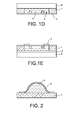
- a substrate 6 is then secured to the other main face of the frame 1, it will close the cavity 5 to prevent the fluid 4 from escaping ( figure 1D ).
- the last figure 1E shows the membrane equipped with actuating means 7 to move it to drive the fluid 4 towards the central part of the cavity 5.
- a disadvantage of the process described in these documents is that it is only suitable for sufficiently thick membranes, typically with a thickness greater than 50 microns for a polydimethylsiloxane membrane. Thinner membranes, very flexible or very large are too fragile to be carried on the frame. The applications listed more high require membranes of very small thickness, less than a few tens of micrometers, and sufficiently flexible to be able to deform significantly when operating the actuating means.
- the actuating means can be found only on the face of the membrane opposite the fluid otherwise, during the transfer of the membrane the risk of deformation and damage to the membrane are important.
- Another disadvantage of this method is that it is practiced at low pressure, of the order of 4.10 -2 HPa, which excludes the use as a fluid, a gas and most liquids that will evaporate during the deposit CVD.
- Another technique described for example in the patent application FR 2 919 073 is to deposit a sacrificial material in a cavity which is equipped with a support, to deposit the membrane on the sacrificial material by overflowing on the support so as to anchor thereon, to eliminate the sacrificial material by a hole drilled in the support and replace it with the fluid, then to plug the hole of the support.
- the disadvantage of this technique is due to sacrificial material. Indeed, it is difficult to eliminate, it takes a lot of time, several dozen hours, and we are never sure that everything has been eliminated. If sacrificial material remains, it may disrupt the operation of actuating means that would be bathed by the fluid or pollute the fluid.
- the object of the present invention is precisely to propose a process for producing a membrane device trapping a fluid that does not have the limitations and difficulties mentioned above.
- the method according to the invention makes it possible to use a wide range of fluids and materials for the membrane.
- Another object of the invention is to provide a membrane device trapping a fluid in which the deformation of the membrane at rest can be provided in advance, this deformation may be zero.
- Yet another object of the invention is to provide a membrane device trapping a fluid in which the membrane can be equipped with at least one instrument such as actuating means or a sensor disposed on the side of the fluid.
- a further object of the invention is to provide a membrane device trapping a fluid without having to resort to the use of a sacrificial material that could cause problems when using the membrane device if it does not. has not been properly eliminated.
- the fluid may be deposited on one of the substrates or distributed over the two substrates before the two substrates are assembled.
- the fluid can be introduced into the cavity once the two substrates are assembled.
- the introduction can be done through at least one through hole in one of the substrates and / or in a wall.
- the buffer layer can be removed to release the membrane at least in its central portion.
- the instrument is preferably in contact with the fluid.
- the formation of the walls on one of the substrates may be done by depositing a cord material, this material may be adhesive, and / or by etching the substrate and / or by depositing a modeling layer on the substrate, then etching the modeling layer and / or using a preformed modeling layer.
- the membrane may be deposited by chemical vapor deposition if it is inorganic or parylene, or by spin coating or by plating a film if it is organic.
- the assembly of the two substrates can be done by gluing.
- the fluid can be deposited or introduced by a so-called dispensing technique or by projection.
- the fluid can be in the form of liquid, gas or gel.
- FIGS. 3A to 3E A first example of the method which is the subject of the invention will now be described with reference to the FIGS. 3A to 3E .
- the substrates 110, 120 may be of mineral material such as glass, quartz, sapphire, silicon or other semiconductor material, a metal. Alternatively, they may be made of organic material such as polyethylene terephthalate PET, polyethylene naphthalate PEN, polymethyl methacrylate PMMA, polycarbonate PC. If the application of the device obtained by the process according to the invention is a liquid lens with a variable focal length, one of the substrates remaining at the end of the process for trapping the fluid will be chosen to be transparent to the optical radiation that has to pass through the lens.
- a membrane 111 is placed on one of the substrates, in this case, on the first substrate 110.
- the membrane 111 covers one of the main faces of the first substrate 110, it has a free face 111.1 and a face 111.2. contact with the first substrate 110.
- the membrane 111 may be made of organic materials such as polydimethylsiloxane, polymethyl methacrylate, polyethylene terephthalate, polycarbonate, parylene, epoxy or silicone resins, photosensitive resins, or mineral materials such as silicon, silicon oxide, silicon nitride, silicon carbide, polycrystalline silicon, titanium nitride, diamond carbon, tin and indium oxide, aluminum, copper, nickel.
- organic materials such as polydimethylsiloxane, polymethyl methacrylate, polyethylene terephthalate, polycarbonate, parylene, epoxy or silicone resins, photosensitive resins, or mineral materials such as silicon, silicon oxide, silicon nitride, silicon carbide, polycrystalline silicon, titanium nitride, diamond carbon, tin and indium oxide, aluminum, copper, nickel.
- the membrane will be transparent to the optical radiation to pass through it and in the mirror application, it will be reflective to the incident optical radiation.
- the membrane 111 may be deposited on the first substrate by CVD chemical vapor deposition, in particular if it is mineral or in parylene or by spin coating for other organic materials. Another way is to use for the membrane 111 an organic film, for example roll or plate that is just pressed on the first substrate.
- photosensitive resins allows once the membrane has been deposited from the engrave with a simple step of lithography to delimit its outline.
- An instrument is an object manufactured for a particular purpose.
- This instrument can be in whole or in part a means for actuating the membrane, a sensor, such as an environmental sensor capable of detecting for example the humidity, the pressure, the temperature, the nature of the residual gases, or such as a sensor.
- movement such as a gyroscope, an accelerometer, a magnetometer, or other.
- the instrument 112.1 is shown as one of the electrodes of an electrostatic actuator with at least one pair of electrodes placed opposite. It is made on the free face 111.1 of the membrane 111. It will be seen that the second substrate 120 will be equipped with the other electrode of the pair.
- the instrument 112.1 may be, in the case where it is a means for actuating the membrane, an electrically conductive electrode as just described, an element made of piezoelectric material, of magnetic material, electroactive polymer that deforms under the effect of an electric current.
- At least one wall 113 is formed on at least one of the substrates 110, 120, this wall 113 contributing to laterally delimiting a cavity 114 for receiving a fluid.
- the membrane 111 serves also to trap the fluid in the cavity 114 ( figure 3B ).
- the wall 114 is made on the second substrate 120.
- the second substrate 120 will then serve as a bottom 115 to the cavity 114. It is understood that one could make a wall on the first substrate, on the side of the membrane or on both substrates, in this case, the walls of the two substrates must cooperate to define the cavity.
- the wall 113 is made by etching a bowl 116 in the central portion of the second substrate 120, the edges of the bowl forming the wall 113 and the bottom of the bowl 116 forming the bottom 115 of the cavity.
- the etching can be done by reactive ion etching, by physical plasma etching, for example xenon difluoride XeF 2 or sulfur hexafluoride SF 6 , by wet chemical etching with, for example, TMAH or potassium hydroxide KOH.
- a bead of suitable material on the second substrate.
- a negative bonding resin such as benzocyclobutene BCB or SiNR polymer siloxane can be used to form the bead.
- the cord allows both to define the cavity and to seal the first and the second substrate.
- Other glues may be envisaged such as glues thermosetting or curing glues under the effect of ultraviolet.
- a deposition step on the second substrate of a mineral material such as silicon oxide or silicon nitride, a step of lithography and etching of the deposited material.
- the bottom 115 of the bowl 116 is equipped with another instrument 112.2 which, in this example, is another electrode to cooperate and form a pair with the electrode 112.1 carried by the membrane 111 (FIG. figure 3B ).
- the bowl is filled with fluid 117 ( figure 3C ). It is understood that this step could take place later.
- the fluid 117 may be a gas, a liquid or a gel.
- an incompressible fluid will preferably be chosen, it will therefore be a liquid or a gel. This gives better performance during actuation. It is of course possible that the fluid is compressible and a gas can then be used.
- the filling of the bowl 116 can be done using a syringe or the like, that is to say by a so-called dispensing technique or by projection from a nozzle.
- the assembly is placed at the time of assembly in an enclosure containing the gas at a desired pressure and having a desired composition.
- the volume of fluid placed in the bowl 116 must be adapted to the volume that will have the cavity once closed. It may be desired that the membrane 111 is slightly curved or that it is flat at rest.
- the bottom 115 of the bowl 116 must have a wettability such that the liquid or the gel spread as well as possible on the bottom 115, so that the entire volume of the cavity 114 can be easily filled.
- the fluid may be a gas such as, for example, air, nitrogen, helium, a liquid such as propylene carbonate, water, a liquid index, an optical oil, an ionic liquid, a gel such as an elastomer, for example polydimethylsiloxane PDMS.
- a gas such as, for example, air, nitrogen, helium
- a liquid such as propylene carbonate
- water a liquid index
- an optical oil such as an ionic liquid
- a gel such as an elastomer, for example polydimethylsiloxane PDMS.
- the fluid 117 is a liquid or a gel
- the fluid could be deposited on the first substrate 110, on the membrane side 111, or the fluid 117 deposited on both the first substrate 110 and the second substrate 120.
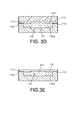
- the first substrate 110 and the second substrate 120 are then assembled by superimposing them and placing the membrane opposite the bowl, so as to perfect the cavity and trap the fluid 117 (FIG. 3D figure ).
- This assembly can be done by gluing, choosing an adhesive 118 and a bonding mode compatible with the fluid 117 to be trapped.
- the temperature and pressure conditions must avoid evaporation of the fluid 117.
- An ultraviolet activated bonding can be envisaged for fluids 117 evaporating at ambient temperature. This obviously assumes that one of the substrates 110, 120, at least, is transparent to ultraviolet. Some thermal collages can be done from 80 ° C. The bonding can be done in an enclosure in which the atmosphere, the pressure and the temperature are controlled so that the fluid does not evaporate.
- the first substrate 110 is eliminated in its entirety. This total elimination is suitable if the membrane 111 is sealingly attached to the wall 113 of the cavity 114. If there are risks of delamination, it is preferable to eliminate the first substrate only in its central part. The membrane is at least partly held by the fluid during its release.
- the removal of the first substrate 110 can be done for example by reactive ion etching (RIE reactive ion etching) and preferably by deep reactive ion etching (DRIE deep reactive ion etching). What distinguishes the two methods is the engraving depth. The typical depths of the RIE engravings are limited to a few micrometers and the etch rates are up to about one micrometer per minute. Gravure DRIE engraves much deeper patterns, up to about 600 micrometers or more, at speeds of the order of twenty micrometers per minute. The DRIE engraving is therefore well suited for this application.
- RIE reactive ion etching reactive ion etching
- DRIE deep reactive ion etching deep reactive ion etching
- the first substrate 110 is silicon, it is also possible to perform a physical plasma etching, for example of XeF 2 or SF 6, or a wet chemical etching with, for example, tetramethylammonium hydroxide TMAH or sodium hydroxide. potassium KOH.
- a physical plasma etching for example of XeF 2 or SF 6, or a wet chemical etching with, for example, tetramethylammonium hydroxide TMAH or sodium hydroxide. potassium KOH.
- FIGS. 4A to 4E another example of the method according to the invention will be described.
- a first substrate 110 and a second substrate 120 we now we place a membrane 111.1, 111.2 on each of the substrates 110, 120 ( Figure 4A ).
- a cup 116.1, 116.2 is formed on each of the substrates 110, 120 delimited by one or more walls 113.1, 113.2 (FIG. Figure 4B ).
- the walls 113.1, 113.2 of the Figure 4B contribute to laterally defining a cavity, they are located above the substrates 110, 120.
- the walls 113.1, 113.2 may be formed by a bead of adhesive, for example, negative bonding resin such as for example the resin based on benzocyclobutene BCB or siloxane polymer (SiNR).
- adhesive for example, negative bonding resin such as for example the resin based on benzocyclobutene BCB or siloxane polymer (SiNR).
- SiNR siloxane polymer
- the two glue beads 113.1, 113.2 do not necessarily have the same height, they can have constant or different heights depending on the location. They are complementary in terms of thickness, the cavity 114 once completed having a substantially constant wall 114.
- the cords 113.1, 113.2 may be discontinuous or not and complementary in terms of extent on the substrates 110, 120, which means that one will extend over at least a first portion of the perimeter of the cavity and the other on at least a second portion of the perimeter of the cavity, the two parts covering the entire perimeter of the completed cavity.
- thermosetting glues or photocurable UV.
- glues can be deposited on the substrates by screen printing or by dispensing.
- Non-adhesive cords 113.1, 113.2 of non-adhesive material could of course be used.
- the non-adhesive cords are generally made of polymerized materials such as benzocyclobutene BCB or SU8 resin unlike adhesive cords. It is also possible to produce the non-adhesive beads, as described above, by deposition, lithography and etching steps of inorganic materials such as silicon oxide or silicon nitride.
- one bead could be adhesive and not the other, if at least two cords are provided.
- each bowl 116.1, 116.2 has a bottom 115.1, 115.2 formed by the membrane and not directly the substrate as in the previous example.
- the two substrates 110, 120 are then assembled together by stacking them.
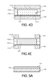
- Cuvettes 116.1, 116.2 are arranged face to face so as to trap fluid 117 between the two membranes 111.1, 111.2 (FIG. figure 4D ). If at least one of the cords 113.1, 113.2 used to delimit the cavity is adhesive, this assembly is done without problem. If none of the cords is adhesive, place glue on at least one of the cords. This assembly can be done with fluid as a liquid because the volumes are low and surface voltages are sufficient.
- the two substrates 110, 120 can then be completely or partially removed, to release the two membranes 111.1, 111.2 at least in their central part.
- the bottom 115 of the bowl 116 should allow to spread the fluid as much as possible 117.
- the bottom is made by the membranes. This condition is still desirable in the second example, but, moreover, insofar as the walls delimiting the cavity are generally not in the same material as the bottoms, it is preferable for each substrate that the wall is made in a material having a lower wettability than the bottom so as to avoid a fluid overflow.
- this stress preferably being a tension to prevent any buckling phenomenon at rest, it is recommended to insert a buffer layer 119 between the first substrate 110 and the 111.
- This buffer layer has the desired state of stress for the membrane.
- the membrane stress can be determined by simulation from parameters related to the membrane, to the buffer layer and possibly to at least one other layer that would be present, these parameters being, for example, their initial stress state, their Young's modulus. , their thickness. Once released, the membrane will not have the same constraint as the buffer layer. The stress of the released membrane depends on the parameters mentioned above.
- This buffer layer 119 may be made of silicon oxide or silicon nitride, for example. It can be carried out by plasma-activated vapor deposition PECVD. The buffer layer 119 could have been used in the two previous embodiments.
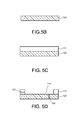
- the second substrate 120 will serve as a basis for modeling the cavity ( Figure 5B ).
- a layer 121 intended to be shaped to form the wall 113 of the cavity ( Figure 5C ).
- a drawn layer for example made of polyethylene terephthalate PET, of polyethylene naphthalate PEN, of polymethyl methacrylate PMMA, of polycarbonate PC.
- the modeling layer may be obtained by depositing a mineral material, such as silicon oxide or silicon nitride, and lithography and etching operations.
- a mineral material such as silicon oxide or silicon nitride
- the modeling layer 121 is kept only at what will become the wall 113 of the cavity 114 ( figure 5D ).
- FIG. 5E the assembly of the two substrates 110, 120 has been illustrated in order to finalize the cavity 114.
- the membrane 111 is bonded to the wall 113 of the cavity 114.
- An adhesive seal 124 has been inserted between the membrane and the top part. of the wall 113 of the cavity 114.
- At least one through hole 122 is pierced in the second substrate and the fluid 117 is injected via this through hole 121.
- the through hole 122 opens out at the bottom 115 of the cavity 114.
- the through hole 117 is then plugged, the plug carrying reference 123 ( figure 5F ).
- the through holes 122 were drilled before assembling the two substrates.
- the drilling can be DRIE or wet etching.
- Other methods that are also suitable for other types of substrate are laser drilling, machining, sanding, for example.
- the figure 5G shows the first substrate 110 which has been completely removed and the buffer layer 119 only partially. It remains at the wall of the cavity. She could have been eliminated totally.
- the membrane 111 has a central portion which is released.
- the buffer layer 119 may have a temporary membership property. In this case, it is totally removed. It is also possible to introduce, if the buffer layer does not have this temporary adhesion property, an additional layer between the buffer layer and the substrate, having this temporary adhesion property.
- the buffer layer may also serve to control the stress in the membrane and / or as just described to remove the substrate when it has this temporary adhesion property.
- the temporary adhesion can be obtained for example with a material whose adhesion decreases when the temperature is increased.
- a material whose adhesion decreases when the temperature is increased For example, for the buffer layer that has this temporary adhesion property or for the additional layer of Brewer Science HT 1010-type glue. If there is the additional layer, the buffer layer may be of another material.
- the buffer layer is made of silicon oxide or silicon nitride, for example, it can also be removed by reactive ion etching or by wet chemical etching with, for example, hydrofluoric acid for the oxide of silicon or silicon dioxide. orthophosphoric acid for silicon nitride.
- the process according to the invention makes it possible to widen the range of materials that can be used for the membrane, especially for thin layers, less than about 50 micrometers, or even less than 10 micrometers and for example between 1 and 5 micrometers.
- the method of the invention makes it possible, by releasing the membrane after assembly of the two substrates and filling the cavity with the fluid, to offer the membrane, during its release, a mechanical hold by the fluid trapped in the cavity.
- the release of the membrane after encapsulation allows the fluid which is trapped and in contact with it to participate in its maintenance and possibly influence its deformation.
- the membrane may have a thickness of less than 10 micrometers for diameters greater than one millimeter.
- Such a membrane may have a weak Young's modulus, for example less than 10 GPa. It is then possible to use for the realization of fine organic materials. Such materials could not be used if the membrane was released before filling.
- the flexibility of the membrane can be characterized by deformation during an actuation greater than its thickness, which corresponds to a mechanical regime of large deformations.
- the release of the membrane after filling is much easier than the release before filling.
- strong constraints are generated on the handling of the substrates because of the fragility of the membrane and on the choice of processes to use.
- a deep reactive ion etching method can not be used because of the pressure difference between the suction of the substrate holder and the vacuum of the chamber. This difference in pressure could cause a rupture of the membrane.
- the method which is the subject of the invention also makes it possible to better control the deformation of the membrane at rest, especially as the fluid is incompressible.
- the presence of an incompressible fluid that is to say a liquid or an incompressible gel, is advantageous compared to configurations with a compressible fluid because the membrane can rely on the incompressible fluid without suffering the effects of differences in pressure between the two faces of the membrane.
- This makes it possible to prevent diaphragm bursting due to the force exerted by the fluid when the device is evacuated, during the step of removing the substrate by reactive ion etching, or to have membrane bonding effects on the membrane. bottom of the cavity if the pressure in the cavity is too low at the end of the process.
Landscapes
- Physics & Mathematics (AREA)
- General Physics & Mathematics (AREA)
- Optics & Photonics (AREA)
- Engineering & Computer Science (AREA)
- Mechanical Engineering (AREA)
- General Engineering & Computer Science (AREA)
- Micromachines (AREA)
- Separation Using Semi-Permeable Membranes (AREA)
Abstract
Description
La présente invention concerne la fabrication de dispositifs à membrane emprisonnant un fluide.The present invention relates to the manufacture of membrane devices trapping a fluid.
Dans la majorité des applications le fluide sera incompressible. Un fluide est dit incompressible lorsque son volume demeure quasiment constant sous l'action d'une pression externe. Dans ce contexte le fluide peut être un liquide ou un gel, les gaz n'étant pas incompressibles.In most applications the fluid will be incompressible. A fluid is said to be incompressible when its volume remains almost constant under the action of an external pressure. In this context the fluid may be a liquid or a gel, the gases not being incompressible.
Un tel dispositif à membrane emprisonnant un fluide incompressible peut servir par exemple de lentille à distance focale ajustable, de miroir à courbure ajustable ou de micro pompe.Such a membrane device trapping an incompressible fluid can serve for example adjustable focal length lens, adjustable curvature mirror or micro pump.
L'invention peut bien sûr s'appliquer à d'autres dispositifs nécessitant de placer une membrane sur une cavité contenant un fluide qu'il soit incompressible ou non.The invention can of course be applied to other devices requiring to place a membrane on a cavity containing a fluid whether it is incompressible or not.
Deux types de techniques sont généralement utilisés pour emprisonner un fluide sous une membrane. On va décrire un premier procédé qui se base sur l'enseignement du document [1] dont les références se trouvent en fin de description. On part d'un cadre 1 possédant une ou plusieurs ouvertures traversantes 2 (
Le document [2] dont les références se trouvent en fin de description montre également une membrane directement reportée sur un cadre rigide ajouré assemblé à un substrat transparent.The document [2] whose references are at the end of the description also shows a membrane directly transferred to a rigid openwork frame assembled to a transparent substrate.
Un inconvénient du procédé décrit dans ces documents est qu'il ne convient que pour des membranes suffisamment épaisses, typiquement d'épaisseur supérieure à 50 micromètres pour une membrane en polydiméthylsiloxane. Des membranes plus fines, très souples ou très grandes sont trop fragiles pour être reportées sur le cadre. Les applications listées plus haut requièrent des membranes d'épaisseur très petites, inférieures à quelques dizaines de micromètres, et suffisamment souples pour pouvoir se déformer de manière significative lorsque l'on actionne les moyens d'actionnement.A disadvantage of the process described in these documents is that it is only suitable for sufficiently thick membranes, typically with a thickness greater than 50 microns for a polydimethylsiloxane membrane. Thinner membranes, very flexible or very large are too fragile to be carried on the frame. The applications listed more high require membranes of very small thickness, less than a few tens of micrometers, and sufficiently flexible to be able to deform significantly when operating the actuating means.
De plus, les moyens d'actionnement ne peuvent se trouver que sur la face de la membrane opposée au fluide sinon, lors du report de la membrane les risques de déformation et d'endommagement de la membrane sont importants. Dans le cadre d'une lentille liquide à actionnement électrostatique, il est bien préférable de positionner les électrodes d'une paire d'électrodes formant les moyens d'actionnement en contact avec le fluide pour optimiser les forces engendrées.In addition, the actuating means can be found only on the face of the membrane opposite the fluid otherwise, during the transfer of the membrane the risk of deformation and damage to the membrane are important. In the context of an electrostatically actuated liquid lens, it is preferable to position the electrodes of a pair of electrodes forming the actuating means in contact with the fluid to optimize the generated forces.
Encore un autre inconvénient est que la déformée de la membrane au repos dépend fortement d'une part du cordon de colle utilisé pour solidariser la membrane au cadre et d'autre part, de la quantité de fluide emprisonné. La prévision de cette déformée au repos est extrêmement difficile et en particulier, il est quasiment impossible d'obtenir une membrane plane ou quasi-plane au repos.Yet another disadvantage is that the deformation of the membrane at rest strongly depends on a part of the bead of adhesive used to secure the membrane to the frame and secondly, the amount of trapped fluid. The prediction of this deformed at rest is extremely difficult and in particular, it is almost impossible to obtain a flat or quasi-flat membrane at rest.
Un autre procédé connu, se basant sur l'enseignement du document [3] dont les références se trouvent en fin de description, va être décrit ci-dessous. On part d'un substrat 7 qui délimite au moins une cavité ou qui peut être plan comme illustré sur la
Un autre inconvénient de ce procédé est qu'il se pratique à basse pression, de l'ordre de 4.10-2 HPa, ce qui exclut d'utiliser comme fluide, un gaz et la plupart des liquides qui vont s'évaporer lors du dépôt CVD.Another disadvantage of this method is that it is practiced at low pressure, of the order of 4.10 -2 HPa, which excludes the use as a fluid, a gas and most liquids that will evaporate during the deposit CVD.
Comme la technique décrite précédemment, il n'est pas possible de fonctionnaliser la membrane avec des moyens d'actionnement situés côté liquide.Like the technique described above, it is not possible to functionalize the membrane with actuating means located on the liquid side.
Avec cette technique également, il est difficile de maîtriser la déformée de la membrane au repos, cette déformée dépend de la forme de la goutte de liquide déposée sur le substrat ainsi que de son comportement sous vide au cours du dépôt.With this technique also, it is difficult to control the deformation of the membrane at rest, this deformed depends on the shape of the drop of liquid deposited on the substrate and its vacuum behavior during deposition.
Une autre technique, décrite par exemple dans la demande de brevet
La présente invention a justement comme but de proposer un procédé de réalisation d'un dispositif à membrane emprisonnant un fluide qui ne présente pas les limitations et difficultés mentionnées ci-dessus.The object of the present invention is precisely to propose a process for producing a membrane device trapping a fluid that does not have the limitations and difficulties mentioned above.
En particulier, le procédé selon l'invention permet d'utiliser une grande gamme de fluides et de matériaux pour la membrane.In particular, the method according to the invention makes it possible to use a wide range of fluids and materials for the membrane.
Un autre but de l'invention est de réaliser un dispositif à membrane emprisonnant un fluide dans lequel la déformée de la membrane au repos peut être prévue à l'avance, cette déformée pouvant être nulle.Another object of the invention is to provide a membrane device trapping a fluid in which the deformation of the membrane at rest can be provided in advance, this deformation may be zero.
Encore un autre but de l'invention est de réaliser un dispositif à membrane emprisonnant un fluide dans lequel la membrane peut être équipée d'au moins un instrument tel des moyens d'actionnement ou un capteur disposé du côté du fluide.Yet another object of the invention is to provide a membrane device trapping a fluid in which the membrane can be equipped with at least one instrument such as actuating means or a sensor disposed on the side of the fluid.
Un but supplémentaire de l'invention est de réaliser un dispositif à membrane emprisonnant un fluide sans à avoir à recourir à l'utilisation d'un matériau sacrificiel qui pourrait poser des problèmes lors de l'utilisation du dispositif à membrane s'il n'a pas été correctement éliminé.A further object of the invention is to provide a membrane device trapping a fluid without having to resort to the use of a sacrificial material that could cause problems when using the membrane device if it does not. has not been properly eliminated.
Pour atteindre ces buts, l'invention concerne plus précisément un procédé de réalisation d'un dispositif à membrane contribuant à emprisonner un fluide contenu dans une cavité dans lequel :
- on fournit deux substrats,
- on dispose une membrane sur l'un et/ou sur l'autre des substrats,
- on forme une ou plusieurs parois contribuant à délimiter latéralement la cavité, ces parois étant situées sur ou dans l'un des substrats et/ou sur ou dans l'autre des substrats, cette cavité étant destinée à contenir le fluide,
- on assemble les deux substrats l'un à l'autre en les superposant de manière à parfaire la cavité, la membrane ou chaque membrane contribuant également à délimiter la cavité,
- on emprisonne du fluide dans la cavité entre les substrats, la membrane ou chaque membrane étant baignée par le fluide,
- on ôte au moins une partie de l'un des substrats et/ou de l'autre des substrats dans la mesure où l'un et/ou l'autre des substrats sont équipés d'une membrane pour libérer la membrane au moins dans sa partie centrale, la membrane étant au moins en partie maintenue par le fluide lors de sa libération.
- two substrates are provided,
- we have a membrane on one and / or the other of the substrates,
- forming one or more walls contributing to delimit laterally the cavity, these walls being located on or in one of the substrates and / or on or in the other of the substrates, this cavity being intended to contain the fluid,
- the two substrates are assembled together by superimposing them so as to perfect the cavity, the membrane or each membrane also contributing to delimiting the cavity,
- fluid is trapped in the cavity between the substrates, the membrane or each membrane being bathed by the fluid,
- at least a portion of one of the substrates and / or the other of the substrates is removed insofar as one and / or the other of the substrates is equipped with a membrane to release the membrane at least in its central part, the membrane being at least partly held by the fluid during its release.
L'expression « ces parois étant situées sur l'un des substrats et/ou sur l'autre des substrats » signifie par-dessus le substrat concerné.The expression "these walls being located on one of the substrates and / or on the other of the substrates" means above the relevant substrate.
Le fluide peut être déposé sur l'un des substrats ou réparti sur les deux substrats avant l'assemblage des deux substrats.The fluid may be deposited on one of the substrates or distributed over the two substrates before the two substrates are assembled.
En variante, le fluide peut être introduit dans la cavité une fois que les deux substrats sont assemblés.Alternatively, the fluid can be introduced into the cavity once the two substrates are assembled.
L'introduction peut se faire par l'intermédiaire d'au moins un trou traversant dans un des substrats et/ou dans une paroi.The introduction can be done through at least one through hole in one of the substrates and / or in a wall.
Pour maîtriser l'état de contrainte de la membrane ou de chaque membrane une fois libérée, on peut insérer une couche tampon entre l'un des substrats et la membrane et/ou entre l'autre des substrats et la membrane, cette couche tampon ayant une contrainte en tension voulue de manière à ce que la membrane ait une contrainte en tension déterminée lors de sa libération.To control the state of stress of the membrane or of each membrane once released, it is possible to insert a buffer layer between one of the substrates and the membrane and / or between the other substrates and the membrane, this buffer layer having a desired voltage stress so that the membrane has a voltage stress determined during its release.
On peut éliminer la couche tampon pour libérer la membrane au moins dans sa partie centrale.The buffer layer can be removed to release the membrane at least in its central portion.
On peut équiper la membrane et/ou l'un des substrats d'au moins un instrument tel des moyens d'actionnement, un capteur.One can equip the membrane and / or one of the substrates of at least one instrument such as actuating means, a sensor.
L'instrument est de préférence en contact avec le fluide.The instrument is preferably in contact with the fluid.
La formation des parois sur l'un des substrats peut se faire par dépôt d'un matériau en cordon, ce matériau pouvant être adhésif, et/ou par gravure du substrat et/ou par dépôt d'une couche de modelage sur le substrat, puis gravure de la couche de modelage et/ou par utilisation d'une couche de modelage préformée.The formation of the walls on one of the substrates may be done by depositing a cord material, this material may be adhesive, and / or by etching the substrate and / or by depositing a modeling layer on the substrate, then etching the modeling layer and / or using a preformed modeling layer.
La membrane peut être déposée par dépôt chimique en phase vapeur si elle est minérale ou en parylène, ou bien par dépôt à la tournette ou encore par placage d'un film si elle est organique.The membrane may be deposited by chemical vapor deposition if it is inorganic or parylene, or by spin coating or by plating a film if it is organic.
L'assemblage des deux substrats peut se faire par collage.The assembly of the two substrates can be done by gluing.
Le fluide peut être déposé ou introduit par une technique dite de dispense ou bien par projection.The fluid can be deposited or introduced by a so-called dispensing technique or by projection.
Le fluide peut être aussi bien sous forme de liquide, de gaz ou de gel.The fluid can be in the form of liquid, gas or gel.
La présente invention sera mieux comprise à la lecture de la description d'exemples de réalisation donnés, à titre purement indicatif et nullement limitatif, en faisant référence aux dessins annexés sur lesquels:
- les
figures 1A à 1E , déjà décrites, montrent différentes étapes d'un procédé de l'art antérieur pour la réalisation d'un dispositif à membrane contribuant à emprisonner un fluide; - la
figure 2 , déjà décrite, montre en coupe un dispositif à membrane contribuant à emprisonner un fluide obtenu par un procédé de l'art antérieur ; - les
figures 3A à 3E , montrent différentes étapes d'un exemple de procédé de réalisation d'un dispositif à membrane contribuant à emprisonner un fluide selon l'invention ; - les
figures 4A à 4E , montrent différentes étapes d'un autre exemple de procédé de réalisation d'un dispositif à membrane contribuant à emprisonner un fluide selon l'invention ; - les
figures 5A à 5G , montrent différentes étapes d'un troisième exemple de procédé de réalisation d'un dispositif à membrane contribuant à emprisonner un fluide selon l'invention.
- the
FIGS. 1A to 1E , already described, show different steps of a method of the prior art for producing a membrane device contributing to trapping a fluid; - the
figure 2 , already described, shows in section a membrane device contributing to trapping a fluid obtained by a method of the prior art; - the
FIGS. 3A to 3E show different steps of an exemplary method of producing a membrane device contributing to trapping a fluid according to the invention; - the
FIGS. 4A to 4E show different steps of another example of a method of producing a membrane device contributing to trapping a fluid according to the invention; - the
Figures 5A to 5G , show different steps of a third exemplary embodiment method a membrane device contributing to trapping a fluid according to the invention.
Des parties identiques, similaires ou équivalentes des différentes figures portent les mêmes références numériques de façon à faciliter le passage d'une figure à l'autre.Identical, similar or equivalent parts of the different figures bear the same numerical references so as to facilitate the passage from one figure to another.
Les différentes parties représentées sur les figures ne le sont pas nécessairement selon une échelle uniforme, pour rendre les figures plus lisibles.The different parts shown in the figures are not necessarily in a uniform scale, to make the figures more readable.
On va maintenant décrire un premier exemple du procédé objet de l'invention en se référant aux
On part d'un premier substrat 110 (
On place une membrane 111 sur l'un des substrats, en l'occurrence, dans cet exemple sur le premier substrat 110. La membrane 111 recouvre une des faces principales du premier substrat 110, elle possède une face libre 111.1 et une face 111.2 en contact avec le premier substrat 110. En variante, on pourrait placer une membrane sur chacun des substrats comme on le verra plus loin.A
La membrane 111 pourra être réalisée être réalisée à base de matériaux organiques tels que le polydiméthylsiloxane, le polyméthacrylate de méthyle, le polyéthylène téréphtalate, le polycarbonate, le parylène, les résines époxydes ou silicones, les résines photosensibles, ou de matériaux minéraux tels que le silicium, l'oxyde de silicium, le nitrure de silicium, le carbure de silicium, le silicium polycristallin, le nitrure de titane, le carbone diamant, l'oxyde d'étain et d'indium, l'aluminium, le cuivre, le nickel. Dans l'application lentille liquide, la membrane sera transparente au rayonnement optique devant la traverser et dans l'application miroir, elle sera réfléchissante au rayonnement optique incident.The
La membrane 111 peut être déposée sur le premier substrat par dépôt chimique en phase vapeur CVD notamment si elle est minérale ou en parylène ou bien par dépôt à la tournette pour d'autres matériaux organiques. Un autre moyen est d'utiliser pour la membrane 111 un film organique, par exemple en rouleau ou en plaque que l'on vient plaquer sur le premier substrat. L'utilisation de résines photosensibles permet une fois que la membrane a été déposée de la graver avec une simple étape de lithographie pour délimiter son contour.The
On peut équiper la membrane 111 d'au moins un instrument 112.1. Par instrument, on entend un objet fabriqué en vue d'une utilisation particulière. Cet instrument peut être en totalité ou en partie un moyen d'actionnement de la membrane, un capteur, tel un capteur environnemental apte à détecter par exemple l'humidité, la pression, la température, la nature des gaz résiduels ou tel un capteur de mouvement comme par exemple un gyroscope, un accéléromètre, un magnétomètre, ou autre.It is possible to equip the
Dans l'exemple de la
L'instrument 112.1 peut être, dans le cas où il s'agit d'un moyen d'actionnement de la membrane, une électrode conductrice de l'électricité comme on vient de le décrire, un élément en matériau piézoélectrique, en matériau magnétique, en polymère électroactif qui se déforme sous l'effet d'un courant électrique.The instrument 112.1 may be, in the case where it is a means for actuating the membrane, an electrically conductive electrode as just described, an element made of piezoelectric material, of magnetic material, electroactive polymer that deforms under the effect of an electric current.
On forme au moins une paroi 113 sur au moins un des substrats 110, 120, cette paroi 113 contribuant à délimiter latéralement une cavité 114 devant accueillir un fluide. La membrane 111 sert également à emprisonner le fluide dans la cavité 114 (
Dans l'exemple des
Dans cet exemple des
Si le second substrat 120 est en silicium, la gravure peut se faire par gravure ionique réactive, par gravure physique au plasma par exemple de difluorure de xénon XeF2 ou d'hexafluorure de soufre SF6, par gravure chimique humide avec par exemple de l'hydroxyde de tétraméthylammonium TMAH ou de l'hydroxyde de potassium KOH.If the
Il est bien entendu que l'on pourrait procéder autrement pour réaliser la paroi de la cavité, par exemple en déposant un cordon de matériau approprié sur le second substrat. On peut utiliser pour former le cordon, une résine de collage négative telle que du benzocyclobutène BCB ou du siloxane polymère SiNR. Le cordon permet à la fois de définir la cavité et de sceller le premier et le second substrat. D'autres colles peuvent être envisagées telles que les colles thermodurcissables ou les colles durcissant sous l'effet des ultraviolets.It is understood that one could proceed otherwise to achieve the wall of the cavity, for example by depositing a bead of suitable material on the second substrate. A negative bonding resin such as benzocyclobutene BCB or SiNR polymer siloxane can be used to form the bead. The cord allows both to define the cavity and to seal the first and the second substrate. Other glues may be envisaged such as glues thermosetting or curing glues under the effect of ultraviolet.
On peut également réaliser un cordon en effectuant une étape dépôt sur le second substrat d'un matériau minéral tel que l'oxyde de silicium ou le nitrure de silicium, une étape de lithographie et de gravure du matériau déposé.It is also possible to produce a bead by performing a deposition step on the second substrate of a mineral material such as silicon oxide or silicon nitride, a step of lithography and etching of the deposited material.
On équipe le fond 115 de la cuvette 116 d'un autre instrument 112.2 qui, dans cet exemple, est une autre électrode devant coopérer et former une paire avec l'électrode 112.1 portée par la membrane 111 (
On emplit la cuvette du fluide 117 (
Le remplissage de la cuvette 116 peut se faire à l'aide d'une seringue ou analogue c'est-à-dire par une technique dite de dispense ou bien par projection à partir d'une buse. Pour un fluide gazeux, l'ensemble est placé au moment de l'assemblage dans une enceinte contenant le gaz à une pression voulue et ayant une composition voulue.The filling of the bowl 116 can be done using a syringe or the like, that is to say by a so-called dispensing technique or by projection from a nozzle. For a gaseous fluid, the assembly is placed at the time of assembly in an enclosure containing the gas at a desired pressure and having a desired composition.
Le volume de fluide placé dans la cuvette 116 doit être adapté au volume qu'aura la cavité une fois fermée. On peut désirer que la membrane 111 soit légèrement bombée ou qu'elle soit plane au repos.The volume of fluid placed in the bowl 116 must be adapted to the volume that will have the cavity once closed. It may be desired that the
Le fond 115 de la cuvette 116 doit avoir une mouillabilité telle que le liquide ou le gel s'étalent le mieux possible sur le fond 115, pour que tout le volume de la cavité 114 puisse être aisément rempli.The
Le fluide peut être un gaz tel que par exemple, l'air, l'azote, l'hélium, un liquide tel que le carbonate de propylène, l'eau, un liquide d'indice, une huile optique, un liquide ionique, un gel tel qu'un élastomère par exemple du polydiméthylsiloxane PDMS.The fluid may be a gas such as, for example, air, nitrogen, helium, a liquid such as propylene carbonate, water, a liquid index, an optical oil, an ionic liquid, a gel such as an elastomer, for example polydimethylsiloxane PDMS.
En variante notamment si le fluide 117 est un liquide ou un gel, on pourrait déposer le fluide sur le premier substrat 110, côté membrane 111, ou déposer le fluide 117 à la fois sur le premier substrat 110 et sur le second substrat 120.As a variant, especially if the fluid 117 is a liquid or a gel, the fluid could be deposited on the
On assemble ensuite le premier substrat 110 et le second substrat 120 en les superposant et en plaçant la membrane en vis-à-vis de la cuvette, de manière à parfaire la cavité et emprisonner le fluide 117 (
Cet assemblage peut se faire par collage, en choisissant une colle 118 et un mode de collage compatibles avec le fluide 117 à emprisonner. En particulier, les conditions de température et de pression doivent éviter l'évaporation du fluide 117.This assembly can be done by gluing, choosing an adhesive 118 and a bonding mode compatible with the fluid 117 to be trapped. In particular, the temperature and pressure conditions must avoid evaporation of the
Un collage à activation par ultraviolets peut être envisagé pour des fluides 117 s'évaporant à température ambiante. Cela suppose bien évidemment que l'un des substrats 110, 120, au moins, est transparent aux ultraviolets. Certains collages thermiques peuvent se faire dès 80°C. Le collage peut se faire dans une enceinte dans laquelle on contrôle l'atmosphère, la pression et la température de manière à ce que fluide ne s'évapore pas.An ultraviolet activated bonding can be envisaged for
On peut ensuite éliminer le premier substrat 110 pour libérer la membrane 111. Dans l'exemple de la
L'élimination du premier substrat 110 peut se faire par exemple par gravure ionique réactive (RIE reactive ion etching) et de préférence par gravure ionique réactive profonde (DRIE deep reactive ion etching). Ce qui distingue les deux méthodes, c'est la profondeur de gravure. Les profondeurs typiques des gravures RIE sont limitées à quelques micromètres et les vitesses de gravure vont jusqu'à environ un micromètre par minute. La gravure DRIE grave des motifs beaucoup plus profonds, jusqu'à environ 600 micromètres voire plus, à des vitesses de l'ordre de la vingtaine de micromètres par minute. La gravure DRIE convient donc bien pour cette application.The removal of the
Si le premier substrat 110 est en silicium, il est également possible de faire une gravure physique au plasma par exemple de XeF2 ou de SF6 ou une gravure chimique humide avec par exemple de l'hydroxyde de tétraméthylammonium TMAH ou de l'hydroxyde de potassium KOH.If the
En se référant aux
On forme une cuvette 116.1, 116.2 sur chacun des substrats 110, 120, délimitée par une ou plusieurs parois 113.1, 113.2 (
Les deux cordons de colle 113.1, 113.2 n'ont pas forcement la même hauteur, ils peuvent avoir des hauteurs constantes ou différentes selon l'endroit. Ils sont complémentaires en termes d'épaisseur, la cavité 114 une fois achevée ayant une paroi sensiblement constante 114. Les cordons 113.1, 113.2 peuvent être discontinus ou non et complémentaires en termes d'étendue sur les substrats 110, 120, ce qui signifie que l'un va s'étendre sur au moins une première portion du périmètre de la cavité et l'autre sur au moins une seconde partie du périmètre de la cavité, les deux parties couvrant tout le périmètre de la cavité achevée.The two glue beads 113.1, 113.2 do not necessarily have the same height, they can have constant or different heights depending on the location. They are complementary in terms of thickness, the
D'autres types de colles peuvent bien sûr être employés comme par exemple des colles thermodurcissables ou photodurcissables aux UV.Other types of glue can of course be used such as for example thermosetting glues or photocurable UV.
Ces colles peuvent être déposées sur les substrats par sérigraphie ou par dispense.These glues can be deposited on the substrates by screen printing or by dispensing.
Des cordons 113.1, 113.2 en matériau non adhésif pourraient bien sûr être utilisés. Les cordons non adhésifs sont généralement réalisés en matériaux polymérisés tels que le benzocyclobutène BCB ou la résine SU8 contrairement aux cordons adhésifs. On peut aussi réaliser les cordons non adhésifs, comme on l'a décrit plus haut, par des étapes de dépôt, lithographie et gravure de matériaux minéraux tels que l'oxyde de silicium ou le nitrure de silicium.Cords 113.1, 113.2 of non-adhesive material could of course be used. The non-adhesive cords are generally made of polymerized materials such as benzocyclobutene BCB or SU8 resin unlike adhesive cords. It is also possible to produce the non-adhesive beads, as described above, by deposition, lithography and etching steps of inorganic materials such as silicon oxide or silicon nitride.
En variante, un cordon pourrait être adhésif et pas l'autre, si on prévoit au moins deux cordons.Alternatively, one bead could be adhesive and not the other, if at least two cords are provided.
On peut ensuite déposer, pour chacun des substrats 110, 120, dans l'espace délimité par le cordon de colle 113.1, 113.2, si celui-ci est continu, du fluide 117 (
Dans l'exemple décrit aux
On assemble ensuite les deux substrats 110, 120 l'un à l'autre en les empilant. Les cuvettes 116.1, 116.2 sont disposées face à face de manière à emprisonner le fluide 117 entre les deux membranes 111.1, 111.2 (
On peut ensuite éliminer les deux substrats 110, 120 totalement ou partiellement, pour libérer les deux membranes 111.1, 111.2 au moins dans leur partie centrale.The two
Sur la
Sur les
Dans le premier exemple du procédé de l'invention décrit aux
Lors de la description du premier exemple, on avait indiqué que le fond 115 de la cuvette 116 devait laisser s'étaler le plus possible le fluide 117. Dans le second exemple, le fond est réalisé par les membranes. Cette condition est toujours souhaitable dans le second exemple, mais, de plus, dans la mesure où les parois délimitant la cavité ne sont généralement pas dans le même matériau que les fonds, il est préférable, pour chaque substrat que la paroi soit réalisée dans un matériau ayant une mouillabilité inférieure à celle du fond de manière à éviter un débordement de fluide.In the description of the first example, it was stated that the
Sur les
Si on désire maîtriser l'état de contrainte de la membrane lors de sa libération, cette contrainte étant de préférence une tension pour éviter tout phénomène de flambage au repos, il est préconisé d'insérer une couche tampon 119 entre le premier substrat 110 et la membrane 111. C'est ce que la
Cette couche tampon 119 peut être réalisée en oxyde de silicium ou en nitrure de silicium par exemple. Elle peut être réalisée par dépôt en phase vapeur activé par plasma PECVD. La couche tampon 119 aurait pu être utilisée dans les deux modes de réalisation précédents.This
Le second substrat 120 va servir de base pour le modelage de la cavité (
Si on souhaite utiliser une couche à modeler préformée, on peut utiliser une couche emboutie par exemple en polyéthylène téréphtalate PET, en polyéthylène naphtalate PEN, en polyméthacrylate de méthyle PMMA, en polycarbonate PC.If it is desired to use a preformed modeling layer, it is possible to use a drawn layer, for example made of polyethylene terephthalate PET, of polyethylene naphthalate PEN, of polymethyl methacrylate PMMA, of polycarbonate PC.
En variante, la couche à modeler peut être obtenue par dépôt d'un matériau minéral, tel que de l'oxyde de silicium ou du nitrure de silicium et des opérations de lithographie et gravure. On ne conserve la couche à modeler 121 qu'au niveau de ce qui deviendra la paroi 113 de la cavité 114 (
Sur la
On perce au moins un trou traversant 122 dans le second substrat et on injecte via ce trou traversant 121 le fluide 117. Le trou traversant 122 débouche au niveau du fond 115 de la cavité 114. Le trou traversant 117 est ensuite bouché, le bouchon portant la référence 123 (
Ce mode de remplissage convient bien si le fluide est du gaz mais pas seulement. Bien sûr, le trou traversant ne doit pas attaquer de membrane. Il est possible de faire le trou traversant pour le remplissage, dans la paroi de la cavité et pas dans son fond, cela convient particulièrement si les deux substrats sont recouverts d'une membrane. Sur les
Dans l'exemple décrit, les trous traversants 122 ont été percés avant l'assemblage des deux substrats. Si le substrat est en silicium, le perçage peut se faire DRIE ou par gravure humide. D'autres méthodes convenant également pour d'autres types de substrat sont le perçage laser, l'usinage, le sablage par exemple.In the example described, the through
Il est possible de percer les trous traversants 122 après l'assemblage des deux substrats. Il faut juste éviter que des débris de substrat ou de paroi ne pénètrent dans la cavité et qu'ils y restent.It is possible to drill through
La
On aurait pu, bien sûr, conserver partiellement le substrat comme sur la
Il est préférable, notamment dans le cas où l'on désire ôter le substrat dans sa totalité, de choisir un matériau qui autorise un décollement de la couche tampon pour permettre le retrait du substrat.It is preferable, especially in the case where it is desired to remove the substrate in its entirety, to choose a material that allows delamination of the buffer layer to allow the removal of the substrate.
La couche tampon 119 peut avoir une propriété d'adhésion temporaire. Dans ce cas, elle est totalement retirée. Il est également possible d'introduire, si la couche tampon n'a pas cette propriété d'adhésion temporaire, une couche supplémentaire entre la couche tampon et le substrat, ayant cette propriété d'adhésion temporaire.The
On notera que la couche tampon peut servir également à contrôler la contrainte dans la membrane et/ou comme on vient de le décrire à retirer le substrat lorsqu'elle a cette propriété d'adhésion temporaire.It will be appreciated that the buffer layer may also serve to control the stress in the membrane and / or as just described to remove the substrate when it has this temporary adhesion property.
L'adhésion temporaire peut être obtenue par exemple avec un matériau dont l'adhésion diminue lorsque l'on augmente la température. On peut employer, par exemple, pour la couche tampon qui aurait cette propriété d'adhésion temporaire ou pour la couche supplémentaire de la colle de type HT 1010 de Brewer Science. S'il y a la couche supplémentaire, la couche tampon peut être en un autre matériau.The temporary adhesion can be obtained for example with a material whose adhesion decreases when the temperature is increased. For example, for the buffer layer that has this temporary adhesion property or for the additional layer of Brewer Science HT 1010-type glue. If there is the additional layer, the buffer layer may be of another material.
Si la couche tampon est en oxyde de silicium ou en nitrure de silicium par exemple, elle peut être éliminée, elle aussi, par gravure ionique réactive ou par gravure chimique humide avec par exemple de l'acide fluorhydrique pour l'oxyde de silicium ou de l'acide orthophosphorique pour le nitrure de silicium.If the buffer layer is made of silicon oxide or silicon nitride, for example, it can also be removed by reactive ion etching or by wet chemical etching with, for example, hydrofluoric acid for the oxide of silicon or silicon dioxide. orthophosphoric acid for silicon nitride.
Par rapport aux documents [1], [2] et [3], le procédé selon l'invention permet d'élargir la gamme de matériaux utilisables pour la membrane notamment pour les faibles épaisseurs, inférieures à environ 50 micromètres, voire même inférieures à 10 micromètres et par exemple comprises entre 1 et 5 micromètres.Compared with documents [1], [2] and [3], the process according to the invention makes it possible to widen the range of materials that can be used for the membrane, especially for thin layers, less than about 50 micrometers, or even less than 10 micrometers and for example between 1 and 5 micrometers.
Il en est de même pour la gamme du type de liquides en comparaison de l'enseignement du document [2]. Cela permet d'optimiser le fonctionnement du dispositif, notamment en rendant le déplacement de la membrane plus efficace, puisqu'il est possible d'utiliser des matériaux plus souples que dans l'art antérieur.It is the same for the range of the type of liquids in comparison with the teaching of the document [2]. This optimizes the operation of the device, in particular by making the displacement of the membrane more efficient, since it is possible to use more flexible materials than in the prior art.
Il est aussi possible d'équiper la membrane d'un instrument notamment en contact avec le fluide, ce qui n'était pas possible dans les procédés décrits dans les documents [1], [2] et [3].It is also possible to equip the membrane of an instrument in particular in contact with the fluid, which was not possible in the methods described in documents [1], [2] and [3].
Le procédé objet de l'invention permet, en libérant la membrane après assemblage des deux substrats et remplissage de la cavité avec le fluide, d'offrir à la membrane, lors de sa libération, un maintien mécanique par le fluide emprisonné dans la cavité.The method of the invention makes it possible, by releasing the membrane after assembly of the two substrates and filling the cavity with the fluid, to offer the membrane, during its release, a mechanical hold by the fluid trapped in the cavity.
Ainsi dans le cas où la membrane est soumise à des contraintes internes résiduelles, le fait de libérer la membrane après encapsulation permet au fluide qui est emprisonné et au contact avec elle de participer à son maintien et d'influer éventuellement sur sa déformation.Thus, in the case where the membrane is subjected to residual internal stresses, the release of the membrane after encapsulation allows the fluid which is trapped and in contact with it to participate in its maintenance and possibly influence its deformation.
Si la membrane était libérée avant le remplissage, des déformations de celle-ci, par exemple de type flambage, pourraient entraver l'opération de remplissage avec le fluide.If the membrane was released before filling, deformations thereof, for example of the buckling type, could hinder the filling operation with the fluid.
Avec le procédé de l'invention, il est possible d'utiliser des membranes très souples et par exemple de faible épaisseur par rapport au diamètre. Par exemple, la membrane peut avoir une épaisseur inférieure à 10 micromètres pour des diamètres supérieurs au millimètre.With the method of the invention, it is possible to use very flexible membranes, for example of small thickness relative to the diameter. For example, the membrane may have a thickness of less than 10 micrometers for diameters greater than one millimeter.
Une telle membrane peut avoir un module d'Young faible, par exemple inférieur à 10 GPa. Il est alors possible d'utiliser pour la réaliser des matériaux organiques fins. De tels matériaux ne pourraient être utilisés si la membrane était libérée avant le remplissage.Such a membrane may have a weak Young's modulus, for example less than 10 GPa. It is then possible to use for the realization of fine organic materials. Such materials could not be used if the membrane was released before filling.
La souplesse de la membrane peut se caractériser par une déformation lors d'un actionnement supérieure à son épaisseur, ce qui correspond à un régime mécanique de grandes déformations.The flexibility of the membrane can be characterized by deformation during an actuation greater than its thickness, which corresponds to a mechanical regime of large deformations.
De plus, la libération de la membrane après le remplissage est bien plus aisée que la libération avant le remplissage. Dans ce dernier cas, des contraintes fortes sont engendrées sur la manipulation des substrats à cause de la fragilité de la membrane et sur le choix des procédés à employer. Par exemple un procédé de gravure ionique réactive profonde ne peut être utilisé à cause de la différence de pression entre l'aspiration du porte-substrat et le vide de l'enceinte. Cette différence de pression pourrait engendrer une rupture de la membrane.In addition, the release of the membrane after filling is much easier than the release before filling. In the latter case, strong constraints are generated on the handling of the substrates because of the fragility of the membrane and on the choice of processes to use. For example, a deep reactive ion etching method can not be used because of the pressure difference between the suction of the substrate holder and the vacuum of the chamber. This difference in pressure could cause a rupture of the membrane.
Au contraire, le fait de libérer la membrane après l'assemblage des substrats et le remplissage avec le fluide, comme dans le procédé de l'invention, permet d'utiliser les procédés propres aux microsystèmes.On the contrary, the fact of releasing the membrane after the assembly of the substrates and the filling with the fluid, as in the method of the invention, makes it possible to use the methods specific to microsystems.
Le procédé objet de l'invention permet également de mieux maîtriser la déformée de la membrane au repos et ce d'autant plus que le fluide est incompressible. La présence d'un fluide incompressible, c'est-à-dire un liquide ou un gel incompressible, est avantageuse par rapport aux configurations avec un fluide compressible car la membrane peut s'appuyer sur le fluide incompressible sans souffrir des effets de différences de pression entre les deux faces de la membrane. Cela permet d'éviter des éclatements de membrane dues à la force exercée par le fluide lorsque le dispositif est mis sous vide, lors de l'étape de retrait du substrat par gravure ionique réactive ou d'avoir des effets de collage de la membrane au fond de la cavité si la pression dans la cavité est trop faible en fin de procédé.The method which is the subject of the invention also makes it possible to better control the deformation of the membrane at rest, especially as the fluid is incompressible. The presence of an incompressible fluid, that is to say a liquid or an incompressible gel, is advantageous compared to configurations with a compressible fluid because the membrane can rely on the incompressible fluid without suffering the effects of differences in pressure between the two faces of the membrane. This makes it possible to prevent diaphragm bursting due to the force exerted by the fluid when the device is evacuated, during the step of removing the substrate by reactive ion etching, or to have membrane bonding effects on the membrane. bottom of the cavity if the pressure in the cavity is too low at the end of the process.
Par rapport à la demande de brevet
Bien que plusieurs modes de réalisation de la présente invention aient été représentés et décrits de façon détaillée, on comprendra que différents changements et modifications puissent être apportés sans sortir du cadre de l'invention.Although several embodiments of the present invention have been shown and described in detail, it will be understood that various changes and modifications can be made without departing from the scope of the invention.
Les différentes variantes décrites doivent être comprises comme n'étant pas exclusives les unes des autres.The different variants described must be understood as not being exclusive of each other.
-
[1]
« Microfluidic design and fabrication of wafer-scale varifocal liquid lens » Jeong Yub Lee et al., Proceedings of SPIE 7426, 7426231-11 (2009 "Microfluidic design and manufacture of wafer-scale varifocal liquid lens" Jeong Yub Lee et al., Proceedings of SPIE 7426, 7426231-11 (2009) -
[2]
« Liquid-filled varifocal lens on a chip » Seung Tae Choi et al., Proceedings of SPIE 7208, 72080P1-9 (2009 "Liquid-filled varifocal lens on a chip" Seung Tae Choi et al., Proceedings of SPIE 7208, 72080P1-9 (2009) -
[3]
« Polymer thin film deposited on liquid for varifocal encapsulated liquid lenses » Nguyen Binh-Khiem et al. Appl. Phys. Lett. Volume 93, Issue 12, pages 124101 à 124101-3 (2008 Polymer thin film deposited on liquid for varifocal encapsulated liquid lenses Nguyen Binh-Khiem et al. Appl. Phys. Lett. Volume 93, Issue 12, pages 124101 to 124101-3 (2008)
Claims (13)
Applications Claiming Priority (1)
| Application Number | Priority Date | Filing Date | Title |
|---|---|---|---|
| FR1055664A FR2962557B1 (en) | 2010-07-12 | 2010-07-12 | METHOD FOR MANUFACTURING A MEMBRANE DEVICE IMPRINTING A FLUID |
Publications (2)
| Publication Number | Publication Date |
|---|---|
| EP2407416A1 true EP2407416A1 (en) | 2012-01-18 |
| EP2407416B1 EP2407416B1 (en) | 2015-10-07 |
Family
ID=43447720
Family Applications (1)
| Application Number | Title | Priority Date | Filing Date |
|---|---|---|---|
| EP11172540.4A Active EP2407416B1 (en) | 2010-07-12 | 2011-07-04 | Method for manufacturing a membrane device retaining a fluid |
Country Status (4)
| Country | Link |
|---|---|
| US (1) | US8551352B2 (en) |
| EP (1) | EP2407416B1 (en) |
| JP (1) | JP5858666B2 (en) |
| FR (1) | FR2962557B1 (en) |
Cited By (1)
| Publication number | Priority date | Publication date | Assignee | Title |
|---|---|---|---|---|
| EP3009678A1 (en) * | 2014-10-17 | 2016-04-20 | Commissariat à l'Énergie Atomique et aux Énergies Alternatives | Device for cooling by heat transfer liquid for electronic components |
Families Citing this family (12)
| Publication number | Priority date | Publication date | Assignee | Title |
|---|---|---|---|---|
| EP2969479B1 (en) | 2013-03-13 | 2021-05-05 | Illumina, Inc. | Multilayer fluidic devices and methods for their fabrication |
| FR3015699B1 (en) | 2013-12-20 | 2016-02-05 | Wavelens | OPTICAL DEVICE FOR STABILIZING IMAGES |
| FR3019315B1 (en) | 2014-03-25 | 2017-09-08 | Wavelens | OPTICAL DEVICE WITH DEFORMABLE MEMBRANE |
| US11693159B2 (en) * | 2017-06-30 | 2023-07-04 | Polight Asa | Adaptive lens |
| US11142825B2 (en) * | 2019-02-01 | 2021-10-12 | Averatek Corporation | Coating of nano-scaled cavities |
| CN116745681A (en) * | 2020-11-05 | 2023-09-12 | 苹果公司 | Electronic device with liquid lens |
| CN115480327A (en) * | 2021-05-31 | 2022-12-16 | 宁波舜宇光电信息有限公司 | Camera module, optical lens thereof and zooming method |
| CN115480326B (en) * | 2021-05-31 | 2024-06-11 | 宁波舜宇光电信息有限公司 | Image pickup module, optical lens thereof, zoom lens unit and zooming method |
| FR3123343B1 (en) | 2021-05-31 | 2023-05-19 | Commissariat Energie Atomique | Micro electromechanical system |
| CN115963586A (en) * | 2021-05-31 | 2023-04-14 | 宁波舜宇光电信息有限公司 | Zoom lens unit, method of manufacturing the same, and application thereof |
| CN115933022A (en) * | 2021-05-31 | 2023-04-07 | 宁波舜宇光电信息有限公司 | Zoom lens unit, method of manufacturing the same, and application of the zoom lens unit |
| CN117295981A (en) * | 2021-05-31 | 2023-12-26 | 宁波舜宇光电信息有限公司 | Image pickup module, optical lens thereof, zoom lens unit, zoom method, manufacturing method and application thereof |
Citations (6)
| Publication number | Priority date | Publication date | Assignee | Title |
|---|---|---|---|---|
| US3718140A (en) * | 1971-10-13 | 1973-02-27 | A Yamauchi | Nursing bottle nipple |
| US20020106867A1 (en) * | 2000-11-02 | 2002-08-08 | Eui-Hyeok Yang | Wafer-level transfer of membranes in semiconductor processing |
| WO2005109043A1 (en) * | 2004-05-07 | 2005-11-17 | Koninklijke Philips Electronics N.V. | Electrowetting cell and method of manufacturing thereof |
| FR2889633A1 (en) * | 2005-08-08 | 2007-02-09 | Commissariat Energie Atomique | FLEXIBLE MEMBRANE ACTUATING DEVICE CONTROLLED BY ELECTROMOUILLAGE |
| US20080053236A1 (en) * | 2006-08-31 | 2008-03-06 | Evigia Systems, Inc. | Capacitive pressure sensor and method therefor |
| FR2919073A1 (en) | 2007-07-19 | 2009-01-23 | Commissariat Energie Atomique | OPTICAL DEVICE WITH MEANS FOR ACTUATING A COMPACT DEFORMABLE MEMBRANE |
Family Cites Families (10)
| Publication number | Priority date | Publication date | Assignee | Title |
|---|---|---|---|---|
| US4444471A (en) * | 1982-03-12 | 1984-04-24 | Polaroid Corporation | Variable focus lens system employing elastomeric lens |
| GB2183059B (en) * | 1985-11-05 | 1989-09-27 | Michel Treisman | Suspension system for a flexible optical membrane |
| JPH0749404A (en) * | 1993-08-05 | 1995-02-21 | Nippondenso Co Ltd | Lens with variable focal point |
| US5668620A (en) * | 1994-04-12 | 1997-09-16 | Kurtin; Stephen | Variable focal length lenses which have an arbitrarily shaped periphery |
| US5705018A (en) * | 1995-12-13 | 1998-01-06 | Hartley; Frank T. | Micromachined peristaltic pump |
| WO2000070224A1 (en) * | 1999-05-17 | 2000-11-23 | Fraunhofer-Gesellschaft zur Förderung der angewandten Forschung e.V. | Micromechanic pump |
| SG105459A1 (en) * | 2000-07-24 | 2004-08-27 | Micron Technology Inc | Mems heat pumps for integrated circuit heat dissipation |
| US7646544B2 (en) * | 2005-05-14 | 2010-01-12 | Batchko Robert G | Fluidic optical devices |
| JP4984875B2 (en) * | 2006-07-10 | 2012-07-25 | ソニー株式会社 | Lens array |
| KR20080043106A (en) * | 2006-11-13 | 2008-05-16 | 삼성전자주식회사 | Optical lens and manufacturing method thereof |
-
2010
- 2010-07-12 FR FR1055664A patent/FR2962557B1/en active Active
-
2011
- 2011-07-04 EP EP11172540.4A patent/EP2407416B1/en active Active
- 2011-07-07 US US13/177,840 patent/US8551352B2/en active Active
- 2011-07-11 JP JP2011152957A patent/JP5858666B2/en active Active
Patent Citations (6)
| Publication number | Priority date | Publication date | Assignee | Title |
|---|---|---|---|---|
| US3718140A (en) * | 1971-10-13 | 1973-02-27 | A Yamauchi | Nursing bottle nipple |
| US20020106867A1 (en) * | 2000-11-02 | 2002-08-08 | Eui-Hyeok Yang | Wafer-level transfer of membranes in semiconductor processing |
| WO2005109043A1 (en) * | 2004-05-07 | 2005-11-17 | Koninklijke Philips Electronics N.V. | Electrowetting cell and method of manufacturing thereof |
| FR2889633A1 (en) * | 2005-08-08 | 2007-02-09 | Commissariat Energie Atomique | FLEXIBLE MEMBRANE ACTUATING DEVICE CONTROLLED BY ELECTROMOUILLAGE |
| US20080053236A1 (en) * | 2006-08-31 | 2008-03-06 | Evigia Systems, Inc. | Capacitive pressure sensor and method therefor |
| FR2919073A1 (en) | 2007-07-19 | 2009-01-23 | Commissariat Energie Atomique | OPTICAL DEVICE WITH MEANS FOR ACTUATING A COMPACT DEFORMABLE MEMBRANE |
Non-Patent Citations (4)
| Title |
|---|
| CHANG-HAN YUN ET AL: "Fabrication of Silicon and Oxide Membranes Over Cavities Using Ion-Cut Layer Transfer", JOURNAL OF MICROELECTROMECHANICAL SYSTEMS, IEEE SERVICE CENTER, PISCATAWAY, NJ, US, vol. 9, no. 4, 1 December 2000 (2000-12-01), XP011034603, ISSN: 1057-7157 * |
| JEONG YUB LEE ET AL.: "Microfluidic design and fabrication of wafer- scale varifocal liquid lens", PROCEEDINGS OF SPIE, vol. 7426, 2009, pages 7426231 - 11 |
| NGUYEN BINH-KHIEM ET AL.: "Polymer thin film deposited on liquid for varifocal encapsulated liquid lenses", APPL. PHYS. LETT., vol. 93, no. 12, 2008, pages 124101 - 124101,3, XP012111632, DOI: doi:10.1063/1.2988467 |
| SEUNG TAE CHOI ET AL.: "Liquid-filled varifocal lens on a chip", PROCEEDINGS OF SPIE, vol. 7208, 72, 2009, pages 1 - 9 |
Cited By (5)
| Publication number | Priority date | Publication date | Assignee | Title |
|---|---|---|---|---|
| EP3009678A1 (en) * | 2014-10-17 | 2016-04-20 | Commissariat à l'Énergie Atomique et aux Énergies Alternatives | Device for cooling by heat transfer liquid for electronic components |
| EP3009677A1 (en) * | 2014-10-17 | 2016-04-20 | Commissariat à l'Énergie Atomique et aux Énergies Alternatives | Device for cooling by heat transfer liquid for electronic components |
| FR3027380A1 (en) * | 2014-10-17 | 2016-04-22 | Commissariat Energie Atomique | COOLANT LIQUID COOLING DEVICE FOR ELECTRONIC COMPONENTS |
| US10251308B2 (en) | 2014-10-17 | 2019-04-02 | Commissariat à l'énergie atomique et aux énergies alternatives | Cooling device for electronic components using liquid coolant |
| US10251307B2 (en) | 2014-10-17 | 2019-04-02 | Commissariat à l'énergie atomique et aux énergies alternatives | Cooling device for electronic components using liquid coolant |
Also Published As
| Publication number | Publication date |
|---|---|
| FR2962557B1 (en) | 2013-06-07 |
| JP5858666B2 (en) | 2016-02-10 |
| US8551352B2 (en) | 2013-10-08 |
| JP2012020395A (en) | 2012-02-02 |
| EP2407416B1 (en) | 2015-10-07 |
| US20120006783A1 (en) | 2012-01-12 |
| FR2962557A1 (en) | 2012-01-13 |
Similar Documents
| Publication | Publication Date | Title |
|---|---|---|
| EP2407416B1 (en) | Method for manufacturing a membrane device retaining a fluid | |
| EP2171503B1 (en) | Optical device with means of actuating a compact deformable membrane | |
| EP2171504B1 (en) | Optical device with membrane that can be deformed by electrostatic actuation | |
| FR2911865A1 (en) | METHOD FOR PRODUCING A COMPONENT PROTECTION COVER ON A SUBSTRATE | |
| EP2269109B1 (en) | Improved membrane, especially for an optical device having a deformable membrane | |
| EP1672394B1 (en) | Method for producing a device having a plastic membrane and device so manufactured | |
| EP1651560B1 (en) | Stacked structure and production method thereof | |
| WO2007135128A1 (en) | Micro component provided with a cavity bounded by a cap with improved mechanical strength | |
| FR2952628A1 (en) | PROCESS FOR MANUFACTURING AT LEAST ONE DEFORMABLE MEMBRANE MICROPUMP AND DEFORMABLE MEMBRANE MICROPUMP | |
| FR3059312A1 (en) | METHOD FOR PRODUCING AN ELECTROMECHANICAL DEVICE | |
| EP1947482B1 (en) | Formation of cavities filled with a fluidic material in an optical micro-technological compound | |
| WO2013098529A1 (en) | Method for manufacturing a multilayer structure on a substrate | |
| EP3035378B1 (en) | Method for transforming an electronic device usable in a method of temporarily adhering a wafer on a support and electronic device manufactured by said method | |
| EP3029523B1 (en) | Method for transferring at least one portion of a composite film onto a flexible polymer membrane | |
| FR2955520A1 (en) | MOLD FOR NANO-PRINTING LITHOGRAPHY AND METHODS OF MAKING SAME | |
| EP3925930B1 (en) | Method for manufacturing a microelectronic device comprising a membrane suspended over a cavity | |
| EP3598487B1 (en) | Method for integrating structures in a support and associated device | |
| EP3350116B1 (en) | Lithography mould for nanometric impression and methods for manufacturing and using such a mould | |
| EP4098608A1 (en) | Electromechanical microsystem | |
| FR3074358A1 (en) | METHOD FOR MAKING A THIN-FILM SEALED CAVITY | |
| EP4098605A1 (en) | Electromechanical microsystem | |
| WO2015004096A1 (en) | Etching method for forming a carrier having inward flanges in particular for confining a droplet for capillary self-assembly | |
| FR3118017A1 (en) | Micro electromechanical system | |
| FR2949453A1 (en) | ENCAPSULATION DEVICE AND METHOD, MICROCAPSULE INCORPORATING THIS DEVICE |
Legal Events
| Date | Code | Title | Description |
|---|---|---|---|
| AK | Designated contracting states |
Kind code of ref document: A1 Designated state(s): AL AT BE BG CH CY CZ DE DK EE ES FI FR GB GR HR HU IE IS IT LI LT LU LV MC MK MT NL NO PL PT RO RS SE SI SK SM TR |
|
| AX | Request for extension of the european patent |
Extension state: BA ME |
|
| PUAI | Public reference made under article 153(3) epc to a published international application that has entered the european phase |
Free format text: ORIGINAL CODE: 0009012 |
|
| 17P | Request for examination filed |
Effective date: 20120710 |
|
| 17Q | First examination report despatched |
Effective date: 20130321 |
|
| REG | Reference to a national code |
Ref country code: DE Ref legal event code: R079 Ref document number: 602011020276 Country of ref document: DE Free format text: PREVIOUS MAIN CLASS: B67C0003000000 Ipc: G02B0026000000 |
|
| RIC1 | Information provided on ipc code assigned before grant |
Ipc: G02B 26/00 20060101AFI20150401BHEP Ipc: F04B 43/04 20060101ALI20150401BHEP Ipc: G02B 3/14 20060101ALI20150401BHEP |
|
| GRAP | Despatch of communication of intention to grant a patent |
Free format text: ORIGINAL CODE: EPIDOSNIGR1 |
|
| INTG | Intention to grant announced |
Effective date: 20150512 |
|
| GRAS | Grant fee paid |
Free format text: ORIGINAL CODE: EPIDOSNIGR3 |
|
| GRAA | (expected) grant |
Free format text: ORIGINAL CODE: 0009210 |
|
| AK | Designated contracting states |
Kind code of ref document: B1 Designated state(s): AL AT BE BG CH CY CZ DE DK EE ES FI FR GB GR HR HU IE IS IT LI LT LU LV MC MK MT NL NO PL PT RO RS SE SI SK SM TR |
|
| REG | Reference to a national code |
Ref country code: GB Ref legal event code: FG4D Free format text: NOT ENGLISH |
|
| REG | Reference to a national code |
Ref country code: AT Ref legal event code: REF Ref document number: 754099 Country of ref document: AT Kind code of ref document: T Effective date: 20151015 Ref country code: CH Ref legal event code: EP |
|
| REG | Reference to a national code |
Ref country code: IE Ref legal event code: FG4D Free format text: LANGUAGE OF EP DOCUMENT: FRENCH |
|
| REG | Reference to a national code |
Ref country code: DE Ref legal event code: R096 Ref document number: 602011020276 Country of ref document: DE |
|
| REG | Reference to a national code |
Ref country code: NL Ref legal event code: MP Effective date: 20151007 |
|
| REG | Reference to a national code |
Ref country code: AT Ref legal event code: MK05 Ref document number: 754099 Country of ref document: AT Kind code of ref document: T Effective date: 20151007 |
|
| REG | Reference to a national code |
Ref country code: LT Ref legal event code: MG4D |
|
| PG25 | Lapsed in a contracting state [announced via postgrant information from national office to epo] |
Ref country code: LT Free format text: LAPSE BECAUSE OF FAILURE TO SUBMIT A TRANSLATION OF THE DESCRIPTION OR TO PAY THE FEE WITHIN THE PRESCRIBED TIME-LIMIT Effective date: 20151007 Ref country code: IS Free format text: LAPSE BECAUSE OF FAILURE TO SUBMIT A TRANSLATION OF THE DESCRIPTION OR TO PAY THE FEE WITHIN THE PRESCRIBED TIME-LIMIT Effective date: 20160207 Ref country code: NO Free format text: LAPSE BECAUSE OF FAILURE TO SUBMIT A TRANSLATION OF THE DESCRIPTION OR TO PAY THE FEE WITHIN THE PRESCRIBED TIME-LIMIT Effective date: 20160107 Ref country code: IT Free format text: LAPSE BECAUSE OF FAILURE TO SUBMIT A TRANSLATION OF THE DESCRIPTION OR TO PAY THE FEE WITHIN THE PRESCRIBED TIME-LIMIT Effective date: 20151007 Ref country code: HR Free format text: LAPSE BECAUSE OF FAILURE TO SUBMIT A TRANSLATION OF THE DESCRIPTION OR TO PAY THE FEE WITHIN THE PRESCRIBED TIME-LIMIT Effective date: 20151007 Ref country code: ES Free format text: LAPSE BECAUSE OF FAILURE TO SUBMIT A TRANSLATION OF THE DESCRIPTION OR TO PAY THE FEE WITHIN THE PRESCRIBED TIME-LIMIT Effective date: 20151007 Ref country code: NL Free format text: LAPSE BECAUSE OF FAILURE TO SUBMIT A TRANSLATION OF THE DESCRIPTION OR TO PAY THE FEE WITHIN THE PRESCRIBED TIME-LIMIT Effective date: 20151007 |
|
| PG25 | Lapsed in a contracting state [announced via postgrant information from national office to epo] |
Ref country code: PT Free format text: LAPSE BECAUSE OF FAILURE TO SUBMIT A TRANSLATION OF THE DESCRIPTION OR TO PAY THE FEE WITHIN THE PRESCRIBED TIME-LIMIT Effective date: 20160208 Ref country code: FI Free format text: LAPSE BECAUSE OF FAILURE TO SUBMIT A TRANSLATION OF THE DESCRIPTION OR TO PAY THE FEE WITHIN THE PRESCRIBED TIME-LIMIT Effective date: 20151007 Ref country code: LV Free format text: LAPSE BECAUSE OF FAILURE TO SUBMIT A TRANSLATION OF THE DESCRIPTION OR TO PAY THE FEE WITHIN THE PRESCRIBED TIME-LIMIT Effective date: 20151007 Ref country code: GR Free format text: LAPSE BECAUSE OF FAILURE TO SUBMIT A TRANSLATION OF THE DESCRIPTION OR TO PAY THE FEE WITHIN THE PRESCRIBED TIME-LIMIT Effective date: 20160108 Ref country code: RS Free format text: LAPSE BECAUSE OF FAILURE TO SUBMIT A TRANSLATION OF THE DESCRIPTION OR TO PAY THE FEE WITHIN THE PRESCRIBED TIME-LIMIT Effective date: 20151007 Ref country code: AT Free format text: LAPSE BECAUSE OF FAILURE TO SUBMIT A TRANSLATION OF THE DESCRIPTION OR TO PAY THE FEE WITHIN THE PRESCRIBED TIME-LIMIT Effective date: 20151007 Ref country code: PL Free format text: LAPSE BECAUSE OF FAILURE TO SUBMIT A TRANSLATION OF THE DESCRIPTION OR TO PAY THE FEE WITHIN THE PRESCRIBED TIME-LIMIT Effective date: 20151007 Ref country code: SE Free format text: LAPSE BECAUSE OF FAILURE TO SUBMIT A TRANSLATION OF THE DESCRIPTION OR TO PAY THE FEE WITHIN THE PRESCRIBED TIME-LIMIT Effective date: 20151007 |
|
| REG | Reference to a national code |
Ref country code: DE Ref legal event code: R097 Ref document number: 602011020276 Country of ref document: DE |
|
| REG | Reference to a national code |
Ref country code: FR Ref legal event code: PLFP Year of fee payment: 6 |
|
| PG25 | Lapsed in a contracting state [announced via postgrant information from national office to epo] |
Ref country code: CZ Free format text: LAPSE BECAUSE OF FAILURE TO SUBMIT A TRANSLATION OF THE DESCRIPTION OR TO PAY THE FEE WITHIN THE PRESCRIBED TIME-LIMIT Effective date: 20151007 |
|
| PLBE | No opposition filed within time limit |
Free format text: ORIGINAL CODE: 0009261 |
|
| STAA | Information on the status of an ep patent application or granted ep patent |
Free format text: STATUS: NO OPPOSITION FILED WITHIN TIME LIMIT |
|
| REG | Reference to a national code |
Ref country code: DE Ref legal event code: R081 Ref document number: 602011020276 Country of ref document: DE Owner name: WEBSTER CAPITAL LLC, US Free format text: FORMER OWNER: COMMISSARIAT A L'ENERGIE ATOMIQUE ET AUX ENERGIES ALTERNATIVES BATIMENT "LE PONANT D", PARIS, FR |
|
| PG25 | Lapsed in a contracting state [announced via postgrant information from national office to epo] |
Ref country code: DK Free format text: LAPSE BECAUSE OF FAILURE TO SUBMIT A TRANSLATION OF THE DESCRIPTION OR TO PAY THE FEE WITHIN THE PRESCRIBED TIME-LIMIT Effective date: 20151007 Ref country code: EE Free format text: LAPSE BECAUSE OF FAILURE TO SUBMIT A TRANSLATION OF THE DESCRIPTION OR TO PAY THE FEE WITHIN THE PRESCRIBED TIME-LIMIT Effective date: 20151007 Ref country code: SM Free format text: LAPSE BECAUSE OF FAILURE TO SUBMIT A TRANSLATION OF THE DESCRIPTION OR TO PAY THE FEE WITHIN THE PRESCRIBED TIME-LIMIT Effective date: 20151007 Ref country code: RO Free format text: LAPSE BECAUSE OF FAILURE TO SUBMIT A TRANSLATION OF THE DESCRIPTION OR TO PAY THE FEE WITHIN THE PRESCRIBED TIME-LIMIT Effective date: 20151007 Ref country code: SK Free format text: LAPSE BECAUSE OF FAILURE TO SUBMIT A TRANSLATION OF THE DESCRIPTION OR TO PAY THE FEE WITHIN THE PRESCRIBED TIME-LIMIT Effective date: 20151007 |
|
| 26N | No opposition filed |
Effective date: 20160708 |
|
| REG | Reference to a national code |
Ref country code: GB Ref legal event code: 732E Free format text: REGISTERED BETWEEN 20160908 AND 20160914 |
|
| PG25 | Lapsed in a contracting state [announced via postgrant information from national office to epo] |
Ref country code: SI Free format text: LAPSE BECAUSE OF FAILURE TO SUBMIT A TRANSLATION OF THE DESCRIPTION OR TO PAY THE FEE WITHIN THE PRESCRIBED TIME-LIMIT Effective date: 20151007 |
|
| PG25 | Lapsed in a contracting state [announced via postgrant information from national office to epo] |
Ref country code: BE Free format text: LAPSE BECAUSE OF NON-PAYMENT OF DUE FEES Effective date: 20160731 |
|
| REG | Reference to a national code |
Ref country code: CH Ref legal event code: PL |
|
| PG25 | Lapsed in a contracting state [announced via postgrant information from national office to epo] |
Ref country code: MC Free format text: LAPSE BECAUSE OF FAILURE TO SUBMIT A TRANSLATION OF THE DESCRIPTION OR TO PAY THE FEE WITHIN THE PRESCRIBED TIME-LIMIT Effective date: 20151007 |
|
| PG25 | Lapsed in a contracting state [announced via postgrant information from national office to epo] |
Ref country code: CH Free format text: LAPSE BECAUSE OF NON-PAYMENT OF DUE FEES Effective date: 20160731 Ref country code: LI Free format text: LAPSE BECAUSE OF NON-PAYMENT OF DUE FEES Effective date: 20160731 |
|
| REG | Reference to a national code |
Ref country code: IE Ref legal event code: MM4A |
|
| REG | Reference to a national code |
Ref country code: FR Ref legal event code: PLFP Year of fee payment: 7 |
|
| PG25 | Lapsed in a contracting state [announced via postgrant information from national office to epo] |
Ref country code: IE Free format text: LAPSE BECAUSE OF NON-PAYMENT OF DUE FEES Effective date: 20160704 |
|
| PG25 | Lapsed in a contracting state [announced via postgrant information from national office to epo] |
Ref country code: LU Free format text: LAPSE BECAUSE OF NON-PAYMENT OF DUE FEES Effective date: 20160704 |
|
| PG25 | Lapsed in a contracting state [announced via postgrant information from national office to epo] |
Ref country code: HU Free format text: LAPSE BECAUSE OF FAILURE TO SUBMIT A TRANSLATION OF THE DESCRIPTION OR TO PAY THE FEE WITHIN THE PRESCRIBED TIME-LIMIT; INVALID AB INITIO Effective date: 20110704 Ref country code: CY Free format text: LAPSE BECAUSE OF FAILURE TO SUBMIT A TRANSLATION OF THE DESCRIPTION OR TO PAY THE FEE WITHIN THE PRESCRIBED TIME-LIMIT Effective date: 20151007 |
|
| REG | Reference to a national code |
Ref country code: FR Ref legal event code: PLFP Year of fee payment: 8 |
|
| PG25 | Lapsed in a contracting state [announced via postgrant information from national office to epo] |
Ref country code: TR Free format text: LAPSE BECAUSE OF FAILURE TO SUBMIT A TRANSLATION OF THE DESCRIPTION OR TO PAY THE FEE WITHIN THE PRESCRIBED TIME-LIMIT Effective date: 20151007 Ref country code: MT Free format text: LAPSE BECAUSE OF FAILURE TO SUBMIT A TRANSLATION OF THE DESCRIPTION OR TO PAY THE FEE WITHIN THE PRESCRIBED TIME-LIMIT Effective date: 20151007 Ref country code: MK Free format text: LAPSE BECAUSE OF FAILURE TO SUBMIT A TRANSLATION OF THE DESCRIPTION OR TO PAY THE FEE WITHIN THE PRESCRIBED TIME-LIMIT Effective date: 20151007 |
|
| PG25 | Lapsed in a contracting state [announced via postgrant information from national office to epo] |
Ref country code: BG Free format text: LAPSE BECAUSE OF FAILURE TO SUBMIT A TRANSLATION OF THE DESCRIPTION OR TO PAY THE FEE WITHIN THE PRESCRIBED TIME-LIMIT Effective date: 20151007 |
|
| PG25 | Lapsed in a contracting state [announced via postgrant information from national office to epo] |
Ref country code: AL Free format text: LAPSE BECAUSE OF FAILURE TO SUBMIT A TRANSLATION OF THE DESCRIPTION OR TO PAY THE FEE WITHIN THE PRESCRIBED TIME-LIMIT Effective date: 20151007 |
|
| PGFP | Annual fee paid to national office [announced via postgrant information from national office to epo] |
Ref country code: DE Payment date: 20230531 Year of fee payment: 13 |
|
| PGFP | Annual fee paid to national office [announced via postgrant information from national office to epo] |
Ref country code: GB Payment date: 20240530 Year of fee payment: 14 |
|
| PGFP | Annual fee paid to national office [announced via postgrant information from national office to epo] |
Ref country code: FR Payment date: 20240611 Year of fee payment: 14 |