EP2407370A1 - Vehicle rear wheel toe angle control device - Google Patents
Vehicle rear wheel toe angle control device Download PDFInfo
- Publication number
- EP2407370A1 EP2407370A1 EP10750567A EP10750567A EP2407370A1 EP 2407370 A1 EP2407370 A1 EP 2407370A1 EP 10750567 A EP10750567 A EP 10750567A EP 10750567 A EP10750567 A EP 10750567A EP 2407370 A1 EP2407370 A1 EP 2407370A1
- Authority
- EP
- European Patent Office
- Prior art keywords
- rear wheel
- toe angle
- wheel toe
- electric actuator
- axial force
- Prior art date
- Legal status (The legal status is an assumption and is not a legal conclusion. Google has not performed a legal analysis and makes no representation as to the accuracy of the status listed.)
- Granted
Links
Images


Classifications
-
- B—PERFORMING OPERATIONS; TRANSPORTING
- B62—LAND VEHICLES FOR TRAVELLING OTHERWISE THAN ON RAILS
- B62D—MOTOR VEHICLES; TRAILERS
- B62D17/00—Means on vehicles for adjusting camber, castor, or toe-in
-
- B—PERFORMING OPERATIONS; TRANSPORTING
- B60—VEHICLES IN GENERAL
- B60G—VEHICLE SUSPENSION ARRANGEMENTS
- B60G17/00—Resilient suspensions having means for adjusting the spring or vibration-damper characteristics, for regulating the distance between a supporting surface and a sprung part of vehicle or for locking suspension during use to meet varying vehicular or surface conditions, e.g. due to speed or load
- B60G17/015—Resilient suspensions having means for adjusting the spring or vibration-damper characteristics, for regulating the distance between a supporting surface and a sprung part of vehicle or for locking suspension during use to meet varying vehicular or surface conditions, e.g. due to speed or load the regulating means comprising electric or electronic elements
- B60G17/0152—Resilient suspensions having means for adjusting the spring or vibration-damper characteristics, for regulating the distance between a supporting surface and a sprung part of vehicle or for locking suspension during use to meet varying vehicular or surface conditions, e.g. due to speed or load the regulating means comprising electric or electronic elements characterised by the action on a particular type of suspension unit
-
- B—PERFORMING OPERATIONS; TRANSPORTING
- B60—VEHICLES IN GENERAL
- B60G—VEHICLE SUSPENSION ARRANGEMENTS
- B60G17/00—Resilient suspensions having means for adjusting the spring or vibration-damper characteristics, for regulating the distance between a supporting surface and a sprung part of vehicle or for locking suspension during use to meet varying vehicular or surface conditions, e.g. due to speed or load
- B60G17/015—Resilient suspensions having means for adjusting the spring or vibration-damper characteristics, for regulating the distance between a supporting surface and a sprung part of vehicle or for locking suspension during use to meet varying vehicular or surface conditions, e.g. due to speed or load the regulating means comprising electric or electronic elements
- B60G17/016—Resilient suspensions having means for adjusting the spring or vibration-damper characteristics, for regulating the distance between a supporting surface and a sprung part of vehicle or for locking suspension during use to meet varying vehicular or surface conditions, e.g. due to speed or load the regulating means comprising electric or electronic elements characterised by their responsiveness, when the vehicle is travelling, to specific motion, a specific condition, or driver input
- B60G17/0164—Resilient suspensions having means for adjusting the spring or vibration-damper characteristics, for regulating the distance between a supporting surface and a sprung part of vehicle or for locking suspension during use to meet varying vehicular or surface conditions, e.g. due to speed or load the regulating means comprising electric or electronic elements characterised by their responsiveness, when the vehicle is travelling, to specific motion, a specific condition, or driver input mainly during accelerating or braking
-
- B—PERFORMING OPERATIONS; TRANSPORTING
- B62—LAND VEHICLES FOR TRAVELLING OTHERWISE THAN ON RAILS
- B62D—MOTOR VEHICLES; TRAILERS
- B62D5/00—Power-assisted or power-driven steering
- B62D5/04—Power-assisted or power-driven steering electrical, e.g. using an electric servo-motor connected to, or forming part of, the steering gear
- B62D5/0418—Electric motor acting on road wheel carriers
-
- B—PERFORMING OPERATIONS; TRANSPORTING
- B62—LAND VEHICLES FOR TRAVELLING OTHERWISE THAN ON RAILS
- B62D—MOTOR VEHICLES; TRAILERS
- B62D5/00—Power-assisted or power-driven steering
- B62D5/04—Power-assisted or power-driven steering electrical, e.g. using an electric servo-motor connected to, or forming part of, the steering gear
- B62D5/0457—Power-assisted or power-driven steering electrical, e.g. using an electric servo-motor connected to, or forming part of, the steering gear characterised by control features of the drive means as such
- B62D5/046—Controlling the motor
-
- B—PERFORMING OPERATIONS; TRANSPORTING
- B62—LAND VEHICLES FOR TRAVELLING OTHERWISE THAN ON RAILS
- B62D—MOTOR VEHICLES; TRAILERS
- B62D7/00—Steering linkage; Stub axles or their mountings
- B62D7/06—Steering linkage; Stub axles or their mountings for individually-pivoted wheels, e.g. on king-pins
- B62D7/14—Steering linkage; Stub axles or their mountings for individually-pivoted wheels, e.g. on king-pins the pivotal axes being situated in more than one plane transverse to the longitudinal centre line of the vehicle, e.g. all-wheel steering
- B62D7/146—Steering linkage; Stub axles or their mountings for individually-pivoted wheels, e.g. on king-pins the pivotal axes being situated in more than one plane transverse to the longitudinal centre line of the vehicle, e.g. all-wheel steering characterised by comprising means for steering by acting on the suspension system, e.g. on the mountings of the suspension arms
-
- B—PERFORMING OPERATIONS; TRANSPORTING
- B62—LAND VEHICLES FOR TRAVELLING OTHERWISE THAN ON RAILS
- B62D—MOTOR VEHICLES; TRAILERS
- B62D7/00—Steering linkage; Stub axles or their mountings
- B62D7/06—Steering linkage; Stub axles or their mountings for individually-pivoted wheels, e.g. on king-pins
- B62D7/14—Steering linkage; Stub axles or their mountings for individually-pivoted wheels, e.g. on king-pins the pivotal axes being situated in more than one plane transverse to the longitudinal centre line of the vehicle, e.g. all-wheel steering
- B62D7/15—Steering linkage; Stub axles or their mountings for individually-pivoted wheels, e.g. on king-pins the pivotal axes being situated in more than one plane transverse to the longitudinal centre line of the vehicle, e.g. all-wheel steering characterised by means varying the ratio between the steering angles of the steered wheels
- B62D7/159—Steering linkage; Stub axles or their mountings for individually-pivoted wheels, e.g. on king-pins the pivotal axes being situated in more than one plane transverse to the longitudinal centre line of the vehicle, e.g. all-wheel steering characterised by means varying the ratio between the steering angles of the steered wheels characterised by computing methods or stabilisation processes or systems, e.g. responding to yaw rate, lateral wind, load, road condition
-
- B—PERFORMING OPERATIONS; TRANSPORTING
- B60—VEHICLES IN GENERAL
- B60G—VEHICLE SUSPENSION ARRANGEMENTS
- B60G2200/00—Indexing codes relating to suspension types
- B60G2200/40—Indexing codes relating to the wheels in the suspensions
- B60G2200/462—Toe-in/out
-
- B—PERFORMING OPERATIONS; TRANSPORTING
- B60—VEHICLES IN GENERAL
- B60G—VEHICLE SUSPENSION ARRANGEMENTS
- B60G2202/00—Indexing codes relating to the type of spring, damper or actuator
- B60G2202/40—Type of actuator
- B60G2202/42—Electric actuator
-
- B—PERFORMING OPERATIONS; TRANSPORTING
- B60—VEHICLES IN GENERAL
- B60G—VEHICLE SUSPENSION ARRANGEMENTS
- B60G2400/00—Indexing codes relating to detected, measured or calculated conditions or factors
- B60G2400/05—Attitude
- B60G2400/051—Angle
- B60G2400/0514—Wheel angle detection
- B60G2400/05142—Wheel camber
-
- B—PERFORMING OPERATIONS; TRANSPORTING
- B60—VEHICLES IN GENERAL
- B60G—VEHICLE SUSPENSION ARRANGEMENTS
- B60G2400/00—Indexing codes relating to detected, measured or calculated conditions or factors
- B60G2400/25—Stroke; Height; Displacement
-
- B—PERFORMING OPERATIONS; TRANSPORTING
- B60—VEHICLES IN GENERAL
- B60G—VEHICLE SUSPENSION ARRANGEMENTS
- B60G2400/00—Indexing codes relating to detected, measured or calculated conditions or factors
- B60G2400/60—Load
-
- B—PERFORMING OPERATIONS; TRANSPORTING
- B60—VEHICLES IN GENERAL
- B60G—VEHICLE SUSPENSION ARRANGEMENTS
- B60G2400/00—Indexing codes relating to detected, measured or calculated conditions or factors
- B60G2400/80—Exterior conditions
- B60G2400/82—Ground surface
-
- B—PERFORMING OPERATIONS; TRANSPORTING
- B60—VEHICLES IN GENERAL
- B60G—VEHICLE SUSPENSION ARRANGEMENTS
- B60G2500/00—Indexing codes relating to the regulated action or device
- B60G2500/40—Steering
-
- B—PERFORMING OPERATIONS; TRANSPORTING
- B60—VEHICLES IN GENERAL
- B60G—VEHICLE SUSPENSION ARRANGEMENTS
- B60G2600/00—Indexing codes relating to particular elements, systems or processes used on suspension systems or suspension control systems
- B60G2600/08—Failure or malfunction detecting means
- B60G2600/084—Supervisory systems
-
- B—PERFORMING OPERATIONS; TRANSPORTING
- B60—VEHICLES IN GENERAL
- B60G—VEHICLE SUSPENSION ARRANGEMENTS
- B60G2800/00—Indexing codes relating to the type of movement or to the condition of the vehicle and to the end result to be achieved by the control action
- B60G2800/90—System Controller type
- B60G2800/96—ASC - Assisted or power Steering control
- B60G2800/962—Four-wheel steering
Definitions
- the present invention relates to a rear wheel toe angle control system that controls a rear wheel toe angle of a vehicle by using a rear wheel toe angle variable control unit according to the behavior of the vehicle.
- the rear wheel toe angle varying device may be constructed in a number of different ways.
- An electric actuator may be interposed between the vehicle body and a lateral link or a trailing link of the suspension system supporting each rear wheel as disclosed in patent document 2.
- a knuckle which is supported by the vehicle body via an upper arm and a lower arm using a ball joint in each of the arms may be additionally connected to the vehicle body via an electric actuator as disclosed in patent document 3.
- the toe angle of each rear wheel can be variably and individually controlled.
- a typical electric actuator for a rear wheel toe angle varying device consists of a linear actuator using an electric motor and a feed screw mechanism.
- the present applicant previously proposed an invention for preventing the inadvertent detachment of an output rod without increasing the size of the linear actuator (patent document 3).
- a static friction is caused between the male thread and female thread of the feed screw mechanism, and this static friction impairs the tracking performance of the electric actuator when the actuator is operated from a stand still condition.
- the axial force of the electric actuator may change depending on the running condition of the vehicle, and the change in the axial force in turn changes the maximum static frictional force. Therefore, even if the duty ratio in the PWM control is great enough for the electric actuator to overcome the maximum static frictional force at the time of start up, when the electric actuator is subjected to a large axial force such as when the vehicle is cornering, the output of the electric actuator may be great enough to start moving or there may be some delay in the response of the electric actuator.
- the actual rear wheel toe angle is controlled so as to track a target rear wheel toe angle computed from the front wheel steering angle and vehicle speed.
- this control action consists of a PID feedback control based on the deviation between the actual rear wheel toe angle and target rear wheel toe angle, and this deviation determines the input voltage for the electric actuator.
- This input voltage is PWM controlled in driving the electric motor.
- the electric actuator is subjected to an axial force, and this may impair the tracking performance of the electric actuator.
- the present invention was made in view of such problems of the prior art, and has a primary object to provide a rear wheel toe angle control system that can prevent the impairment of the tracking performance of the electric actuator and enable the rear wheel toe angle control system to ensure the stability of the vehicle even when the electric actuator for steering the rear wheels according to the operating condition of the vehicle is subjected to an axial force.
- the present invention provides a rear wheel toe angle control system (12) for changing a rear wheel toe angle ( ⁇ r) of a vehicle (V) by using an electric actuator (11), comprising: a target rear wheel toe angle setting unit (21) for setting a target rear wheel toe angle ( ⁇ rtgt); an actual rear wheel toe angle detecting unit (17) for detecting an actual rear wheel toe angle ( ⁇ ract); a drive control unit (22, 124) that drives the electric actuator by a control value (D) based on a difference (e) between the target rear wheel toe angle ( ⁇ rtgt) and actual rear wheel toe angle ( ⁇ ract); a load detecting unit (24, 123) for detecting load acting upon the electric actuator; and a correcting unit (25, 120) for correcting the control value according to the load acting on the electric actuator.
- a target rear wheel toe angle setting unit (21) for setting a target rear wheel toe angle ( ⁇ rtgt)
- the tracking performance of the electric actuator is prevented from being impaired.
- the electric actuator includes an electric motor (37) and a power transmission mechanism (39), and the correcting unit is configured to correct the control value so that an output (F) of the electric motor is greater than a maximum static frictional force (Ffmax) of the power transmission mechanism that depends on the load acting on the electric motor (Dcmd > Ds).
- the electric actuator consists of a linear actuator including a feed screw mechanism (39), and an axial force detector (16) for detecting an axial force (Fa) of the electric actuator is provided on the electric actuator, the load detecting unit (24) being configured to detect the load (Ffmax) of the electric actuator from the axial force of the electric actuator.
- the use of the linear actuator allows the power transmission mechanism to be minimized in size, and the load of the electric actuator can be directly obtained from the axial force of the electric actuator by taking into account the configuration of the power transmission mechanism.
- the axial force detector is configured to detect at least one of a lateral acceleration (Gy) of a vehicle body, a fore and aft acceleration (Gx) of the vehicle body, a vehicle speed (v) and a road surface condition ( ⁇ ).
- Gy lateral acceleration
- Gx fore and aft acceleration
- v vehicle speed
- ⁇ road surface condition
- the control value comprises a duty ratio for PWM control.
- the correcting unit is configured to correct the control value over a prescribed time period at a time of starting up the electric actuator.
- the amount of correction by the correcting unit can be freely selected, and a waste in the energy consumption can be minimized by terminating the boosting of the control value after elapsing of the period selected for the electric actuator to be able to start off.
- the rear wheel toe angle control system of the present invention may further comprise a start up condition detecting unit (17) for detecting a start up condition of the electric actuator, the correcting unit being configured to continue correcting the control value until the electric actuator has started moving at a start up thereof.
- a start up condition detecting unit (17) for detecting a start up condition of the electric actuator the correcting unit being configured to continue correcting the control value until the electric actuator has started moving at a start up thereof.
- the time period for the boost up correction can be minimized, and waste in the energy consumption can be avoided.
- the electric actuator fails to be started up for any incidental cause in spite of the boosting of the control value, the electric actuator can be restarted in a reliable manner once the cause is removed.
- the correcting unit (120) is configured to correct the control value by computing a correction term (K ⁇ d ⁇ rtgt) by multiplying a coefficient (K) to a differentiated value (d ⁇ rtgt) of the target rear wheel toe angle, and adding the correction term to the target rear wheel toe angle ( ⁇ rtgt).
- the electric actuator consists of a linear actuator, and an axial force detector (16) for detecting an axial force (Fa) of the electric actuator is provided on the electric actuator, the correcting unit (160) being configured to correct the control value by computing a correction term (K ⁇ d ⁇ rtgt) that depends on the axial force of the electric actuator, and adding the correction term to the target rear wheel toe angle ( ⁇ rtgt).
- the target rear wheel toe angle is advanced in phase depending the axial force of the electric actuator which may vary depending on the running condition of the vehicle so that the delay in the tracking performance can be avoided even when the load on the electric actuator is increased.
- the correcting unit is configured to correct the control value by computing a correction term (K ⁇ d ⁇ rtgt) by multiplying a coefficient (K) based on the axial force of the electric actuator to a differentiated value of the target rear wheel toe angle, and adding the correction term to the target rear wheel toe angle ( ⁇ rtgt).
- the performance of the system in tracking the target rear wheel toe angle is prevented from being impaired, and the vehicle behavior can be stabilized.
- a motor vehicle V incorporated with a rear wheel toe angle variable control unit 10 embodying the present invention is described in the following with reference to the appended drawings.
- each wheel and the associated tire and electric actuator are denoted with corresponding numerals followed by a letter L or R depending on which side of the vehicle the particular component is located.
- the left and rear wheels are denoted with 5L and 5R, respectively.
- the rear wheels may be denoted simply with numeral 5.
- the motor vehicle V comprises a pair of front wheels 3L and 3R fitted with tires 2L and 2R, and a pair of rear wheels 5L and 5R fitted with tires 4L and 4R, and these wheels are supported by the vehicle body 1 via corresponding suspension systems 6L, 6R, 7L and 7R.
- the motor vehicle V is further provided with a front wheel steering device 9 that directly steers the left and right front wheels 3L and 3R in dependence on the steering angle of a steering wheel 8 via a rack and pinion mechanism, and a pair of rear wheel toe angle variable control units 10L and 10R that individually change the toe angle ⁇ r of the left and right rear wheels 5L and 5R by extending and retracting electric actuators 11 Land 11 R incorporated in the corresponding wheel suspension systems 7L and 7R, respectively.
- a front wheel steering device 9 that directly steers the left and right front wheels 3L and 3R in dependence on the steering angle of a steering wheel 8 via a rack and pinion mechanism
- a pair of rear wheel toe angle variable control units 10L and 10R that individually change the toe angle ⁇ r of the left and right rear wheels 5L and 5R by extending and retracting electric actuators 11 Land 11 R incorporated in the corresponding wheel suspension systems 7L and 7R, respectively.
- each rear wheel toe angle variable control unit 10 may consist of a per se known linear actuator, and the detailed description thereof is omitted in this disclosure.
- the electric actuator disclosed in patent document 3, for instance, may be used for the present invention.
- the electric actuator 11 may comprise a brush-type DC electric motor 37 received in a housing 32 attached to the vehicle body and configured to be pulse width modulation (PWM) controlled, a reduction gear unit 38 interposed between the output shaft of the DC motor 37 and the male thread of a feed screw mechanism 39, and an output rod 35 formed with the female thread of the feed screw mechanism 39 and connected to the corresponding rear wheel 5.
- PWM pulse width modulation
- the motor vehicle V is provided with an ECU (electronic control unit) 12 for controlling the overall operation of the various onboard systems, a vehicle speed sensor 13, a front wheel steering angle sensor 14, a yaw rate sensor 15, a lateral acceleration sensor 16 and other sensors that are not shown in the drawings.
- the detection signals of the various sensors are forwarded to the ECU 12 for the purpose of controlling the various control actions of the motor vehicle V.
- the front wheel steering angle sensor 14 detects the steering angle of the steering wheel 8, and the front wheel steering angle ⁇ f is computed from the detection signal of the front wheel steering angle sensor 14.
- the lateral acceleration sensor 16 detects the lateral acceleration Gy of the vehicle body 1.
- the ECU 12 forms an essential part of the rear wheel toe angle variable control unit 10, and the lateral acceleration sensor 16 forms an essential part of the axial force detecting unit for detecting the axial force Fa of the electric actuator 11.
- Each electric actuator 11L, 11R is fitted with a rear wheel toe angle sensor 17L, 17R for detecting the stroke position of the output rod 35 thereof.
- Each rear wheel toe angle sensor 17 detects the stroke of the corresponding electric actuator 11 by detecting the displacement of a permanent magnet placed on the output rod 35 with a differential transformer mounted on the vehicle body adjacent to the permanent magnet, and the ECU 12 receives the output signal of the rear wheel toe angle sensor 17L, 17R to compute the actual rear wheel toe angle ⁇ ract therefrom.
- the ECU 12 essentially consists of a computer, and comprises a processor (CPU) for executing various arithmetic computations, random access memory (RAM) for provided a storage area for temporarily storing various kinds of data and a work area for the CPU to execute the arithmetic computations, read only memory (ROM) for storing the programs to be executed by the CPU and various kinds of data that are required for the arithmetic computations, re-writable non-volatile memory for storing the results of the arithmetic computations and some of the data obtained from various parts of the engine, drivers, a peripheral circuit and an input/output interface.
- CPU central processing unit
- RAM random access memory
- ROM read only memory
- re-writable non-volatile memory for storing the results of the arithmetic computations and some of the data obtained from various parts of the engine, drivers, a peripheral circuit and an input/output interface.
- the ECU 12 is connected to the various sensors 13 to 17 and electric actuators 11 via a communication line which consists of a CAN (controlled area network) in the illustrated embodiment so that the electric actuators 11L and 11R are PWM controlled for the toe angle control of the left and right rear wheels 5L and 5R according to the detection signals of the various sensors 13 to 16.
- a communication line which consists of a CAN (controlled area network) in the illustrated embodiment so that the electric actuators 11L and 11R are PWM controlled for the toe angle control of the left and right rear wheels 5L and 5R according to the detection signals of the various sensors 13 to 16.
- the toe in and toe out of the two rear wheels 5L and 5R can be freely adjusted for each given condition by suitably displacing the two electric actuators 11L and 11R in a symmetric fashion, and the two rear wheels can be steered either to the right or to the left by extending one of the electric actuators 11 L, 11 R while retracting the other actuator 11L, 11R.
- the ECU 12 may actuate the rear wheels 5 to a toe out condition in acceleration and to a toe in condition in deceleration, and/or may steer the rear wheels 5 in the same phase as the front wheels 3 when making a turn at a speed higher than a prescribed threshold speed and in the opposite phase to the front wheels 3 when making a turn at a speed lower than the prescribed threshold speed.
- the first embodiment of the present invention is described in the following with reference to Figures 2 to 5 .
- the rear wheel toe angle control system of the first embodiment is implemented by the ECU 12.
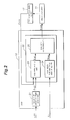
- Figure 2 shows an essential part of the present embodiment which comprises a target rear wheel toe angle setting unit for setting the target rear wheel toe angle of the left and right rear wheels of the motor vehicle, and a state variable detecting unit for detecting vehicle state variables representing the behavior of the vehicle similarly as that disclosed in patent document 1.
- the general structure of the rear wheel toe angle control system that changes the toe angle of the left and right rear wheels according to the deviation of the detected actual rear wheel toe angle from the target rear wheel toe angle may be omitted in the following disclosure.
- the electric actuator 11 and associated component parts may be described in the following without identifying if they are located on the left hand side or right hand side of the motor vehicle V because the ECU 12 performs a similar function for both the left and right electric actuators 11, and controls the left and right electric actuators 11 in a similar fashion.
- the second embodiment to distinguish the duty ratio D before and after a correction process, the duty ratio D before the correction process is referred to as “target duty ratio Dtgt", and the duty ratio D after the correction process is referred to as "commanded duty ratio Dcmd".
- the ECU 12 includes a target rear wheel toe angle setting unit 21 that determines a target rear wheel toe angle ⁇ rtgt according to the vehicle speed v and front wheel steering angle ⁇ f received from the corresponding sensors via an input interface not shown in the drawing, and a PID control unit 22 that determines a control command value (duty ratio D) according to the actual rear wheel toe angle ⁇ ract detected by the rear wheel toe angle sensor 17 and the target rear wheel toe angle ⁇ rtgt, and controls the actuation of the electric actuator 11 according to the determined control command value.
- a control command value duty ratio D
- the PID control unit 22 comprises a duty ratio setting unit 23, a maximum static frictional force computing unit 24 and a duty ratio correcting unit 25.
- the duty ratio setting unit 23 determines the target duty ratio Dtgt for the PWM control according to the deviation e of the actual rear wheel toe angle ⁇ ract detected by the rear wheel toe angle sensor 17 from the target rear wheel toe angle ⁇ rtgt, the integral value of the deviation e and the differential value of the deviation e.
- the maximum static frictional force computing unit 24 estimates the axial force Fa acting on the electric actuator 11 (feed screw mechanism 39) according to the lateral acceleration Gy detected by the lateral acceleration sensor 16, and computes the maximum static frictional force Ffmax by multiplying the static frictional coefficient ⁇ of the feed screw mechanism 39 to the estimated axial force Fa.
- the axial force Fa is estimated by looking up a map representing the relationship between the lateral acceleration Gy and the axial force Fa of the electric actuator 11 for the given suspension geometry of the rear suspension system 7, by using the lateral acceleration Gy as the index.
- the duty ratio correcting unit 25 compares the target duty ratio Dtgt with the lower limit of the duty ratio that is required for the electric actuator 11 to overcome the load at the time of start up or for the output F of the DC motor 37 to be greater than the maximum static frictional force Ffmax (start up duty ratio Ds). If the target duty ratio Dtgt is smaller than the start up duty ratio Ds, the target duty ratio Dtgt is corrected to the value of the start up duty ratio Ds, or the duty ratio D is boosted up. The duty ratio correcting unit 25 then forwards the commanded duty ratio Dcmd obtained by this correction process to the electric actuator 11.
- the start up condition that causes the duty ratio correcting unit 25 to carry out the correction process may be defined not only as the completion of the first PWM cycle as counted from the stand still condition where the duty ratio is zero but also as the completion of any number of initial PWM cycles or as the elapsing of any period of time from the stand still condition, and may be selected in dependence on the property of the electric actuator 11.
- the time period of about 100 ms is defined as the time period of the start up.
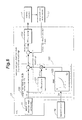
- the target duty ratio correction process by the ECU 12 is described in the following with reference to Figure 4 .
- the ECU 12 repeats the following target duty ratio correction process at a prescribed cycle time.
- the target rear wheel toe angle setting unit 21 determines the target rear wheel toe angle ⁇ rtgt (step S1)
- the duty ratio setting unit 23 determines the target duty ratio Dtgt according to the target rear wheel toe angle ⁇ rtgt and the actual rear wheel toe angle ⁇ ract (step S2).
- the duty ratio correcting unit 25 of the ECU 12 determines if the electric actuator 11 is in the start up condition (step S3). If the electric actuator 11 is not in the start up condition (No in step S3), the target duty ratio Dtgt determined in step S2 is forwarded as the commanded duty ratio Dcmd (step S7), and the current process is terminated.
- the maximum static frictional force computing unit 24 of the ECU 12 estimates the axial force Fa of the electric actuator 11 according to the lateral acceleration Gy, and computes the maximum static frictional force Ffmax of the feed screw mechanism 39 of the electric actuator 11 from the estimated axial force Fa (step S4).
- the duty ratio correcting unit 25 of the ECU 12 determines if the output F of the DC motor 37 based on the target duty ratio Dtgt is smaller than the maximum static frictional force Ffmax (step S5). If the output F is greater than the maximum static frictional force Ffmax (No in step S5), the target duty ratio Dtgt determined in step S2 is produced as the commanded duty ratio Dcmd (step S7), and the current process is terminated.
- step S5 If the output F is smaller than the maximum static frictional force Ffmax (Yes in step S5), the duty ratio correcting unit 25 corrects the target duty ratio Dtgt to the start up duty ratio Ds corresponding to the maximum static frictional force Ffmax so that the electric actuator 11 may be able to overcome the load thereto (step S6), and produces the corrected commanded duty ratio Dcmd (step S7) before terminating the current process.
- FIG. 5 is a time chart where the change in the rear wheel toe angle ⁇ r (ordinate) with time (abscissa) is shown.
- (A) indicates the change in the rear wheel toe angle ⁇ r as the vehicle V provided with a conventional rear wheel toe angle variable control system makes a turn
- (B) indicates the change in the rear wheel toe angle ⁇ r as the vehicle V provided with the rear wheel toe angle variable control system of the foregoing embodiment makes a turn.
- the target rear wheel toe angle ⁇ rtgt and actual rear wheel toe angle ⁇ ract substantially coincide with each other so that the electric actuator 11 demonstrates a highly favorable response property.
- the electric actuator 11 is enabled to operate properly immediately following the stand still condition.
- the response property of the motor vehicle V can be improved even when the motor vehicle V is making a turn without being affected by the operating condition of the motor vehicle V.
- the second embodiment of the present invention is described in the following with reference to Figures 6 to 10 .
- the rear wheel toe angle control system of the second embodiment is also implemented by the ECU 12.
- Figure 6 also shows an essential part of the present embodiment which comprises a target rear wheel toe angle setting unit for setting the target rear wheel toe angle of the left and right rear wheels of the motor vehicle, and a state variable detecting unit for detecting vehicle state variables representing the behavior of the vehicle similarly as that disclosed in patent document 1.
- the general structure of the rear wheel toe angle control system that changes the toe angle of the left and right rear wheels according to the deviation of the detected actual rear wheel toe angle from the target rear wheel toe angle may be omitted in the following disclosure.
- target rear wheel toe angle ⁇ rtgt target rear wheel toe angle before the correction process
- target rear wheel toe angle ⁇ rcmd target rear wheel toe angle after the correction process
- the ECU 12 computes a target rear wheel toe angle ⁇ rtgt according to the vehicle speed v and front wheel steering angle ⁇ f received via an input interface not shown in the drawing, and the computed target rear wheel toe angle ⁇ rtgt is forwarded to a target rear wheel toe angle correcting unit 120 provided in the ECU 12.
- a target rear wheel toe angle correcting unit 120 provided in the ECU 12.
- either one of the left and right rear wheels 5L and 5R represents both of the rear wheels, and is therefore denoted without any suffix that indicates the left hand side and right hand side of the vehicle body.
- the ECU 12 receives the output signal of the lateral acceleration sensor 16 representing the lateral acceleration Gy which is one of the state variables of the vehicle that represent the behavior of the motor vehicle V.
- the received lateral acceleration Gy is forwarded to the target rear wheel toe angle correcting unit 120.
- the target rear wheel toe angle ⁇ rtgt is determined from the front wheel steering angle ⁇ f, the vehicle speed v and other data, and makes transient changes during a turn.
- the increase in the load on the electric actuator 11 may impair the response property of the actual rear wheel toe angle ⁇ ract in following the target rear wheel toe angle ⁇ rtgt. Therefore, the differential value of the target rear wheel toe angle ⁇ rtgt may be considered as a measure of the change in the tracking performance of the rear wheel toe angle.
- the target rear wheel toe angle correcting unit 120 differentiates the received target rear wheel toe angle ⁇ rtgt by using a differentiator 121, and produces a differential value d ⁇ rtgt.
- the target rear wheel toe angle correcting unit 120 looks up a coefficient K corresponding to the received lateral acceleration Gy from a map 122 defining a relationship between the received lateral acceleration Gy and the coefficient K.
- the coefficient K is multiplied to the differential value d ⁇ rtgt of the target rear wheel toe angle ⁇ rtgt to produce a correction term K ⁇ d ⁇ rtgt.
- the correction term K ⁇ d ⁇ rtgt is proportional to the differential value d ⁇ rtgt of the target rear wheel toe angle.
- Figures 7a and 7b show the load on the electric actuator 11 for controlling the rear wheel toe angle ⁇ r when the vehicle is traveling straight ahead and when the vehicle is making a turn in the second embodiment of the present invention, respectively.
- the vehicle V is shown in plan view, and the relationship between the rear wheel 5 and electric actuator 11 is emphasized.
- the upper end of the drawing corresponds to the front end of the vehicle V
- the left hand side of the drawing corresponds to the center of the vehicle V.
- the electric actuator 11 is provided on the font side of the axial line of the rear wheel 5 indicated by a chain dot line
- the king pin K is located on the rear side of the axial line of the rear wheel 5.
- the electric actuator 11 can change the toe angle of the rear wheel by producing an axial force of a prescribed magnitude.
- Figure 7b when the vehicle V is making a turn, and the rear wheel 5 is subjected to a tire lateral force Fy, as the contact area of the tire that produces a lateral force directed in the axial direction of the rear wheel and the electric actuator 11 are located to the front of the king pin K in the present case, a compressive load is applied to the electric actuator 11.
- the axial force Fa of the electric actuator 11 changes depending on the tire lateral force Fy.
- Figure 8 shows the relationship between the lateral acceleration Gy and the axial force Fa of the electric actuator 11 in the arrangement illustrated in Figures 7a and 7b where the electric actuator 11 is subjected to a tensile axial force Fa under a normal condition.
- the axial force Fa of the electric actuator 11 moves from tension to compression, and the increase rate of the axial force Fa of the electric actuator 11 with the increase in the lateral acceleration Gy increases with the increase in the lateral acceleration Gy.
- This owes to the fact that the lateral force that is born by the outer wheel increases as the centrifugal force causes the load to shift toward the outer wheel.
- the rear wheel toe angle is controlled in such a manner that the actual rear wheel toe angle ⁇ ract is made to track or follow the target rear wheel toe angle ⁇ rtgt computed from the front wheel steering angle ⁇ f, the vehicle speed v and other data, but the actual rear wheel toe angle ⁇ ract may not closely track the target rear wheel toe angle ⁇ rtgt so much as desired owing to the changes in the axial force of the electric actuator 11 when the vehicle is making a turn.
- the coefficient K is defined such that the control gain is increased as the axial force of the electric actuator 11 increases due to the cornering of the vehicle V according to the relationship between the lateral acceleration Gy and the axial force Fa of the electric actuator 11 which is shown in Figure 8 .
- a correction term K ⁇ d ⁇ rtgt which accounts for the changes in the axial force Fa of the electric actuator 11 that depends on the lateral accleration Gy can be obtained.
- Figure 9 shows a map that can be stored in the memory of ECU 12 to produce a coefficient K for each given lateral acceleration.
- the correction term K ⁇ d ⁇ rtgt is added to the target rear wheel toe angle ⁇ rtgt to produce the commanded rear wheel toe angle ⁇ rcmd.
- a desired commanded rear wheel toe angle ⁇ rcmd which is appropriately advanced in phase with respect to the target rear wheel toe angle ⁇ rtgt can be obtained.
- the differentiator 121, the map 122 and other elements that are configured to compute the correction term K ⁇ d ⁇ rtgt form a load detection unit 123 for detecting the load to the electric actuator 11.
- a deviation e is computed by subtracting the actual rear wheel toe angle ⁇ ract detected by the rear wheel toe angle sensor 17 provided on the electric actuator 11 and forwarded to the ECU 12 via an input interface (not shown in the drawings) from the commanded rear wheel toe angle ⁇ rcmd.
- the deviation e is forwarded to a PID controller 124 which in turn produces, via an output interface (not shown in the drawings), a drive signal (duty ratio D) for actuating the electric actuator 11 so as to cancel this deviation e.
- the duty ratio D of the electric actuator 11 is boosted, and the delay in the tracking performance of the electric actuator 11 can be compensated.
- Figure 10 is a graph comparing the behavior of the second embodiment of the present invention with that of an example for comparison essentially consisting of a vehicle incorporated with a conventional rear wheel toe angle control system.
- Figure 10 essentially consists of a time chart comparing the embodiment of the present invention with the example for comparison with regard to the relationship between the target rear wheel toe angle ⁇ rtgt, the commanded rear wheel toe angle ⁇ rcmd and the actual rear wheel toe angle ⁇ ract.
- the actual rear wheel toe angle ⁇ ract indicated by the chain dot line demonstrates some phase delay with respect to the target rear wheel toe angle ⁇ rtgt indicated by the solid line.
- the actual rear wheel toe angle ⁇ ract indicated by the double dot chain dot line is allowed to coincide with the target rear wheel toe angle ⁇ rtgt, or the phase delay is eliminated.
- the rear wheel toe angle control system embodying the present invention even when the axial force acting on the electric actuator 11 for steering the rear wheel changes when the vehicle makes a turn, by executing a PID control by using the commanded rear wheel toe angle ⁇ rcmd obtained by adding the correction term K ⁇ d ⁇ rtgt to the target rear wheel toe angle ⁇ rtgt, as a feed forward process, the actual rear wheel toe angle ⁇ ract is allowed to track the target rear wheel toe angle ⁇ rtgt, and the four wheel steering vehicle is enabled to provide a highly stable dynamic performance.
- the present invention is not limited by the foregoing embodiments, but may be implemented in a number of different ways without departing from the spirit of the present invention.
- the lateral acceleration Gy was used for the detection of the axial force Fa of the electric actuator 11 in the first embodiment, but it is also possible to provide a fore and aft acceleration sensor 18 on the vehicle V, and the changes in the axial force of the electric actuator owing to the fore and aft acceleration may be accounted for.
- the change in the axial force owing to the lift of the vehicle body 1 in dependence on the vehicle speed may be accounted for.
- the system may be provided with a road surface condition detecting unit 19 for detecting the road surface condition such as the frictional coefficient of the road surface and account for the changes in the axial force owing to the road condition.
- the road surface condition detecting unit 19 may consist of a road surface frictional coefficient measuring device for directly measuring the frictional coefficient of the road surface, a road surface frictional coefficient estimating device for estimating the road surface frictional coefficient by using a non-contact measurement such as imaging measurement and laser measurement or a road surface irregularity detecting device for detecting the irregularities in the road surface by using a vertical acceleration sensor, among other possibilities.
- the drive source of the electric actuator 11 consisted on a DC motor 37, and the DC motor 37 was PWM controlled. However, it is also possible to directly control the applied DC voltage or the start up current, or to use an AC motor.
- the axial force Fa was estimated from the lateral acceleration Gy, and the maximum static frictional force Ffmax was computed from the estimated axial force Fa. However, it is also possible to directly compute the maximum static frictional force Ffmax from the running condition value of the vehicle V or to look up the maximum static frictional force Ffmax from a map.
- the target duty ratio Dtgt at the time of start up was corrected to the value of the start up duty ratio Ds without regard to the direction of the axial force Fa acting on the electric actuator.
- the target duty ratio Dtgt may be set to be greater than the start up duty ratio Ds by a prescribed amount or by a prescribed factor.
- the target duty ratio Dtgt was corrected to the start up duty ratio Ds only when the output F of the DC motor 37 is smaller than the maximum static frictional force Ffmax.
- the duty ratio correcting unit 25 corrected the target duty ratio Dtgt for a prescribed period of time at the time of start up.
- the duty ratio correcting unit 25 may correct the target duty ratio Dtgt only until the movement of the electric actuator 11 is detected. Thereby, the time period of correction by the duty ratio correcting unit 25 is minimized so that the waste in the consumption of energy may be avoided.
- the electric actuator fails to be started up for any incidental cause in spite of the use of the corrected commanded duty ratio Dcmd, the electric actuator 11 can be restarted in a reliable manner once the cause is removed.
Abstract
Description
- The present invention relates to a rear wheel toe angle control system that controls a rear wheel toe angle of a vehicle by using a rear wheel toe angle variable control unit according to the behavior of the vehicle.
- It is known, in a rear wheel steering system that steers the left and right rear wheels in a symmetric manner by laterally displaying the left and right suspension arms, to steer the rear wheels into a toe-in state depending on the dynamic condition of the vehicle such as the vehicle speed, front wheel steering angle and braking state, and change the toe-in angle in a progressive manner depending on the vehicle speed and front wheel steering angle. See
patent document 1. According to this technology, the turning capability of the vehicle may be improved in low speed range, and the stability of the vehicle can be improved in high speed range. Also, the tail swaying tendency of the vehicle during a turn and the reduction in the stability of the vehicle under a brake can be effectively prevented. - More recently, with the aim of improving the turning capability and the stability of the vehicle, various four wheel steering vehicles incorporated with a rear wheel toe angle varying device that allows the rear wheel toe angle to be individually changed have been developed. The rear wheel toe angle varying device may be constructed in a number of different ways. An electric actuator may be interposed between the vehicle body and a lateral link or a trailing link of the suspension system supporting each rear wheel as disclosed in patent document 2. In a double wishbone suspension system, a knuckle which is supported by the vehicle body via an upper arm and a lower arm using a ball joint in each of the arms may be additionally connected to the vehicle body via an electric actuator as disclosed in patent document 3. In any of such rear wheel toe angle varying devices, the toe angle of each rear wheel can be variably and individually controlled.
- A typical electric actuator for a rear wheel toe angle varying device consists of a linear actuator using an electric motor and a feed screw mechanism. The present applicant previously proposed an invention for preventing the inadvertent detachment of an output rod without increasing the size of the linear actuator (patent document 3). When a vehicle component is driven by such an electric actuator, a static friction is caused between the male thread and female thread of the feed screw mechanism, and this static friction impairs the tracking performance of the electric actuator when the actuator is operated from a stand still condition. To overcome the static resistance and improve the tracking performance of the linear actuator, it may be possible to increase the duty ratio of a PWM controlled electric actuator when starting the action of the actuator. See patent document 4 which describes a drive motor for driving a cooling fan.
-
- Patent Document 1:
JP05-178231A - Patent Document 2:
JP09-30438A - Patent Document 3:
JP2008-164017A - Patent Document 4:
JP2006-299810A - However, as the electric actuator for the rear wheel toe angle variable control system is interposed between the vehicle body and a suspension member, the axial force of the electric actuator may change depending on the running condition of the vehicle, and the change in the axial force in turn changes the maximum static frictional force. Therefore, even if the duty ratio in the PWM control is great enough for the electric actuator to overcome the maximum static frictional force at the time of start up, when the electric actuator is subjected to a large axial force such as when the vehicle is cornering, the output of the electric actuator may be great enough to start moving or there may be some delay in the response of the electric actuator.
- In a vehicle equipped with a rear wheel toe angle variable control system, the actual rear wheel toe angle is controlled so as to track a target rear wheel toe angle computed from the front wheel steering angle and vehicle speed. Typically, this control action consists of a PID feedback control based on the deviation between the actual rear wheel toe angle and target rear wheel toe angle, and this deviation determines the input voltage for the electric actuator. This input voltage is PWM controlled in driving the electric motor. However, when the vehicle makes a turn, the electric actuator is subjected to an axial force, and this may impair the tracking performance of the electric actuator.
- The present invention was made in view of such problems of the prior art, and has a primary object to provide a rear wheel toe angle control system that can prevent the impairment of the tracking performance of the electric actuator and enable the rear wheel toe angle control system to ensure the stability of the vehicle even when the electric actuator for steering the rear wheels according to the operating condition of the vehicle is subjected to an axial force.
- To achieve such objects, the present invention provides a rear wheel toe angle control system (12) for changing a rear wheel toe angle (δr) of a vehicle (V) by using an electric actuator (11), comprising: a target rear wheel toe angle setting unit (21) for setting a target rear wheel toe angle (δrtgt); an actual rear wheel toe angle detecting unit (17) for detecting an actual rear wheel toe angle (δract); a drive control unit (22, 124) that drives the electric actuator by a control value (D) based on a difference (e) between the target rear wheel toe angle (δrtgt) and actual rear wheel toe angle (δract); a load detecting unit (24, 123) for detecting load acting upon the electric actuator; and a correcting unit (25, 120) for correcting the control value according to the load acting on the electric actuator.
- According to the present invention, even when the load on the electric actuator changes depending on the running condition of the vehicle, as the control value for the electric actuator is boosted by the correcting unit, the tracking performance of the electric actuator is prevented from being impaired.
- According to a certain aspect of the present invention, the electric actuator includes an electric motor (37) and a power transmission mechanism (39), and the correcting unit is configured to correct the control value so that an output (F) of the electric motor is greater than a maximum static frictional force (Ffmax) of the power transmission mechanism that depends on the load acting on the electric motor (Dcmd > Ds). Thereby, the even when the maximum static frictional force of the power transmission mechanism increases owing to the running condition of the vehicle, the response property of the electric actuator is prevented from being impaired. Therefore, the vehicle motion can be stabilized without regard to the running condition of the vehicle.
- According to another aspect of the present invention, the electric actuator consists of a linear actuator including a feed screw mechanism (39), and an axial force detector (16) for detecting an axial force (Fa) of the electric actuator is provided on the electric actuator, the load detecting unit (24) being configured to detect the load (Ffmax) of the electric actuator from the axial force of the electric actuator. The use of the linear actuator allows the power transmission mechanism to be minimized in size, and the load of the electric actuator can be directly obtained from the axial force of the electric actuator by taking into account the configuration of the power transmission mechanism.
- According to yet another aspect of the present invention, the axial force detector is configured to detect at least one of a lateral acceleration (Gy) of a vehicle body, a fore and aft acceleration (Gx) of the vehicle body, a vehicle speed (v) and a road surface condition (µ). In this arrangement, the maximum frictional force of the feed screw mechanism or the target control value that is required for the electric actuator to start off can be estimated, and the precision in the estimation of the maximum frictional force can be increased by using two or more of these parameters.
- According to yet another embodiment of the present invention, the control value comprises a duty ratio for PWM control. Thereby, a highly responsive rear wheel toe angle control can be achieved in a vehicle provided with a DC power source.
- According to yet another embodiment of the present invention, the correcting unit is configured to correct the control value over a prescribed time period at a time of starting up the electric actuator. Thereby, the amount of correction by the correcting unit can be freely selected, and a waste in the energy consumption can be minimized by terminating the boosting of the control value after elapsing of the period selected for the electric actuator to be able to start off.
- According to yet another aspect of the present invention, the rear wheel toe angle control system of the present invention may further comprise a start up condition detecting unit (17) for detecting a start up condition of the electric actuator, the correcting unit being configured to continue correcting the control value until the electric actuator has started moving at a start up thereof. Thereby, the time period for the boost up correction can be minimized, and waste in the energy consumption can be avoided. Furthermore, when the electric actuator fails to be started up for any incidental cause in spite of the boosting of the control value, the electric actuator can be restarted in a reliable manner once the cause is removed.
- According to yet another aspect of the present invention, the correcting unit (120) is configured to correct the control value by computing a correction term (K × dδrtgt) by multiplying a coefficient (K) to a differentiated value (dδrtgt) of the target rear wheel toe angle, and adding the correction term to the target rear wheel toe angle (δrtgt). By thus adding the correction term based on the differentiated value of the target rear wheel toe angle by feed forward to the target rear wheel toe angle, the target rear wheel toe angle is advanced in phase so that the delay in the tracking performance can be avoided even when the load on the electric actuator is increased.
- According to yet another aspect of the present invention, the electric actuator consists of a linear actuator, and an axial force detector (16) for detecting an axial force (Fa) of the electric actuator is provided on the electric actuator, the correcting unit (160) being configured to correct the control value by computing a correction term (K × dδrtgt) that depends on the axial force of the electric actuator, and adding the correction term to the target rear wheel toe angle (δrtgt).
By thus adding the correction term that depends on the axial force of the electric actuator by feed forward to the target rear wheel toe angle, the target rear wheel toe angle is advanced in phase depending the axial force of the electric actuator which may vary depending on the running condition of the vehicle so that the delay in the tracking performance can be avoided even when the load on the electric actuator is increased. - According to yet another aspect of the present invention, the correcting unit is configured to correct the control value by computing a correction term (K × dδrtgt) by multiplying a coefficient (K) based on the axial force of the electric actuator to a differentiated value of the target rear wheel toe angle, and adding the correction term to the target rear wheel toe angle (δrtgt). By thus adding a correction term that depends on the actuating speed of the electric actuator and the axial force of the electric actuator to the target rear wheel toe angle, the delay in the tracking performance can be improved without regard to the operating condition of the electric actuator and the running condition of the vehicle.
- According to the present invention, even when the axial force acting on the electric actuator changes depending on the running condition of the vehicle, the performance of the system in tracking the target rear wheel toe angle is prevented from being impaired, and the vehicle behavior can be stabilized.
-
-
Figure 1 is a simplified plan view of the overall structure of a four wheeled vehicle embodying the present invention; -
Figure 2 is a block diagram showing the overall structure of a rear wheel toe angle control system given as a first embodiment of the present invention; -
Figure 3 represents a map showing the relationship between the axial force of the electric actuator and the lateral acceleration in the first embodiment of the present invention; -
Figure 4 is a flowchart of the target duty ratio correction process used in the first embodiment of the present invention; -
Figure 5 is a time chart showing the response of the rear wheel toe angle in the rear wheel toe angle control system of the first embodiment of the present invention; -
Figure 6 is a block diagram showing the overall structure of a rear wheel toe angle control system given as a second embodiment of the present invention; -
Figures 7a and 7b are diagrams showing the load of the electric actuator for controlling the rear wheel toe angle when the vehicle is traveling straight ahead and making a turn in the second embodiment of the present invention, respectively; -
Figure 8 is a chart showing the relationship between the axial force of the electric actuator and the lateral acceleration in the second embodiment of the present invention; -
Figure 9 is a chart (map) showing the relationship between the lateral acceleration and the coefficient that is to be multiplied to the target rear wheel toe angle in the second embodiment of the present invention; and -
Figure 10 is a time chart comparing relationship between the target rear wheel toe angle and the actual rear wheel toe angle in the second embodiment of the present invention and an example for comparison. - A motor vehicle V incorporated with a rear wheel toe angle variable control unit 10 embodying the present invention is described in the following with reference to the appended drawings. In the following description, each wheel and the associated tire and electric actuator are denoted with corresponding numerals followed by a letter L or R depending on which side of the vehicle the particular component is located. For instance, the left and rear wheels are denoted with 5L and 5R, respectively. When such components are collectively referred to, they are denoted with the corresponding numeral. For instance, the rear wheels may be denoted simply with
numeral 5. - Referring to
Figure 1 , the motor vehicle V comprises a pair offront wheels tires rear wheels tires vehicle body 1 viacorresponding suspension systems - The motor vehicle V is further provided with a front
wheel steering device 9 that directly steers the left and rightfront wheels steering wheel 8 via a rack and pinion mechanism, and a pair of rear wheel toe anglevariable control units rear wheels electric actuators 11Land 11 R incorporated in the correspondingwheel suspension systems - The
electric actuator 11 incorporated in each rear wheel toe angle variable control unit 10 may consist of a per se known linear actuator, and the detailed description thereof is omitted in this disclosure. The electric actuator disclosed in patent document 3, for instance, may be used for the present invention. As shown in an enlarged view included inFigure 1 , theelectric actuator 11 may comprise a brush-type DCelectric motor 37 received in ahousing 32 attached to the vehicle body and configured to be pulse width modulation (PWM) controlled, areduction gear unit 38 interposed between the output shaft of theDC motor 37 and the male thread of afeed screw mechanism 39, and anoutput rod 35 formed with the female thread of thefeed screw mechanism 39 and connected to the correspondingrear wheel 5. - The motor vehicle V is provided with an ECU (electronic control unit) 12 for controlling the overall operation of the various onboard systems, a
vehicle speed sensor 13, a front wheelsteering angle sensor 14, ayaw rate sensor 15, alateral acceleration sensor 16 and other sensors that are not shown in the drawings. The detection signals of the various sensors are forwarded to theECU 12 for the purpose of controlling the various control actions of the motor vehicle V. The front wheelsteering angle sensor 14 detects the steering angle of thesteering wheel 8, and the front wheel steering angle δf is computed from the detection signal of the front wheelsteering angle sensor 14. Thelateral acceleration sensor 16 detects the lateral acceleration Gy of thevehicle body 1. TheECU 12 forms an essential part of the rear wheel toe angle variable control unit 10, and thelateral acceleration sensor 16 forms an essential part of the axial force detecting unit for detecting the axial force Fa of theelectric actuator 11. - Each
electric actuator toe angle sensor output rod 35 thereof. Each rear wheeltoe angle sensor 17 detects the stroke of the correspondingelectric actuator 11 by detecting the displacement of a permanent magnet placed on theoutput rod 35 with a differential transformer mounted on the vehicle body adjacent to the permanent magnet, and theECU 12 receives the output signal of the rear wheeltoe angle sensor - The
ECU 12 essentially consists of a computer, and comprises a processor (CPU) for executing various arithmetic computations, random access memory (RAM) for provided a storage area for temporarily storing various kinds of data and a work area for the CPU to execute the arithmetic computations, read only memory (ROM) for storing the programs to be executed by the CPU and various kinds of data that are required for the arithmetic computations, re-writable non-volatile memory for storing the results of the arithmetic computations and some of the data obtained from various parts of the engine, drivers, a peripheral circuit and an input/output interface. TheECU 12 is connected to thevarious sensors 13 to 17 andelectric actuators 11 via a communication line which consists of a CAN (controlled area network) in the illustrated embodiment so that theelectric actuators rear wheels various sensors 13 to 16. - In this motor vehicle V incorporated with the system described above, the toe in and toe out of the two
rear wheels electric actuators electric actuators other actuator ECU 12 may actuate therear wheels 5 to a toe out condition in acceleration and to a toe in condition in deceleration, and/or may steer therear wheels 5 in the same phase as the front wheels 3 when making a turn at a speed higher than a prescribed threshold speed and in the opposite phase to the front wheels 3 when making a turn at a speed lower than the prescribed threshold speed. - The first embodiment of the present invention is described in the following with reference to
Figures 2 to 5 . The rear wheel toe angle control system of the first embodiment is implemented by theECU 12.Figure 2 shows an essential part of the present embodiment which comprises a target rear wheel toe angle setting unit for setting the target rear wheel toe angle of the left and right rear wheels of the motor vehicle, and a state variable detecting unit for detecting vehicle state variables representing the behavior of the vehicle similarly as that disclosed inpatent document 1. The general structure of the rear wheel toe angle control system that changes the toe angle of the left and right rear wheels according to the deviation of the detected actual rear wheel toe angle from the target rear wheel toe angle may be omitted in the following disclosure. In the appended drawings, theelectric actuator 11 and associated component parts may be described in the following without identifying if they are located on the left hand side or right hand side of the motor vehicle V because theECU 12 performs a similar function for both the left and rightelectric actuators 11, and controls the left and rightelectric actuators 11 in a similar fashion. The same is true with the second embodiment. Also, in the following disclosure, to distinguish the duty ratio D before and after a correction process, the duty ratio D before the correction process is referred to as "target duty ratio Dtgt", and the duty ratio D after the correction process is referred to as "commanded duty ratio Dcmd". - As shown in
Figure 2 , theECU 12 includes a target rear wheel toeangle setting unit 21 that determines a target rear wheel toe angle δrtgt according to the vehicle speed v and front wheel steering angle δf received from the corresponding sensors via an input interface not shown in the drawing, and aPID control unit 22 that determines a control command value (duty ratio D) according to the actual rear wheel toe angle δract detected by the rear wheeltoe angle sensor 17 and the target rear wheel toe angle δrtgt, and controls the actuation of theelectric actuator 11 according to the determined control command value. - The
PID control unit 22 comprises a dutyratio setting unit 23, a maximum static frictionalforce computing unit 24 and a dutyratio correcting unit 25. The dutyratio setting unit 23 determines the target duty ratio Dtgt for the PWM control according to the deviation e of the actual rear wheel toe angle δract detected by the rear wheeltoe angle sensor 17 from the target rear wheel toe angle δrtgt, the integral value of the deviation e and the differential value of the deviation e. - The maximum static frictional
force computing unit 24 estimates the axial force Fa acting on the electric actuator 11 (feed screw mechanism 39) according to the lateral acceleration Gy detected by thelateral acceleration sensor 16, and computes the maximum static frictional force Ffmax by multiplying the static frictional coefficient µ of thefeed screw mechanism 39 to the estimated axial force Fa. The axial force Fa is estimated by looking up a map representing the relationship between the lateral acceleration Gy and the axial force Fa of theelectric actuator 11 for the given suspension geometry of therear suspension system 7, by using the lateral acceleration Gy as the index. For instance, when theelectric actuator 11 is provided on the same side (either front side or rear side) of the king pin of therear wheel 5 as the contact area of the tire 4 to which the lateral acceleration acts, the greater the lateral acceleration Gy which is directed outward of the curve is, the greater the compressive (retracting) axial force Fa becomes, as shown inFigure 3 . When the vehicle is traveling straight ahead or when the lateral acceleration Gy is zero, because the suspension geometry involves a slight positive camber, the axial force Fa consists of a slight tension (extension). - The duty
ratio correcting unit 25 compares the target duty ratio Dtgt with the lower limit of the duty ratio that is required for theelectric actuator 11 to overcome the load at the time of start up or for the output F of theDC motor 37 to be greater than the maximum static frictional force Ffmax (start up duty ratio Ds). If the target duty ratio Dtgt is smaller than the start up duty ratio Ds, the target duty ratio Dtgt is corrected to the value of the start up duty ratio Ds, or the duty ratio D is boosted up. The dutyratio correcting unit 25 then forwards the commanded duty ratio Dcmd obtained by this correction process to theelectric actuator 11. - The start up condition that causes the duty
ratio correcting unit 25 to carry out the correction process may be defined not only as the completion of the first PWM cycle as counted from the stand still condition where the duty ratio is zero but also as the completion of any number of initial PWM cycles or as the elapsing of any period of time from the stand still condition, and may be selected in dependence on the property of theelectric actuator 11. In the illustrated embodiment, the time period of about 100 ms is defined as the time period of the start up. - The target duty ratio correction process by the
ECU 12 is described in the following with reference toFigure 4 . Once the engine of thevehicle 12 is started, theECU 12 repeats the following target duty ratio correction process at a prescribed cycle time. First of all, in theECU 12, the target rear wheel toeangle setting unit 21 determines the target rear wheel toe angle δrtgt (step S1), and the dutyratio setting unit 23 determines the target duty ratio Dtgt according to the target rear wheel toe angle δrtgt and the actual rear wheel toe angle δract (step S2). The dutyratio correcting unit 25 of theECU 12 determines if theelectric actuator 11 is in the start up condition (step S3). If theelectric actuator 11 is not in the start up condition (No in step S3), the target duty ratio Dtgt determined in step S2 is forwarded as the commanded duty ratio Dcmd (step S7), and the current process is terminated. - On the other hand, if the
electric actuator 11 is in the start up condition (Yes in step S3), the maximum static frictionalforce computing unit 24 of theECU 12 estimates the axial force Fa of theelectric actuator 11 according to the lateral acceleration Gy, and computes the maximum static frictional force Ffmax of thefeed screw mechanism 39 of theelectric actuator 11 from the estimated axial force Fa (step S4). The dutyratio correcting unit 25 of theECU 12 determines if the output F of theDC motor 37 based on the target duty ratio Dtgt is smaller than the maximum static frictional force Ffmax (step S5). If the output F is greater than the maximum static frictional force Ffmax (No in step S5), the target duty ratio Dtgt determined in step S2 is produced as the commanded duty ratio Dcmd (step S7), and the current process is terminated. - If the output F is smaller than the maximum static frictional force Ffmax (Yes in step S5), the duty
ratio correcting unit 25 corrects the target duty ratio Dtgt to the start up duty ratio Ds corresponding to the maximum static frictional force Ffmax so that theelectric actuator 11 may be able to overcome the load thereto (step S6), and produces the corrected commanded duty ratio Dcmd (step S7) before terminating the current process. - The mode of operation of the rear wheel toe angle variable control unit 10 of the foregoing embodiment is described in the following with reference to
Figure 5. Figure 5 is a time chart where the change in the rear wheel toe angle δr (ordinate) with time (abscissa) is shown. (A) indicates the change in the rear wheel toe angle δr as the vehicle V provided with a conventional rear wheel toe angle variable control system makes a turn, and (B) indicates the change in the rear wheel toe angle δr as the vehicle V provided with the rear wheel toe angle variable control system of the foregoing embodiment makes a turn. As shown in these time charts, in the conventional rear wheel toe angle variable control system, there is a certain phase delay between the target rear wheel toe angle δrtgt and actual rear wheel toe angle δract so that an initial delay at the start of the operation impairs the response property of theelectric actuator 11. On the other hand, according to the rear wheel toe angle variable control unit 10 embodying the present invention, the target rear wheel toe angle δrtgt and actual rear wheel toe angle δract substantially coincide with each other so that theelectric actuator 11 demonstrates a highly favorable response property. - As can be appreciated from the foregoing discussion, by correcting the target duty ratio Dtgt at the start up of the
electric actuator 11 such that the commanded duty ratio Dcmd may not be smaller than the start up duty ratio Ds, theelectric actuator 11 is enabled to operate properly immediately following the stand still condition. By computing the start up duty ratio Ds according to the axial force Fa of theelectric actuator 11 which can be obtained from the lateral acceleration Gy, and correcting the target duty ratio Dtgt so that the commanded duty ratio Dcmd may not be smaller than the start up duty ratio, the response property of the motor vehicle V can be improved even when the motor vehicle V is making a turn without being affected by the operating condition of the motor vehicle V. By thus allowing the rear wheel toe angle δr to be changed in a highly responsive manner, the rear wheel toe angle variable control unit 10 is enabled to improve the motion stability of the motor vehicle V in a favorable manner. - The second embodiment of the present invention is described in the following with reference to
Figures 6 to 10 . The rear wheel toe angle control system of the second embodiment is also implemented by theECU 12.Figure 6 also shows an essential part of the present embodiment which comprises a target rear wheel toe angle setting unit for setting the target rear wheel toe angle of the left and right rear wheels of the motor vehicle, and a state variable detecting unit for detecting vehicle state variables representing the behavior of the vehicle similarly as that disclosed inpatent document 1. The general structure of the rear wheel toe angle control system that changes the toe angle of the left and right rear wheels according to the deviation of the detected actual rear wheel toe angle from the target rear wheel toe angle may be omitted in the following disclosure. Also, in the following disclosure, to distinguish the target rear wheel toe angle before and after a correction process, the target rear wheel toe angle before the correction process is referred to as "target rear wheel toe angle δrtgt", and the target rear wheel toe angle after the correction process is referred to as "commanded rear wheel toe angle δrcmd". - Referring to
Figure 6 , theECU 12 computes a target rear wheel toe angle δrtgt according to the vehicle speed v and front wheel steering angle δf received via an input interface not shown in the drawing, and the computed target rear wheel toe angle δrtgt is forwarded to a target rear wheel toeangle correcting unit 120 provided in theECU 12. InFigure 6 , either one of the left and rightrear wheels - The
ECU 12 receives the output signal of thelateral acceleration sensor 16 representing the lateral acceleration Gy which is one of the state variables of the vehicle that represent the behavior of the motor vehicle V. The received lateral acceleration Gy is forwarded to the target rear wheel toeangle correcting unit 120. - The target rear wheel toe angle δrtgt is determined from the front wheel steering angle δf, the vehicle speed v and other data, and makes transient changes during a turn. The greater the transient changes of the target rear wheel toe angle δrtgt are, the greater the load on the
electric actuator 11 becomes. The increase in the load on theelectric actuator 11 may impair the response property of the actual rear wheel toe angle δract in following the target rear wheel toe angle δrtgt. Therefore, the differential value of the target rear wheel toe angle δrtgt may be considered as a measure of the change in the tracking performance of the rear wheel toe angle. Thus, the target rear wheel toeangle correcting unit 120 differentiates the received target rear wheel toe angle δrtgt by using adifferentiator 121, and produces a differential value dδrtgt. - The target rear wheel toe
angle correcting unit 120 looks up a coefficient K corresponding to the received lateral acceleration Gy from amap 122 defining a relationship between the received lateral acceleration Gy and the coefficient K. The coefficient K is multiplied to the differential value dδrtgt of the target rear wheel toe angle δrtgt to produce a correction term K × dδrtgt. In other words, the correction term K × dδrtgt is proportional to the differential value dδrtgt of the target rear wheel toe angle. - The meaning of the coefficient K is discussed in the following with reference to
Figures 7 to 9 .Figures 7a and 7b show the load on theelectric actuator 11 for controlling the rear wheel toe angle δr when the vehicle is traveling straight ahead and when the vehicle is making a turn in the second embodiment of the present invention, respectively. The vehicle V is shown in plan view, and the relationship between therear wheel 5 andelectric actuator 11 is emphasized. InFigures 7a and 7b , the upper end of the drawing corresponds to the front end of the vehicle V, and the left hand side of the drawing corresponds to the center of the vehicle V. Theelectric actuator 11 is provided on the font side of the axial line of therear wheel 5 indicated by a chain dot line, and the king pin K is located on the rear side of the axial line of therear wheel 5. - Referring to
Figure 7a , when the vehicle is traveling straight ahead, theelectric actuator 11 can change the toe angle of the rear wheel by producing an axial force of a prescribed magnitude. However, as shown inFigure 7b , when the vehicle V is making a turn, and therear wheel 5 is subjected to a tire lateral force Fy, as the contact area of the tire that produces a lateral force directed in the axial direction of the rear wheel and theelectric actuator 11 are located to the front of the king pin K in the present case, a compressive load is applied to theelectric actuator 11. Thus, the axial force Fa of theelectric actuator 11 changes depending on the tire lateral force Fy. -
Figure 8 shows the relationship between the lateral acceleration Gy and the axial force Fa of theelectric actuator 11 in the arrangement illustrated inFigures 7a and 7b where theelectric actuator 11 is subjected to a tensile axial force Fa under a normal condition. As shown inFigure 8 , when the lateral acceleration Gy is directed toward the outer wheel as in the case illustrated inFigure 7b , the axial force Fa of theelectric actuator 11 moves from tension to compression, and the increase rate of the axial force Fa of theelectric actuator 11 with the increase in the lateral acceleration Gy increases with the increase in the lateral acceleration Gy. This owes to the fact that the lateral force that is born by the outer wheel increases as the centrifugal force causes the load to shift toward the outer wheel. In the case of the vehicle equipped with the conventional rear wheel toe angle control system, the rear wheel toe angle is controlled in such a manner that the actual rear wheel toe angle δract is made to track or follow the target rear wheel toe angle δrtgt computed from the front wheel steering angle δf, the vehicle speed v and other data, but the actual rear wheel toe angle δract may not closely track the target rear wheel toe angle δrtgt so much as desired owing to the changes in the axial force of theelectric actuator 11 when the vehicle is making a turn. - Therefore, as shown in
Figure 9 , the coefficient K is defined such that the control gain is increased as the axial force of theelectric actuator 11 increases due to the cornering of the vehicle V according to the relationship between the lateral acceleration Gy and the axial force Fa of theelectric actuator 11 which is shown inFigure 8 . By multiplying the coefficient K thus defined to the differential value dδrtgt of the target rear wheel toe angle, a correction term K × dδrtgt which accounts for the changes in the axial force Fa of theelectric actuator 11 that depends on the lateral accleration Gy can be obtained.Figure 9 shows a map that can be stored in the memory ofECU 12 to produce a coefficient K for each given lateral acceleration. - Referring to the functional block diagram of
Figure 6 once again, the correction term K × dδrtgt is added to the target rear wheel toe angle δrtgt to produce the commanded rear wheel toe angle δrcmd. By adding the product of the differential value dδrtgt of the target rear wheel toe angle and the coefficient K or the correction term K × dδrtgt to the target rear wheel toe angle δrtgt by feed forward, a desired commanded rear wheel toe angle δrcmd which is appropriately advanced in phase with respect to the target rear wheel toe angle δrtgt can be obtained. In other words, thedifferentiator 121, themap 122 and other elements that are configured to compute the correction term K × dδrtgt form aload detection unit 123 for detecting the load to theelectric actuator 11. - A deviation e is computed by subtracting the actual rear wheel toe angle δract detected by the rear wheel
toe angle sensor 17 provided on theelectric actuator 11 and forwarded to theECU 12 via an input interface (not shown in the drawings) from the commanded rear wheel toe angle δrcmd. The deviation e is forwarded to aPID controller 124 which in turn produces, via an output interface (not shown in the drawings), a drive signal (duty ratio D) for actuating theelectric actuator 11 so as to cancel this deviation e. By using the commanded rear wheel toe angle δrcmd which has the correction term K × dδrtgt added thereto by feed forward as the command signal for theelectric actuator 11, the duty ratio D of theelectric actuator 11 is boosted, and the delay in the tracking performance of theelectric actuator 11 can be compensated. -
Figure 10 is a graph comparing the behavior of the second embodiment of the present invention with that of an example for comparison essentially consisting of a vehicle incorporated with a conventional rear wheel toe angle control system.Figure 10 essentially consists of a time chart comparing the embodiment of the present invention with the example for comparison with regard to the relationship between the target rear wheel toe angle δrtgt, the commanded rear wheel toe angle δrcmd and the actual rear wheel toe angle δract. - Referring to
Figure 10 , in the case of the example for comparison, the actual rear wheel toe angle δract indicated by the chain dot line demonstrates some phase delay with respect to the target rear wheel toe angle δrtgt indicated by the solid line. On the other hand, in the case of the embodiment of the present invention, by using the commanded rear wheel toe angle δrcmd (indicated by the dotted line) obtained by correcting the target rear wheel toe angle δrtgt so as to advance the phase thereof, the actual rear wheel toe angle δract indicated by the double dot chain dot line is allowed to coincide with the target rear wheel toe angle δrtgt, or the phase delay is eliminated. Thus, according to the rear wheel toe angle control system embodying the present invention, even when the axial force acting on theelectric actuator 11 for steering the rear wheel changes when the vehicle makes a turn, by executing a PID control by using the commanded rear wheel toe angle δrcmd obtained by adding the correction term K × dδrtgt to the target rear wheel toe angle δrtgt, as a feed forward process, the actual rear wheel toe angle δract is allowed to track the target rear wheel toe angle δrtgt, and the four wheel steering vehicle is enabled to provide a highly stable dynamic performance. - The preferred embodiments of the present invention have been described, but the present invention is not limited by the foregoing embodiments, but may be implemented in a number of different ways without departing from the spirit of the present invention. For instance, the lateral acceleration Gy was used for the detection of the axial force Fa of the
electric actuator 11 in the first embodiment, but it is also possible to provide a fore andaft acceleration sensor 18 on the vehicle V, and the changes in the axial force of the electric actuator owing to the fore and aft acceleration may be accounted for. Alternatively, the change in the axial force owing to the lift of thevehicle body 1 in dependence on the vehicle speed may be accounted for. If desired, the system may be provided with a road surfacecondition detecting unit 19 for detecting the road surface condition such as the frictional coefficient of the road surface and account for the changes in the axial force owing to the road condition. The road surfacecondition detecting unit 19 may consist of a road surface frictional coefficient measuring device for directly measuring the frictional coefficient of the road surface, a road surface frictional coefficient estimating device for estimating the road surface frictional coefficient by using a non-contact measurement such as imaging measurement and laser measurement or a road surface irregularity detecting device for detecting the irregularities in the road surface by using a vertical acceleration sensor, among other possibilities. - In the first embodiment, the drive source of the
electric actuator 11 consisted on aDC motor 37, and theDC motor 37 was PWM controlled. However, it is also possible to directly control the applied DC voltage or the start up current, or to use an AC motor. In the first embodiment, the axial force Fa was estimated from the lateral acceleration Gy, and the maximum static frictional force Ffmax was computed from the estimated axial force Fa. However, it is also possible to directly compute the maximum static frictional force Ffmax from the running condition value of the vehicle V or to look up the maximum static frictional force Ffmax from a map. - In the first embodiment, the target duty ratio Dtgt at the time of start up was corrected to the value of the start up duty ratio Ds without regard to the direction of the axial force Fa acting on the electric actuator. However, it is also possible to change the value of the start up duty ratio Ds and/or change the time period of correction at the time of start up depending on the direction of the axial force Fa. Also, the target duty ratio Dtgt may be set to be greater than the start up duty ratio Ds by a prescribed amount or by a prescribed factor. In the first embodiment, the target duty ratio Dtgt was corrected to the start up duty ratio Ds only when the output F of the
DC motor 37 is smaller than the maximum static frictional force Ffmax. However, it is also possible to always use a duty ratio greater than a prescribed level at the start up even when the maximum static frictional force Ffmax is small. - In the first embodiment, the duty
ratio correcting unit 25 corrected the target duty ratio Dtgt for a prescribed period of time at the time of start up. However, the dutyratio correcting unit 25 may correct the target duty ratio Dtgt only until the movement of theelectric actuator 11 is detected. Thereby, the time period of correction by the dutyratio correcting unit 25 is minimized so that the waste in the consumption of energy may be avoided. Also, according to this arrangement, when the electric actuator fails to be started up for any incidental cause in spite of the use of the corrected commanded duty ratio Dcmd, theelectric actuator 11 can be restarted in a reliable manner once the cause is removed. - The relationship between the lateral acceleration Gy and the coefficent K was given by a map as shown in
Figure 9 in the second embodiment of the present invention. It is also possible to obtain the lateral load of the vehicle by applying a delay filter to the output of the front wheel steering angle sensor, and the map may show the relationship between this lateral load and the corresponding coefficient. These and other changes can be made to the concrete structure and arrangement of the various devices and units of the present invention without departing from the scope and spirit of the present invention. -
- 1
- vehicle body
- 5
- rear wheel
- 10
- rear wheel toe angle variable control system
- 11
- electric actuator
- 12
- ECU (rear wheel toe angle variable control unit)
- 13
- vehicle speed sensor
- 16
- lateral acceleration sensor (axial force detecting unit)
- 17
- rear wheel toe angle sensor
(rear wheel toe angle detecting unit, start up detecting unit) - 18
- fore and aft acceleration sensor
- 19
- road surface condition detecting unit
- 21
- target rear wheel toe angle setting unit
- 22
- PID control unit (drive control unit)
- 24
- maximum static frictional force computing unit (load detecting unit)
- 25
- duty ratio correcting unit (correcting unit)
- 37
- DC motor
- 39
- feed screw mechanism
- 120
- target rear wheel toe angle correcting unit (correcting unit)
- 123
- load detecting unit
- 124
- PID control unit (drive control unit)
- V
- motor vehicle
- δr
- rear wheel toe angle
- δrtgt
- target rear wheel toe angle
- dδrtgt
- differentiated value of target rear wheel toe angle
- δrcmd
- commanded rear wheel toe angle
- δract
- actual rear wheel toe angle
- e
- deviation
- D
- duty ratio (control value)
- Dtgt
- target duty ratio
- Dcmd
- commanded duty ratio
- Ds
- start up duty ratio
- Gy
- lateral acceleration
- F
- motor output
- Ffmax
- maximum static frictional force
- K
- coefficient
- K × dδrtgt
- correction term
Claims (10)
- A rear wheel toe angle control system for changing a rear wheel toe angle of a vehicle by using an electric actuator, comprising:a target rear wheel toe angle setting unit for setting a target rear wheel toe angle;an actual rear wheel toe angle detecting unit for detecting an actual rear wheel toe angle;a drive control unit that drives the electric actuator by a control value based on a difference between the target rear wheel toe angle and actual rear wheel toe angle;a load detecting unit for detecting load acting upon the electric actuator; anda correcting unit for correcting the control value according to the load acting on the electric actuator.
- The rear wheel toe angle control system according to claim 1, wherein the electric actuator includes an electric motor and a power transmission mechanism, and the correcting unit is configured to correct the control value so that an output of the electric motor is greater than a maximum static frictional force of the power transmission mechanism that depends on the load acting on the electric motor.
- The rear wheel toe angle control system according to claim 2, wherein the electric actuator consists of a linear actuator including a feed screw mechanism, and an axial force detector for detecting an axial force of the electric actuator is provided on the electric actuator, the load detecting unit being configured to detect the load of the electric actuator from the axial force of the electric actuator.
- The rear wheel toe angle control system according to claim 3, wherein the axial force detector is configured to detect at least one of a lateral acceleration of a vehicle body, a fore and aft acceleration of the vehicle body, a vehicle speed and a road surface condition.
- The rear wheel toe angle control system according to claim 2, wherein the control value comprises a duty ratio for PWM control.
- The rear wheel toe angle control system according to claim 2, wherein the correcting unit is configured to correct the control value over a prescribed time period at a time of starting up the electric actuator.
- The rear wheel toe angle control system according to claim 2, further comprising a start up condition detecting unit for detecting a start up condition of the electric actuator, the correcting unit being configured to continue correcting the control value until the electric actuator has started moving at a start up thereof.
- The rear wheel toe angle control system according to claim 1, wherein the correcting unit is configured to correct the control value by computing a correction term by multiplying a coefficient to a differentiated value of the target rear wheel toe angle, and adding the correction term to the target rear wheel toe angle.
- The rear wheel toe angle control system according to claim 8, wherein the electric actuator consists of a linear actuator, and an axial force detector for detecting an axial force of the electric actuator is provided on the electric actuator, the correcting unit being configured to correct the control value by computing a correction term that depends on the axial force of the electric actuator, and adding the correction term to the target rear wheel toe angle.
- The rear wheel toe angle control system according to claim 9, wherein the correcting unit is configured to correct the control value by computing a correction term by multiplying a coefficient based on the axial force of the electric actuator to a differentiated value of the target rear wheel toe angle, and adding the correction term to the target rear wheel toe angle.
Applications Claiming Priority (3)
| Application Number | Priority Date | Filing Date | Title |
|---|---|---|---|
| JP2009056053 | 2009-03-10 | ||
| JP2009082771 | 2009-03-30 | ||
| PCT/JP2010/001664 WO2010103810A1 (en) | 2009-03-10 | 2010-03-09 | Vehicle rear wheel toe angle control device |
Publications (3)
| Publication Number | Publication Date |
|---|---|
| EP2407370A1 true EP2407370A1 (en) | 2012-01-18 |
| EP2407370A4 EP2407370A4 (en) | 2012-07-25 |
| EP2407370B1 EP2407370B1 (en) | 2014-09-24 |
Family
ID=42728106
Family Applications (1)
| Application Number | Title | Priority Date | Filing Date |
|---|---|---|---|
| EP10750567.9A Not-in-force EP2407370B1 (en) | 2009-03-10 | 2010-03-09 | Vehicle rear wheel toe angle control device |
Country Status (4)
| Country | Link |
|---|---|
| US (1) | US8463506B2 (en) |
| EP (1) | EP2407370B1 (en) |
| JP (1) | JP5432984B2 (en) |
| WO (1) | WO2010103810A1 (en) |
Cited By (2)
| Publication number | Priority date | Publication date | Assignee | Title |
|---|---|---|---|---|
| CN103010303A (en) * | 2011-09-28 | 2013-04-03 | 比亚迪股份有限公司 | Vehicle control system and vehicle comprising system |
| US8755972B2 (en) * | 2009-12-25 | 2014-06-17 | Honda Motor Co., Ltd. | Rear wheel toe angle control system for a vehicle |
Families Citing this family (11)
| Publication number | Priority date | Publication date | Assignee | Title |
|---|---|---|---|---|
| JP5602789B2 (en) * | 2012-05-30 | 2014-10-08 | 本田技研工業株式会社 | Rear wheel toe angle control device for vehicle |
| JP5738234B2 (en) * | 2012-05-30 | 2015-06-17 | 本田技研工業株式会社 | Rear wheel toe angle variable vehicle |
| DE102014104176A1 (en) * | 2013-03-28 | 2014-10-02 | Fuji Jukogyo Kabushiki Kaisha | suspension device |
| US10053148B2 (en) | 2015-06-15 | 2018-08-21 | GM Global Technology Operations LLC | Toe optimization system for a vehicle |
| JP2017030471A (en) * | 2015-07-31 | 2017-02-09 | Ntn株式会社 | Rear wheel steering control device |
| DE102017208554A1 (en) * | 2017-05-19 | 2018-11-22 | Bayerische Motoren Werke Aktiengesellschaft | Wheel suspension for an at least slightly actively steerable rear wheel of a two-lane vehicle, axle with a suspension and vehicle with a suspension |
| KR102277285B1 (en) * | 2017-06-30 | 2021-07-14 | 현대모비스 주식회사 | Apparatus for controlling rear wheel steering and method thereof |
| JP2019131013A (en) * | 2018-01-30 | 2019-08-08 | 株式会社ジェイテクト | Steering control device |
| JP6586181B2 (en) * | 2018-02-20 | 2019-10-02 | 本田技研工業株式会社 | Vehicle steering system |
| DE102019204294B4 (en) | 2019-03-27 | 2022-10-20 | Vitesco Technologies Germany Gmbh | Method for controlling a dog clutch and arrangement comprising a transmission and a gear actuator |
| EP3990297A4 (en) * | 2019-06-28 | 2023-08-30 | Ree Automotive Ltd | Device and method for double-arm suspension and in-wheel steering |
Citations (3)
| Publication number | Priority date | Publication date | Assignee | Title |
|---|---|---|---|---|
| EP1892179A1 (en) * | 2006-08-25 | 2008-02-27 | Honda Motor Co., Ltd | Variable rear wheel toe angle control system for a vehicle |
| US20080054577A1 (en) * | 2006-08-29 | 2008-03-06 | Honda Motor Co., Ltd. | Variable rear wheel toe angle control system for a vehicle |
| JP2008221996A (en) * | 2007-03-12 | 2008-09-25 | Honda Motor Co Ltd | Steering system |
Family Cites Families (21)
| Publication number | Priority date | Publication date | Assignee | Title |
|---|---|---|---|---|
| JPH0517823A (en) | 1991-07-10 | 1993-01-26 | Sumitomo Metal Ind Ltd | Production of electromagnetic soft iron for thick plate excellent in magnetic shielding property |
| JPH05178231A (en) | 1991-12-28 | 1993-07-20 | Mazda Motor Corp | Rear wheel steering device for vehicle |
| JP3476972B2 (en) | 1995-07-17 | 2003-12-10 | 本田技研工業株式会社 | Rear wheel steering device |
| US6033041A (en) * | 1995-09-20 | 2000-03-07 | Mitsubishi Jidosha Kogyo Kabushiki Kaisha | Regenerative braking control system for electric vehicle |
| JPH11321685A (en) * | 1998-05-11 | 1999-11-24 | Toyota Motor Corp | Steering control device for vehicle |
| JP4586258B2 (en) | 2000-11-02 | 2010-11-24 | 日産自動車株式会社 | Vehicle steering control device |
| JP4841772B2 (en) * | 2001-09-28 | 2011-12-21 | いすゞ自動車株式会社 | Common rail fuel injection control device |
| JP4305158B2 (en) | 2003-12-12 | 2009-07-29 | 日産自動車株式会社 | Vehicle toe angle control device |
| JP2006029981A (en) | 2004-07-15 | 2006-02-02 | Taisho Pharmaceut Co Ltd | Analyzing method of compounded components of cold medicine and migration liquid for analysis |
| JP2006062505A (en) | 2004-08-26 | 2006-03-09 | Nissan Motor Co Ltd | Suspension device for vehicle |
| JP4517810B2 (en) | 2004-10-13 | 2010-08-04 | 日産自動車株式会社 | Vehicle steering control device |
| JP2006160005A (en) | 2004-12-03 | 2006-06-22 | Toyota Motor Corp | Vehicular steering device |
| JP4418404B2 (en) * | 2005-03-09 | 2010-02-17 | ジヤトコ株式会社 | Clutch control device and clutch control method |
| JP2006299810A (en) | 2005-04-15 | 2006-11-02 | Nissan Motor Co Ltd | Cooling fan drive control device for vehicle |
| JP4274189B2 (en) * | 2006-02-13 | 2009-06-03 | トヨタ自動車株式会社 | Vehicle control system |
| EP1880921A3 (en) * | 2006-07-19 | 2009-07-15 | Nsk Ltd | Controller for electric power steering apparatus |
| JP5109342B2 (en) * | 2006-11-15 | 2012-12-26 | 日本精工株式会社 | Electric power steering device |
| JP4319217B2 (en) | 2006-12-27 | 2009-08-26 | 本田技研工業株式会社 | Telescopic actuator |
| US8050819B2 (en) * | 2007-02-16 | 2011-11-01 | Honda Motor Co., Ltd. | Alignment changing control device and fuel consumption management device |
| JP2008280027A (en) | 2007-04-11 | 2008-11-20 | Honda Motor Co Ltd | Electric power steering device |
| US8180547B2 (en) * | 2009-03-27 | 2012-05-15 | Ford Global Technologies, Llc | Telematics system and method for traction reporting and control in a vehicle |
-
2010
- 2010-03-09 EP EP10750567.9A patent/EP2407370B1/en not_active Not-in-force
- 2010-03-09 WO PCT/JP2010/001664 patent/WO2010103810A1/en active Application Filing
- 2010-03-09 JP JP2011503707A patent/JP5432984B2/en active Active
- 2010-03-09 US US13/254,357 patent/US8463506B2/en active Active
Patent Citations (3)
| Publication number | Priority date | Publication date | Assignee | Title |
|---|---|---|---|---|
| EP1892179A1 (en) * | 2006-08-25 | 2008-02-27 | Honda Motor Co., Ltd | Variable rear wheel toe angle control system for a vehicle |
| US20080054577A1 (en) * | 2006-08-29 | 2008-03-06 | Honda Motor Co., Ltd. | Variable rear wheel toe angle control system for a vehicle |
| JP2008221996A (en) * | 2007-03-12 | 2008-09-25 | Honda Motor Co Ltd | Steering system |
Non-Patent Citations (1)
| Title |
|---|
| See also references of WO2010103810A1 * |
Cited By (3)
| Publication number | Priority date | Publication date | Assignee | Title |
|---|---|---|---|---|
| US8755972B2 (en) * | 2009-12-25 | 2014-06-17 | Honda Motor Co., Ltd. | Rear wheel toe angle control system for a vehicle |
| CN103010303A (en) * | 2011-09-28 | 2013-04-03 | 比亚迪股份有限公司 | Vehicle control system and vehicle comprising system |
| CN103010303B (en) * | 2011-09-28 | 2016-01-13 | 比亚迪股份有限公司 | A kind of vehicle control system and comprise the vehicle of this system |
Also Published As
| Publication number | Publication date |
|---|---|
| US20110313624A1 (en) | 2011-12-22 |
| US8463506B2 (en) | 2013-06-11 |
| EP2407370A4 (en) | 2012-07-25 |
| JPWO2010103810A1 (en) | 2012-09-13 |
| JP5432984B2 (en) | 2014-03-05 |
| WO2010103810A1 (en) | 2010-09-16 |
| EP2407370B1 (en) | 2014-09-24 |
Similar Documents
| Publication | Publication Date | Title |
|---|---|---|
| EP2407370B1 (en) | Vehicle rear wheel toe angle control device | |
| US7991532B2 (en) | Wheel control device and control device | |
| US8050818B2 (en) | Roll stiffness control apparatus of vehicle | |
| US8670905B2 (en) | Vehicle stability control method and system | |
| US20150274201A1 (en) | Drive supporting device, operation detecting device, and controller | |
| US20130073146A1 (en) | Steering system and steering control apparatus | |
| JP5432990B2 (en) | Rear wheel toe angle control device and electric actuator reference position calibration method in rear wheel toe angle control device | |
| EP2322412A1 (en) | Vehicle with a variable rear toe angle | |
| JP2005343315A (en) | Vehicular steering device | |
| JP2578142B2 (en) | Auxiliary steering system for vehicles | |
| JP2864962B2 (en) | Rear wheel steering device | |
| JP3882894B2 (en) | Steering reaction force control device | |
| US8831838B2 (en) | Rear wheel toe angle control system | |
| US10086669B2 (en) | Stabilizer control device | |
| JPS60191875A (en) | Controlling method of steerage for vehicles | |
| JPH03231015A (en) | Alignment control device for wheel | |
| JP2970163B2 (en) | Wheel camber angle control device | |
| JP2004255943A (en) | Control device of vehicle | |
| EP2236394B1 (en) | Rear wheel steering control system | |
| JP5313714B2 (en) | Electric power steering device | |
| JP5303333B2 (en) | Vehicle rear wheel steering control device | |
| JP5271662B2 (en) | Power steering device | |
| JP5254143B2 (en) | Vehicle control device | |
| JP4929696B2 (en) | Vehicle behavior control device | |
| US20190283734A1 (en) | Vehicle stability control device |
Legal Events
| Date | Code | Title | Description |
|---|---|---|---|
| PUAI | Public reference made under article 153(3) epc to a published international application that has entered the european phase |
Free format text: ORIGINAL CODE: 0009012 |
|
| 17P | Request for examination filed |
Effective date: 20110826 |
|
| AK | Designated contracting states |
Kind code of ref document: A1 Designated state(s): AT BE BG CH CY CZ DE DK EE ES FI FR GB GR HR HU IE IS IT LI LT LU LV MC MK MT NL NO PL PT RO SE SI SK SM TR |
|
| DAX | Request for extension of the european patent (deleted) | ||
| A4 | Supplementary search report drawn up and despatched |
Effective date: 20120627 |
|
| RIC1 | Information provided on ipc code assigned before grant |
Ipc: B62D 17/00 20060101ALI20120621BHEP Ipc: B60G 17/016 20060101ALI20120621BHEP Ipc: B62D 6/00 20060101AFI20120621BHEP Ipc: B62D 7/08 20060101ALI20120621BHEP Ipc: B60W 30/02 20120101ALI20120621BHEP Ipc: B62D 5/04 20060101ALI20120621BHEP Ipc: B62D 137/00 20060101ALI20120621BHEP Ipc: B62D 113/00 20060101ALI20120621BHEP Ipc: B62D 7/14 20060101ALI20120621BHEP Ipc: B62D 101/00 20060101ALI20120621BHEP Ipc: B62D 111/00 20060101ALI20120621BHEP Ipc: B60G 17/015 20060101ALI20120621BHEP Ipc: B62D 7/15 20060101ALI20120621BHEP |
|
| 17Q | First examination report despatched |
Effective date: 20120718 |
|
| GRAP | Despatch of communication of intention to grant a patent |
Free format text: ORIGINAL CODE: EPIDOSNIGR1 |
|
| INTG | Intention to grant announced |
Effective date: 20140415 |
|
| GRAS | Grant fee paid |
Free format text: ORIGINAL CODE: EPIDOSNIGR3 |
|
| GRAA | (expected) grant |
Free format text: ORIGINAL CODE: 0009210 |
|
| AK | Designated contracting states |
Kind code of ref document: B1 Designated state(s): AT BE BG CH CY CZ DE DK EE ES FI FR GB GR HR HU IE IS IT LI LT LU LV MC MK MT NL NO PL PT RO SE SI SK SM TR |
|
| REG | Reference to a national code |
Ref country code: GB Ref legal event code: FG4D |
|
| REG | Reference to a national code |
Ref country code: CH Ref legal event code: EP |
|
| REG | Reference to a national code |
Ref country code: AT Ref legal event code: REF Ref document number: 688475 Country of ref document: AT Kind code of ref document: T Effective date: 20141015 |
|
| REG | Reference to a national code |
Ref country code: IE Ref legal event code: FG4D |
|
| REG | Reference to a national code |
Ref country code: DE Ref legal event code: R096 Ref document number: 602010019143 Country of ref document: DE Effective date: 20141106 |
|
| PG25 | Lapsed in a contracting state [announced via postgrant information from national office to epo] |
Ref country code: SE Free format text: LAPSE BECAUSE OF FAILURE TO SUBMIT A TRANSLATION OF THE DESCRIPTION OR TO PAY THE FEE WITHIN THE PRESCRIBED TIME-LIMIT Effective date: 20140924 Ref country code: LT Free format text: LAPSE BECAUSE OF FAILURE TO SUBMIT A TRANSLATION OF THE DESCRIPTION OR TO PAY THE FEE WITHIN THE PRESCRIBED TIME-LIMIT Effective date: 20140924 Ref country code: GR Free format text: LAPSE BECAUSE OF FAILURE TO SUBMIT A TRANSLATION OF THE DESCRIPTION OR TO PAY THE FEE WITHIN THE PRESCRIBED TIME-LIMIT Effective date: 20141225 Ref country code: FI Free format text: LAPSE BECAUSE OF FAILURE TO SUBMIT A TRANSLATION OF THE DESCRIPTION OR TO PAY THE FEE WITHIN THE PRESCRIBED TIME-LIMIT Effective date: 20140924 Ref country code: NO Free format text: LAPSE BECAUSE OF FAILURE TO SUBMIT A TRANSLATION OF THE DESCRIPTION OR TO PAY THE FEE WITHIN THE PRESCRIBED TIME-LIMIT Effective date: 20141224 |
|
| REG | Reference to a national code |
Ref country code: LT Ref legal event code: MG4D Ref country code: NL Ref legal event code: VDEP Effective date: 20140924 |
|
| PG25 | Lapsed in a contracting state [announced via postgrant information from national office to epo] |
Ref country code: CY Free format text: LAPSE BECAUSE OF FAILURE TO SUBMIT A TRANSLATION OF THE DESCRIPTION OR TO PAY THE FEE WITHIN THE PRESCRIBED TIME-LIMIT Effective date: 20140924 Ref country code: HR Free format text: LAPSE BECAUSE OF FAILURE TO SUBMIT A TRANSLATION OF THE DESCRIPTION OR TO PAY THE FEE WITHIN THE PRESCRIBED TIME-LIMIT Effective date: 20140924 Ref country code: LV Free format text: LAPSE BECAUSE OF FAILURE TO SUBMIT A TRANSLATION OF THE DESCRIPTION OR TO PAY THE FEE WITHIN THE PRESCRIBED TIME-LIMIT Effective date: 20140924 |
|
| REG | Reference to a national code |
Ref country code: AT Ref legal event code: MK05 Ref document number: 688475 Country of ref document: AT Kind code of ref document: T Effective date: 20140924 |
|
| PG25 | Lapsed in a contracting state [announced via postgrant information from national office to epo] |
Ref country code: NL Free format text: LAPSE BECAUSE OF FAILURE TO SUBMIT A TRANSLATION OF THE DESCRIPTION OR TO PAY THE FEE WITHIN THE PRESCRIBED TIME-LIMIT Effective date: 20140924 |
|
| PG25 | Lapsed in a contracting state [announced via postgrant information from national office to epo] |
Ref country code: RO Free format text: LAPSE BECAUSE OF FAILURE TO SUBMIT A TRANSLATION OF THE DESCRIPTION OR TO PAY THE FEE WITHIN THE PRESCRIBED TIME-LIMIT Effective date: 20140924 Ref country code: PT Free format text: LAPSE BECAUSE OF FAILURE TO SUBMIT A TRANSLATION OF THE DESCRIPTION OR TO PAY THE FEE WITHIN THE PRESCRIBED TIME-LIMIT Effective date: 20150126 Ref country code: EE Free format text: LAPSE BECAUSE OF FAILURE TO SUBMIT A TRANSLATION OF THE DESCRIPTION OR TO PAY THE FEE WITHIN THE PRESCRIBED TIME-LIMIT Effective date: 20140924 Ref country code: CZ Free format text: LAPSE BECAUSE OF FAILURE TO SUBMIT A TRANSLATION OF THE DESCRIPTION OR TO PAY THE FEE WITHIN THE PRESCRIBED TIME-LIMIT Effective date: 20140924 Ref country code: IS Free format text: LAPSE BECAUSE OF FAILURE TO SUBMIT A TRANSLATION OF THE DESCRIPTION OR TO PAY THE FEE WITHIN THE PRESCRIBED TIME-LIMIT Effective date: 20150124 Ref country code: ES Free format text: LAPSE BECAUSE OF FAILURE TO SUBMIT A TRANSLATION OF THE DESCRIPTION OR TO PAY THE FEE WITHIN THE PRESCRIBED TIME-LIMIT Effective date: 20140924 Ref country code: SK Free format text: LAPSE BECAUSE OF FAILURE TO SUBMIT A TRANSLATION OF THE DESCRIPTION OR TO PAY THE FEE WITHIN THE PRESCRIBED TIME-LIMIT Effective date: 20140924 |
|
| PG25 | Lapsed in a contracting state [announced via postgrant information from national office to epo] |
Ref country code: AT Free format text: LAPSE BECAUSE OF FAILURE TO SUBMIT A TRANSLATION OF THE DESCRIPTION OR TO PAY THE FEE WITHIN THE PRESCRIBED TIME-LIMIT Effective date: 20140924 Ref country code: PL Free format text: LAPSE BECAUSE OF FAILURE TO SUBMIT A TRANSLATION OF THE DESCRIPTION OR TO PAY THE FEE WITHIN THE PRESCRIBED TIME-LIMIT Effective date: 20140924 |
|
| PGFP | Annual fee paid to national office [announced via postgrant information from national office to epo] |
Ref country code: GB Payment date: 20150319 Year of fee payment: 6 |
|
| REG | Reference to a national code |
Ref country code: DE Ref legal event code: R097 Ref document number: 602010019143 Country of ref document: DE |
|
| PG25 | Lapsed in a contracting state [announced via postgrant information from national office to epo] |
Ref country code: DK Free format text: LAPSE BECAUSE OF FAILURE TO SUBMIT A TRANSLATION OF THE DESCRIPTION OR TO PAY THE FEE WITHIN THE PRESCRIBED TIME-LIMIT Effective date: 20140924 |
|
| PLBE | No opposition filed within time limit |
Free format text: ORIGINAL CODE: 0009261 |
|
| STAA | Information on the status of an ep patent application or granted ep patent |
Free format text: STATUS: NO OPPOSITION FILED WITHIN TIME LIMIT |
|
| PG25 | Lapsed in a contracting state [announced via postgrant information from national office to epo] |
Ref country code: IT Free format text: LAPSE BECAUSE OF FAILURE TO SUBMIT A TRANSLATION OF THE DESCRIPTION OR TO PAY THE FEE WITHIN THE PRESCRIBED TIME-LIMIT Effective date: 20140924 |
|
| 26N | No opposition filed |
Effective date: 20150625 |
|
| PG25 | Lapsed in a contracting state [announced via postgrant information from national office to epo] |
Ref country code: MC Free format text: LAPSE BECAUSE OF FAILURE TO SUBMIT A TRANSLATION OF THE DESCRIPTION OR TO PAY THE FEE WITHIN THE PRESCRIBED TIME-LIMIT Effective date: 20140924 Ref country code: LU Free format text: LAPSE BECAUSE OF FAILURE TO SUBMIT A TRANSLATION OF THE DESCRIPTION OR TO PAY THE FEE WITHIN THE PRESCRIBED TIME-LIMIT Effective date: 20150309 |
|
| REG | Reference to a national code |
Ref country code: CH Ref legal event code: PL |
|
| REG | Reference to a national code |
Ref country code: FR Ref legal event code: ST Effective date: 20151130 |
|
| REG | Reference to a national code |
Ref country code: IE Ref legal event code: MM4A |
|
| PG25 | Lapsed in a contracting state [announced via postgrant information from national office to epo] |
Ref country code: LI Free format text: LAPSE BECAUSE OF NON-PAYMENT OF DUE FEES Effective date: 20150331 Ref country code: CH Free format text: LAPSE BECAUSE OF NON-PAYMENT OF DUE FEES Effective date: 20150331 Ref country code: IE Free format text: LAPSE BECAUSE OF NON-PAYMENT OF DUE FEES Effective date: 20150309 |
|
| PG25 | Lapsed in a contracting state [announced via postgrant information from national office to epo] |
Ref country code: FR Free format text: LAPSE BECAUSE OF NON-PAYMENT OF DUE FEES Effective date: 20150331 Ref country code: SI Free format text: LAPSE BECAUSE OF FAILURE TO SUBMIT A TRANSLATION OF THE DESCRIPTION OR TO PAY THE FEE WITHIN THE PRESCRIBED TIME-LIMIT Effective date: 20140924 |
|
| PGFP | Annual fee paid to national office [announced via postgrant information from national office to epo] |
Ref country code: DE Payment date: 20160302 Year of fee payment: 7 |
|
| GBPC | Gb: european patent ceased through non-payment of renewal fee |
Effective date: 20160309 |
|
| PG25 | Lapsed in a contracting state [announced via postgrant information from national office to epo] |
Ref country code: MT Free format text: LAPSE BECAUSE OF FAILURE TO SUBMIT A TRANSLATION OF THE DESCRIPTION OR TO PAY THE FEE WITHIN THE PRESCRIBED TIME-LIMIT Effective date: 20140924 |
|
| PG25 | Lapsed in a contracting state [announced via postgrant information from national office to epo] |
Ref country code: GB Free format text: LAPSE BECAUSE OF NON-PAYMENT OF DUE FEES Effective date: 20160309 |
|
| PG25 | Lapsed in a contracting state [announced via postgrant information from national office to epo] |
Ref country code: HU Free format text: LAPSE BECAUSE OF FAILURE TO SUBMIT A TRANSLATION OF THE DESCRIPTION OR TO PAY THE FEE WITHIN THE PRESCRIBED TIME-LIMIT; INVALID AB INITIO Effective date: 20100309 Ref country code: SM Free format text: LAPSE BECAUSE OF FAILURE TO SUBMIT A TRANSLATION OF THE DESCRIPTION OR TO PAY THE FEE WITHIN THE PRESCRIBED TIME-LIMIT Effective date: 20140924 Ref country code: BG Free format text: LAPSE BECAUSE OF FAILURE TO SUBMIT A TRANSLATION OF THE DESCRIPTION OR TO PAY THE FEE WITHIN THE PRESCRIBED TIME-LIMIT Effective date: 20140924 |
|
| PG25 | Lapsed in a contracting state [announced via postgrant information from national office to epo] |
Ref country code: TR Free format text: LAPSE BECAUSE OF FAILURE TO SUBMIT A TRANSLATION OF THE DESCRIPTION OR TO PAY THE FEE WITHIN THE PRESCRIBED TIME-LIMIT Effective date: 20140924 |
|
| PG25 | Lapsed in a contracting state [announced via postgrant information from national office to epo] |
Ref country code: BE Free format text: LAPSE BECAUSE OF FAILURE TO SUBMIT A TRANSLATION OF THE DESCRIPTION OR TO PAY THE FEE WITHIN THE PRESCRIBED TIME-LIMIT Effective date: 20140924 |
|
| REG | Reference to a national code |
Ref country code: DE Ref legal event code: R119 Ref document number: 602010019143 Country of ref document: DE |
|
| PG25 | Lapsed in a contracting state [announced via postgrant information from national office to epo] |
Ref country code: DE Free format text: LAPSE BECAUSE OF NON-PAYMENT OF DUE FEES Effective date: 20171003 |
|
| PG25 | Lapsed in a contracting state [announced via postgrant information from national office to epo] |
Ref country code: MK Free format text: LAPSE BECAUSE OF FAILURE TO SUBMIT A TRANSLATION OF THE DESCRIPTION OR TO PAY THE FEE WITHIN THE PRESCRIBED TIME-LIMIT Effective date: 20140924 |