EP2407355A1 - Relay valve and method for operating same - Google Patents
Relay valve and method for operating same Download PDFInfo
- Publication number
- EP2407355A1 EP2407355A1 EP11173389A EP11173389A EP2407355A1 EP 2407355 A1 EP2407355 A1 EP 2407355A1 EP 11173389 A EP11173389 A EP 11173389A EP 11173389 A EP11173389 A EP 11173389A EP 2407355 A1 EP2407355 A1 EP 2407355A1
- Authority
- EP
- European Patent Office
- Prior art keywords
- control
- valve
- pressure
- relay
- relay valve
- Prior art date
- Legal status (The legal status is an assumption and is not a legal conclusion. Google has not performed a legal analysis and makes no representation as to the accuracy of the status listed.)
- Granted
Links
- 238000000034 method Methods 0.000 title claims abstract description 9
- 238000013022 venting Methods 0.000 description 11
- ORQBXQOJMQIAOY-UHFFFAOYSA-N nobelium Chemical compound [No] ORQBXQOJMQIAOY-UHFFFAOYSA-N 0.000 description 10
- 238000009423 ventilation Methods 0.000 description 10
- 238000010586 diagram Methods 0.000 description 4
- 238000005273 aeration Methods 0.000 description 3
- 230000000694 effects Effects 0.000 description 2
- 230000007613 environmental effect Effects 0.000 description 2
- 238000010926 purge Methods 0.000 description 2
- 238000012546 transfer Methods 0.000 description 2
- 230000009471 action Effects 0.000 description 1
- 230000000740 bleeding effect Effects 0.000 description 1
- 238000011109 contamination Methods 0.000 description 1
- 230000008878 coupling Effects 0.000 description 1
- 238000010168 coupling process Methods 0.000 description 1
- 238000005859 coupling reaction Methods 0.000 description 1
- 230000007423 decrease Effects 0.000 description 1
- 230000001934 delay Effects 0.000 description 1
- 230000003111 delayed effect Effects 0.000 description 1
- 230000001419 dependent effect Effects 0.000 description 1
- 238000013461 design Methods 0.000 description 1
- 239000000428 dust Substances 0.000 description 1
- 238000004519 manufacturing process Methods 0.000 description 1
- 230000007246 mechanism Effects 0.000 description 1
- 230000036316 preload Effects 0.000 description 1
- 238000003825 pressing Methods 0.000 description 1
- 230000009467 reduction Effects 0.000 description 1
- 239000010802 sludge Substances 0.000 description 1
- 239000007921 spray Substances 0.000 description 1
- 238000003860 storage Methods 0.000 description 1
- 238000012360 testing method Methods 0.000 description 1
- 230000007704 transition Effects 0.000 description 1
- 238000011144 upstream manufacturing Methods 0.000 description 1
- XLYOFNOQVPJJNP-UHFFFAOYSA-N water Substances O XLYOFNOQVPJJNP-UHFFFAOYSA-N 0.000 description 1
Images

Classifications
-
- B—PERFORMING OPERATIONS; TRANSPORTING
- B60—VEHICLES IN GENERAL
- B60T—VEHICLE BRAKE CONTROL SYSTEMS OR PARTS THEREOF; BRAKE CONTROL SYSTEMS OR PARTS THEREOF, IN GENERAL; ARRANGEMENT OF BRAKING ELEMENTS ON VEHICLES IN GENERAL; PORTABLE DEVICES FOR PREVENTING UNWANTED MOVEMENT OF VEHICLES; VEHICLE MODIFICATIONS TO FACILITATE COOLING OF BRAKES
- B60T15/00—Construction arrangement, or operation of valves incorporated in power brake systems and not covered by groups B60T11/00 or B60T13/00
- B60T15/02—Application and release valves
- B60T15/18—Triple or other relay valves which allow step-wise application or release and which are actuated by brake-pipe pressure variation to connect brake cylinders or equivalent to compressed air or vacuum source or atmosphere
- B60T15/182—Trailer brake valves
-
- B—PERFORMING OPERATIONS; TRANSPORTING
- B60—VEHICLES IN GENERAL
- B60T—VEHICLE BRAKE CONTROL SYSTEMS OR PARTS THEREOF; BRAKE CONTROL SYSTEMS OR PARTS THEREOF, IN GENERAL; ARRANGEMENT OF BRAKING ELEMENTS ON VEHICLES IN GENERAL; PORTABLE DEVICES FOR PREVENTING UNWANTED MOVEMENT OF VEHICLES; VEHICLE MODIFICATIONS TO FACILITATE COOLING OF BRAKES
- B60T15/00—Construction arrangement, or operation of valves incorporated in power brake systems and not covered by groups B60T11/00 or B60T13/00
- B60T15/02—Application and release valves
- B60T15/18—Triple or other relay valves which allow step-wise application or release and which are actuated by brake-pipe pressure variation to connect brake cylinders or equivalent to compressed air or vacuum source or atmosphere
- B60T15/20—Triple or other relay valves which allow step-wise application or release and which are actuated by brake-pipe pressure variation to connect brake cylinders or equivalent to compressed air or vacuum source or atmosphere controlled by two fluid pressures
- B60T15/206—Trailer brake valves
-
- B—PERFORMING OPERATIONS; TRANSPORTING
- B60—VEHICLES IN GENERAL
- B60T—VEHICLE BRAKE CONTROL SYSTEMS OR PARTS THEREOF; BRAKE CONTROL SYSTEMS OR PARTS THEREOF, IN GENERAL; ARRANGEMENT OF BRAKING ELEMENTS ON VEHICLES IN GENERAL; PORTABLE DEVICES FOR PREVENTING UNWANTED MOVEMENT OF VEHICLES; VEHICLE MODIFICATIONS TO FACILITATE COOLING OF BRAKES
- B60T7/00—Brake-action initiating means
- B60T7/12—Brake-action initiating means for automatic initiation; for initiation not subject to will of driver or passenger
- B60T7/20—Brake-action initiating means for automatic initiation; for initiation not subject to will of driver or passenger specially for trailers, e.g. in case of uncoupling of or overrunning by trailer
Definitions
- the invention relates to a relay valve with a control piston and a sleeve, both of which are movable in an axial direction, wherein a first elastic element is provided, which acts on the sleeve in the axial direction with a biasing force
- the invention further relates to a method of operating a relay valve with a control piston and a sleeve, both of which are movable in an axial direction, wherein the collar is subjected in the axial direction with a biasing force.
- the present disclosure relates to a relay valve, in particular a relay valve of an electrically operated parking brake system, as for example from DE 10 2008 007 877 B3 is known.
- the venting of the control chamber of the central control valve means that is in particular the venting of the spring brake cylinder loading and venting relay valve, via an outside of the vehicle frame arranged vent, which thus environmental influences from the outside, for example spray, jet water, dust or sludge, is exposed.
- a corresponding component must be provided for protection, which opens in the venting direction and locks in the opposite direction. Suitable for this purpose are grooved rings, slightly preloaded rubber washers or sintered filters.
- the invention has for its object to solve the above-mentioned problem also in connection with an electrically actuated parking brake system.
- the relay valve according to the invention builds on the generic state of the art in that a second elastic element is provided which acts on the control piston in the axial direction with a further biasing force. In this way, the characteristic of the relay valve is shifted so that the Ausreten a certain output pressure, a higher control pressure is necessary than would be necessary without the second elastic element. It is therefore a higher robustness against undesired pressure increase in the control line of the relay valve, in particular by leaks achieved.
- the second elastic element is a spring.
- a spring is a comparatively robust and yet inexpensive to manufacture component, which can be easily integrated into the design of existing relay valve, so that no complete redesign is necessary.
- control piston and the sleeve are mutually independently movable.
- the second elastic element only influences the provided output pressure as a function of the control pressure.
- the invention further relates to an electrically actuated parking brake system for a vehicle, in particular a commercial vehicle, with a relay valve according to the invention.
- the invention is based on the generic method in that the control piston is acted upon in the axial direction with a further biasing force.
- the advantages and special features of the relay valve according to the invention are also implemented in the context of a method. This also applies to the particularly preferred embodiment of the method according to the invention given below.
- the inventive method is advantageously further formed in that the control piston is moved independently of the sleeve.
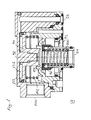
- FIG. 1 shows a sectional view of a relay valve.
- the illustrated relay valve 58 includes a relay control input 56, a supply port 92, a vent 84 and a vent port 104.
- a control piston 94 and a collar 96 are movably disposed along an axial direction 98.
- the sleeve 96 is thereby pressed by a first elastic element 100, which is designed as a spring, in the axial direction 98 against a valve seat 124.
- the housing 122 may be designed in one piece but in particular also as a multi-part housing, for example as a housing lower part which is connected to an upper housing part, for example via two screws.
- a second resilient member 102 which is also configured as a spring, urges the control piston 94 away from the collar 96 in the axial direction 98.
- the control piston 94 and the sleeve 96 are thus movable independently of one another in the axial direction 98.
- the second elastic element 102 does not necessarily have to be designed in the form of a spring, but can also be in the form of a spring, for example Gas spring or be implemented as other resilient element to exert a biasing force in the axial direction 98 on the control piston 94.
- the spring accumulators To engage the parking brake, if the relay valve 58 is part of a parking brake system, the spring accumulators must be vented. This is done by venting the control chamber of the relay valve 58.
- the second elastic element 102 on the control piston 94 assists and accelerates the lifting of the control piston 94 of the sleeve 96 and thus the vent. This reduces the critical time during which the solenoid valves must be energized to vent a parking brake system and a power failure would prevent the safe completion of the function. This may be particularly important for dangerous goods transporters with an emergency power shutdown.
- the spring accumulator To release the parking brake, if the relay valve 58 is part of a parking brake system, the spring accumulator must be vented. This is done by venting the control chamber of the relay valve 58.
- the second elastic element 102 counteracts the control pressure and thus delays a lifting of the control piston 94 of the sleeve 96, so that the ventilation is delayed.
- the critical time is bridged, during which the solenoid valves of the parking brake must be energized for ventilation and a power failure would prevent the safe completion of the function. This would lead to a commercial vehicle with the existing pressure in the spring accumulators could already be moved, although the main link has not yet switched to the driving position to ensure the driving condition.
- the relay valve 58 In a stepped pressure reduction to provide a service brake assist braking effect, if the relay valve 58 is part of a parking brake, the relay valve 58 is initially in its final position and the parking brake is open.
- the relay control input 56 is now vented stepwise to achieve a pressure drop in the spring-loaded cylinders.
- the ventilation port 104 is vented due to the second elastic element 102 already at a lower pressure difference.
- This control pressure is also applied to the control valve device 22 of the parking brake, which must remain safely in the driving position during the auxiliary braking via the parking brake. This can be better ensured at a higher pressure level.
- the control piston 94 When pressure builds up on the relay control input 56, the control piston 94 is moved against the biasing force applied by the second elastic element 102 in the axial direction 98 to the sleeve 96. By pressing the control piston 94 on the sleeve 96, the vent port 104 is separated from the vent 84, with sufficient control pressure, so that after lifting the sleeve 96 of the valve seat 124, a pressure build-up on the ventilation port 104 via the then released supply port 92 is possible.
- the function of the relay valve 58 is not affected by the second elastic element 102 after the pressure has built up, since the relay valve 58 is in its so-called final position.
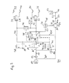
- FIG. 2 shows a circuit diagram of an electrically operated parking brake system with a relay valve.
- the circuits include 3/2-way valves as a central device. These can each be replaced by two 2/2-way valves, wherein the principles explained with reference to the 3/2-way valve are then to be transferred in the context of the present invention to the 2/2-way valve groups.
- the electrically operable parking brake system 90 is connected via a check valve 10 with a compressed air treatment system, not shown.
- the check valve 10 is followed by an optional filter unit 12, via which compressed air via an optional throttle 18 to a supply solenoid valve 14, which is designed as a 2/2-way valve, is supplied.
- a first working port 20 of a control valve device 22 is connected via a first supply line section 16.
- the line section with the filter unit 12 is referred to as the second supply line section 16 '.
- the control valve device 22 is designed as a pneumatically controllable 3/2-way valve.
- a second working connection 24 of the control valve device 22 leads via a trailer control line branch 42 to a control input 26 of a trailer control module 30. This operates a supply connection 34 and a control connection 36 of the trailer coupling.
- a control input 28 of another trailer control module 32 is connected via a further trailer control line branch 44 to the supply line branch 16. It has a supply connection 38 and a control connection 40.
- the trailer control line branches 42, 44 are connected to inputs of a select-low valve 46 whose output is connected via a control line 48 to a control input 50 of the control valve device 22.
- the select-low valve 46 operates so that at its output, that is in the control line 48, the lower input pressure is present, that is, the lower pressure from the two trailer control line branches 42, 44.
- the control line 48 is still on a relay control line 52 and a shuttle valve 54 with the relay control input 56 of the relay valve 58 in conjunction.
- the relay valve 58 receives at the supply port 92 via a relay supply line 60 compressed air from a location upstream of the supply solenoid valve 14.
- a relay output line 62 at the vent port 104 leads to line branches 64, 66, in which spring-loaded cylinders, not shown, are connected.
- a service brake line 68 is also connected. In this way, the parking brake can be automatically opened when operating the service brake to prevent overloading of the spring-loaded cylinder.
- the spring accumulator for the parking brake is combined with the control chamber for the service brake. In the park state, the spring force acts to ensure the braking effect. If at the same time the service brake is actuated in this state, an additional force is created by the controlled brake pressure, which can lead to an overload of the brake mechanism. Therefore, the service brake pressure is, for example, via the shuttle valve 54 to the relay valve 58 is controlled.
- the second elastic element 102 can contribute here to reducing the braking force loss, since the output pressure of the relay valve is influenced.
- a designed as a 2/2-way valve bleed solenoid valve 78 is provided, which is connected via the other trailer control line branch 44 to the supply line section 16.
- the bleed solenoid valve 78 has a bleed solenoid valve port 88 which opens into a vent.
- pressure sensors 80, 82 for detecting the pressures at the second working port 24 of the control valve device 22 and the
- Relay output line 62 is provided. Control chambers of the control valve device 22 are connected via a pressure equalization line 108 with a vent.
- switching state of the electrically operated parking brake system 90 are the supply solenoid valve 14, the control valve device 22, the vent solenoid valve 78 and the control and vent valve device 72 each in a first switching position.
- the second working port 24 of the control valve device 22 is vented via the control and vent valve device 72, so that in the absence of pressurization via the service brake line 68 and the control input 56 of the relay valve 58 is vented. Consequently, the spring storage cylinders, not shown, are depressurized, so that the parking brake is in its parking position.
- the relay control line 52 is thus depressurized and the spring brake cylinders, not shown, are closed.
- a control pressure for a trailer is applied to the control connection 36, while no control pressure for a trailer is present at the control connection 40.
- the control and ventilation valve device 72 is switched to the switching position, not shown. Consequently, pressure builds up in particular in the control line branch 42, the relay control line 52 and at the relay control input 56. This pressure leads to the passage of the relay valve 58 when a threshold value is exceeded, so that the spring-loaded cylinders are subjected to pressure and the parking brake is released.
- the pressure in the control line 48 is the driving force for switching the control valve 22. Depending on the switching strategy, this switching can take place before or after the control and vent valve device 72 is returned to its illustrated de-energized state.
- Another switching state of the illustrated system is present when the vent valve 78, the supply solenoid valve 14 and the control and vent valve means 72 are energized so that the control input 50 of the control valve means 22 and the control input 56 of the relay valve 58 are vented, the control input 26 of the Trailer control valve 30, however, is vented.
- These pressure conditions in the system cause a release of the trailer brake while the parking brake of the towing vehicle is inserted or remains. So there is a trailer test state, in which it can be checked whether it can be held solely by the parking brake of the towing vehicle, the entire train consisting of tractor and trailer. The changed by the second elastic element 102 characteristic of the relay valve 58 does not affect this.
- FIG. 3 shows the output pressure of a relay valve as a function of the applied control pressure for two different relay valves.
- a control pressure 110 for example in bar, which is connected to the FIG. 1 known relay control input 56 is applied.
- Plotted on the Y-axis is a venting pressure 112, also in bar, which is provided as a result of the applied control pressure at the venting port 104.
- Two horizontal rails are drawn in parallel to the X-axis and mark the necessary aeration pressure for the complete opening of a 24 "+ spring-loaded cylinder 118 or a 24" / 30 "spring-loaded cylinder 120.
- Two different pressure profiles 114, 116 are shown in the pressure diagram.
- the pressure profile 114 can be assigned to a relay valve without a second elastic element, while the pressure profile 116 can be assigned to a relay valve with a second elastic element
- the aeration pressure follows 1: 1
- the illustrated pressure curve 114 corresponds to a typical hysteresis.
- the second curve shown corresponds to the pressure curve 116 of a relay valve with a second elastic element due to the second elastic element
- the entire pressure curve with respect to the curve 114 in the diagram is shifted to the right, essentially by the additional control pressure required to overcome the preload force caused by the second elastic element.
Abstract
Description
Die Erfindung betrifft ein Relaisventil mit einem Steuerkolben und einer Manschette, die beide in einer axialen Richtung beweglich sind, wobei ein erstes elastisches Element vorgesehen ist, das die Manschette in der axialen Richtung mit einer Vorspannkraft beaufschlagtThe invention relates to a relay valve with a control piston and a sleeve, both of which are movable in an axial direction, wherein a first elastic element is provided, which acts on the sleeve in the axial direction with a biasing force
Die Erfindung betrifft weiterhin ein Verfahren zum Betreiben eines Relaisventils mit einem Steuerkolben und einer Manschette, die beide in einer axialen Richtung beweglich sind, wobei die Manschette in der axialen Richtung mit einer Vorspannkraft beaufschlagt wird.The invention further relates to a method of operating a relay valve with a control piston and a sleeve, both of which are movable in an axial direction, wherein the collar is subjected in the axial direction with a biasing force.
Die vorliegende Offenbarung befasst sich mit einem Relaisventil, insbesondere einem Relaisventil eines elektrisch betätigbaren Feststellbremssystems, wie es beispielsweise aus der
Diese zum Schutz vorgesehenen Bauteile können, insbesondere durch Vereisung oder Verschmutzung, ihre eigentliche Funktion verlieren, sodass sie an der Entlüftung einen erhöhten Staudruck verursachen. Dies ist besonders bei einem abgestellten Fahrzeug relevant, welches üblicherweise eine geschlossene Feststellbremse mit drucklosen Steuerleitungen aufweist. Weisen an die Steuerleitung angrenzende Ventile eine erhöhte Leckagerate auf, kann ein schleichender Druckaufbau in der Steuerleitung erfolgen. Auf diese Weise könnte sich in den Steuerleitungen der elektrisch betätigbaren Feststellbremse unbeabsichtigt ein großer Druck aufbauen, der zu einem ungewollten Betätigen der Feststellbremsanlage führen könnte, da der in den Steuerleitungen anstehende Druck 1:1 als Ausgangsdruck in die Federspeicher geleitet wird und diese langsam löst.These components provided for protection, in particular by icing or contamination, lose their proper function, so that they cause an increased back pressure on the vent. This is particularly relevant for a parked vehicle, which usually has a closed parking brake with pressure-free control lines. If valves adjacent to the control line have an increased leakage rate, a gradual build-up of pressure in the control line can take place. In this way, a large pressure could inadvertently build up in the control lines of the electrically actuated parking brake, which could lead to an unwanted actuation of the parking brake system, since the pending in the control lines pressure 1: 1 is passed as output pressure in the spring accumulator and this dissolves slowly.
Bei einer konventionellen pneumatischen Parkbremsanlage, tritt diese Problematik nicht auf, da die Entlüftung der Steuerleitungen der Parkbremsanlage, die im Parkzustand mit der Atmosphäre verbunden sind, über das Handbremsventil erfolgt, welches im Inneren der Fahrerkabine geschützt angeordnet ist. Ein unerwünschter Druckaufbau in den Federspeichern kann somit sicher vermieden werden.In a conventional pneumatic parking brake system, this problem does not occur because the venting of the control lines of the parking brake system, which are connected in the park state with the atmosphere, via the hand brake valve, which is arranged protected inside the cab. An undesirable buildup of pressure in the spring stores can thus be safely avoided.
Der Erfindung liegt die Aufgabe zugrunde, die oben angesprochene Problematik auch im Zusammenhang mit einer elektrisch betätigbaren Feststellbremsanlage zu lösen.The invention has for its object to solve the above-mentioned problem also in connection with an electrically actuated parking brake system.
Diese Aufgabe wird mit den Merkmalen der unabhängigen Ansprüche gelöst.This object is achieved with the features of the independent claims.
Vorteilhafte Ausführungsformen der Erfindung sind in den abhängigen Ansprüchen angegeben.Advantageous embodiments of the invention are indicated in the dependent claims.
Das erfindungsgemäße Relaisventil baut auf dem gattungsgemäßen Stand der Technik dadurch auf, dass ein zweites elastisches Element vorgesehen ist, das den Steuerkolben in der axialen Richtung mit einer weiteren Vorspannkraft beaufschlagt. Auf dieser Weise wird die Charakteristik des Relaisventils so verschoben, dass zum Aussteuern eines gewissen Ausgangsdrucks ein höherer Steuerdruck notwendig ist als ohne das zweite elastische Element notwendig wäre. Es wird daher eine höhere Robustheit gegenüber einem unerwünschten Druckanstieg in der Steuerleitung des Relaisventils, insbesondere durch Leckagen, erreicht.The relay valve according to the invention builds on the generic state of the art in that a second elastic element is provided which acts on the control piston in the axial direction with a further biasing force. In this way, the characteristic of the relay valve is shifted so that the Aussteuern a certain output pressure, a higher control pressure is necessary than would be necessary without the second elastic element. It is therefore a higher robustness against undesired pressure increase in the control line of the relay valve, in particular by leaks achieved.
Nützlicherweise kann vorgesehen sein, dass das zweite elastische Element eine Feder ist. Eine Feder ist ein vergleichsweise robustes und dennoch kostengünstig herzustellendes Bauteil, welches in einfacher Weise in das Design bestehender Relaisventils integrierbar ist, so dass keine vollständige Neukonstruktion notwendig wird.Usefully, it can be provided that the second elastic element is a spring. A spring is a comparatively robust and yet inexpensive to manufacture component, which can be easily integrated into the design of existing relay valve, so that no complete redesign is necessary.
Weiterhin kann vorgesehen sein, dass der Steuerkolben und die Manschette voneinander unabhängig bewegbar sind. Somit kann sichergestellt werden, dass das zweite elastische Element lediglich den bereitgestellten Ausgangsdruck in Abhängigkeit von dem Steuerdruck beeinflusst.Furthermore, it can be provided that the control piston and the sleeve are mutually independently movable. Thus, it can be ensured that the second elastic element only influences the provided output pressure as a function of the control pressure.
Die Erfindung betrifft weiterhin ein elektrisch betätigbares Feststellbremssystem für ein Fahrzeug, insbesondere ein Nutzfahrzeug, mit einem erfindungsgemäßen Relaisventil.The invention further relates to an electrically actuated parking brake system for a vehicle, in particular a commercial vehicle, with a relay valve according to the invention.
Die Erfindung baut auf dem gattungsgemäßen Verfahren dadurch auf, dass der Steuerkolben in der axialen Richtung mit einer weiteren Vorspannkraft beaufschlagt wird. Auf dieser Weise werden die Vorteile und Besonderheiten des erfindungsgemäßen Relaisventils auch im Rahmen eines Verfahrens umgesetzt. Dies gilt auch für die nachfolgend angegebene besonders bevorzugte Ausführungsform des erfindungsgemäßen Verfahrens.The invention is based on the generic method in that the control piston is acted upon in the axial direction with a further biasing force. In this way, the advantages and special features of the relay valve according to the invention are also implemented in the context of a method. This also applies to the particularly preferred embodiment of the method according to the invention given below.
Das erfindungsgemäße Verfahren ist vorteilhafterweise dadurch weiter gebildet, dass der Steuerkolben unabhängig von der Manschette bewegt wird.The inventive method is advantageously further formed in that the control piston is moved independently of the sleeve.
Die Erfindung wird nun mit Bezug auf die begleitenden Zeichnungen anhand besonders bevorzugter Ausführungsformen beispielhaft erläutert.The invention will now be described by way of example with reference to the accompanying drawings by way of particularly preferred embodiments.
Es zeigen:
Figur 1- ein Schnittbild eines Relaisventils;
- Figur 2
- ein Schaltungsdiagramm eines elektrisch betätigbaren Feststellbremssystems mit einem Relaisventil; und
- Figur 3
- den Ausgangsdruck eines Relaisventils in Abhängigkeit des angelegten Steuerdrucks für zwei verschiedene Relaisventile.
- FIG. 1
- a sectional view of a relay valve;
- FIG. 2
- a circuit diagram of an electrically actuated parking brake system with a relay valve; and
- FIG. 3
- the output pressure of a relay valve as a function of the applied control pressure for two different relay valves.
In den nachfolgenden Zeichnungen beschreiben gleiche Bezugzeichen gleiche oder vergleichbare Komponenten.In the following drawings, like reference numerals describe the same or similar components.
In der dargestellten Schaltposition des Relaisventils 58 liegt kein Steuerdruck an dem Relaissteuereingang 56 an, so dass der Steuerkolben 94 durch das zweite elastische Element 102 von der Manschette 96 in der axialen Richtung 98 abgehoben ist. Dabei verschließt die von dem ersten elastischen Element 100 gegen den Ventilsitz 124 gepresste Manschette 96 den Versorgungsanschluss 92, während der Belüftungsanschluss 104 mit der Entlüftung 84 verbunden ist. Dementsprechend ist, falls das dargestellte Relaisventil Bestandteil eines Feststellbremssystems ist, ein an dem Belüftungsanschluss 104 angeschlossener Feststellbremszylinder drucklos, das heißt geschlossen. Der Relaissteuereingang 56 ist in dieser Schaltstellung üblicherweise mit einer Entlüftung verbunden. Bei stärkeren Leckagen und einem erhöhten Staudruck an der Entlüftung steht dieser Staudruck im Steuerraum 126 des Relaisventils 58 an und versucht den Steuerkolben 94 zu bewegen, um den Belüftungsanschluss 104 mit dem Versorgungsanschluss 92 zu verbinden. Durch das zusätzliche zweite elastische Element 102 an dem Steuerkolben 94 muss sich ein wesentlich höherer Staudruck im Steuerraum 126 aufbauen, bevor ein Ausgangsdruck ausgesteuert wird. Das System wird daher wesentlich robuster gegen höhere Leckagen.In the illustrated switching position of the
Zum Einlegen der Parkbremse, falls das Relaisventil 58 Bestandteil eines Feststellbremssystems ist, müssen die Federspeicher entlüftet werden. Dies geschieht durch Entlüftung des Steuerraums des Relaisventils 58. Das zweite elastische Element 102 an dem Steuerkolben 94 unterstützt und beschleunigt das Abheben des Steuerkolbens 94 von der Manschette 96 und damit die Entlüftung. So wird die kritische Zeit reduziert, während der zu Entlüftung eines Feststellbremssystems die Magnetventile bestromt werden müssen und ein Stromausfall das sichere Abschließen der Funktion verhindern würde. Dies kann besonders bei Gefahrguttransportern mit einer Notfallstromabschaltung wichtig sein.To engage the parking brake, if the
Zum Lösen der Prarkbremse, falls das Relaisventil 58 Bestandteil eines Feststellbremssystems ist, müssen die Federspeicher belüftet werden. Dies geschieht durch Belüftung des Steuerraums des Relaisventils 58. Das zweite elastische Element 102 wirkt dem Steuerdruck entgegen und verzögert so ein Abheben des Steuerkolbens 94 von der Manschette 96, so dass die Belüftung verzögert wird. So wird die kritische Zeit überbrückt, während der zur Belüftung die Magnetventile der Feststellbremse bestromt werden müssen und ein Stromausfall das sichere Abschließen der Funktion verhindern würde. Dies würde dazu führen, dass ein Nutzfahrzeug mit dem vorhandenen Druck in den Federspeichern bereits bewegt werden könnte, obwohl das Hauptglied zur Sicherstellung des Fahrzustandes noch nicht in die Fahrstellung geschaltet hat.To release the parking brake, if the
Bei einer gestuften Druckabsenkung zur Bereitstellung einer die Betriebsbremse unterstützenden Bremswirkung, falls das Relaisventil 58 Bestandteil einer Feststellbremse ist, ist das Relaisventil 58 zunächst in seiner Abschlussstellung und die Feststellbremse ist geöffnet. Der Relaissteuereingang 56 wird nun stufenweise entlüftet, um eine Druckabsenkung in den Federspeicherzylindern zu erreichen. Der Belüftungsanschluss 104 wird aufgrund des zweiten elastischen Elements 102 bereits bei einer geringeren Druckdifferenz entlüftet. So kann bei gleichem Steuerdruck eine höhere Bremskraft erzielt werden. Dieser Steuerdruck liegt auch an der Steuerventileinrichtung 22 der Feststellbremse an, welche während der Hilfsbremsung über die Feststellbremse sicher in Fahrstellung bleiben muss. Dies kann bei einem höheren Druckniveau besser sichergestellt werden.In a stepped pressure reduction to provide a service brake assist braking effect, if the
Bei einem Druckaufbau an dem Relaissteuereingang 56 wird der Steuerkolben 94 entgegen der durch das zweite elastische Element 102 aufgebrachten Vorspannkraft in der axialen Richtung 98 zu der Manschette 96 hinbewegt. Durch das Anpressen des Steuerkolbens 94 auf die Manschette 96 wird, bei einem ausreichenden Steuerdruck, der Belüftungsanschluss 104 von der Entlüftung 84 getrennt, so dass nach dem Abheben der Manschette 96 von dem Ventilsitz 124 ein Druckaufbau an dem Belüftungsanschluss 104 über den dann freigegebenen Versorgungsanschluss 92 möglich ist. Die Funktion des Relaisventils 58 wird nach erfolgtem Druckaufbau nicht durch das zweite elastische Element 102 beeinflusst, da sich das Relaisventil 58 in seiner so genannten Abschlussstellung befindet.When pressure builds up on the
Relaisausgangsleitung 62 vorgesehen. Steuerräume der Steuerventileinrichtung 22 sind über eine Druckausgleichsleitung 108 mit einer Entlüftung verbunden.
Bei dem in
Ein weiterer Schaltzustand des dargestellten Systems liegt dann vor, wenn das Entlüftungsventil 78, das Versorgungsmagnetventil 14 und die Steuer- und Entlüftungsventileinrichtung 72 bestromt werden, so dass der Steuereingang 50 der Steuerventileinrichtung 22 und der Steuereingang 56 des Relaisventils 58 entlüftet werden, der Steuereingang 26 des Anhängersteuerventils 30 hingegen belüftet wird. Diese Druckverhältnisse im System bewirken ein Lösen der Anhängerbremse, während die Feststellbremse des Zugfahrzeugs eingelegt wird oder bleibt. Es liegt also ein Anhängertestzustand vor, bei dem überprüft werden kann, ob es der gesamte aus Zugfahrzeug und Anhänger bestehende Zug alleine von der Feststellbremse des Zugfahrzeugs gehalten werden kann. Die durch das zweite elastische Element 102 veränderte Charakteristik des Relaisventils 58 beeinflusst dies nicht.Another switching state of the illustrated system is present when the
Vor dem Abstellen des Fahrzeuges wird zum Schließen des Feststellbremssystems 90 die in den nicht dargestellten Federspeicherbremszylindern vorhandene Druckluft über die beiden Leitungszweige 64, 66 durch die Entlüftung 84 des Relaisventils 58 abgelassen.Before the parking of the vehicle is to close the parking brake system 90, the existing in the spring brake cylinders, not shown compressed air via the two
Dabei werden mehrere Liter Druckluft aus den Federspeicherbremszylindern und den Zuführleitungen abgelassen, so dass eventuell an der Entlüftung 84 anhaftende Verschmutzungen oder Eis, welche sich während der vorangegangen Fahrt angesammelt haben könnten, sicher entfernt werden.In this case, several liters of compressed air are discharged from the spring brake cylinders and the supply lines, so that any adhering to the vent 84 dirt or ice, which could have accumulated during the previous drive, be safely removed.
Die in der vorstehenden Beschreibung, in den Zeichnungen sowie in den Ansprüchen offenbarten Merkmale der Erfindung können sowohl einzeln als auch in beliebiger Kombination für die Verwirklichung der Erfindung wesentlich sein.The features of the invention disclosed in the foregoing description, in the drawings and in the claims may be essential to the realization of the invention both individually and in any combination.
- 1010
- Rückschlagventilcheck valve
- 1212
- Filtereinheitfilter unit
- 1414
- VersorgungsmagnetventilSupply solenoid valve
- 1616
- erster Versorgungsleitungsabschnittfirst supply line section
- 16'16 '
- zweiter Versorgungsleitungsabschnittsecond supply line section
- 1818
- Drosselthrottle
- 2020
- erster Arbeitsanschlussfirst work connection
- 2222
- SteuerventileinrichtungControl valve means
- 2424
- zweiter Arbeitsanschlusssecond work connection
- 2626
- Steuereingangcontrol input
- 2828
- Steuereingangcontrol input
- 3030
- AnhängersteuermodulTrailer control module
- 3232
- weiteres Anhängersteuermodulanother trailer control module
- 3434
- Versorgungsanschlusssupply terminal
- 3636
- Steueranschlusscontrol connection
- 3838
- Versorgungsanschlusssupply terminal
- 4040
- Steueranschlusscontrol connection
- 4242
- AnhängersteuerleitungszweigTrailer control line branch
- 4444
- weiterer Anhängersteuerleitungszweiganother trailer control line branch
- 4646
- Select-Low-VentilSelect low valve
- 4848
- Steuerleitungcontrol line
- 5050
- Steuereingangcontrol input
- 5252
- RelaissteuerleitungRelay control line
- 5454
- Wechselventilshuttle valve
- 5656
- RelaissteuereingangRelay control input
- 5858
- Relaisventilrelay valve
- 6060
- RelaisversorgungsleitungRelay supply line
- 6262
- RelaisausgangsleitungRelay output line
- 6464
- Leitungszweigleg
- 6666
- Leitungszweigleg
- 6868
- BetriebsbremsleitungOperating brake line
- 7070
- Entlüftungsanschlussexhaust port
- 7272
- Steuer- und EntlüftungsventileinrichtungControl and bleed valve device
- 7474
- zweiter Anschlusssecond connection
- 7676
- erster Anschlussfirst connection
- 7878
- EntlüftungsmagnetventilPurge solenoid valve
- 8080
- Drucksensorpressure sensor
- 8282
- Drucksensorpressure sensor
- 8484
- Entlüftungvent
- 8686
- dritter Anschlussthird connection
- 8888
- EntlüftungsmagnetventilanschlussPurge solenoid valve connection
- 9090
- elektrisch betätigbares Feststellbremssystemelectrically operated parking brake system
- 9292
- Versorgungsanschluss RelaisventilSupply connection Relay valve
- 9494
- Steuerkolbenspool
- 9696
- Manschettecuff
- 9898
- axiale Richtungaxial direction
- 100100
- erstes elastisches Elementfirst elastic element
- 102102
- zweites elastisches Elementsecond elastic element
- 104104
- Belüftungsanschlussventilation connection
- 106106
- Rückschlagventilcheck valve
- 108108
- DruckausgleichsleitungPressure equalizing line
- 110110
- Steuerdruckcontrol pressure
- 112112
- Belüftungsdruckventilation pressure
- 114114
- Druckverlauf ohne zweites elastisches ElementPressure curve without second elastic element
- 116116
- Druckverlauf mit zweitem elastischem ElementPressure curve with second elastic element
- 118118
- 24"+ Federspeicherzylinder24 "+ spring-loaded cylinder
- 120120
- 24"/30" Federspeicherzylinder24 "/ 30" spring-loaded cylinder
- 122122
- Gehäusecasing
- 124124
- Ventilsitzvalve seat
- 126126
- Steuerraum RelaisventilControl room relay valve
Claims (6)
Applications Claiming Priority (1)
| Application Number | Priority Date | Filing Date | Title |
|---|---|---|---|
| DE201010026875 DE102010026875A1 (en) | 2010-07-12 | 2010-07-12 | Relay valve and method for operating a relay valve |
Publications (2)
| Publication Number | Publication Date |
|---|---|
| EP2407355A1 true EP2407355A1 (en) | 2012-01-18 |
| EP2407355B1 EP2407355B1 (en) | 2013-05-22 |
Family
ID=44533847
Family Applications (1)
| Application Number | Title | Priority Date | Filing Date |
|---|---|---|---|
| EP20110173389 Active EP2407355B1 (en) | 2010-07-12 | 2011-07-11 | Relay valve and method for operating same |
Country Status (2)
| Country | Link |
|---|---|
| EP (1) | EP2407355B1 (en) |
| DE (1) | DE102010026875A1 (en) |
Cited By (3)
| Publication number | Priority date | Publication date | Assignee | Title |
|---|---|---|---|---|
| WO2015193102A1 (en) * | 2014-06-18 | 2015-12-23 | Knorr-Bremse Systeme für Nutzfahrzeuge GmbH | Dual-piston relay valve having an anti-compounding function |
| WO2020048706A1 (en) * | 2018-09-06 | 2020-03-12 | Knorr-Bremse Systeme für Nutzfahrzeuge GmbH | Guide sleeve for guiding a collar of a relay valve for an electropneumatic modulator |
| CN111486144A (en) * | 2019-01-29 | 2020-08-04 | 纳博特斯克有限公司 | Control valve and reversing valve |
Families Citing this family (4)
| Publication number | Priority date | Publication date | Assignee | Title |
|---|---|---|---|---|
| DE102015106150A1 (en) * | 2015-04-22 | 2016-10-27 | Knorr-Bremse Systeme für Nutzfahrzeuge GmbH | Parking brake device for motor vehicles |
| EP3118077B1 (en) | 2015-07-15 | 2021-06-16 | KNORR-BREMSE Systeme für Nutzfahrzeuge GmbH | Relay valve and method of controlling a relay valve |
| CN107472231B (en) * | 2017-09-11 | 2023-08-08 | 眉山中车制动科技股份有限公司 | Nested one-way valve structure for automatic vehicle adjusting device |
| CN113500990B (en) * | 2021-08-26 | 2022-04-08 | 山东康健汽车配件科技股份有限公司 | Electric control auxiliary braking system of relay valve |
Citations (3)
| Publication number | Priority date | Publication date | Assignee | Title |
|---|---|---|---|---|
| DE10355311A1 (en) * | 2003-09-24 | 2005-04-14 | Wabco Gmbh & Co.Ohg | Trailer control valve for traction vehicle with electronically controlled brake system |
| DE102007061908A1 (en) * | 2007-12-21 | 2009-06-25 | Knorr-Bremse Systeme für Nutzfahrzeuge GmbH | parking brake |
| WO2009098003A2 (en) * | 2008-02-06 | 2009-08-13 | Knorr-Bremse Systeme für Nutzfahrzeuge GmbH | Parking brake device |
-
2010
- 2010-07-12 DE DE201010026875 patent/DE102010026875A1/en not_active Ceased
-
2011
- 2011-07-11 EP EP20110173389 patent/EP2407355B1/en active Active
Patent Citations (4)
| Publication number | Priority date | Publication date | Assignee | Title |
|---|---|---|---|---|
| DE10355311A1 (en) * | 2003-09-24 | 2005-04-14 | Wabco Gmbh & Co.Ohg | Trailer control valve for traction vehicle with electronically controlled brake system |
| DE102007061908A1 (en) * | 2007-12-21 | 2009-06-25 | Knorr-Bremse Systeme für Nutzfahrzeuge GmbH | parking brake |
| WO2009098003A2 (en) * | 2008-02-06 | 2009-08-13 | Knorr-Bremse Systeme für Nutzfahrzeuge GmbH | Parking brake device |
| DE102008007877B3 (en) | 2008-02-06 | 2009-11-26 | Knorr-Bremse Systeme für Nutzfahrzeuge GmbH | Park brake device |
Cited By (5)
| Publication number | Priority date | Publication date | Assignee | Title |
|---|---|---|---|---|
| WO2015193102A1 (en) * | 2014-06-18 | 2015-12-23 | Knorr-Bremse Systeme für Nutzfahrzeuge GmbH | Dual-piston relay valve having an anti-compounding function |
| US10427663B2 (en) | 2014-06-18 | 2019-10-01 | Knorr-Bremse Systeme Fuer Nutzfahrzeuge Gmbh | Dual-piston relay valve having an anti-compounding function |
| WO2020048706A1 (en) * | 2018-09-06 | 2020-03-12 | Knorr-Bremse Systeme für Nutzfahrzeuge GmbH | Guide sleeve for guiding a collar of a relay valve for an electropneumatic modulator |
| US11738731B2 (en) | 2018-09-06 | 2023-08-29 | Knorr-Bremse Systeme Fuer Nutzfahrzeuge Gmbh | Guide sleeve for guiding a collar of a relay valve for an electropneumatic modulator |
| CN111486144A (en) * | 2019-01-29 | 2020-08-04 | 纳博特斯克有限公司 | Control valve and reversing valve |
Also Published As
| Publication number | Publication date |
|---|---|
| DE102010026875A1 (en) | 2012-01-12 |
| EP2407355B1 (en) | 2013-05-22 |
Similar Documents
| Publication | Publication Date | Title |
|---|---|---|
| EP2576301B1 (en) | Electrically actuable parking brake system and method for operating an electrically actuable parking brake system | |
| EP2384943B1 (en) | Valve device, electrically actuated handbrake and method for controlling same | |
| EP3112230B1 (en) | Parking brake module, brake system and vehicle using same and method for operating a parking brake having such a module | |
| EP2407355B1 (en) | Relay valve and method for operating same | |
| EP2547565B1 (en) | Electrically actuatable parking brake system | |
| DE102015114176C5 (en) | Electric parking brake device with additional energy supply | |
| EP2338753B1 (en) | Electrically actuated handbrake and method for controlling same | |
| EP2133250B1 (en) | Park brake valve assembly for a braking system of a commercial vehicle | |
| DE102011107155B4 (en) | Compressed air treatment plant and method for operating a compressed air treatment plant | |
| EP3515771B1 (en) | Parking brake device for a utility vehicle | |
| EP2675673B1 (en) | Compressed air supply for commerciual vehicle | |
| EP2298616A2 (en) | Control device and method for testing a valve device of an electric parking brake | |
| WO2014170299A2 (en) | Pneumatic system | |
| EP2338754B1 (en) | Electrically actuated handbrake and method for controlling same | |
| EP2675674B1 (en) | Compressed air supply device for commercial vehicles | |
| DE102015106146A1 (en) | Parking brake device for motor vehicles | |
| DE102008033696B4 (en) | Multi-circuit protection valve for a compressed air supply system | |
| EP2094547B1 (en) | Parking brake device comprising compressed air supply lines for a parking brake | |
| WO2012110547A1 (en) | Multi-circuit protection valve for a compressed-air supply device of a vehicle, and method for operating a multi-circuit protection valve | |
| EP2384944B1 (en) | Method for operating an electrically actuated handbrake | |
| EP2371644B1 (en) | Pressurised air assembly | |
| DE102018002488A1 (en) | Braking system of a vehicle train | |
| EP2883768A1 (en) | Coupling head unit for a commercial vehicle and method for coupling a supply line and a control line to a pneumatically operated brake system |
Legal Events
| Date | Code | Title | Description |
|---|---|---|---|
| AK | Designated contracting states |
Kind code of ref document: A1 Designated state(s): AL AT BE BG CH CY CZ DE DK EE ES FI FR GB GR HR HU IE IS IT LI LT LU LV MC MK MT NL NO PL PT RO RS SE SI SK SM TR |
|
| AX | Request for extension of the european patent |
Extension state: BA ME |
|
| PUAI | Public reference made under article 153(3) epc to a published international application that has entered the european phase |
Free format text: ORIGINAL CODE: 0009012 |
|
| 17P | Request for examination filed |
Effective date: 20120718 |
|
| GRAP | Despatch of communication of intention to grant a patent |
Free format text: ORIGINAL CODE: EPIDOSNIGR1 |
|
| RIC1 | Information provided on ipc code assigned before grant |
Ipc: B60T 13/38 20060101ALI20121105BHEP Ipc: B60T 7/20 20060101AFI20121105BHEP Ipc: B60T 15/20 20060101ALI20121105BHEP Ipc: B60T 13/68 20060101ALI20121105BHEP Ipc: B60T 15/18 20060101ALI20121105BHEP Ipc: B60T 11/10 20060101ALI20121105BHEP Ipc: B60T 17/18 20060101ALI20121105BHEP |
|
| RIN1 | Information on inventor provided before grant (corrected) |
Inventor name: MANN, DANIEL Inventor name: KAUPERT, OLIVER Inventor name: BALOGH, LEVENTE |
|
| GRAS | Grant fee paid |
Free format text: ORIGINAL CODE: EPIDOSNIGR3 |
|
| GRAA | (expected) grant |
Free format text: ORIGINAL CODE: 0009210 |
|
| AK | Designated contracting states |
Kind code of ref document: B1 Designated state(s): AL AT BE BG CH CY CZ DE DK EE ES FI FR GB GR HR HU IE IS IT LI LT LU LV MC MK MT NL NO PL PT RO RS SE SI SK SM TR |
|
| REG | Reference to a national code |
Ref country code: GB Ref legal event code: FG4D Free format text: NOT ENGLISH |
|
| REG | Reference to a national code |
Ref country code: CH Ref legal event code: EP |
|
| REG | Reference to a national code |
Ref country code: AT Ref legal event code: REF Ref document number: 613050 Country of ref document: AT Kind code of ref document: T Effective date: 20130615 |
|
| REG | Reference to a national code |
Ref country code: IE Ref legal event code: FG4D Free format text: LANGUAGE OF EP DOCUMENT: GERMAN |
|
| REG | Reference to a national code |
Ref country code: DE Ref legal event code: R096 Ref document number: 502011000765 Country of ref document: DE Effective date: 20130718 |
|
| REG | Reference to a national code |
Ref country code: SE Ref legal event code: TRGR |
|
| REG | Reference to a national code |
Ref country code: NL Ref legal event code: T3 |
|
| REG | Reference to a national code |
Ref country code: LT Ref legal event code: MG4D |
|
| PG25 | Lapsed in a contracting state [announced via postgrant information from national office to epo] |
Ref country code: PT Free format text: LAPSE BECAUSE OF FAILURE TO SUBMIT A TRANSLATION OF THE DESCRIPTION OR TO PAY THE FEE WITHIN THE PRESCRIBED TIME-LIMIT Effective date: 20130923 Ref country code: NO Free format text: LAPSE BECAUSE OF FAILURE TO SUBMIT A TRANSLATION OF THE DESCRIPTION OR TO PAY THE FEE WITHIN THE PRESCRIBED TIME-LIMIT Effective date: 20130822 Ref country code: SI Free format text: LAPSE BECAUSE OF FAILURE TO SUBMIT A TRANSLATION OF THE DESCRIPTION OR TO PAY THE FEE WITHIN THE PRESCRIBED TIME-LIMIT Effective date: 20130522 Ref country code: LT Free format text: LAPSE BECAUSE OF FAILURE TO SUBMIT A TRANSLATION OF THE DESCRIPTION OR TO PAY THE FEE WITHIN THE PRESCRIBED TIME-LIMIT Effective date: 20130522 Ref country code: ES Free format text: LAPSE BECAUSE OF FAILURE TO SUBMIT A TRANSLATION OF THE DESCRIPTION OR TO PAY THE FEE WITHIN THE PRESCRIBED TIME-LIMIT Effective date: 20130902 Ref country code: FI Free format text: LAPSE BECAUSE OF FAILURE TO SUBMIT A TRANSLATION OF THE DESCRIPTION OR TO PAY THE FEE WITHIN THE PRESCRIBED TIME-LIMIT Effective date: 20130522 Ref country code: GR Free format text: LAPSE BECAUSE OF FAILURE TO SUBMIT A TRANSLATION OF THE DESCRIPTION OR TO PAY THE FEE WITHIN THE PRESCRIBED TIME-LIMIT Effective date: 20130823 |
|
| PG25 | Lapsed in a contracting state [announced via postgrant information from national office to epo] |
Ref country code: RS Free format text: LAPSE BECAUSE OF FAILURE TO SUBMIT A TRANSLATION OF THE DESCRIPTION OR TO PAY THE FEE WITHIN THE PRESCRIBED TIME-LIMIT Effective date: 20130522 Ref country code: PL Free format text: LAPSE BECAUSE OF FAILURE TO SUBMIT A TRANSLATION OF THE DESCRIPTION OR TO PAY THE FEE WITHIN THE PRESCRIBED TIME-LIMIT Effective date: 20130522 Ref country code: HR Free format text: LAPSE BECAUSE OF FAILURE TO SUBMIT A TRANSLATION OF THE DESCRIPTION OR TO PAY THE FEE WITHIN THE PRESCRIBED TIME-LIMIT Effective date: 20130522 Ref country code: BG Free format text: LAPSE BECAUSE OF FAILURE TO SUBMIT A TRANSLATION OF THE DESCRIPTION OR TO PAY THE FEE WITHIN THE PRESCRIBED TIME-LIMIT Effective date: 20130822 |
|
| PG25 | Lapsed in a contracting state [announced via postgrant information from national office to epo] |
Ref country code: LV Free format text: LAPSE BECAUSE OF FAILURE TO SUBMIT A TRANSLATION OF THE DESCRIPTION OR TO PAY THE FEE WITHIN THE PRESCRIBED TIME-LIMIT Effective date: 20130522 |
|
| BERE | Be: lapsed |
Owner name: KNORR-BREMSE SYSTEME FUR NUTZFAHRZEUGE G.M.B.H. Effective date: 20130731 |
|
| PG25 | Lapsed in a contracting state [announced via postgrant information from national office to epo] |
Ref country code: SK Free format text: LAPSE BECAUSE OF FAILURE TO SUBMIT A TRANSLATION OF THE DESCRIPTION OR TO PAY THE FEE WITHIN THE PRESCRIBED TIME-LIMIT Effective date: 20130522 Ref country code: EE Free format text: LAPSE BECAUSE OF FAILURE TO SUBMIT A TRANSLATION OF THE DESCRIPTION OR TO PAY THE FEE WITHIN THE PRESCRIBED TIME-LIMIT Effective date: 20130522 Ref country code: DK Free format text: LAPSE BECAUSE OF FAILURE TO SUBMIT A TRANSLATION OF THE DESCRIPTION OR TO PAY THE FEE WITHIN THE PRESCRIBED TIME-LIMIT Effective date: 20130522 Ref country code: CZ Free format text: LAPSE BECAUSE OF FAILURE TO SUBMIT A TRANSLATION OF THE DESCRIPTION OR TO PAY THE FEE WITHIN THE PRESCRIBED TIME-LIMIT Effective date: 20130522 |
|
| PG25 | Lapsed in a contracting state [announced via postgrant information from national office to epo] |
Ref country code: MC Free format text: LAPSE BECAUSE OF FAILURE TO SUBMIT A TRANSLATION OF THE DESCRIPTION OR TO PAY THE FEE WITHIN THE PRESCRIBED TIME-LIMIT Effective date: 20130522 Ref country code: RO Free format text: LAPSE BECAUSE OF FAILURE TO SUBMIT A TRANSLATION OF THE DESCRIPTION OR TO PAY THE FEE WITHIN THE PRESCRIBED TIME-LIMIT Effective date: 20130522 |
|
| PLBE | No opposition filed within time limit |
Free format text: ORIGINAL CODE: 0009261 |
|
| STAA | Information on the status of an ep patent application or granted ep patent |
Free format text: STATUS: NO OPPOSITION FILED WITHIN TIME LIMIT |
|
| REG | Reference to a national code |
Ref country code: IE Ref legal event code: MM4A |
|
| 26N | No opposition filed |
Effective date: 20140225 |
|
| PG25 | Lapsed in a contracting state [announced via postgrant information from national office to epo] |
Ref country code: BE Free format text: LAPSE BECAUSE OF NON-PAYMENT OF DUE FEES Effective date: 20130731 |
|
| REG | Reference to a national code |
Ref country code: DE Ref legal event code: R097 Ref document number: 502011000765 Country of ref document: DE Effective date: 20140225 |
|
| PG25 | Lapsed in a contracting state [announced via postgrant information from national office to epo] |
Ref country code: IE Free format text: LAPSE BECAUSE OF NON-PAYMENT OF DUE FEES Effective date: 20130711 |
|
| REG | Reference to a national code |
Ref country code: CH Ref legal event code: PL |
|
| PG25 | Lapsed in a contracting state [announced via postgrant information from national office to epo] |
Ref country code: CH Free format text: LAPSE BECAUSE OF NON-PAYMENT OF DUE FEES Effective date: 20140731 Ref country code: LI Free format text: LAPSE BECAUSE OF NON-PAYMENT OF DUE FEES Effective date: 20140731 |
|
| PG25 | Lapsed in a contracting state [announced via postgrant information from national office to epo] |
Ref country code: SM Free format text: LAPSE BECAUSE OF FAILURE TO SUBMIT A TRANSLATION OF THE DESCRIPTION OR TO PAY THE FEE WITHIN THE PRESCRIBED TIME-LIMIT Effective date: 20130522 |
|
| PG25 | Lapsed in a contracting state [announced via postgrant information from national office to epo] |
Ref country code: MT Free format text: LAPSE BECAUSE OF FAILURE TO SUBMIT A TRANSLATION OF THE DESCRIPTION OR TO PAY THE FEE WITHIN THE PRESCRIBED TIME-LIMIT Effective date: 20130522 Ref country code: CY Free format text: LAPSE BECAUSE OF FAILURE TO SUBMIT A TRANSLATION OF THE DESCRIPTION OR TO PAY THE FEE WITHIN THE PRESCRIBED TIME-LIMIT Effective date: 20130522 |
|
| PG25 | Lapsed in a contracting state [announced via postgrant information from national office to epo] |
Ref country code: HU Free format text: LAPSE BECAUSE OF FAILURE TO SUBMIT A TRANSLATION OF THE DESCRIPTION OR TO PAY THE FEE WITHIN THE PRESCRIBED TIME-LIMIT; INVALID AB INITIO Effective date: 20110711 Ref country code: MK Free format text: LAPSE BECAUSE OF FAILURE TO SUBMIT A TRANSLATION OF THE DESCRIPTION OR TO PAY THE FEE WITHIN THE PRESCRIBED TIME-LIMIT Effective date: 20130522 Ref country code: LU Free format text: LAPSE BECAUSE OF NON-PAYMENT OF DUE FEES Effective date: 20130711 |
|
| PG25 | Lapsed in a contracting state [announced via postgrant information from national office to epo] |
Ref country code: IS Free format text: LAPSE BECAUSE OF FAILURE TO SUBMIT A TRANSLATION OF THE DESCRIPTION OR TO PAY THE FEE WITHIN THE PRESCRIBED TIME-LIMIT Effective date: 20130522 |
|
| REG | Reference to a national code |
Ref country code: FR Ref legal event code: PLFP Year of fee payment: 6 |
|
| REG | Reference to a national code |
Ref country code: FR Ref legal event code: PLFP Year of fee payment: 7 |
|
| REG | Reference to a national code |
Ref country code: AT Ref legal event code: MM01 Ref document number: 613050 Country of ref document: AT Kind code of ref document: T Effective date: 20160711 |
|
| PG25 | Lapsed in a contracting state [announced via postgrant information from national office to epo] |
Ref country code: AT Free format text: LAPSE BECAUSE OF NON-PAYMENT OF DUE FEES Effective date: 20160711 |
|
| REG | Reference to a national code |
Ref country code: FR Ref legal event code: PLFP Year of fee payment: 8 |
|
| PG25 | Lapsed in a contracting state [announced via postgrant information from national office to epo] |
Ref country code: AL Free format text: LAPSE BECAUSE OF FAILURE TO SUBMIT A TRANSLATION OF THE DESCRIPTION OR TO PAY THE FEE WITHIN THE PRESCRIBED TIME-LIMIT Effective date: 20130522 |
|
| PGFP | Annual fee paid to national office [announced via postgrant information from national office to epo] |
Ref country code: NL Payment date: 20200729 Year of fee payment: 10 |
|
| PGFP | Annual fee paid to national office [announced via postgrant information from national office to epo] |
Ref country code: TR Payment date: 20200710 Year of fee payment: 10 |
|
| PGFP | Annual fee paid to national office [announced via postgrant information from national office to epo] |
Ref country code: IT Payment date: 20200731 Year of fee payment: 10 |
|
| PGFP | Annual fee paid to national office [announced via postgrant information from national office to epo] |
Ref country code: FR Payment date: 20210721 Year of fee payment: 11 |
|
| REG | Reference to a national code |
Ref country code: NL Ref legal event code: MM Effective date: 20210801 |
|
| PG25 | Lapsed in a contracting state [announced via postgrant information from national office to epo] |
Ref country code: NL Free format text: LAPSE BECAUSE OF NON-PAYMENT OF DUE FEES Effective date: 20210801 |
|
| PG25 | Lapsed in a contracting state [announced via postgrant information from national office to epo] |
Ref country code: TR Free format text: LAPSE BECAUSE OF NON-PAYMENT OF DUE FEES Effective date: 20210711 |
|
| PG25 | Lapsed in a contracting state [announced via postgrant information from national office to epo] |
Ref country code: IT Free format text: LAPSE BECAUSE OF NON-PAYMENT OF DUE FEES Effective date: 20210711 |
|
| PGFP | Annual fee paid to national office [announced via postgrant information from national office to epo] |
Ref country code: SE Payment date: 20220721 Year of fee payment: 12 Ref country code: GB Payment date: 20220725 Year of fee payment: 12 |
|
| PG25 | Lapsed in a contracting state [announced via postgrant information from national office to epo] |
Ref country code: FR Free format text: LAPSE BECAUSE OF NON-PAYMENT OF DUE FEES Effective date: 20220731 |
|
| P01 | Opt-out of the competence of the unified patent court (upc) registered |
Effective date: 20230607 |
|
| PGFP | Annual fee paid to national office [announced via postgrant information from national office to epo] |
Ref country code: DE Payment date: 20230720 Year of fee payment: 13 |
|
| REG | Reference to a national code |
Ref country code: SE Ref legal event code: EUG |
|
| GBPC | Gb: european patent ceased through non-payment of renewal fee |
Effective date: 20230711 |