EP2407311A1 - Printer device - Google Patents
Printer device Download PDFInfo
- Publication number
- EP2407311A1 EP2407311A1 EP09841492A EP09841492A EP2407311A1 EP 2407311 A1 EP2407311 A1 EP 2407311A1 EP 09841492 A EP09841492 A EP 09841492A EP 09841492 A EP09841492 A EP 09841492A EP 2407311 A1 EP2407311 A1 EP 2407311A1
- Authority
- EP
- European Patent Office
- Prior art keywords
- medium
- plate
- printing
- feeding
- support
- Prior art date
- Legal status (The legal status is an assumption and is not a legal conclusion. Google has not performed a legal analysis and makes no representation as to the accuracy of the status listed.)
- Granted
Links
- 238000011144 upstream manufacturing Methods 0.000 claims description 23
- 239000000463 material Substances 0.000 description 6
- 239000002184 metal Substances 0.000 description 4
- 239000007769 metal material Substances 0.000 description 3
- 238000003825 pressing Methods 0.000 description 3
- 230000006837 decompression Effects 0.000 description 2
- 230000000694 effects Effects 0.000 description 2
- 238000004519 manufacturing process Methods 0.000 description 2
- 230000002093 peripheral effect Effects 0.000 description 2
- 125000006850 spacer group Chemical group 0.000 description 2
- 229910001220 stainless steel Inorganic materials 0.000 description 2
- 239000010935 stainless steel Substances 0.000 description 2
- 238000003860 storage Methods 0.000 description 2
- 238000005520 cutting process Methods 0.000 description 1
- 230000005484 gravity Effects 0.000 description 1
- 230000001678 irradiating effect Effects 0.000 description 1
- 238000000034 method Methods 0.000 description 1
- 239000002904 solvent Substances 0.000 description 1
- XLYOFNOQVPJJNP-UHFFFAOYSA-N water Substances O XLYOFNOQVPJJNP-UHFFFAOYSA-N 0.000 description 1
Images



Classifications
-
- B—PERFORMING OPERATIONS; TRANSPORTING
- B41—PRINTING; LINING MACHINES; TYPEWRITERS; STAMPS
- B41J—TYPEWRITERS; SELECTIVE PRINTING MECHANISMS, i.e. MECHANISMS PRINTING OTHERWISE THAN FROM A FORME; CORRECTION OF TYPOGRAPHICAL ERRORS
- B41J11/00—Devices or arrangements of selective printing mechanisms, e.g. ink-jet printers or thermal printers, for supporting or handling copy material in sheet or web form
- B41J11/02—Platens
-
- B—PERFORMING OPERATIONS; TRANSPORTING
- B41—PRINTING; LINING MACHINES; TYPEWRITERS; STAMPS
- B41J—TYPEWRITERS; SELECTIVE PRINTING MECHANISMS, i.e. MECHANISMS PRINTING OTHERWISE THAN FROM A FORME; CORRECTION OF TYPOGRAPHICAL ERRORS
- B41J11/00—Devices or arrangements of selective printing mechanisms, e.g. ink-jet printers or thermal printers, for supporting or handling copy material in sheet or web form
- B41J11/001—Handling wide copy materials
-
- B—PERFORMING OPERATIONS; TRANSPORTING
- B41—PRINTING; LINING MACHINES; TYPEWRITERS; STAMPS
- B41J—TYPEWRITERS; SELECTIVE PRINTING MECHANISMS, i.e. MECHANISMS PRINTING OTHERWISE THAN FROM A FORME; CORRECTION OF TYPOGRAPHICAL ERRORS
- B41J11/00—Devices or arrangements of selective printing mechanisms, e.g. ink-jet printers or thermal printers, for supporting or handling copy material in sheet or web form
-
- B—PERFORMING OPERATIONS; TRANSPORTING
- B41—PRINTING; LINING MACHINES; TYPEWRITERS; STAMPS
- B41J—TYPEWRITERS; SELECTIVE PRINTING MECHANISMS, i.e. MECHANISMS PRINTING OTHERWISE THAN FROM A FORME; CORRECTION OF TYPOGRAPHICAL ERRORS
- B41J11/00—Devices or arrangements of selective printing mechanisms, e.g. ink-jet printers or thermal printers, for supporting or handling copy material in sheet or web form
- B41J11/02—Platens
- B41J11/06—Flat page-size platens or smaller flat platens having a greater size than line-size platens
Definitions
- the present invention relates to a printer apparatus in which ink is ejected from a printer head to perform printing on a printing medium and, more specifically, relates to a printer apparatus which is capable of printing on a plate-like printing medium.
- a printer apparatus in which control for feeding a printing medium formed of a sheet-like material (hereinafter, referred to as a sheet-like medium) in a front and rear direction with respect to a platen and control for ejecting ink while moving a printer head facing the platen in a right and left direction are performed in a combined manner to perform printing on the printing medium.
- a printing medium formed of a plate-like material hereinafter, referred to as a plate-like medium
- a plate-like medium has been required to be printed by the printer apparatus.
- a structure in which a support member for horizontally supporting a plate-like medium is provided on a front side and a rear side of the platen. According to this structure, a plate-like medium is fed in the front and rear direction while being horizontally supported and printing can be performed on the plate-like medium.
- a structure in which a first support arm 101 and a second support arm 103 are provided on a front side and a rear side of a platen 10 to support a plate-like medium 20 horizontally and the plate-like medium 20 is moved in the front and rear direction by means of rotating a feed roller 15 is rotated.
- the plate-like medium 20 is moved in the front and rear direction while an under face of the plate-like medium 20 is slid on an upper face of the platen 10 by the rotated feed roller 15.
- a large-scale plate-like medium (for example, whose width in the right and left direction is about 1m and whose length in the front and rear direction is about 1.6m) is required to be printed.
- a large-scale plate-like medium for example, whose width in the right and left direction is about 1m and whose length in the front and rear direction is about 1.6m.
- an objective of the present invention is to provide a printer apparatus in which a plate-like medium is fed in the front and rear direction with a high degree of accuracy and, as a result, printing quality is improved.
- the present invention provides a printer apparatus in which ink is ejected to perform printing on a printing medium (for example, a sheet-like medium "S" or a plate-like medium “B” in the embodiment) while a printer head facing the printing medium is relatively moved in a feeding direction and a scanning direction perpendicular to each other with respect to the printing medium that is supported by a medium support means (for example, the platen 13 in the embodiment) for supporting the printing medium, the printer apparatus including:
- the feeding auxiliary member is provided with a support shaft (for example, the shaft member 42 in the embodiment) and a rotation member (for example, the support roller 41 in the embodiment) which is rotationally attached to the support shaft, and the feeding auxiliary member is attached to the medium support means so that the support shaft is directed in the scanning direction, and an upper part of the rotation member is protruded on an upper side with respect to the support face.
- a support shaft for example, the shaft member 42 in the embodiment
- a rotation member for example, the support roller 41 in the embodiment
- a plate-like printing medium for example, the plate-like medium "B" in the embodiment
- the plate-like printing medium being extended longer in the feeding direction than a length in the feeding direction of the medium support means and, when printing is to be performed while the plate-like printing medium is supported and fed in the feeding direction
- an upstream side support base for example, the rear side support base 60 in the embodiment
- the upstream side support base being detachably attached to the printer apparatus for supporting an unprinted portion of the plate-like printing medium
- a downstream side support base for example, the front side support base 70 in the embodiment
- the downstream side support base being detachably attached to the printer apparatus for supporting a portion having been printed of the plate-like printing medium
- the plate-like printing medium is supported by the upstream side support base and the downstream side support base and
- each of the upstream side support base and the downstream side support base is structured of a medium support rail (for example, the feeding rail 61 and the feeding rail 71 in the embodiment), which supports the plate-like printing medium, and a rail support leg (for example, the support leg 63 in the embodiment) which is extended to a lower side with respect to the medium support rail for supporting the medium support rail, an upstream side in the feeding direction of the medium support rail is located on an upper side or in a substantially horizontal state with respect to a downstream side in the feeding direction by means of adjusting an inclination angle of the medium support rail with respect to the rail support leg, and a vertically positional relationship between an end part on the downstream side in the feeding direction of the upstream side support base and the pinching rollers is adjustable, and a vertically positional relationship between an end part on the upstream side in the feeding direction of the downstream side support base and the medium support means is adjustable.
- a medium support rail for example, the feeding rail 61 and the feeding rail 71 in the embodiment
- a rail support leg for
- the printer apparatus in accordance with the present invention is structured so that the medium support means is provided with the feeding auxiliary member, which is protruded with respect to the support face, on a downstream side in the feeding direction with respect to a portion facing the printer head.
- the printing medium is fed in a supported state by the pinching rollers and the feeding auxiliary member and thus the printing medium and the medium support means can be prevented from directly contacting with each other.
- the feeding auxiliary member is provided with a support shaft and a rotation member which is rotationally attached to the support shaft and the upper part of the rotation member is protruded to an upper side with respect to the support face of the medium support means.
- an upstream side support base and a downstream side support base are provided for supporting the plate-like printing medium.
- the plate-like printing medium can be fed on the medium support means so as to be substantially horizontal state and the plate-like printing medium is supported by the pinching roller and the feeding auxiliary member and can be fed in a separated state from the support face on the medium support means. Therefore, sliding resistance occurring between the plate-like printing medium and the medium support means is reduced and thus the plate-like printing medium can be fed with a small force.
- each of the upstream side support base and the downstream side support base is structured of a medium support rail which supports the plate-like printing medium, and a rail support leg for supporting the medium support rail, and an inclination angle of the medium support rail with respect to the rail support leg is adjustable.
- an inclination angle of the medium support rail of each of the upstream side support base and the downstream side support base is set so that, for example, its upstream side in the feeding direction is a little higher, the plate-like printing medium is fed from a higher position to a lower position as a whole at the time of feeding in the feeding direction. Therefore, the plate-like printing medium can be fed in the feeding direction smoothly without operating against the gravity.
- a structure of a printer apparatus 10 to which the present invention is applied will be described below with reference to Figs. 1 through 6 .
- the printer apparatus 10 is originally structured as shown in Fig. 1 and printing can be performed on a sheet-like medium "S" by using this structure.
- a rear side support base 60 and a front side support base 70 which will be described below are attached to the printer apparatus 10.
- the printer apparatus 10 is capable of printing for both of a sheet-like medium "S" and a plate-like medium.
- a structure will be described in which printing is performed by using an ultraviolet curing type ink (hereinafter, referred to as "UV" ink) which is cured by irradiation of ultraviolet rays.
- UV ink ultraviolet curing type ink
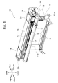
- the printer apparatus 10 is, as shown in Fig. 1 , structured of a support leg 11 having right and left support legs 11a and 11b, a center body part 12 supported by the support leg 11, a left body part 14 provided on a left side of the center body part 12, a right body part 15 provided on a right side of the center body part 12, and an upper body part 16 which connects the right and left body parts 14 and 15 with each other and is extended on an upper side of the center body part 12 in a separated and parallel manner.
- the center body part 12 is provided with a flat plate-shaped platen 13 which is exposed on its upper face and extended in the right and left direction.
- An operation part 18 which is structured of operation switches, display devices and the like is provided on a front face side at a left end part of the center body part 12.
- the left end part of the center body part 12 is incorporated with a controller 19.
- the controller 19 outputs operation signals to respective structure parts of the printer apparatus 10 which will be described below to drive and control the respective structure parts.
- the controller 19 drives and controls a vertically moving mechanism (not shown), a front and rear drive motor 25, printer heads 32, a right ultraviolet ray irradiation device 33R, a left ultraviolet ray irradiation device 33L, and a right and left drive motor 39, and the like which will be described below.
- a guide rail 17 extended in the right and left direction is provided on a front face side at a lower part of the upper body part 16.
- a printing unit 30 is attached to the guide rail 17 so as to be movable in the right and left direction.
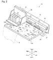
- the printing unit 30 is, as shown in Fig. 2 , mainly structured of a carriage 31, the printer heads 32, the right ultraviolet ray irradiation device 33R and the left ultraviolet ray irradiation device 33L.
- the printing unit 30 is, for example, provided with a vertically moving mechanism (not shown) for moving the printing unit 30 in an upper and lower direction with respect to the guide rail 17 depending on a thickness of a printing medium (sheet-like medium "S" or plate-like medium "B”) to be printed. Therefore, a distance between the printer heads 32 and a printing medium can be set in a predetermined distance which is suitable for printing by the vertically moving mechanism regardless of the thickness of a printing medium that is to be used.
- a mechanism for moving the printing unit 30 along the guide rail 17 reciprocatedly in the right and left direction for example, a mechanism may be utilized in which the carriage 31 and a right and left carrying belt (not shown) which is arranged on an inside of the upper body part 16 so as to be extended in the right and left direction are connected with each other and the right and left carrying belt is driven by the right and left drive motor 39 (see Fig. 1 ) which is provided in the right body part 15.
- a rear face side of the carriage 31 is fitted to the guide rail 17 so that the carriage 31 is reciprocatedly movable along the guide rail 17 in the right and left direction. Further, the carriage 31 is a mounting base for the printer heads 32, the right ultraviolet ray irradiation device 33R and the left ultraviolet ray irradiation device 33L.
- the printer heads 32 are, for example, structured of a "Magenta” head, a "Yellow” head, a "Cyan” head and a "Black” head.
- An under face of each of the printer heads 32 is formed with a plurality of ejection nozzles (not shown) for ejecting "UV" ink toward a lower side.
- the right ultraviolet ray irradiation device 33R is adjacently mounted on the right side of the printer heads 32.
- the right ultraviolet ray irradiation device 33R is mounted with a light source such as an LED in its inside for irradiating ultraviolet rays. Ultraviolet rays are irradiated from the light source toward the lower side.
- the left ultraviolet ray irradiation device 33L is provided with the same structure as the right ultraviolet ray irradiation device 33R and is adjacently mounted on the left side of the printer heads 32.
- the "UV" ink which is ejected from the printer head 32 and adhered to a printing medium is surely cured by ultraviolet rays irradiated from the right ultraviolet ray irradiation device 33R and the left ultraviolet ray irradiation device 33L.
- a plurality of clamp devices 23 is attached to a lower part of the upper body part 16 side by side in the right and left direction.
- a pinch roller 24 is rotationally attached to a tip end part on the front side of the clamp device 23.
- a lower side of the pinch roller 24 is disposed with a feed roller 21 formed in a cylindrical tube shape and extended in the right and left direction so as to protrude with respect to the upper face of the platen 13 (see Figs. 7 and 8 ).
- the feed roller 21 is rotationally driven, for example, by the front and rear drive motor 25 provided in the inside of the center body part 12.
- the clamp device 23 is capable of being set at a clamp position where the pinch roller 24 is pressed against the feed roller 21 and at an unclamp position where the pinch roller 24 is separated from the feed roller 21. According to this structure, in a state that the clamp device 23 is set at a clamp position so that a printing medium is pinched between the pinch roller 24 and the feed roller 21, when the feed roller 21 is rotated, the printing medium is fed to the front side or rear side by a predetermined distance. An abutting portion of a surface of the feed roller 21 with the pinch roller 24 is, for example, stuck and fixed with a metal mesh member 22. According to this structure, contact resistance of the feed roller 21 with the printing medium is increased and thus the printing medium can be fed to the front side and the rear side with a high degree of accuracy without occurring a slip.
- a plurality of suction holes 13a is formed in the platen 13 and an under face of the platen 13 is provided with a decompression chamber (not shown) which is in communication with the suction holes 13a.
- a decompression chamber (not shown) which is in communication with the suction holes 13a.
- a plurality of feeding auxiliary members 40 is provided in the platen 13 for feeding the plate-like medium "B" in the front and rear direction with a high degree of accuracy. Structure of the feeding auxiliary member 40 will be described below with further reference to Figs. 3 and 4 .
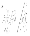
- FIG. 3 A portion surrounded by two-dot chain line in Fig. 3 is an exploded perspective view showing the feeding auxiliary member 40.
- the feeding auxiliary member 40 is structured of a support roller 41, a shaft member 42, two washers 43 and two pressing metal fittings 44.
- the support roller 41 is formed in a ring shape, for example, by using metal material. Further, a bearing, for example, whose outer peripheral diameter is about 7mm and inner peripheral diameter is about 3mm may be used as the support roller 41.
- the shaft member 42 is a shaft which is, for example, formed of metal material and the shaft member 42 is inserted into a center opening part of the support roller 41 in the right and left direction.
- the washer 43 is formed in a ring shape, for example, by using metal material. Further, the shaft member 42 is inserted into a center opening part of the washer 43 and two washers 43 are located separately on the right and left sides of the support roller 41. In a state that the shaft member 42 is inserted into the support roller 41 and the washers 43, the support roller 41 and the washers 43 are rotatable with respect to the shaft member 42.
- the pressing metal fitting 44 is formed in a plate shape, for example, by using SUS (stainless steel) whose thickness is about 0.15-0.20mm.
- Fig. 4 is a cross-sectional view showing a state where the feeding auxiliary member 40 is fixed to the platen 13.
- the shaft member 42 is pressed and fixed to the platen 13 by the pressing metal fittings 44 and the support roller 41 is rotatable with respect to the fixed shaft member 42. In this fixed state, an upper end part of the support roller 41 is protruded about 0.1mm from the upper face of the platen 13.
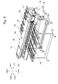
- a rear side support base 60 is provided on a rear side of the printer apparatus 10 and a front side support base 70 is provided on its front side in order to support the plate-like medium "B" in a substantially horizontal state (see Figs. 5 and 6 ).
- a structure of the rear side support base 60 will be described below with further reference to Fig. 6 .
- the structure of the front side support base 70 is the same as that of the rear side support base 60 and thus its description is omitted.
- the rear side support base 60 is structured so that a feeding rail 61 whose length in the front and rear direction is about 1.2m and on which a plurality of carrying rollers 62 is adjacently disposed in the front and rear direction is swingably supported by support legs 63.
- An inclination adjusting plate 64 is attached so as to connect the feeding rail 61 with the support leg 63 and the inclination adjusting plate 64 is swingably attached to the support leg 63.
- the inclination adjusting plate 64 is formed with an elongated hole 65.
- the feeding rail 61 may be fixed in a substantially horizontal state or, as shown in Fig. 9 , the feeding rail 61 may be inclined downward to be folded.
- the rear side support base 60 When the rear side support base 60 is not used, the rear side support base 60 can be stored in a compact folded state as shown in Fig. 9 and thus saving of a storage space can be attained.
- Fig. 7 is a side view showing a state when printing is started on a plate-like medium "B”
- Fig. 8 is a side view showing a state when printing on the plate-like medium "B" has been finished.
- an attaching method will be described below in which how the rear side support base 60 and the front side support base 70 are arranged to the printer apparatus 10 is explained.
- an inclination angle of the feeding rail 61 with respect to the support leg 63 is set so that the rear end part of the feeding rail 61 is higher about 10-20mm than its front end part (the feeding rail 61 is inclined forward) (see Fig. 7 ).
- an inclination angle of the feeding rail is set so that the rear end part of the feeding rail is higher about 10-20mm than its front end part (see Fig. 7 ).
- the rear side support base 60 and the front side support base 70 whose inclination angles are set as described above are arranged on the rear side and the front side of the printer apparatus 10. Then, a plate-like medium “B” is placed on the rear side support base 60 and fed to the front side and, as a result, the plate-like medium “B” is pinched between the pinch rollers 24 and the feed roller 21 and the clamp device 23 is set at the clamp position. In this state, the feed roller 21 is rotated and a front end portion of the plate-like medium "B” is set to be located on a lower side of the printer heads 32 (see Fig. 7 ).
- a "burr” which is formed, for example, when a plate-like medium “B” is performed with a cutting work in a predetermined dimension may be left at a front end part of the plate-like medium “B", or a front end part of the plate-like medium “B” may be curved toward the lower side. Also in this case, since the front end part of the plate-like medium “B” is supported by the support rollers 41 from the lower side, the plate-like medium “B” can be smoothly fed to the front side in a floated state without contacting with the upper face of the platen 13. Therefore, the front end part of the plate-like medium “B” and the upper face of the platen 13 are prevented from being abutted with each other and thus an excessive contacting resistance does not occur.
- a desired printing is performed from a front end part of the plate-like medium “B” to its rear side while performing control which rotates the feed roller 21 for feeding the plate-like medium “B” to the front side and control which moves the carriage 31 in the right and left direction in a combined manner.
- the plate-like medium “B” is fed to the front side in a state supported by a plurality of the support rollers 41 and the feed roller 21 from the lower side and thus the plate-like medium "B” is not contacted with the upper face of the platen 13.
- the support roller 41 is rotatable with respect to the support shaft 42 fixed to be extended in the right and left direction (rotatable along a moving direction of the plate-like medium “B") and thus the plate-like medium "B" can be fed to the front side smoothly. Therefore, a slip does not occur at an abutting portion of the feed roller 21 with the plate-like medium “B” and thus the plate-like medium “B” is fed to the front side by a rotated amount of the feed roller 21 with a high degree of accuracy and a high-quality printing secured with a high degree of positional accuracy can be attained.
- the feed roller 21 is rotated to feed the plate-like medium “B” on which printing has been completed to the front side and the plate-like medium “B” is taken out from the front side support base 70. Then, another plate-like medium “B” on which printing is not performed is placed on the rear side support base 60. A front end part of the plate-like medium “B” placed on the rear side support base 60 is pinched between the pinch roller 24 and the feed roller 21 and the clamp device 23 is set at the clamp position. In this state, the feed roller 21 is rotated so that the front end portion of the plate-like medium “B” is located on the lower side of the printer heads 32 as shown in Fig. 7 and printing is started. When this operation is repeatedly performed, a high-quality printing can be performed on a plurality of plate-like media "B” with a high degree of efficiency
- a structure is shown as an example in which five accommodating recessed parts 13b are formed in the platen 13 so as to be juxtaposed in the front and rear direction and each of the accommodating recessed parts 13b is accommodated with the feeding auxiliary member 40.
- the present invention is not limited to this structure.
- it may be structured that only two rows of the accommodating recessed parts 13c are formed from the front end in the platen 13 and the feeding auxiliary member 40 is accommodated into the accommodating recessed part 13c.
- the feeding auxiliary member 40 is not disposed at a portion of the platen 13 facing the printer heads 32 and thus the platen 13 can be structured completely flatly Therefore, for example, when printing is to be performed on a soft sheet-like medium "S", ink from the printer head 32 is stuck to a portion of the soft sheet-like medium "S” which is sucked by the platen 13 to be completely flat shape and thus a high-quality printing can be attained.
- each of the rear side support base 60 and the front side support base 70 is set obliquely so that the rear end part of the feeding rail is set higher about 10-20mm than its front end part.
- the present invention is not limited to this embodiment.
- the feeding rails of the rear side support base 60 and the front side support base 70 may be set at respectively different inclination angles.
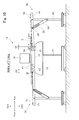
- Fig. 10 shows a case that the feeding rails of the rear side support base 60 and the front side support base 70 are set at respectively different inclination angles.
- the feeding auxiliary member 40 is disposed on only two rows from the front end.
- the front end part of the feeding rail 61 of the rear side support base 60 shown in Fig. 10 is located on a lower side with respect to its rear end part and the position of the carrying roller 62 of the front end part is set at the substantially same height as the feed roller 21 (height difference "H1" is substantially zero).
- the front end part of the feeding rail 71 of the front side support base 70 is located on a slightly lower side with respect to its rear end part and a height difference between the carrying roller 72 of the rear end part and the support roller 41 is set to be "H2".
- the inclination angle of the feeding rail 61 is set to be larger than the inclination angle of the feeding rail 71.
- the plate-like medium “B” can be surely fed in the front and rear direction.
- the height differences "H1" and “H2”, a distance “D1” in the front and rear direction between the feeding rail 61 and the feed roller 21, a distance “D2” in the front and rear direction between the feeding rail 71 and the platen 13, and the inclination angles of the feeding rails 61 and 71 shown in Fig. 10 are adjusted, for example, depending on the own weight and material (surface material) of the plate-like medium "B” so that the plate-like medium "B” is fed to the front side smoothly.
- the rear side support base 60 (front side support base 70) is structured as an example so that the inclination angle of the feeding rail 61 is adjusted by using the inclination adjusting plate 64 which is formed with the elongated hole 65.
- the present invention is not limited to this structure.
- the feeding rail 61 is fixed to a frame member 69 shown in Fig. 6 by using, for example, a screw.
- a spacer (for example, washer) having a thickness corresponding to the inclination direction and the inclination angle is sandwiched between the frame member 69 and the feeding rail 61. According to this structure, since the inclination angle is determined by the thickness of the spacer, the inclination angle can be easily reproduced.
- the rear side support base 60 and the front side support base 70 are used in an inclined state.
- the present invention is not limited to this structure.
- the rear side support base 60 and the front side support base 70 may be used by adjusting in a substantially horizontal state.
- the feed roller 21 is preferably used which is formed with material whose contact resistance is large. Further, an exchanging work of the feed roller 21 for preventing occurrence of slippage requires much labor.
- a structure for preventing occurrence of slippage in which the rear side support base 60 and the front side support base 70 are set to be inclined is simple and easy. Further, according to this structure, occurrence of slippage can be surely prevented regardless of material of the printing medium and the printing medium can be fed to the front side with a high degree of accuracy.
- the structure is shown as an example in which a plurality of the feeding auxiliary members 40 is provided in the platen 13 so as to be juxtaposed in the front and rear direction.
- the position of the feeding auxiliary member 40 provided in the platen 13 is not limited.
- the number and the disposed positions of the feeding auxiliary members 40 can be designed arbitrarily.
- the feeding auxiliary member 40 is structured as an example so that the support roller 41 is rotationally attached to the shaft member 42.
- the present invention is not limited to this structure. It may be structured that, for example, instead of the support roller 41, a plurality of members with a small sliding resistance is disposed so as to be slightly protruded from the upper face of the platen 13.
- printing is performed by using "UV" ink.
- the present invention may be also applied to a printer apparatus in which, for example, water-based ink, oil-based ink, solvent ink or the like is used.
Landscapes
- Handling Of Sheets (AREA)
- Ink Jet (AREA)
- Feeding Of Articles By Means Other Than Belts Or Rollers (AREA)
Abstract
Description
- The present invention relates to a printer apparatus in which ink is ejected from a printer head to perform printing on a printing medium and, more specifically, relates to a printer apparatus which is capable of printing on a plate-like printing medium.
- Conventionally, a printer apparatus (inkjet printer) has been known in which control for feeding a printing medium formed of a sheet-like material (hereinafter, referred to as a sheet-like medium) in a front and rear direction with respect to a platen and control for ejecting ink while moving a printer head facing the platen in a right and left direction are performed in a combined manner to perform printing on the printing medium. In recent years, in addition to a sheet-like medium, a printing medium formed of a plate-like material (hereinafter, referred to as a plate-like medium) has been required to be printed by the printer apparatus. In order to cope with the requirement, for example, a structure has been known in which a support member for horizontally supporting a plate-like medium is provided on a front side and a rear side of the platen. According to this structure, a plate-like medium is fed in the front and rear direction while being horizontally supported and printing can be performed on the plate-like medium.
- For example, in
Fig. 3 in Patent Literature 1, a structure is disclosed in which a first support arm 101 and a second support arm 103 are provided on a front side and a rear side of aplaten 10 to support a plate-like medium 20 horizontally and the plate-like medium 20 is moved in the front and rear direction by means of rotating afeed roller 15 is rotated. In the structure shown inFig. 3 in Patent Literature 1, the plate-like medium 20 is moved in the front and rear direction while an under face of the plate-like medium 20 is slid on an upper face of theplaten 10 by therotated feed roller 15.
[Patent Literature 1] Japanese Patent Laid-Open No.2002-301842 - Recently, a large-scale plate-like medium (for example, whose width in the right and left direction is about 1m and whose length in the front and rear direction is about 1.6m) is required to be printed. In a case that printing is performed on such a large-scale plate-like medium by using the structure shown in
Fig. 3 in Patent Literature 1, since a contacting area of the plate-like medium with theplaten 10 is wide, sliding resistance between the upper face of theplaten 10 and the under face of the plate-like medium is increased and thus an excessive load may be applied to thefeed roller 15. When an excessive load is applied to thefeed roller 15 as described above, for example, a slip may be easily occurred at an abutting portion of thefeed roller 15 with the plate-like medium and thus it is difficult to feed the plate-like medium in the front and rear direction with a high degree of accuracy while its positional accuracy is secured and, as a result, printing quality may be lowered. - In view of the problems described above, an objective of the present invention is to provide a printer apparatus in which a plate-like medium is fed in the front and rear direction with a high degree of accuracy and, as a result, printing quality is improved.
- In order to attain the above-mentioned objective, the present invention provides a printer apparatus in which ink is ejected to perform printing on a printing medium (for example, a sheet-like medium "S" or a plate-like medium "B" in the embodiment) while a printer head facing the printing medium is relatively moved in a feeding direction and a scanning direction perpendicular to each other with respect to the printing medium that is supported by a medium support means (for example, the
platen 13 in the embodiment) for supporting the printing medium, the printer apparatus including: - a medium feeding mechanism (for example, the front and
rear drive motor 25 in the embodiment) in which, in a state that the printing medium is pinched by pinching rollers (for example, thefeed roller 21 and thepinch roller 24 in the embodiment) that are paired and disposed on an upstream side in the feeding direction with respect to the medium support means, one of the pinching rollers is driven and rotated to feed the printing medium in the feeding direction so that the printing medium is located on the medium support means; - a head moving mechanism (for example, the right and
left drive motor 39 in the embodiment) which moves the printer head in the scanning direction; and - a print control part (for example, the
controller 19 in the embodiment) which performs control for feeding the printing medium by the medium feeding mechanism and control for moving the printer head by the head moving mechanism. - In the present invention, it is preferable that the feeding auxiliary member is provided with a support shaft (for example, the
shaft member 42 in the embodiment) and a rotation member (for example, thesupport roller 41 in the embodiment) which is rotationally attached to the support shaft, and the feeding auxiliary member is attached to the medium support means so that the support shaft is directed in the scanning direction, and an upper part of the rotation member is protruded on an upper side with respect to the support face. - Further, it is preferable that, in a case that a plate-like printing medium (for example, the plate-like medium "B" in the embodiment) is used as the printing medium, the plate-like printing medium being extended longer in the feeding direction than a length in the feeding direction of the medium support means and, when printing is to be performed while the plate-like printing medium is supported and fed in the feeding direction,
an upstream side support base (for example, the rearside support base 60 in the embodiment) is provided on the upstream side in the feeding direction with respect to the pinching rollers, the upstream side support base being detachably attached to the printer apparatus for supporting an unprinted portion of the plate-like printing medium,
a downstream side support base (for example, the frontside support base 70 in the embodiment) is provided on the downstream side in the feeding direction with respect to the medium support means, the downstream side support base being detachably attached to the printer apparatus for supporting a portion having been printed of the plate-like printing medium, and
the plate-like printing medium is supported by the upstream side support base and the downstream side support base and supported by the pinching rollers and the feeding auxiliary member and the plate-like printing medium is fed in a state separated from the support face. - It is preferable that each of the upstream side support base and the downstream side support base is structured of a medium support rail (for example, the
feeding rail 61 and thefeeding rail 71 in the embodiment), which supports the plate-like printing medium, and a rail support leg (for example, thesupport leg 63 in the embodiment) which is extended to a lower side with respect to the medium support rail for supporting the medium support rail,
an upstream side in the feeding direction of the medium support rail is located on an upper side or in a substantially horizontal state with respect to a downstream side in the feeding direction by means of adjusting an inclination angle of the medium support rail with respect to the rail support leg, and
a vertically positional relationship between an end part on the downstream side in the feeding direction of the upstream side support base and the pinching rollers is adjustable, and a vertically positional relationship between an end part on the upstream side in the feeding direction of the downstream side support base and the medium support means is adjustable. - The printer apparatus in accordance with the present invention is structured so that the medium support means is provided with the feeding auxiliary member, which is protruded with respect to the support face, on a downstream side in the feeding direction with respect to a portion facing the printer head. According to this structure, for example, when printing is to be performed on a plate-like printing medium having a certain degree of rigidity, the printing medium is fed in a supported state by the pinching rollers and the feeding auxiliary member and thus the printing medium and the medium support means can be prevented from directly contacting with each other. Therefore, for example, when printing is to be performed on a large-scale and heavy plate-like printing medium, sliding resistance occurring between the plate-like printing medium and the medium support means is reduced and thus the plate-like printing medium can be fed by a relatively small force. Accordingly, a slip does not occur in the abutting portion of the pinching roller for feeding the plate-like printing medium in the feeding direction with the plate-like printing medium and thus the plate-like printing medium is fed in the feeding direction with a high degree of accuracy while securing its positional accuracy and a high-quality printing is attained.
- In the present invention, it is preferable that the feeding auxiliary member is provided with a support shaft and a rotation member which is rotationally attached to the support shaft and the upper part of the rotation member is protruded to an upper side with respect to the support face of the medium support means. According to this structure, for example, when the plate-like printing medium is to be fed in the feeding direction, since the rotation member supports the plate-like printing medium while being rotated, the plate-like printing medium is fed in the feeding direction smoothly. Therefore, a slip does not occur in the abutting portion of the pinching roller with the plate-like printing medium and thus the plate-like printing medium is fed in the feeding direction with a high degree of accuracy.
- Further, it is preferable that, when printing is to be performed on a plate-like printing medium which is longer than a length in the feeding direction of the medium support means, an upstream side support base and a downstream side support base are provided for supporting the plate-like printing medium. According to this structure, the plate-like printing medium can be fed on the medium support means so as to be substantially horizontal state and the plate-like printing medium is supported by the pinching roller and the feeding auxiliary member and can be fed in a separated state from the support face on the medium support means. Therefore, sliding resistance occurring between the plate-like printing medium and the medium support means is reduced and thus the plate-like printing medium can be fed with a small force.
- It is preferable that each of the upstream side support base and the downstream side support base is structured of a medium support rail which supports the plate-like printing medium, and a rail support leg for supporting the medium support rail, and an inclination angle of the medium support rail with respect to the rail support leg is adjustable. When an inclination angle of the medium support rail of each of the upstream side support base and the downstream side support base is set so that, for example, its upstream side in the feeding direction is a little higher, the plate-like printing medium is fed from a higher position to a lower position as a whole at the time of feeding in the feeding direction. Therefore, the plate-like printing medium can be fed in the feeding direction smoothly without operating against the gravity.
-
- [
Fig. 1 ]
Fig. 1 is a perspective view showing a printer apparatus (state where printing is performed on a sheet-like medium) to which the present invention is applied. - [
Fig. 2 ]
Fig. 2 is a perspective view showing a printing unit and its vicinity of the printer apparatus. - [
Fig. 3 ]
Fig. 3 is a perspective view showing a platen of the printer apparatus. - [
Fig. 4 ]
Fig. 4 is a cross-sectional view showing a IV-IV portion inFig. 3 . - [
Fig. 5 ]
Fig. 5 is a perspective view showing the printer apparatus (state where printing is performed on a plate-like medium) which is viewed from an obliquely front side. - [
Fig. 6 ]
Fig. 6 is a perspective view showing the printer apparatus (state where printing is performed on a plate-like medium) which is viewed from an obliquely rear side. - [
Fig. 7 ]
Fig. 7 is a side view showing a state when printing on a plate-like medium is started. - [
Fig. 8 ]
Fig. 8 is a side view showing a state when printing on a plate-like medium has been finished. - [
Fig. 9 ]
Fig. 9 is a side view showing a rear side support base when it is not used (at the time of storage). - [
Fig. 10 ]
Fig. 10 is a side view showing a state where a plate-like medium is supported under a state where an inclination angle is changed and printing is performed. -
- "B"
- plate-like medium (printing medium, plate-like printing medium)
- "S"
- sheet-like medium (printing medium)
- 10
- printer apparatus
- 13
- platen (medium support means)
- 19
- controller (print control part)
- 21
- feed roller (pinching roller)
- 24
- pinch roller (pinching roller)
- 25
- front and rear drive motor (medium feeding mechanism)
- 32
- printer head
- 39
- right and left drive motor (head moving mechanism)
- 40
- feeding auxiliary member
- 41
- support roller (rotation member)
- 42
- shaft member (support shaft)
- 60
- rear side support base (upstream side support base)
- 61
- feeding rail (medium support rail)
- 63
- support leg (rail support leg)
- 70
- front side support base (downstream side support base)
- A preferred embodiment of the present invention will be described below with reference to the accompanying drawings. In the following description, directions in the drawings indicated by the arrows are respectively defined as right and left, front and rear and upper and lower for convenience of description.
- A structure of a
printer apparatus 10 to which the present invention is applied will be described below with reference toFigs. 1 through 6 . Theprinter apparatus 10 is originally structured as shown inFig. 1 and printing can be performed on a sheet-like medium "S" by using this structure. On the other hand, when printing is to be performed on a plate-like medium, as shown inFigs. 5 and6 , a rearside support base 60 and a frontside support base 70 which will be described below are attached to theprinter apparatus 10. As described above, theprinter apparatus 10 is capable of printing for both of a sheet-like medium "S" and a plate-like medium. In the following description, as an example, a structure will be described in which printing is performed by using an ultraviolet curing type ink (hereinafter, referred to as "UV" ink) which is cured by irradiation of ultraviolet rays. - The
printer apparatus 10 is, as shown inFig. 1 , structured of asupport leg 11 having right and leftsupport legs center body part 12 supported by thesupport leg 11, aleft body part 14 provided on a left side of thecenter body part 12, aright body part 15 provided on a right side of thecenter body part 12, and anupper body part 16 which connects the right and leftbody parts center body part 12 in a separated and parallel manner. Thecenter body part 12 is provided with a flat plate-shapedplaten 13 which is exposed on its upper face and extended in the right and left direction. Anoperation part 18 which is structured of operation switches, display devices and the like is provided on a front face side at a left end part of thecenter body part 12. - The left end part of the
center body part 12 is incorporated with acontroller 19. Thecontroller 19 outputs operation signals to respective structure parts of theprinter apparatus 10 which will be described below to drive and control the respective structure parts. Specifically, thecontroller 19 drives and controls a vertically moving mechanism (not shown), a front andrear drive motor 25, printer heads 32, a right ultravioletray irradiation device 33R, a left ultravioletray irradiation device 33L, and a right and leftdrive motor 39, and the like which will be described below. Aguide rail 17 extended in the right and left direction is provided on a front face side at a lower part of theupper body part 16. Aprinting unit 30 is attached to theguide rail 17 so as to be movable in the right and left direction. - The
printing unit 30 is, as shown inFig. 2 , mainly structured of acarriage 31, the printer heads 32, the right ultravioletray irradiation device 33R and the left ultravioletray irradiation device 33L. Theprinting unit 30 is, for example, provided with a vertically moving mechanism (not shown) for moving theprinting unit 30 in an upper and lower direction with respect to theguide rail 17 depending on a thickness of a printing medium (sheet-like medium "S" or plate-like medium "B") to be printed. Therefore, a distance between the printer heads 32 and a printing medium can be set in a predetermined distance which is suitable for printing by the vertically moving mechanism regardless of the thickness of a printing medium that is to be used. - As a mechanism for moving the
printing unit 30 along theguide rail 17 reciprocatedly in the right and left direction, for example, a mechanism may be utilized in which thecarriage 31 and a right and left carrying belt (not shown) which is arranged on an inside of theupper body part 16 so as to be extended in the right and left direction are connected with each other and the right and left carrying belt is driven by the right and left drive motor 39 (seeFig. 1 ) which is provided in theright body part 15. - A rear face side of the
carriage 31 is fitted to theguide rail 17 so that thecarriage 31 is reciprocatedly movable along theguide rail 17 in the right and left direction. Further, thecarriage 31 is a mounting base for the printer heads 32, the right ultravioletray irradiation device 33R and the left ultravioletray irradiation device 33L. The printer heads 32 are, for example, structured of a "Magenta" head, a "Yellow" head, a "Cyan" head and a "Black" head. An under face of each of the printer heads 32 is formed with a plurality of ejection nozzles (not shown) for ejecting "UV" ink toward a lower side. - The right ultraviolet
ray irradiation device 33R is adjacently mounted on the right side of the printer heads 32. The right ultravioletray irradiation device 33R is mounted with a light source such as an LED in its inside for irradiating ultraviolet rays. Ultraviolet rays are irradiated from the light source toward the lower side. The left ultravioletray irradiation device 33L is provided with the same structure as the right ultravioletray irradiation device 33R and is adjacently mounted on the left side of the printer heads 32. The "UV" ink which is ejected from theprinter head 32 and adhered to a printing medium is surely cured by ultraviolet rays irradiated from the right ultravioletray irradiation device 33R and the left ultravioletray irradiation device 33L. - As shown in
Fig. 2 , a plurality ofclamp devices 23 is attached to a lower part of theupper body part 16 side by side in the right and left direction. Apinch roller 24 is rotationally attached to a tip end part on the front side of theclamp device 23. A lower side of thepinch roller 24 is disposed with afeed roller 21 formed in a cylindrical tube shape and extended in the right and left direction so as to protrude with respect to the upper face of the platen 13 (seeFigs. 7 and8 ). Thefeed roller 21 is rotationally driven, for example, by the front andrear drive motor 25 provided in the inside of thecenter body part 12. - The
clamp device 23 is capable of being set at a clamp position where thepinch roller 24 is pressed against thefeed roller 21 and at an unclamp position where thepinch roller 24 is separated from thefeed roller 21. According to this structure, in a state that theclamp device 23 is set at a clamp position so that a printing medium is pinched between thepinch roller 24 and thefeed roller 21, when thefeed roller 21 is rotated, the printing medium is fed to the front side or rear side by a predetermined distance. An abutting portion of a surface of thefeed roller 21 with thepinch roller 24 is, for example, stuck and fixed with ametal mesh member 22. According to this structure, contact resistance of thefeed roller 21 with the printing medium is increased and thus the printing medium can be fed to the front side and the rear side with a high degree of accuracy without occurring a slip. - Further, a plurality of
suction holes 13a is formed in theplaten 13 and an under face of theplaten 13 is provided with a decompression chamber (not shown) which is in communication with thesuction holes 13a. For example, when printing is to be performed on a sheet-like medium "S", the sheet-like medium "S" is sucked and fixed to the upper face of theplaten 13 by means of setting the decompression chamber at a negative pressure. - In the structure described above, when printing is to be performed on a sheet-like medium "S", in a state that the sheet-like medium "S" is sucked and fixed to the
platen 13, "UV" ink is ejected and ultraviolet rays are irradiated while theprinting unit 30 is moved in the right and left direction to perform printing. Then, suction of a sheet-like medium "S" to theplaten 13 is released and, after the sheet-like medium "S" is fed by a predetermined distance to the front side, the sheet-like medium "S" is fixed to theplaten 13 again and ejection of the "UV" ink and irradiation of the ultraviolet rays are performed. Desired printing is performed on the sheet-like medium "S" by performing this operation repeatedly. - In addition to the structure described above, in the
printer apparatus 10 to which the present invention is applied, especially for performing printing on a plate-like medium "B", a plurality of feedingauxiliary members 40 is provided in theplaten 13 for feeding the plate-like medium "B" in the front and rear direction with a high degree of accuracy. Structure of the feedingauxiliary member 40 will be described below with further reference toFigs. 3 and4 . - A portion surrounded by two-dot chain line in
Fig. 3 is an exploded perspective view showing the feedingauxiliary member 40. As shown in the exploded perspective view, the feedingauxiliary member 40 is structured of asupport roller 41, ashaft member 42, twowashers 43 and twopressing metal fittings 44. Thesupport roller 41 is formed in a ring shape, for example, by using metal material. Further, a bearing, for example, whose outer peripheral diameter is about 7mm and inner peripheral diameter is about 3mm may be used as thesupport roller 41. Theshaft member 42 is a shaft which is, for example, formed of metal material and theshaft member 42 is inserted into a center opening part of thesupport roller 41 in the right and left direction. - The
washer 43 is formed in a ring shape, for example, by using metal material. Further, theshaft member 42 is inserted into a center opening part of thewasher 43 and twowashers 43 are located separately on the right and left sides of thesupport roller 41. In a state that theshaft member 42 is inserted into thesupport roller 41 and thewashers 43, thesupport roller 41 and thewashers 43 are rotatable with respect to theshaft member 42. Thepressing metal fitting 44 is formed in a plate shape, for example, by using SUS (stainless steel) whose thickness is about 0.15-0.20mm. - After the respective members described above have been assembled as the feeding
auxiliary member 40 which is shown at the middle position inFig. 3 , the feedingauxiliary member 40 is accommodated in an accommodating recessedpart 13b formed in theplaten 13 in a state that theshaft member 42 is directed in the right and left direction. Then, when two fixingscrews 45 are fastened, the feedingauxiliary member 40 is fixed to theplaten 13.Fig. 4 is a cross-sectional view showing a state where the feedingauxiliary member 40 is fixed to theplaten 13. As shown inFig. 4 , theshaft member 42 is pressed and fixed to theplaten 13 by thepressing metal fittings 44 and thesupport roller 41 is rotatable with respect to the fixedshaft member 42. In this fixed state, an upper end part of thesupport roller 41 is protruded about 0.1mm from the upper face of theplaten 13. - When printing is to be performed on a plate-like medium "B" by using the
printer apparatus 10 which is structured as described above, a rearside support base 60 is provided on a rear side of theprinter apparatus 10 and a frontside support base 70 is provided on its front side in order to support the plate-like medium "B" in a substantially horizontal state (seeFigs. 5 and6 ). A structure of the rearside support base 60 will be described below with further reference toFig. 6 . The structure of the frontside support base 70 is the same as that of the rearside support base 60 and thus its description is omitted. - As shown in
Fig. 6 , the rearside support base 60 is structured so that a feedingrail 61 whose length in the front and rear direction is about 1.2m and on which a plurality of carryingrollers 62 is adjacently disposed in the front and rear direction is swingably supported bysupport legs 63. Aninclination adjusting plate 64 is attached so as to connect the feedingrail 61 with thesupport leg 63 and theinclination adjusting plate 64 is swingably attached to thesupport leg 63. Theinclination adjusting plate 64 is formed with anelongated hole 65. In this structure, when a fixingscrew 66 is inserted into theelongated hole 65 and fastened to the feedingrail 61, theinclination adjusting plate 64 and the feedingrail 61 are fixed to each other and an inclination angle of the feedingrail 61 can be arbitrarily set with respect to thesupport leg 63. - For example, as shown in
Figs. 5 and6 , the feedingrail 61 may be fixed in a substantially horizontal state or, as shown inFig. 9 , the feedingrail 61 may be inclined downward to be folded. When the rearside support base 60 is not used, the rearside support base 60 can be stored in a compact folded state as shown inFig. 9 and thus saving of a storage space can be attained. - Next, in a state that the rear
side support base 60 and the frontside support base 70 are arranged to theprinter apparatus 10, an operation will be described below with further reference toFigs. 7 and8 when printing is performed on a plate-like medium "B", for example, whose width in the right and left direction is about 1m and whose length in the front and rear direction is about 1.6m while the plate-like medium "B" is fed to the front side.Fig. 7 is a side view showing a state when printing is started on a plate-like medium "B" andFig. 8 is a side view showing a state when printing on the plate-like medium "B" has been finished. - First, an attaching method will be described below in which how the rear
side support base 60 and the frontside support base 70 are arranged to theprinter apparatus 10 is explained. In the rearside support base 60, an inclination angle of the feedingrail 61 with respect to thesupport leg 63 is set so that the rear end part of the feedingrail 61 is higher about 10-20mm than its front end part (the feedingrail 61 is inclined forward) (seeFig. 7 ). Similarly, in the frontside support base 70, an inclination angle of the feeding rail is set so that the rear end part of the feeding rail is higher about 10-20mm than its front end part (seeFig. 7 ). - According to the above-mentioned setting, when a plate-like medium "B" is to be fed to the front side, printing can be performed while feeding from a higher position to a lower position as a whole. Therefore, the plate-like medium "B" can be fed forward smoothly and an excessive load is prevented from being applied to the front and rear drive motor 25 (feed roller 21). Therefore, a slip does not occur between the
feed roller 21 and the plate-like medium "B" and the plate-like medium "B" can be fed to the front side with a high degree of accuracy according to driving of the front andrear drive motor 25. - The rear
side support base 60 and the frontside support base 70 whose inclination angles are set as described above are arranged on the rear side and the front side of theprinter apparatus 10. Then, a plate-like medium "B" is placed on the rearside support base 60 and fed to the front side and, as a result, the plate-like medium "B" is pinched between thepinch rollers 24 and thefeed roller 21 and theclamp device 23 is set at the clamp position. In this state, thefeed roller 21 is rotated and a front end portion of the plate-like medium "B" is set to be located on a lower side of the printer heads 32 (seeFig. 7 ). - A "burr" which is formed, for example, when a plate-like medium "B" is performed with a cutting work in a predetermined dimension may be left at a front end part of the plate-like medium "B", or a front end part of the plate-like medium "B" may be curved toward the lower side. Also in this case, since the front end part of the plate-like medium "B" is supported by the
support rollers 41 from the lower side, the plate-like medium "B" can be smoothly fed to the front side in a floated state without contacting with the upper face of theplaten 13. Therefore, the front end part of the plate-like medium "B" and the upper face of theplaten 13 are prevented from being abutted with each other and thus an excessive contacting resistance does not occur. - After the plate-like medium "B" has been fed to a position shown in
Fig. 7 , a desired printing is performed from a front end part of the plate-like medium "B" to its rear side while performing control which rotates thefeed roller 21 for feeding the plate-like medium "B" to the front side and control which moves thecarriage 31 in the right and left direction in a combined manner. In this case, as shown inFig. 8 , the plate-like medium "B" is fed to the front side in a state supported by a plurality of thesupport rollers 41 and thefeed roller 21 from the lower side and thus the plate-like medium "B" is not contacted with the upper face of theplaten 13. - Further, the
support roller 41 is rotatable with respect to thesupport shaft 42 fixed to be extended in the right and left direction (rotatable along a moving direction of the plate-like medium "B") and thus the plate-like medium "B" can be fed to the front side smoothly. Therefore, a slip does not occur at an abutting portion of thefeed roller 21 with the plate-like medium "B" and thus the plate-like medium "B" is fed to the front side by a rotated amount of thefeed roller 21 with a high degree of accuracy and a high-quality printing secured with a high degree of positional accuracy can be attained. - In a state that the printing on the plate-like medium "B" has been completed as shown in
Fig. 8 , thefeed roller 21 is rotated to feed the plate-like medium "B" on which printing has been completed to the front side and the plate-like medium "B" is taken out from the frontside support base 70. Then, another plate-like medium "B" on which printing is not performed is placed on the rearside support base 60. A front end part of the plate-like medium "B" placed on the rearside support base 60 is pinched between thepinch roller 24 and thefeed roller 21 and theclamp device 23 is set at the clamp position. In this state, thefeed roller 21 is rotated so that the front end portion of the plate-like medium "B" is located on the lower side of the printer heads 32 as shown inFig. 7 and printing is started. When this operation is repeatedly performed, a high-quality printing can be performed on a plurality of plate-like media "B" with a high degree of efficiency - In the embodiment described above, a structure is shown as an example in which five accommodating recessed
parts 13b are formed in theplaten 13 so as to be juxtaposed in the front and rear direction and each of the accommodating recessedparts 13b is accommodated with the feedingauxiliary member 40. However, the present invention is not limited to this structure. For example, like the accommodating recessedparts 13c hatched inFig. 2 , it may be structured that only two rows of the accommodating recessedparts 13c are formed from the front end in theplaten 13 and the feedingauxiliary member 40 is accommodated into the accommodating recessedpart 13c. According to this structure, while attaining the above-mentioned effects, the number of the feedingauxiliary members 40 and the manufacturing number for the accommodating recessedpart 13c are reduced and thus a manufacturing cost can be reduced. Further, in this structure, the feedingauxiliary member 40 is not disposed at a portion of theplaten 13 facing the printer heads 32 and thus theplaten 13 can be structured completely flatly Therefore, for example, when printing is to be performed on a soft sheet-like medium "S", ink from theprinter head 32 is stuck to a portion of the soft sheet-like medium "S" which is sucked by theplaten 13 to be completely flat shape and thus a high-quality printing can be attained. - Further, in the embodiment described above, as shown in
Figs. 7 and8 , each of the rearside support base 60 and the frontside support base 70 is set obliquely so that the rear end part of the feeding rail is set higher about 10-20mm than its front end part. However, the present invention is not limited to this embodiment. For example, the feeding rails of the rearside support base 60 and the frontside support base 70 may be set at respectively different inclination angles. -
Fig. 10 shows a case that the feeding rails of the rearside support base 60 and the frontside support base 70 are set at respectively different inclination angles. In theplaten 13 shown inFig. 10 , the feedingauxiliary member 40 is disposed on only two rows from the front end. The front end part of the feedingrail 61 of the rearside support base 60 shown inFig. 10 is located on a lower side with respect to its rear end part and the position of the carryingroller 62 of the front end part is set at the substantially same height as the feed roller 21 (height difference "H1" is substantially zero). The front end part of the feedingrail 71 of the frontside support base 70 is located on a slightly lower side with respect to its rear end part and a height difference between the carryingroller 72 of the rear end part and thesupport roller 41 is set to be "H2". The inclination angle of the feedingrail 61 is set to be larger than the inclination angle of the feedingrail 71. - As shown in
Fig. 10 , since the feedingrail 61 is inclined, a plate-like medium "B" is smoothly fed to thefeed roller 21 by its own weight. Further, since the height difference between the carryingroller 72 and thesupport roller 41 is set to be "H2", the plate-like medium "B" on which printing has been performed is resiliently bent without contacting the carryingroller 72 on the rear side of the feedingrail 71 with the plate-like medium "B" and the plate-like medium "B" is contacted with the carryingroller 72 in the vicinity of the center of the feedingrail 71. Therefore, since the number of the carryingrollers 72 contacting with the plate-like medium "B" is reduced, resistance acting in the front and rear direction at the time of feeding the plate-like medium "B" is reduced and, even when a further small force is applied, the plate-like medium "B" can be surely fed in the front and rear direction. In addition, the height differences "H1" and "H2", a distance "D1" in the front and rear direction between the feedingrail 61 and thefeed roller 21, a distance "D2" in the front and rear direction between the feedingrail 71 and theplaten 13, and the inclination angles of the feeding rails 61 and 71 shown inFig. 10 are adjusted, for example, depending on the own weight and material (surface material) of the plate-like medium "B" so that the plate-like medium "B" is fed to the front side smoothly. - In the embodiment described above, the rear side support base 60 (front side support base 70) is structured as an example so that the inclination angle of the feeding
rail 61 is adjusted by using theinclination adjusting plate 64 which is formed with theelongated hole 65. However, the present invention is not limited to this structure. Instead of using the above-mentionedinclination adjusting plate 64, the feedingrail 61 is fixed to aframe member 69 shown inFig. 6 by using, for example, a screw. Further, a spacer (for example, washer) having a thickness corresponding to the inclination direction and the inclination angle is sandwiched between theframe member 69 and the feedingrail 61. According to this structure, since the inclination angle is determined by the thickness of the spacer, the inclination angle can be easily reproduced. - In the embodiment described above, the rear
side support base 60 and the frontside support base 70 are used in an inclined state. However, the present invention is not limited to this structure. For example, the rearside support base 60 and the frontside support base 70 may be used by adjusting in a substantially horizontal state. In this case, in order that a slip does not occur between thefeed roller 21 and a plate-like medium "B", thefeed roller 21 is preferably used which is formed with material whose contact resistance is large. Further, an exchanging work of thefeed roller 21 for preventing occurrence of slippage requires much labor. On the other hand, a structure for preventing occurrence of slippage in which the rearside support base 60 and the frontside support base 70 are set to be inclined is simple and easy. Further, according to this structure, occurrence of slippage can be surely prevented regardless of material of the printing medium and the printing medium can be fed to the front side with a high degree of accuracy. - In the embodiment described above, the structure is shown as an example in which a plurality of the feeding
auxiliary members 40 is provided in theplaten 13 so as to be juxtaposed in the front and rear direction. However, the position of the feedingauxiliary member 40 provided in theplaten 13 is not limited. When the plate-like medium "B" is capable of being fed in the front and rear direction without being contacted with theplaten 13, the number and the disposed positions of the feedingauxiliary members 40 can be designed arbitrarily. - Further, in the embodiment described above, the feeding
auxiliary member 40 is structured as an example so that thesupport roller 41 is rotationally attached to theshaft member 42. However, the present invention is not limited to this structure. It may be structured that, for example, instead of thesupport roller 41, a plurality of members with a small sliding resistance is disposed so as to be slightly protruded from the upper face of theplaten 13. - In the embodiment described above, printing is performed by using "UV" ink. However, the present invention may be also applied to a printer apparatus in which, for example, water-based ink, oil-based ink, solvent ink or the like is used.
Claims (4)
- A printer apparatus in which ink is ejected to perform printing on a printing medium while a printer head facing the printing medium is relatively moved in a feeding direction and a scanning direction perpendicular to each other with respect to the printing medium that is supported by a medium support means for supporting the printing medium, the printer apparatus comprising:a medium feeding mechanism in which, in a state that the printing medium is pinched by a pair of pinching rollers that are disposed on an upstream side in the feeding direction with respect to the medium support means, one of the pinching rollers is driven and rotated to feed the printing medium in the feeding direction so that the printing medium is located on the medium support means;a head moving mechanism which moves the printer head in the scanning direction; anda print control part which performs control for feeding the printing medium by the medium feeding mechanism and control for moving the printer head by the head moving mechanism;wherein the medium support means is provided with a feeding auxiliary member which is protruded with respect to a support face for supporting the printing medium on a downstream side in the feeding direction with respect to a portion facing the printer head.
- The printer apparatus according to claim 1, wherein
the feeding auxiliary member is provided with a support shaft and a rotation member which is rotationally attached to the support shaft,
the feeding auxiliary member is attached to the medium support means so that the support shaft is directed in the scanning direction, and
an upper part of the rotation member is protruded on an upper side with respect to the support face. - The printer apparatus according to claim 1 or 2, wherein
in a case that a plate-like printing medium is used as the printing medium, the plate-like printing medium being extended longer in the feeding direction than a length in the feeding direction of the medium support means and, when printing is to be performed while the plate-like printing medium is supported and fed in the feeding direction,
an upstream side support base is provided on the upstream side in the feeding direction with respect to the pinching rollers, the upstream side support base being detachably attached to the printer apparatus for supporting an unprinted portion of the plate-like printing medium,
a downstream side support base is provided on the downstream side in the feeding direction with respect to the medium support means, the downstream side support base being detachably attached to the printer apparatus for supporting a portion having been printed of the plate-like printing medium, and
the plate-like printing medium is supported by the upstream side support base and the downstream side support base and supported by the pinching rollers and the feeding auxiliary member and the plate-like printing medium is fed in a state separated from the support face. - The printer apparatus according to claim 3, wherein
each of the upstream side support base and the downstream side support base is structured of a medium support rail, which supports the plate-like printing medium, and a rail support leg which is extended to a lower side with respect to the medium support rail for supporting the medium support rail,
an upstream side in the feeding direction of the medium support rail is located on an upper side or in a substantially horizontal state with respect to a downstream side in the feeding direction by means of adjusting an inclination angle of the medium support rail with respect to the rail support leg, and
a vertically positional relationship between an end part on the downstream side in the feeding direction of the upstream side support base and the pinching rollers is adjustable, and a vertically positional relationship between an end part on the upstream side in the feeding direction of the downstream side support base and the medium support means is adjustable.
Applications Claiming Priority (1)
| Application Number | Priority Date | Filing Date | Title |
|---|---|---|---|
| PCT/JP2009/054939 WO2010103664A1 (en) | 2009-03-13 | 2009-03-13 | Printer device |
Publications (3)
| Publication Number | Publication Date |
|---|---|
| EP2407311A1 true EP2407311A1 (en) | 2012-01-18 |
| EP2407311A4 EP2407311A4 (en) | 2012-06-20 |
| EP2407311B1 EP2407311B1 (en) | 2013-08-07 |
Family
ID=42727970
Family Applications (1)
| Application Number | Title | Priority Date | Filing Date |
|---|---|---|---|
| EP09841492.3A Not-in-force EP2407311B1 (en) | 2009-03-13 | 2009-03-13 | Printer device |
Country Status (6)
| Country | Link |
|---|---|
| US (1) | US8721067B2 (en) |
| EP (1) | EP2407311B1 (en) |
| JP (1) | JP5242770B2 (en) |
| KR (1) | KR101321038B1 (en) |
| CN (1) | CN102341246B (en) |
| WO (1) | WO2010103664A1 (en) |
Cited By (1)
| Publication number | Priority date | Publication date | Assignee | Title |
|---|---|---|---|---|
| WO2017068050A1 (en) * | 2015-10-23 | 2017-04-27 | Agfa Graphics Nv | Inkjet printing device with removable flat substrate support device |
Families Citing this family (16)
| Publication number | Priority date | Publication date | Assignee | Title |
|---|---|---|---|---|
| JP2012229064A (en) * | 2011-04-22 | 2012-11-22 | Roland Dg Corp | Image forming device |
| CN103231592A (en) * | 2013-05-15 | 2013-08-07 | 济南优诺思喷印设备有限公司 | Height-adjustable printer trolley |
| CN103253013A (en) * | 2013-05-15 | 2013-08-21 | 济南优诺思喷印设备有限公司 | Printer dolly with ultraviolet curing function |
| CN103213411A (en) * | 2013-05-15 | 2013-07-24 | 济南优诺思喷印设备有限公司 | Printer car for 3D (three-dimensional) figures |
| US9156285B2 (en) * | 2013-09-30 | 2015-10-13 | Eastman Kodak Company | Integrated vacuum assist web transport system |
| US9079428B2 (en) | 2013-09-30 | 2015-07-14 | Eastman Kodak Company | Vacuum transport roller for web transport system |
| US9050835B2 (en) | 2013-09-30 | 2015-06-09 | Eastman Kodak Company | Vacuum pulldown of print medium in printing system |
| US9085176B2 (en) | 2013-09-30 | 2015-07-21 | Eastman Kodak Company | Vacuum pulldown of print medium in printing system |
| JP5946108B2 (en) * | 2014-02-04 | 2016-07-05 | 江沢事務器株式会社 | Surface modification device for printing |
| KR101879036B1 (en) * | 2016-06-21 | 2018-07-16 | 채명석 | Leather fabric feed mechanism for Digital inkjet printer |
| US11298963B2 (en) | 2017-11-29 | 2022-04-12 | Landa Corporation Ltd. | Protection of components of digital printing systems |
| CN113646248B (en) | 2019-04-03 | 2024-06-11 | 兰达公司 | Digital printing system having a paper conveyor provided with a rotatable element to eliminate damage to the paper |
| WO2022071939A1 (en) * | 2020-09-30 | 2022-04-07 | Hewlett-Packard Development Company, L.P. | Media bypass for a printer |
| JP7800176B2 (en) * | 2021-03-30 | 2026-01-16 | 株式会社リコー | Image forming device |
| US12134265B2 (en) | 2021-03-30 | 2024-11-05 | Ricoh Company, Ltd. | Image forming apparatus |
| JP7585939B2 (en) | 2021-03-30 | 2024-11-19 | 株式会社リコー | Image forming device |
Family Cites Families (5)
| Publication number | Priority date | Publication date | Assignee | Title |
|---|---|---|---|---|
| DE69829752T2 (en) * | 1998-10-30 | 2006-02-09 | Hewlett-Packard Development Co., L.P., Houston | Paper-picture device and data-carrier output method |
| JP4460186B2 (en) | 2001-04-04 | 2010-05-12 | 株式会社ミマキエンジニアリング | Platen extension tool for inkjet printer |
| JP3960244B2 (en) * | 2003-03-26 | 2007-08-15 | ブラザー工業株式会社 | Image forming apparatus and paper tray |
| US7431278B2 (en) * | 2003-03-26 | 2008-10-07 | Brother Kogyo Kabushiki Kaisha | Image forming apparatus and platen used therein |
| JP2008201107A (en) * | 2007-02-22 | 2008-09-04 | Roland Dg Corp | Image forming apparatus and recording medium supporting apparatus |
-
2009
- 2009-03-13 JP JP2011503632A patent/JP5242770B2/en active Active
- 2009-03-13 WO PCT/JP2009/054939 patent/WO2010103664A1/en not_active Ceased
- 2009-03-13 CN CN200980157748XA patent/CN102341246B/en not_active Expired - Fee Related
- 2009-03-13 US US13/254,858 patent/US8721067B2/en active Active
- 2009-03-13 EP EP09841492.3A patent/EP2407311B1/en not_active Not-in-force
- 2009-03-13 KR KR1020117017421A patent/KR101321038B1/en not_active Expired - Fee Related
Non-Patent Citations (2)
| Title |
|---|
| No further relevant documents disclosed * |
| See also references of WO2010103664A1 * |
Cited By (2)
| Publication number | Priority date | Publication date | Assignee | Title |
|---|---|---|---|---|
| WO2017068050A1 (en) * | 2015-10-23 | 2017-04-27 | Agfa Graphics Nv | Inkjet printing device with removable flat substrate support device |
| US10369815B2 (en) | 2015-10-23 | 2019-08-06 | Agfa Nv | Inkjet printing device with removable flat substrate support device |
Also Published As
| Publication number | Publication date |
|---|---|
| CN102341246A (en) | 2012-02-01 |
| JPWO2010103664A1 (en) | 2012-09-10 |
| KR101321038B1 (en) | 2013-10-23 |
| WO2010103664A1 (en) | 2010-09-16 |
| US8721067B2 (en) | 2014-05-13 |
| CN102341246B (en) | 2013-10-23 |
| EP2407311A4 (en) | 2012-06-20 |
| KR20110110230A (en) | 2011-10-06 |
| JP5242770B2 (en) | 2013-07-24 |
| US20110316924A1 (en) | 2011-12-29 |
| EP2407311B1 (en) | 2013-08-07 |
Similar Documents
| Publication | Publication Date | Title |
|---|---|---|
| EP2407311B1 (en) | Printer device | |
| EP2385009B1 (en) | Inkjet printer | |
| EP1974932B1 (en) | Printer-plotter | |
| JP5143915B2 (en) | Printer device | |
| EP2384897A1 (en) | Ink jet printer | |
| JP5100491B2 (en) | Printer device | |
| EP2476638B1 (en) | Printer device and roller assembly | |
| KR20180078273A (en) | Printing apparatus using jig for cylindrical printing and jig for cylindrical printing | |
| JP4185377B2 (en) | Recording head mounting mechanism in an ink jet printer | |
| US8277038B2 (en) | Ink jet printer | |
| JP2013056522A (en) | Liquid droplet ejecting apparatus | |
| JP2011083973A (en) | Printer | |
| JP7694113B2 (en) | Movement mechanism and printing device | |
| JP6374617B2 (en) | Cylindrical printing jig and printing apparatus using cylindrical printing jig | |
| JP2012218339A (en) | Printer | |
| JP5458379B2 (en) | Printer device and roller assembly | |
| JP2025088870A (en) | Media Processing Device | |
| JPH10129056A (en) | Ink jet recorder | |
| JP3141924B2 (en) | Paper ejection mechanism of printer |
Legal Events
| Date | Code | Title | Description |
|---|---|---|---|
| PUAI | Public reference made under article 153(3) epc to a published international application that has entered the european phase |
Free format text: ORIGINAL CODE: 0009012 |
|
| 17P | Request for examination filed |
Effective date: 20110711 |
|
| AK | Designated contracting states |
Kind code of ref document: A1 Designated state(s): AT BE BG CH CY CZ DE DK EE ES FI FR GB GR HR HU IE IS IT LI LT LU LV MC MK MT NL NO PL PT RO SE SI SK TR |
|
| REG | Reference to a national code |
Ref country code: DE Ref legal event code: R079 Ref document number: 602009017882 Country of ref document: DE Free format text: PREVIOUS MAIN CLASS: B41J0011020000 Ipc: B41J0011000000 |
|
| A4 | Supplementary search report drawn up and despatched |
Effective date: 20120521 |
|
| DAX | Request for extension of the european patent (deleted) | ||
| RIC1 | Information provided on ipc code assigned before grant |
Ipc: B41J 11/00 20060101AFI20120514BHEP Ipc: B41J 11/06 20060101ALI20120514BHEP |
|
| 17Q | First examination report despatched |
Effective date: 20121120 |
|
| GRAP | Despatch of communication of intention to grant a patent |
Free format text: ORIGINAL CODE: EPIDOSNIGR1 |
|
| GRAS | Grant fee paid |
Free format text: ORIGINAL CODE: EPIDOSNIGR3 |
|
| GRAA | (expected) grant |
Free format text: ORIGINAL CODE: 0009210 |
|
| AK | Designated contracting states |
Kind code of ref document: B1 Designated state(s): AT BE BG CH CY CZ DE DK EE ES FI FR GB GR HR HU IE IS IT LI LT LU LV MC MK MT NL NO PL PT RO SE SI SK TR |
|
| REG | Reference to a national code |
Ref country code: GB Ref legal event code: FG4D |
|
| REG | Reference to a national code |
Ref country code: AT Ref legal event code: REF Ref document number: 625574 Country of ref document: AT Kind code of ref document: T Effective date: 20130815 Ref country code: CH Ref legal event code: EP |
|
| REG | Reference to a national code |
Ref country code: IE Ref legal event code: FG4D |
|
| REG | Reference to a national code |
Ref country code: DE Ref legal event code: R096 Ref document number: 602009017882 Country of ref document: DE Effective date: 20131002 |
|
| REG | Reference to a national code |
Ref country code: AT Ref legal event code: MK05 Ref document number: 625574 Country of ref document: AT Kind code of ref document: T Effective date: 20130807 |
|
| REG | Reference to a national code |
Ref country code: NL Ref legal event code: VDEP Effective date: 20130807 |
|
| REG | Reference to a national code |
Ref country code: LT Ref legal event code: MG4D |
|
| PG25 | Lapsed in a contracting state [announced via postgrant information from national office to epo] |
Ref country code: NO Free format text: LAPSE BECAUSE OF FAILURE TO SUBMIT A TRANSLATION OF THE DESCRIPTION OR TO PAY THE FEE WITHIN THE PRESCRIBED TIME-LIMIT Effective date: 20131107 Ref country code: CY Free format text: LAPSE BECAUSE OF FAILURE TO SUBMIT A TRANSLATION OF THE DESCRIPTION OR TO PAY THE FEE WITHIN THE PRESCRIBED TIME-LIMIT Effective date: 20130807 Ref country code: LT Free format text: LAPSE BECAUSE OF FAILURE TO SUBMIT A TRANSLATION OF THE DESCRIPTION OR TO PAY THE FEE WITHIN THE PRESCRIBED TIME-LIMIT Effective date: 20130807 Ref country code: IS Free format text: LAPSE BECAUSE OF FAILURE TO SUBMIT A TRANSLATION OF THE DESCRIPTION OR TO PAY THE FEE WITHIN THE PRESCRIBED TIME-LIMIT Effective date: 20131207 Ref country code: AT Free format text: LAPSE BECAUSE OF FAILURE TO SUBMIT A TRANSLATION OF THE DESCRIPTION OR TO PAY THE FEE WITHIN THE PRESCRIBED TIME-LIMIT Effective date: 20130807 Ref country code: PT Free format text: LAPSE BECAUSE OF FAILURE TO SUBMIT A TRANSLATION OF THE DESCRIPTION OR TO PAY THE FEE WITHIN THE PRESCRIBED TIME-LIMIT Effective date: 20131209 Ref country code: SE Free format text: LAPSE BECAUSE OF FAILURE TO SUBMIT A TRANSLATION OF THE DESCRIPTION OR TO PAY THE FEE WITHIN THE PRESCRIBED TIME-LIMIT Effective date: 20130807 Ref country code: HR Free format text: LAPSE BECAUSE OF FAILURE TO SUBMIT A TRANSLATION OF THE DESCRIPTION OR TO PAY THE FEE WITHIN THE PRESCRIBED TIME-LIMIT Effective date: 20130807 |
|
| PG25 | Lapsed in a contracting state [announced via postgrant information from national office to epo] |
Ref country code: PL Free format text: LAPSE BECAUSE OF FAILURE TO SUBMIT A TRANSLATION OF THE DESCRIPTION OR TO PAY THE FEE WITHIN THE PRESCRIBED TIME-LIMIT Effective date: 20130807 Ref country code: SI Free format text: LAPSE BECAUSE OF FAILURE TO SUBMIT A TRANSLATION OF THE DESCRIPTION OR TO PAY THE FEE WITHIN THE PRESCRIBED TIME-LIMIT Effective date: 20130807 Ref country code: BE Free format text: LAPSE BECAUSE OF FAILURE TO SUBMIT A TRANSLATION OF THE DESCRIPTION OR TO PAY THE FEE WITHIN THE PRESCRIBED TIME-LIMIT Effective date: 20130807 Ref country code: GR Free format text: LAPSE BECAUSE OF FAILURE TO SUBMIT A TRANSLATION OF THE DESCRIPTION OR TO PAY THE FEE WITHIN THE PRESCRIBED TIME-LIMIT Effective date: 20131108 Ref country code: FI Free format text: LAPSE BECAUSE OF FAILURE TO SUBMIT A TRANSLATION OF THE DESCRIPTION OR TO PAY THE FEE WITHIN THE PRESCRIBED TIME-LIMIT Effective date: 20130807 Ref country code: LV Free format text: LAPSE BECAUSE OF FAILURE TO SUBMIT A TRANSLATION OF THE DESCRIPTION OR TO PAY THE FEE WITHIN THE PRESCRIBED TIME-LIMIT Effective date: 20130807 Ref country code: NL Free format text: LAPSE BECAUSE OF FAILURE TO SUBMIT A TRANSLATION OF THE DESCRIPTION OR TO PAY THE FEE WITHIN THE PRESCRIBED TIME-LIMIT Effective date: 20130807 |
|
| PG25 | Lapsed in a contracting state [announced via postgrant information from national office to epo] |
Ref country code: RO Free format text: LAPSE BECAUSE OF FAILURE TO SUBMIT A TRANSLATION OF THE DESCRIPTION OR TO PAY THE FEE WITHIN THE PRESCRIBED TIME-LIMIT Effective date: 20130807 Ref country code: DK Free format text: LAPSE BECAUSE OF FAILURE TO SUBMIT A TRANSLATION OF THE DESCRIPTION OR TO PAY THE FEE WITHIN THE PRESCRIBED TIME-LIMIT Effective date: 20130807 Ref country code: EE Free format text: LAPSE BECAUSE OF FAILURE TO SUBMIT A TRANSLATION OF THE DESCRIPTION OR TO PAY THE FEE WITHIN THE PRESCRIBED TIME-LIMIT Effective date: 20130807 Ref country code: SK Free format text: LAPSE BECAUSE OF FAILURE TO SUBMIT A TRANSLATION OF THE DESCRIPTION OR TO PAY THE FEE WITHIN THE PRESCRIBED TIME-LIMIT Effective date: 20130807 Ref country code: CZ Free format text: LAPSE BECAUSE OF FAILURE TO SUBMIT A TRANSLATION OF THE DESCRIPTION OR TO PAY THE FEE WITHIN THE PRESCRIBED TIME-LIMIT Effective date: 20130807 |
|
| PG25 | Lapsed in a contracting state [announced via postgrant information from national office to epo] |
Ref country code: IT Free format text: LAPSE BECAUSE OF FAILURE TO SUBMIT A TRANSLATION OF THE DESCRIPTION OR TO PAY THE FEE WITHIN THE PRESCRIBED TIME-LIMIT Effective date: 20130807 Ref country code: ES Free format text: LAPSE BECAUSE OF FAILURE TO SUBMIT A TRANSLATION OF THE DESCRIPTION OR TO PAY THE FEE WITHIN THE PRESCRIBED TIME-LIMIT Effective date: 20130807 |
|
| PLBE | No opposition filed within time limit |
Free format text: ORIGINAL CODE: 0009261 |
|
| STAA | Information on the status of an ep patent application or granted ep patent |
Free format text: STATUS: NO OPPOSITION FILED WITHIN TIME LIMIT |
|
| 26N | No opposition filed |
Effective date: 20140508 |
|
| REG | Reference to a national code |
Ref country code: DE Ref legal event code: R097 Ref document number: 602009017882 Country of ref document: DE Effective date: 20140508 |
|
| PG25 | Lapsed in a contracting state [announced via postgrant information from national office to epo] |
Ref country code: LU Free format text: LAPSE BECAUSE OF FAILURE TO SUBMIT A TRANSLATION OF THE DESCRIPTION OR TO PAY THE FEE WITHIN THE PRESCRIBED TIME-LIMIT Effective date: 20140313 |
|
| REG | Reference to a national code |
Ref country code: CH Ref legal event code: PL |
|
| REG | Reference to a national code |
Ref country code: IE Ref legal event code: MM4A |
|
| PG25 | Lapsed in a contracting state [announced via postgrant information from national office to epo] |
Ref country code: IE Free format text: LAPSE BECAUSE OF NON-PAYMENT OF DUE FEES Effective date: 20140313 Ref country code: CH Free format text: LAPSE BECAUSE OF NON-PAYMENT OF DUE FEES Effective date: 20140331 Ref country code: LI Free format text: LAPSE BECAUSE OF NON-PAYMENT OF DUE FEES Effective date: 20140331 |
|
| REG | Reference to a national code |
Ref country code: FR Ref legal event code: PLFP Year of fee payment: 8 |
|
| PG25 | Lapsed in a contracting state [announced via postgrant information from national office to epo] |
Ref country code: MT Free format text: LAPSE BECAUSE OF FAILURE TO SUBMIT A TRANSLATION OF THE DESCRIPTION OR TO PAY THE FEE WITHIN THE PRESCRIBED TIME-LIMIT Effective date: 20130807 |
|
| PG25 | Lapsed in a contracting state [announced via postgrant information from national office to epo] |
Ref country code: MC Free format text: LAPSE BECAUSE OF FAILURE TO SUBMIT A TRANSLATION OF THE DESCRIPTION OR TO PAY THE FEE WITHIN THE PRESCRIBED TIME-LIMIT Effective date: 20130807 |
|
| PG25 | Lapsed in a contracting state [announced via postgrant information from national office to epo] |
Ref country code: BG Free format text: LAPSE BECAUSE OF FAILURE TO SUBMIT A TRANSLATION OF THE DESCRIPTION OR TO PAY THE FEE WITHIN THE PRESCRIBED TIME-LIMIT Effective date: 20130807 |
|
| PG25 | Lapsed in a contracting state [announced via postgrant information from national office to epo] |
Ref country code: TR Free format text: LAPSE BECAUSE OF FAILURE TO SUBMIT A TRANSLATION OF THE DESCRIPTION OR TO PAY THE FEE WITHIN THE PRESCRIBED TIME-LIMIT Effective date: 20130807 Ref country code: HU Free format text: LAPSE BECAUSE OF FAILURE TO SUBMIT A TRANSLATION OF THE DESCRIPTION OR TO PAY THE FEE WITHIN THE PRESCRIBED TIME-LIMIT; INVALID AB INITIO Effective date: 20090313 |
|
| REG | Reference to a national code |
Ref country code: FR Ref legal event code: PLFP Year of fee payment: 9 |
|
| PGFP | Annual fee paid to national office [announced via postgrant information from national office to epo] |
Ref country code: DE Payment date: 20170307 Year of fee payment: 9 Ref country code: FR Payment date: 20170213 Year of fee payment: 9 |
|
| PGFP | Annual fee paid to national office [announced via postgrant information from national office to epo] |
Ref country code: GB Payment date: 20170308 Year of fee payment: 9 |
|
| PG25 | Lapsed in a contracting state [announced via postgrant information from national office to epo] |
Ref country code: MK Free format text: LAPSE BECAUSE OF FAILURE TO SUBMIT A TRANSLATION OF THE DESCRIPTION OR TO PAY THE FEE WITHIN THE PRESCRIBED TIME-LIMIT Effective date: 20130807 |
|
| REG | Reference to a national code |
Ref country code: DE Ref legal event code: R119 Ref document number: 602009017882 Country of ref document: DE |
|
| GBPC | Gb: european patent ceased through non-payment of renewal fee |
Effective date: 20180313 |
|
| PG25 | Lapsed in a contracting state [announced via postgrant information from national office to epo] |
Ref country code: DE Free format text: LAPSE BECAUSE OF NON-PAYMENT OF DUE FEES Effective date: 20181002 |
|
| PG25 | Lapsed in a contracting state [announced via postgrant information from national office to epo] |
Ref country code: GB Free format text: LAPSE BECAUSE OF NON-PAYMENT OF DUE FEES Effective date: 20180313 |
|
| PG25 | Lapsed in a contracting state [announced via postgrant information from national office to epo] |
Ref country code: FR Free format text: LAPSE BECAUSE OF NON-PAYMENT OF DUE FEES Effective date: 20180331 |