EP2406802B1 - Control circuit for an electromagnetic actuator for a vacuum interrupter - Google Patents
Control circuit for an electromagnetic actuator for a vacuum interrupter Download PDFInfo
- Publication number
- EP2406802B1 EP2406802B1 EP10709995.4A EP10709995A EP2406802B1 EP 2406802 B1 EP2406802 B1 EP 2406802B1 EP 10709995 A EP10709995 A EP 10709995A EP 2406802 B1 EP2406802 B1 EP 2406802B1
- Authority
- EP
- European Patent Office
- Prior art keywords
- circuit
- switch
- electromechanical switch
- transistor
- coil
- Prior art date
- Legal status (The legal status is an assumption and is not a legal conclusion. Google has not performed a legal analysis and makes no representation as to the accuracy of the status listed.)
- Not-in-force
Links
Images


Classifications
-
- H—ELECTRICITY
- H01—ELECTRIC ELEMENTS
- H01H—ELECTRIC SWITCHES; RELAYS; SELECTORS; EMERGENCY PROTECTIVE DEVICES
- H01H9/00—Details of switching devices, not covered by groups H01H1/00 - H01H7/00
- H01H9/54—Circuit arrangements not adapted to a particular application of the switching device and for which no provision exists elsewhere
- H01H9/548—Electromechanical and static switch connected in series
-
- H—ELECTRICITY
- H01—ELECTRIC ELEMENTS
- H01F—MAGNETS; INDUCTANCES; TRANSFORMERS; SELECTION OF MATERIALS FOR THEIR MAGNETIC PROPERTIES
- H01F7/00—Magnets
- H01F7/06—Electromagnets; Actuators including electromagnets
- H01F7/08—Electromagnets; Actuators including electromagnets with armatures
- H01F7/18—Circuit arrangements for obtaining desired operating characteristics, e.g. for slow operation, for sequential energisation of windings, for high-speed energisation of windings
- H01F7/1805—Circuit arrangements for holding the operation of electromagnets or for holding the armature in attracted position with reduced energising current
- H01F7/1816—Circuit arrangements for holding the operation of electromagnets or for holding the armature in attracted position with reduced energising current making use of an energy accumulator
-
- H—ELECTRICITY
- H01—ELECTRIC ELEMENTS
- H01H—ELECTRIC SWITCHES; RELAYS; SELECTORS; EMERGENCY PROTECTIVE DEVICES
- H01H33/00—High-tension or heavy-current switches with arc-extinguishing or arc-preventing means
- H01H33/02—Details
- H01H33/28—Power arrangements internal to the switch for operating the driving mechanism
- H01H33/38—Power arrangements internal to the switch for operating the driving mechanism using electromagnet
-
- H—ELECTRICITY
- H01—ELECTRIC ELEMENTS
- H01H—ELECTRIC SWITCHES; RELAYS; SELECTORS; EMERGENCY PROTECTIVE DEVICES
- H01H47/00—Circuit arrangements not adapted to a particular application of the relay and designed to obtain desired operating characteristics or to provide energising current
- H01H47/22—Circuit arrangements not adapted to a particular application of the relay and designed to obtain desired operating characteristics or to provide energising current for supplying energising current for relay coil
-
- H—ELECTRICITY
- H01—ELECTRIC ELEMENTS
- H01H—ELECTRIC SWITCHES; RELAYS; SELECTORS; EMERGENCY PROTECTIVE DEVICES
- H01H9/00—Details of switching devices, not covered by groups H01H1/00 - H01H7/00
- H01H9/54—Circuit arrangements not adapted to a particular application of the switching device and for which no provision exists elsewhere
- H01H9/547—Combinations of mechanical switches and static switches, the latter being controlled by the former
Definitions
- the present invention relates to a high voltage switchgear magnetic actuator circuit which contains at least one permanent magnet and, more particularly, a high voltage device magnetic actuator circuit for a vacuum bulb, as described in US Pat. DE-A-19979572 .
- a high voltage device magnetic actuator is used to turn on or turn off a high voltage device.
- the high voltage device is switched on by closing the actuator and switching off the actuator.
- a magnetic actuator generally comprises a closure coil used during closure and an opening coil used during opening.
- the closing and opening coils of the magnetic actuators have a galvanic isolation. Despite this isolation, there persists between these coils, a residual magnetic coupling which makes the presence of a voltage on a coil generates a voltage on the other coil. Thus, when closing a magnetic actuator, the voltage applied to the closing coil of the actuator generates a voltage on the opening coil due to the residual coupling between the coils. In the case where an opening quickly follows the closure (case, by for example, short-circuit closure) the voltage generated on the opening coil is then opposed to the voltage of the closing signal thereby increasing the opening current and / or the opening time.
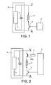
- the figure 1 represents, by way of example, a magnetic actuator circuit for a closed coil transistor vacuum interrupter of the prior art.
- the actuator circuit comprises a supply circuit A consisting, for example, of a charger 1 and a capacitor 2 connected in parallel with the charger 1, a coil 3, a transistor switch 4, a control circuit 5 of the switch transistor 4 and a permanent magnet (not shown in the figure).
- the permanent magnet locks the actuator core in the position corresponding to the closed state of the vacuum bulbs in the absence of current in the coil or coils of the actuator.
- the coil 3 and the transistor switch 4 are connected in series and form, between terminals P1 and P2, an assembly connected in parallel with the supply circuit A.
- the transistor switch 4 is, for example, a transistor which receives on its gate the switching control signal delivered by the circuit 5.
- the device controlled by closing by the actuator circuit is connected between the terminals P1 and P2 (this device is not shown in the figure).
- the accidental short-circuiting of the transistor causes the passage of a permanent current in the coil 3, which current induces a force of a few hundred to a few thousand Newtons.
- This force causes a displacement of the contacts of the vacuum bulb of a few millimeters. This displacement, even partial in the case where there is no touch contact, is not acceptable.
- the invention provides means capable of eliminating this disadvantage.
- a second electromechanical switch is mechanically connected to the first switch electromechanical so that it is the same command that controls the first electromechanical switch and the second electromechanical switch, the second electromechanical switch having a first terminal connected to a detection voltage and a second terminal connected to a voltage detection circuit.
- a signal shaping circuit is placed in series between the third electromechanical switch and the control input of the transistor switch in order to extend the duration of the control signal which is applied. on the control input of the transistor switch.
- a signal shaping circuit is placed in series between the fourth electromechanical switch and the control input of the first electromechanical switch to lengthen the duration of the control signal being applied. on the control input of the first electromechanical switch.
- a component mounted in parallel with the coil dissipates the energy released during the switching of the magnetic actuator circuit by limiting the overvoltages across the coil.
- the magnetic actuator circuit comprises two separate coils, of which a first coil is used for a switching on a high voltage device and a second coil is used to switch off the high voltage device.
- the coil is used for switching on or off a high voltage device.
- the magnetic actuator circuit of the invention has the advantage of avoiding any accidental operation of the device it controls. Because of the presence of the electromechanical switch in the actuator circuit, the current that is established in the apparatus under the action of the actuator circuit is established a little more slowly than in the prior art. This additional time of the establishment of the current is however not a disadvantage because it remains, in all cases, lower or even much lower, the closing time or opening of the device.
- the figure 2 represents a transistor actuator circuit of the invention provided with a closing coil.
- the actuator circuit of FIG. the invention comprises an electromechanical switch EM1 in series with the closing coil 3.
- the elements EM1, 3 and 4 are connected in series between the terminals P1 and P2.
- a coil b is placed, in a manner known per se, on the control circuit of the electromechanical switch EM1.
- the control signal of the electromechanical switch EM1 is delivered by the control circuit 5.
- the control circuit 5 is, for example, a microprocessor. In the idle state, the switches 4 and EM1 are in a blocked state (open circuit).
- a control signal is applied to the switch EM1 in order to close it (on state).
- a control signal is applied to the switch EM1 in order to close the latter, the switch EM1 being opened again as soon as the transistor switch 4 is placed again in open circuit.
- the mesh which gathers the electromechanical switch EM1 is advantageously in open circuit.
- a failure of the transistor control circuit 4 does not lead to any malfunction. No inadvertent operation of the apparatus controlled by the actuator circuit of the invention is then possible.
- the most common failure mode of an electromechanical switch is a permanent open state of the switch. As soon as a failure of the switch EM1 occurs, any control of the transistor switch 4 can no longer produce any effect and the apparatus which is controlled by the actuator circuit can also no longer be controlled. In this state of failure of the switch EM1, the apparatus which is controlled by the actuator circuit therefore advantageously continues to be protected from any inadvertent operation.
- the actuator circuit comprises a detection means which makes it possible to detect the state of closed switch (ie of glued relay) and this defect can then advantageously be signaled.
- the detection means is realized by an electromechanical switch EMd.
- the switch EMd has a first terminal connected to a detection voltage V 1 and a second terminal connected to a control input of the control circuit 5.
- the switch EMd is mechanically connected to the switch EM1 so that it is the same command that is applied to both switches.
- the EMd and EM1 switches are closed or opened simultaneously. It follows that when the switch EM1 is in closed mode "glued", the switch EMd is also closed and the voltage V 1 is detected by the control circuit.
- the actuator circuit then comprises an additional electromechanical switch and uses the control circuit. tripping which controls, in a manner known per se, the control circuit 5.
- the tripping circuit comprises a pulse generator 7 and an electromechanical switch EMb which has a first terminal connected to a control input of the control circuit 5 and a second terminal connected to a control voltage Vref. The pulses delivered by the generator 7 are applied to the control terminal of the switch EMb, thus making it possible to apply the control voltage Vref to the control input of the circuit 5.
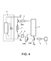
- the figure 4 represents an actuator circuit of the invention in which it is the control of the transistor switch which is sectioned.
- a third electromechanical switch EMa is placed in series between the switching circuit 5 and the control terminal of the transistor switch.
- the electromechanical switches EMa and EMb are mechanically connected so that it is the same control signal applied to them.
- a control pulse delivered by the pulse generator 7 simultaneously controls the EMa and EMb switches.
- the switch EMa is in open circuit and, advantageously, no control is applied to the transistor switch 4.
- the EMa switch closes and a control signal is applied to the transistor switch 4.
- the pulses delivered by the pulse generator have a duration generally shorter than the duration of the pulse to be applied to the coil of the actuator.
- a signal shaping circuit 6 is then placed in series between the control terminal of the transistor switch 4 and the switch EMa in order to extend the duration of the pulse which is applied to the transistor switch. For a pulse received with a duration substantially equal to 10 ms, the signal shaping circuit 6 then delivers, for example, a pulse of duration substantially equal to 100 ms which is a duration compatible with the duration of the pulses to be applied on the coil. of the actuator.
- Such a circuit advantageously avoids the circulation of an undesired current in the actuator coil.
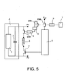
- FIG. 5 it is the control of the electromechanical switch EM1 which is cut off.
- An electromechanical switch EMc is here placed in series between the control circuit 5 and the control terminal of the electromechanical switch EM1.
- the elements EMc, EMb, 6 and 7 are used to prevent the flow of undesired current in the actuator coil.
- the figure 6 represents a third improvement of the transistor actuator circuit shown in FIG. figure 2 .
- a component 8 placed in parallel with the coil 3, for example a varistor, in which is dissipated the energy released during the switching of the actuator circuit. Overvoltages across the coil are limited to an acceptable value and the current flow time is not significantly changed.
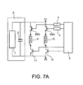
- the Figure 7A represents a first variant of a transistor actuator circuit of the invention provided with a closing coil and an opening coil.
- the circuit comprises a supply circuit A constituted, for example, by a charger 1 and a capacitor 2, a closing coil 9 series with an electromechanical switch EM2 and with a transistor switch 11, an opening coil 10 in series with an electromechanical switch EM3 and with a transistor switch 12, a control circuit 5 which delivers the control signals to the different switches and relay coils b.
- the series elements EM2, 9 and 11 constitute an assembly mounted between the terminals P1 and P2, in parallel with the assembly formed by the series elements EM3, 10 and 12.
- the switches EM2 and 11 control the opening of the device which is connected between the terminals P1 and P2 (not shown in the figure) and the switches EM1 and 12 controls the closing of this same device.
- the Figure 7B represents a second variant of a transistor actuator circuit of the invention provided with a closing coil and an opening coil.
- the closing coil 9 is connected in series between two electromechanical switches EM4 and EM5 and the opening coil 10 is connected in series between two electromechanical switches EM6 and EM7.
- the set of elements EM4, 9 and EM5 is connected in parallel with the set of elements EM6, 10 and EM7.
- the electromechanical switches EM4 and EM6 have a common terminal which is the P1 terminal and the electromechanical switches EM5 and EM7 have a common terminal which is a first terminal of a transistor switch 13 whose second terminal is the terminal P2.
- coils b are mounted on the control circuits of the various electromechanical switches. In the idle state, all switches (EM4, EM5, EM6, EM7, 13) are open (locked state).
- the electromechanical switches EM4 and EM5 are simultaneously closed (turned on) under the action of the controls applied to them shortly before the transistor switch 13 is turned off (turned on) and simultaneously opened (turned off) as soon as the transistor switch 13 is again placed in an open circuit .
- the electromechanical switches EM6 and EM7 are simultaneously closed (turned on) under the action of commands that are applied to them shortly before being closed (setting to the state) transistor switch 13 and simultaneously open (turned off) as soon as the transistor switch 13 is again placed in open circuit.
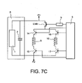
- the Figure 7C represents a third variant of a transistor actuator circuit of the invention provided with a closing coil and an opening coil.
- the closing coil 9 is connected in series between two transistor switches 14 and 15 and the opening coil 10 is connected in series between two transistor switches 16 and 17.
- the set of elements 14, 9 and 15 is connected in parallel with all of the elements 16, 10 and 17.
- the transistor switches 15 and 17 have a common terminal which is the terminal P2 and the transistor switches 14 and 16 have a common terminal which is a first terminal of an electromechanical switch EM8 whose second terminal is the terminal P1.
- coils b are mounted on the control circuits of the various electromechanical switches. In the idle state, all switches (14, 15, 16, 17, EM8) are open (off state).
- the electromechanical switch EM8 is closed (turned on) under the action of a command which is applied to it shortly before the transistor switches 14 and 15 are turned off simultaneously (turned on) and then turned on (turned off) when the transistor switches 14 and 15 are again simultaneously switched on. placed in open circuit.
- the electromechanical switch EM8 is closed (turned on) under the action of a command that is applied to it shortly before being closed. simultaneously (turning on) the transistor switches 16 and 17, and then open (turned off) as soon as the transistor switches 14 and 15 are again simultaneously placed in open circuit.
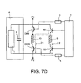
- the Figure 7D represents a fourth variant of a transistor actuator circuit of the invention provided with an opening coil and a closing coil.
- the opening coil 10 is connected in series between two electromechanical switches EM9 and EM10 and the closing coil 9 is connected in series between two transistor switches 18 and 19.
- a first terminal of the coil 9 is electrically connected to a first terminal of the coil 10, which first terminals are electrically connected to a first terminal of the electromechanical switch EM9 and to a first terminal of the transistor switch 18, the second terminals of the electromechanical switch EM9 and the transistor switch 18 being electrically connected to the terminal P1 .
- the second terminal of the coil 10 is electrically connected to a first terminal of electromechanical switch EM10 whose second terminal is electrically connected to the terminal P2 and the second terminal of the coil 9 is electrically connected to a first terminal of the transistor switch 19 whose second terminal is also connected to the terminal P2.
- all switches EM9, EM10, 18, 19
- the electromechanical switch EM10 is closed shortly before the transistor switch 18 is closed and then again open when the transistor switch 18 is placed in the open state. During this operation, switches EM9 and 19 remain in the open state. A current It travels the mesh formed by the elements 18, 10 and EM10 (see figure).
- the electromechanical switch EM9 is closed shortly before the transistor switch 19 is closed and then again opened as soon as the transistor switch 19 is placed in the open state. During this operation, switches EM10 and 18 remain in the open state. A stream 12 traverses the mesh formed by the elements EM9, 9, 19.
- FIGS 8A-8D will now be described which concern the different variants actuator of the invention in which a single coil is used, either for closing or for opening.
- the circuits represented on the Figures 8A-8D correspond, respectively, to the circuits represented on the Figures 7A-7D .
- Matching circuits it should be understood that, for the circuits concerned, the electromechanical and transistor switches are identical and are connected in the same way to the respective terminals P1 and P2.
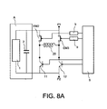
- the figure 8A represents a first variant of a transistor actuator circuit of the invention provided with a single coil for opening and closing.
- This circuit corresponds to the circuit of the Figure 7A , which means that the switches EM2, EM3, 11 and 12 are connected to the terminals P1 and P2 as in the circuit of the Figure 7A .
- the switches EM2 and 11 are connected in series as well as the switches EM3 and 12.
- a first terminal of the single coil 20 is electrically connected to a common terminal which connects the switches EM2 and 11 and the second terminal of the single coil 20 is electrically connected to a common terminal which connects the switches EM3 and 12.
- the closing circuit then consists of the elements EM3, 20 and 11 and the opening circuit of the elements EM2, 20 and 12.
- c is the EM3 switch whose closing time frames the closing of the switch 11, the EM2 and 12 switches remaining open and, for the opening operation, it is the switch EM2 whose closure time frames that of the switch 12, the switches EM3 and 11 remaining open.
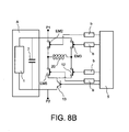
- the Figure 8B represents a second variant of a transistor actuator circuit of the invention provided with a single coil for opening and closing.
- the circuit of the Figure 8B corresponds to that of the Figure 7B . It comprises the electromechanical switches EM4, EM5, EM6 and EM7 and the transistor switch 13, which switches are connected to the respective terminals P1 and P2 in the same manner as in the circuit shown in FIG. Figure 7B .
- the single coil 20 has a first terminal connected to a common terminal of the EM4 and EM5 switches and a second terminal connected to a common terminal of the EM6 and EM7 switches.
- the closing circuit comprises the switch EM4, the coil 20, the switch EM7 and the switch 13 and the opening circuit comprises the switch EM6, the coil 20, the switch EM5 and the switch 13. For the closing operation, the EM4 and EM7 switches are closed while the EM5 and EM6 switches remain open and, for the opening operation, the EM5 and EM6 switches are closed while the EM4 and EM7 switches
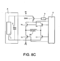
- the Figure 8C represents a third variant of a transistor actuator circuit of the invention provided with a single coil for opening and closing.
- the circuit of the Figure 8B corresponds to that of the Figure 7B . It comprises four transistor switches 14, 15, 16, 17 and an electromechanical switch EM8.
- the switches EM8, 14 and 16 are connected to the terminal P1 in the same way as in the circuit represented in FIG. Figure 7C .
- the switches 15 and 17 are connected to the terminal P2 in the same way as in the circuit represented in FIG. Figure 7C .
- the single coil 20 has a first terminal connected to a common terminal of the switches 14 and 15 and a second terminal connected to a common terminal of the switches 16 and 17.
- the closing circuit comprises the switch EM8, the switch 14, the coil 20 and the switch 17 and the opening circuit comprises the switch EM8, the switch 16, the coil 20 and the switch 15. It is the same electromechanical switch EM8 which closes for the closing operation and for the operation of opening.
- the figure 8D represents a fourth variant of a transistor actuator circuit of the invention provided with a single coil for opening and closing.
- the circuit of the figure 8D corresponds to that of the Figure 7D . It comprises two electromechanical switches EM9, EM10 and two transistor switches 18 and 19.
- the switches EM9 and 18 are connected to the terminal P1 in the same way as in the circuit represented in FIG. Figure 7D .
- the switches EM10 and 19 are connected to the terminal P2 in the same way as in the circuit represented in FIG. Figure 7D .
- the closing circuit comprises the switch 18, the coil 20 and the switch EM10 and the opening circuit comprises the switch EM9, the coil 20 and the switch 19. For the closing operation, it is the switch EM10 which is closes, the EM9 switch remaining open and, for the opening operation, the opposite is the switch EM9 which closes, the EM10 switch remaining open.
Description
La présente invention concerne un circuit actionneur magnétique d'appareillage haute tension qui contient au moins un aimant permanent et, plus particulièrement, un circuit actionneur magnétique d'appareil haute tension pour ampoule à vide, comme décrit dans
Un actionneur magnétique d'appareil haute tension est utilisé pour la mise en circuit ou la mise hors circuit d'un appareil haute tension. La mise en circuit de l'appareil haute tension est réalisée par fermeture de l'actionneur et la mise hors circuit par ouverture de l'actionneur.A high voltage device magnetic actuator is used to turn on or turn off a high voltage device. The high voltage device is switched on by closing the actuator and switching off the actuator.
Un actionneur magnétique comprend généralement une bobine de fermeture utilisée lors de la fermeture et une bobine d'ouverture utilisée lors de l'ouverture.A magnetic actuator generally comprises a closure coil used during closure and an opening coil used during opening.
Les bobines de fermeture et d'ouverture des actionneurs magnétiques présentent une isolation galvanique. Malgré cette isolation, il persiste, entre ces bobines, un couplage magnétique résiduel qui fait que la présence d'une tension sur une bobine génère une tension sur l'autre bobine. Ainsi, lors de la fermeture d'un actionneur magnétique, la tension appliquée sur la bobine de fermeture de l'actionneur génère-t-elle une tension sur la bobine d'ouverture du fait du couplage résiduel entre les bobines. Dans le cas où une ouverture succède rapidement à la fermeture (cas, par exemple, de la fermeture sur court-circuit) la tension générée sur la bobine d'ouverture s'oppose alors à la tension du signal de fermeture accroissant ainsi le courant d'ouverture et/ou le délai d'ouverture.The closing and opening coils of the magnetic actuators have a galvanic isolation. Despite this isolation, there persists between these coils, a residual magnetic coupling which makes the presence of a voltage on a coil generates a voltage on the other coil. Thus, when closing a magnetic actuator, the voltage applied to the closing coil of the actuator generates a voltage on the opening coil due to the residual coupling between the coils. In the case where an opening quickly follows the closure (case, by for example, short-circuit closure) the voltage generated on the opening coil is then opposed to the voltage of the closing signal thereby increasing the opening current and / or the opening time.
Pour les actionneurs magnétiques munis de commutateurs électromécaniques, la durée de coupure des commutateurs (durée de montée du courant dans la bobine, de déplacement des contacts y compris la durée de l'arc électrique) devient alors excessive. C'est la raison pour laquelle des commutateurs à transistor ont remplacé les commutateurs électromécaniques, les commutateurs à transistor permettant d'interrompre très rapidement le courant. Un inconvénient majeur des commutateurs à transistor réside toutefois dans le mode de défaillance le plus fréquent de ces composants, à savoir leur mise en court-circuit. La mise en court-circuit des commutateurs à transistor peut se produire en de multipples circonstances, à savoir, par exemple :
- un emballement thermique d'une partie du circuit de commande,
- une surtension d'origine interne, par exemple lors de la manoeuvre de l'appareil, ou d'origine externe, par exemple dans le cas de la foudre,
- un vieillissment précoce,
- un niveau de perturbations électromagnétiques au-delà de valeurs spécifiées,
- un mauvais câblage du contrôle commande.
- a thermal runaway of a part of the control circuit,
- an overvoltage of internal origin, for example during the operation of the device, or of external origin, for example in the case of lightning,
- early aging,
- a level of electromagnetic interference beyond specified values,
- bad wiring of the control command.
La
Le circuit actionneur comprend un circuit d'alimentation A constitué, par exemple, d'un chargeur 1 et d'un condensateur 2 monté en parallèle du chargeur 1, une bobine 3, un commutateur à transistor 4, un circuit de commande 5 du commutateur à transistor 4 et un aimant permanent (non représenté sur la figure). L'aimant permanent permet de verrouiller le noyau de l'actionneur dans la position qui correspond à l'état fermé des ampoules à vide en l'abscence de courant dans la ou les bobines de l'actionneur. La bobine 3 et le commutateur à transistor 4 sont montés en série et forment, entre des bornes P1 et P2, un ensemble monté en parallèle avec le circuit d'alimentation A. Le commutateur à transistor 4 est, par exemple, un transistor qui reçoit sur sa grille le signal de commande de commutation délivré par le circuit 5. L'appareil commandé en fermeture par le circuit actionneur est branché entre les bornes P1 et P2 (ce dispositif n'est pas représenté sur la figure). Pour un tel circuit actionneur, quel que soit le signal de commande appliqué sur la grille du transistor, la mise en court-circuit accidentelle du transistor provoque le passage d'un courant permanent dans la bobine 3, lequel courant induit une force de quelques centaines à quelques milliers de Newtons. Cette force provoque un déplacement des contacts de l'ampoule à vide de quelques millimètres. Ce déplacement, même partiel dans le cas où il n'y a pas de toucher de contact, n'est pas acceptable. L'invention prévoit des moyens aptes à supprimer cet inconvénient.The actuator circuit comprises a supply circuit A consisting, for example, of a
En effet, l'invention concerne un circuit actionneur magnétique d'appareillage haute tension pour ampoule à vide qui comprend au moins un aimant permanent et au moins une bobine montée en série avec un commutateur à transistor qui reçoit sur une borne de commande un premier signal de commande qui place le commutateur à transistor dans un état passant ou dans un état bloqué, caractérisé en ce qu'il comprend un premier commutateur électromécanique monté en série avec le commutateur à transistor et la bobine, le premier commutateur électromécanique recevant sur une borne de commande un deuxième signal de commande qui place le premier commutateur électromécanique dans un état passant ou un état bloqué, le premier commutateur électromécanique et le commutateur à transistor étant, par défaut, dans un état bloqué de sorte que le deuxième signal de commande :
- a) place le commutateur électromécanique dans un état passant à un instant qui précède l'application du premier signal de commande qui place le commutateur à transistor dans un état passant, et
- b) rétablit le commutateur électromécanique dans un état bloqué dès lors que le commutateur à transistor est rétabli dans l'état bloqué.
- a) places the electromechanical switch in an on state at a time preceding the application of the first control signal which places the transistor switch in an on state, and
- b) restores the electromechanical switch to a locked state as soon as the transistor switch is restored to the off state.
Selon une caractéristique supplémentaire de l'invention, un deuxième commutateur électromécanique est mécaniquement relié au premier commutateur électromécanique de sorte que c'est la même commande qui commande le premier commutateur électromécanique et le deuxième commutateur électromécanique, le deuxième commutateur électromécanique ayant une première borne reliée à une tension de détection et une deuxième borne reliée à un circuit de détection de tension.According to a further feature of the invention, a second electromechanical switch is mechanically connected to the first switch electromechanical so that it is the same command that controls the first electromechanical switch and the second electromechanical switch, the second electromechanical switch having a first terminal connected to a detection voltage and a second terminal connected to a voltage detection circuit.
Selon encore une autre caractéristique supplémentaire de l'invention :
- un troisième commutateur électromécanique est monté en série entre une première borne de sortie d'un circuit commutateur qui délivre le premier signal de commande et la borne de commande du commutateur à transistor, et
- un commutateur électromécanique qui appartient à un circuit d'enclenchement ou de déclenchement qui contrôle le circuit de commande est mécaniquement relié au troisième commutateur électromécanique de telle sorte que le même signal de commande commande le troisième commutateur électromécanique et le commutateur électromécanique qui appartient au circuit de déclenchement.
- a third electromechanical switch is connected in series between a first output terminal of a switch circuit which supplies the first control signal and the control terminal of the transistor switch, and
- an electromechanical switch which belongs to an interlocking or tripping circuit which controls the control circuit is mechanically connected to the third electromechanical switch so that the same control signal controls the third electromechanical switch and the electromechanical switch which belongs to the control circuit. trigger.
Selon encore une autre caractéristique supplémentaire de l'invention, un circuit de mise en forme de signal est placé en série entre le troisième commutateur électromécanique et l'entrée de commande du commutateur à transistor afin de rallonger la durée du signal de commande qui est appliqué sur l'entrée de commande du commutateur à transistor.According to still another additional characteristic of the invention, a signal shaping circuit is placed in series between the third electromechanical switch and the control input of the transistor switch in order to extend the duration of the control signal which is applied. on the control input of the transistor switch.
Selon encore une autre caractéristique supplémentaire de l'invention :
- un quatrième commutateur électromécanique est monté en série entre une deuxième borne de sortie d'un circuit de commande qui délivre le deuxième signal de commande et la borne de commande du premier commutateur électromécanique, et
- un commutateur électromécanique qui appartient à un circuit de déclenchement qui contrôle le circuit de commande est mécaniquement relié au quatrième commutateur électromécanique de telle sorte que le même signal de commande commande le quatrième commutateur électromécanique et le commutateur électromécanique qui appartient au circuit de déclenchement.
- a fourth electromechanical switch is connected in series between a second output terminal of a control circuit which outputs the second control signal and the control terminal of the first electromechanical switch, and
- an electromechanical switch which belongs to a tripping circuit which controls the control circuit is mechanically connected to the fourth electromechanical switch so that the same control signal controls the fourth electromechanical switch and the electromechanical switch which belongs to the tripping circuit.
Selon encore une autre caractéristique supplémentaire de l'invention, un circuit de mise en forme de signal est placé en série entre le quatrième commutateur électromécanique et l'entrée de commande du premier commutateur électromécanique afin de rallonger la durée du signal de commande qui est appliqué sur l'entrée de commande du premier commutateur électromécanique.According to yet another additional feature of the invention, a signal shaping circuit is placed in series between the fourth electromechanical switch and the control input of the first electromechanical switch to lengthen the duration of the control signal being applied. on the control input of the first electromechanical switch.
Selon encore une autre caractéristique supplémentaire de l'invention, un composant monté en parallèle de la bobine dissipe l'énergie libérée pendant les commutations du circuit actionneur magnétique en limitant les surtensions aux bornes de la bobine.According to yet another additional characteristic of the invention, a component mounted in parallel with the coil dissipates the energy released during the switching of the magnetic actuator circuit by limiting the overvoltages across the coil.
Selon encore une autre caractéristique supplémentaire de l'invention, le circuit actionneur magnétique comprend deux bobines distinctes parmi lesquelles une première bobine est utilisée pour une mise en circuit d'un appareil haute tension et une deuxième bobine est utilisée pour une mise hors circuit de l'appareil haute tension.According to yet another additional feature of the invention, the magnetic actuator circuit comprises two separate coils, of which a first coil is used for a switching on a high voltage device and a second coil is used to switch off the high voltage device.
Selon encore une autre caractéristique supplémentaire de l'invention, la bobine est utilisée pour une mise en circuit ou pour une mise hors circuit d'un appareil haute tension.According to yet another additional feature of the invention, the coil is used for switching on or off a high voltage device.
Le circuit actionneur magnétique de l'invention présente l'avantage d'éviter toute manoeuvre accidentelle de l'appareil qu'il commande. Du fait de la présence du commutateur électromécanique dans le circuit actionneur, le courant qui s'établit dans l'appareil sous l'action du circuit actionneur s'y établit un peu plus lentement que dans l'art antérieur. Ce délai supplémentaire de l'établissement du courant n'est toutefois pas un inconvénient car il demeure, dans tous les cas, inférieur, voire très inférieur, au délai de fermeture ou d'ouverture de l'appareil.The magnetic actuator circuit of the invention has the advantage of avoiding any accidental operation of the device it controls. Because of the presence of the electromechanical switch in the actuator circuit, the current that is established in the apparatus under the action of the actuator circuit is established a little more slowly than in the prior art. This additional time of the establishment of the current is however not a disadvantage because it remains, in all cases, lower or even much lower, the closing time or opening of the device.
D'autres caractéristiques et avantages de l'invention apparaîtront à la lecture d'un mode de réalisation préférentiel fait en référence aux figures jointes parmi lesquelles :
- La
figure 1 , déjà décrite, représente un circuit actionneur magnétique pour ampoule à vide à transistor à bobine de fermeture de l'art antérieur ; - La
figure 2 représente un circuit actionneur magnétique pour ampoule à vide à transistor à bobine de fermeture de l'invention; - La
figure 3 représente un premier perfectionnement du circuit actionneur représenté enfigure 2 ; - La
figure 4 représente une première variante d'un deuxième perfectionnement du circuit actionneur représenté enfigure 2 ; - La
figure 5 représente une deuxième variante du deuxième perfectionnement du circuit actionneur représenté enfigure 2 ; - La
figure 6 représente un troisième perfectionnement du circuit actionneur à transistor représenté enfigure 2 ; - Les
figures 7A-7D représentent différentes variantes d'un circuit actionneur à transistor de l'invention muni d'une bobine de fermeture et d'une bobine d'ouverture; - Les
figures 8A-8D représentent différentes variantes d'un circuit actionneur à transistor de l'invention muni d'une bobine unique pour la fermeture et l'ouverture ;
- The
figure 1 , already described, represents a magnetic actuator circuit for a closed coil transistor vacuum interrupter of the prior art; - The
figure 2 represents a magnetic actuator circuit for a closed coil transistor vacuum interrupter of the invention; - The
figure 3 represents a first improvement of the actuator circuit represented infigure 2 ; - The
figure 4 represents a first variant of a second improvement of the actuator circuit represented infigure 2 ; - The
figure 5 represents a second variant of the second improvement of the actuator circuit represented in FIG.figure 2 ; - The
figure 6 represents a third improvement of the transistor actuator circuit shown in FIG.figure 2 ; - The
Figures 7A-7D represent different variants of a transistor actuator circuit of the invention provided with a closing coil and an opening coil; - The
Figures 8A-8D represent different variants of a transistor actuator circuit of the invention provided with a single coil for closing and opening;
Sur toutes les figures, les mêmes références désignent les mêmes éléments.In all the figures, the same references designate the same elements.
La
Outre le circuit d'alimentation A, l'aimant permanent (non représenté sur la figure), la bobine de fermeture 3, le commutateur à transistor 4 et le circuit de commande 5, le circuit actionneur de l'invention comprend un commutateur électromécanique EM1 en série avec la bobine de fermeture 3. Les éléments EM1, 3 et 4 sont montés en série entre les bornes P1 et P2. Une bobine b est placée, de façon connue en soi, sur le circuit de commande du commutateur électromécanique EM1.. Le signal de commande du commutateur électromécanique EM1 est délivré par le circuit de commande 5. Le circuit de commande 5 est, par exemple, un microprocesseur. A l'état de repos, les commutateurs 4 et EM1 sont dans un état bloqué (circuit ouvert). Dès lors qu'il est envisagé de rendre passant le commutateur à transistor 4 (commutateur à transistor 4 fermé), un signal de commande est appliqué au commutateur EM1 afin de fermer celui-ci (état passant). Ainsi, par exemple, 5ms avant de fermer le commutateur à transistor 4, un signal de commande est-il appliqué au commutateur EM1 afin de fermer ce dernier, le commutateur EM1 étant à nouveau ouvert dès que le commutateur à transistor 4 est placé à nouveau en circuit ouvert.In addition to the power supply circuit A, the permanent magnet (not shown in the figure), the closing
Ainsi, hormis pendant une durée sensiblement identique à celle du fonctionnement du commutateur à transistor 4, la maille qui rassemble le commutateur électromécanique EM1, la bobine 3 et le commutateur à transistor 4 est-elle avantageusement en circuit ouvert. Une défaillance du circuit de commande à transistor 4 (mise en court-circuit du composant) ne conduit à aucun dysfonctionnement. Aucune manoeuvre intempestive de l'appareil commandé par le circuit actionneur de l'invention n'est alors possible.Thus, except for a period substantially identical to that of the operation of the
Le mode de défaillance le plus fréquent d'un commutateur électromécanique est une mise à l'état ouvert permanent du commutateur. Dès lors que se produit une défaillance du commutateur EM1, toute commande du commutateur à transistor 4 ne peut plus produire aucun effet et l'appareil qui est commandé par le circuit actionneur ne peut également plus être commandé. Dans cet état de défaillance du commutateur EM1, l'appareil qui est commandé par le circuit actionneur continue donc avantageusement d'être protégé de toute manoeuvre intempestive.The most common failure mode of an electromechanical switch is a permanent open state of the switch. As soon as a failure of the switch EM1 occurs, any control of the
L'autre mode de défaillance du commutateur EM1 est le mode fermé « collé ». Selon un premier perfectionnement de l'invention représenté en
Il est possible d'améliorer le fonctionnement du circuit actionneur en sectionnant soit la commande du commutateur à transistor 4, soit la commande du commutateur électromécanique EM1 comme cela est représenté, respectivement, sur les
La
Un tel circuit permet avantageusement d'éviter la circulation d'un courant non désiré dans la bobine de l'actionneur.Such a circuit advantageously avoids the circulation of an undesired current in the actuator coil.
En référence à la
La
Les
- un mode de réalisation dans lequel le circuit actionneur comprend deux bobines, l'une utilisée pour la fermeture et l'autre pour l'ouverture, et
- un mode de réalisation dans lequel le circuit actionneur comprend une seule bobine utilisée soit pour la fermeture, soit pour l'ouverture.
- an embodiment in which the actuator circuit comprises two coils, one used for closing and the other for opening, and
- an embodiment in which the actuator circuit comprises a single coil used either for closing or for opening.
La
Le circuit comprend un circuit d'alimentation A constitué, par exemple, d'un chargeur 1 et d'un condensateur 2, une bobine de fermeture 9 en série avec un commutateur électromécanique EM2 et avec un commutateur à transistor 11, une bobine d'ouverture 10 en série avec un commutateur électromécanique EM3 et avec un commutateur à transistor 12, un circuit de commande 5 qui délivre les signaux de commande aux différents commutateurs et des bobines de relais b. Les éléments en série EM2, 9 et 11 constituent un ensemble monté, entre les bornes P1 et P2, en parallèle de l'ensemble formé par les éléments en série EM3, 10 et 12. Les commutateurs EM2 et 11 contrôlent l'ouverture de l'appareil qui est branché entre les bornes P1 et P2 (non représenté sur la figure) et les commutateurs EM1 et 12 contrôle la fermeture de ce même dispositif.The circuit comprises a supply circuit A constituted, for example, by a
Tous les perfectionnements décrits en référence aux
La
Selon cette deuxième variante, la bobine de fermeture 9 est montée en série entre deux commutateurs électromécaniques EM4 et EM5 et la bobine d'ouverture 10 est montée en série entre deux commutateurs électromécaniques EM6 et EM7. L'ensemble des éléments EM4, 9 et EM5 est monté en parallèle de l'ensemble des éléments EM6, 10 et EM7. Les commutateurs électromécaniques EM4 et EM6 ont une borne commune qui est la borne P1 et les commutateurs électromécaniques EM5 et EM7 ont une borne commune qui est une première borne d'un commutateur à transistor 13 dont la deuxième borne est la borne P2. De façon connue en soi, des bobines b sont montées sur les circuits de commande des différents commutateurs électromécaniques. A l'état de repos, tous les commutateurs (EM4, EM5 , EM6, EM7, 13) sont ouverts (état bloqué).According to this second variant, the closing
Conformément à l'invention, lors de l'opération de fermeture de l'appareil qui est placé entre les bornes P1 et P2, les commutateurs électromécaniques EM4 et EM5 sont simultanément fermés (mise à l'état passant) sous l'action des commandes qui leur sont appliquées peu avant que ne soit fermé (mise à l'état passant) le commutateur à transistor 13, et simultanément ouverts (mise à l'état bloqué) dès lors que le commutateur à transistor 13 est à nouveau placé en circuit ouvert.According to the invention, during the closing operation of the apparatus which is placed between the terminals P1 and P2, the electromechanical switches EM4 and EM5 are simultaneously closed (turned on) under the action of the controls applied to them shortly before the
De même, lors de l'opération d'ouverture, les commutateurs électromécaniques EM6 et EM7 sont simultanément fermés (mise à l'état passant) sous l'action de commandes qui leur sont appliquées peu avant que ne soit fermé (mise à l'état passant) le commutateur à transistor 13 et simultanément ouverts (mise à l'état bloqué) dès lors que le commutateur à transistor 13 est à nouveau placé en circuit ouvert.Similarly, during the opening operation, the electromechanical switches EM6 and EM7 are simultaneously closed (turned on) under the action of commands that are applied to them shortly before being closed (setting to the state)
Tous les perfectionnements décrits en référence aux
La
Selon cette troisième variante, la bobine de fermeture 9 est montée en série entre deux commutateurs à transistor 14 et 15 et la bobine d'ouverture 10 est montée en série entre deux commutateurs à transistor 16 et 17. L'ensemble des éléments 14, 9 et 15 est monté en parallèle de l'ensemble des éléments 16, 10 et 17. Les commutateurs à transistor 15 et 17 ont une borne commune qui est la borne P2 et les commutateurs à transistor 14 et 16 ont une borne commune qui est une première borne d'un commutateur électromécanique EM8 dont la deuxième borne est la borne P1. De façon connue en soi, des bobines b sont montées sur les circuits de commande des différents commutateurs électromécaniques. A l'état de repos, tous les commutateurs (14, 15, 16, 17, EM8) sont ouverts (état bloqué).According to this third variant, the closing
Conformément à l'invention, lors de l'opération de fermeture de l'appareil qui est placé entre les bornes P1 et P2, le commutateur électromécanique EM8 est fermé (mise à l'état passant) sous l'action d'une commande qui lui est appliquée peu avant que ne soient fermés simultanément (mise à l'état passant) les commutateurs à transistor 14 et 15, puis ouvert (mise à l'état bloqué) dès lors que les commutateurs à transistor 14 et 15 sont à nouveau simultanément placés en circuit ouvert.According to the invention, during the closing operation of the apparatus which is placed between the terminals P1 and P2, the electromechanical switch EM8 is closed (turned on) under the action of a command which is applied to it shortly before the transistor switches 14 and 15 are turned off simultaneously (turned on) and then turned on (turned off) when the transistor switches 14 and 15 are again simultaneously switched on. placed in open circuit.
De même, conformément à l'invention, lors de l'opération d'ouverture, le commutateur électromécanique EM8 est fermé (mise à l'état passant) sous l'action d'une commande qui lui est appliquée peu avant que ne soient fermés simultanément (mise à l'état passant) les commutateurs à transistor 16 et 17, puis ouvert (mise à l'état bloqué) dès lors que les commutateurs à transistor 14 et 15 sont à nouveau simultanément placés en circuit ouvert.Similarly, according to the invention, during the opening operation, the electromechanical switch EM8 is closed (turned on) under the action of a command that is applied to it shortly before being closed. simultaneously (turning on) the transistor switches 16 and 17, and then open (turned off) as soon as the transistor switches 14 and 15 are again simultaneously placed in open circuit.
Tous les perfectionnements décrits en référence aux
La
La bobine d'ouverture 10 est montée en série entre deux commutateurs électromécaniques EM9 et EM10 et la bobine de fermeture 9 est montée en série entre deux commutateurs à transistor 18 et 19. Une première borne de la bobine 9 est électriquement reliée à une première borne de la bobine 10, lesquelles premières bornes sont électriquement reliées à une première borne du commutateur électromécanique EM9 et à une première borne du commutateur à transistor 18, les deuxièmes bornes du commutateur électromécanique EM9 et du commutateur à transistor 18 étant électriquement reliées à la borne P1. La deuxième borne de la bobine 10 est électriquement reliée à une première borne du commutateur électromécanique EM10 dont la deuxième borne est électriquement reliée à la borne P2 et la deuxième borne de la bobine 9 est électriquement reliée à une première borne du commutateur à transistor 19 dont la deuxième borne est également reliée à la borne P2. A l'état de repos, tous les commutateurs (EM9, EM10 , 18, 19) sont ouverts (état bloqué).The opening
Lors de l'opération d'ouverture de l'appareil qui est branché entre les bornes P1 et P2, le commutateur électromécanique EM10 est fermé peu avant que ne se ferme le commutateur à transistor 18 puis à nouveau ouvert dès lors que le commutateur à transistor 18 est placé à l'état ouvert. Durant cette opération, les commutateurs EM9 et 19 restent à l'état ouvert. Un courant Il parcourt la maille formée par les éléments 18, 10 et EM10 (voir figure). Lors de l'opération de fermeture, le commutateur électromécanique EM9 est fermé peu avant que ne se ferme le commutateur à transistor 19 puis à nouveau ouvert dès lors que le commutateur à transistor 19 est placé à l'état ouvert. Durant cette opération, les commutateurs EM10 et 18 restent à l'état ouvert. Un courant 12 parcourt la maille formée par les éléments EM9, 9, 19.During the opening operation of the apparatus which is connected between the terminals P1 and P2, the electromechanical switch EM10 is closed shortly before the
Tous les perfectionnements décrits en référence aux
Les
La
Les commutateurs EM2 et 11 sont montés en série de même que les commutateurs EM3 et 12. Une première borne de la bobine unique 20 est électriquement reliée à une borne commune qui relie les commutateurs EM2 et 11 et la deuxième borne de la bobine unique 20 est électriquement reliée à une borne commune qui relie les commutateurs EM3 et 12. Le circuit de fermeture est alors constitué des éléments EM3, 20 et 11 et le circuit d'ouverture des éléments EM2, 20 et 12. Pour l'opération de fermeture, c'est le commutateur EM3 dont la durée de fermeture encadre la fermeture du commutateur 11, les commutateurs EM2 et 12 restant ouverts et, pour l'opération d'ouverture, c'est le commutateur EM2 dont la durée de fermeture encadre celle du commutateur 12, les commutateurs EM3 et 11 restant ouverts.The switches EM2 and 11 are connected in series as well as the switches EM3 and 12. A first terminal of the
Tous les perfectionnements décrits en référence aux
La
Tous les perfectionnements décrits en référence aux
La
Tous les perfectionnements décrits en référence aux
La
Tous les perfectionnements décrits en référence aux
Claims (9)
- A magnetic actuator circuit for connecting or disconnecting high-voltage switchgear for a vacuum circuit breaker, the actuator circuit comprising at least one permanent magnet and at least one coil (3) connected in series with a transistor switch (4) that receives, on a control terminal, a first control signal that puts the transistor switch in a closed state or an open state, the actuator circuit being characterized in that it comprises a first electromechanical switch (EM1) connected in series with the transistor switch and controlled by a second control signal that puts the first electromechanical switch into a closed or an open state, the first electromechanical switch and the transistor switch being, by default, in an open state before any connecting or disconnecting of the high-voltage switchgear for vacuum circuit breaker, the second control signal:a) putting the electromechanical switch in a closed state at an instant prior to the application of the first control signal that puts the transistor switch in its closed state; andb) returning the electromechanical switch to its open state once the transistor switch has been returned to its open state.
- An actuator circuit according to claim 1, wherein a second electromechanical switch (EMd) is coupled mechanically to the first electromechanical switch (EM1), so that the first electromechanical switch (EM1) and the second electromechanical switch (EMd) are controlled by a common control signal, the second electromechanical switch having a first terminal connected to a detection voltage (V1) and a second terminal connected to a voltage detection circuit.
- An actuator circuit according to claim 1 or claim 2, wherein:· a third electromechanical switch (EMa) is connected in series between a first output terminal of a control circuit (5) that is arranged to deliver said first control signal, and the control terminal of the transistor switch (4); and· an electromechanical switch (EMb), which is part of a trigger circuit (EMb, 7, Vref) that operates the control circuit (5), is coupled mechanically to the third electromechanical switch (EMa) so that the third electromechanical switch and the electromechanical switch (EMb) that is part of the trigger circuit are controlled by a common control signal.
- An actuator circuit according to claim 3, wherein a signal shaping circuit (6) is connected in series between the third electromechanical switch and the control input of the transistor switch, in such a way as to prolong the duration of the control signal that is applied to the control input of the transistor switch.
- An actuator circuit according to claim 1 or claim 2, wherein:· a fourth electromechanical switch (EMc) is connected in series between a second output terminal of a control circuit (5) arranged for delivering the second control signal, and the control terminal of the first electromechanical switch (EM1); and· an electromechanical switch (EMb), which is part of a trigger circuit (EMb, 7, Vref) that operates the control circuit (5), is coupled mechanically to the fourth electromechanical switch (EMc) so that the fourth electromechanical switch (EMc) and the electromechanical switch (EMb) that is part of the trigger circuit are controlled by a common control signal.
- An actuator circuit according to claim 5, wherein a signal shaping circuit (6) is connected in series between the fourth electromechanical switch and the control input of the first electromechanical switch, in such a way as to prolong the duration of the control signal that is applied to the control input of the first electromechanical switch.
- An actuator circuit according to any preceding claim, wherein a component (8) connected in parallel with said coil (3) is arranged for dissipating the energy that is released during switching operations of the magnetic actuator, by limiting over-voltages between the ends of the coil.
- An actuator circuit according to any preceding claim, characterized in that it has two separate coils, consisting of a first coil (9) arranged to be used for putting a high voltage apparatus in circuit and a second coil (10) arranged to be used for taking the high voltage apparatus out of circuit.
- An actuator circuit according to any one of claims 1 to 7, wherein the coil (20) is arranged to be used for putting in circuit or taking out of circuit, a medium and/or high voltage apparatus.
Applications Claiming Priority (2)
| Application Number | Priority Date | Filing Date | Title |
|---|---|---|---|
| FR0951492A FR2943170B1 (en) | 2009-03-10 | 2009-03-10 | MAGNETIC ACTUATOR CIRCUIT |
| PCT/EP2010/052949 WO2010102989A1 (en) | 2009-03-10 | 2010-03-09 | Circuit for controlling an electromagnetic actuator for a vacuum switch |
Publications (2)
| Publication Number | Publication Date |
|---|---|
| EP2406802A1 EP2406802A1 (en) | 2012-01-18 |
| EP2406802B1 true EP2406802B1 (en) | 2014-11-12 |
Family
ID=41061269
Family Applications (1)
| Application Number | Title | Priority Date | Filing Date |
|---|---|---|---|
| EP10709995.4A Not-in-force EP2406802B1 (en) | 2009-03-10 | 2010-03-09 | Control circuit for an electromagnetic actuator for a vacuum interrupter |
Country Status (7)
| Country | Link |
|---|---|
| US (1) | US8569645B2 (en) |
| EP (1) | EP2406802B1 (en) |
| CN (1) | CN102414766B (en) |
| AU (1) | AU2010223361B2 (en) |
| ES (1) | ES2526250T3 (en) |
| FR (1) | FR2943170B1 (en) |
| WO (1) | WO2010102989A1 (en) |
Families Citing this family (11)
| Publication number | Priority date | Publication date | Assignee | Title |
|---|---|---|---|---|
| US20130182479A1 (en) * | 2012-01-17 | 2013-07-18 | Hamilton Sundstrand Corporation | Variable voltage reference in power rectification |
| US9343216B2 (en) * | 2013-09-02 | 2016-05-17 | Glen A. Robertson | Energy efficient bi-stable permanent magnet actuation system |
| CN103916080B (en) * | 2014-04-17 | 2017-01-25 | 西北工业大学 | Small-area high-linearity shaping circuit |
| US20150332883A1 (en) * | 2014-05-14 | 2015-11-19 | Eaton Corporation | Electrical switching apparatus and linear actuator assembly therefor |
| FR3023648B1 (en) * | 2014-07-09 | 2016-07-01 | Schneider Electric Ind Sas | EMERGENCY STOP DEVICE |
| EP3051568B1 (en) * | 2015-01-30 | 2019-03-13 | General Electric Technology GmbH | Operating mechanism for tripping a voltage circuit breaker |
| CN105470041A (en) * | 2015-12-16 | 2016-04-06 | 国网浙江省电力公司电力科学研究院 | Quick high-voltage switch |
| WO2018037547A1 (en) * | 2016-08-26 | 2018-03-01 | 三菱電機株式会社 | Electromagnetic operation mechanism drive circuit |
| EP3532333B1 (en) | 2016-10-25 | 2022-12-21 | CPS Technology Holdings LLC | Battery module parallel switching device systems and methods |
| CN106409607B (en) * | 2016-11-30 | 2018-09-25 | 滁州学院 | The permanent-magnet breaker divide-shut brake intelligent control module of the simple and quick switch type of relay |
| WO2023283455A1 (en) * | 2021-07-08 | 2023-01-12 | Astronics Advanced Electronic Systems Corp. | Method and apparatus for handling contactor/relay contact bounce under transient conditions |
Family Cites Families (12)
| Publication number | Priority date | Publication date | Assignee | Title |
|---|---|---|---|---|
| US3790862A (en) * | 1972-12-21 | 1974-02-05 | Square D Co | Excitation control circuit for electromagnet coil |
| US4860157A (en) * | 1988-04-25 | 1989-08-22 | General Electric Company | Molded case circuit breaker actuator-accessory module |
| DE4034485A1 (en) * | 1990-10-30 | 1992-05-07 | Ernst H Grundmann | LOW VOLTAGE SWITCHGEAR |
| US5375027A (en) * | 1992-09-29 | 1994-12-20 | General Dynamics Corporation | Fail safe cartridge fire unit |
| DE29614718U1 (en) * | 1996-08-13 | 1996-10-17 | Siemens Ag | trigger |
| DE19734589B4 (en) * | 1997-04-13 | 2005-12-08 | Elan Schaltelemente Gmbh & Co. Kg | Electronic security module |
| US6013889A (en) * | 1997-06-02 | 2000-01-11 | Allen-Bradley Company, Llc | Method for retaining a movable contact in a circuit interrupter |
| DE19731269B4 (en) * | 1997-07-22 | 2006-02-23 | Hager Electro Gmbh | Device for switching electrical contacts |
| DE19929572A1 (en) * | 1999-06-22 | 2001-01-04 | Siemens Ag | Magnetic linear drive |
| JP4284876B2 (en) * | 2001-03-13 | 2009-06-24 | パナソニック株式会社 | Electric floor heater |
| US7715168B2 (en) * | 2006-05-08 | 2010-05-11 | Asco Power Technologies Lp | Controlled solenoid drive circuit |
| US7804038B2 (en) * | 2007-09-28 | 2010-09-28 | Rockwell Automation Technologies, Inc. | Multi-vacuum contactor control system |
-
2009
- 2009-03-10 FR FR0951492A patent/FR2943170B1/en not_active Expired - Fee Related
-
2010
- 2010-03-09 EP EP10709995.4A patent/EP2406802B1/en not_active Not-in-force
- 2010-03-09 CN CN201080019436.5A patent/CN102414766B/en not_active Expired - Fee Related
- 2010-03-09 AU AU2010223361A patent/AU2010223361B2/en not_active Ceased
- 2010-03-09 ES ES10709995.4T patent/ES2526250T3/en active Active
- 2010-03-09 WO PCT/EP2010/052949 patent/WO2010102989A1/en active Application Filing
- 2010-03-09 US US13/254,673 patent/US8569645B2/en not_active Expired - Fee Related
Also Published As
| Publication number | Publication date |
|---|---|
| AU2010223361A1 (en) | 2011-10-13 |
| US8569645B2 (en) | 2013-10-29 |
| CN102414766B (en) | 2014-10-22 |
| FR2943170A1 (en) | 2010-09-17 |
| EP2406802A1 (en) | 2012-01-18 |
| ES2526250T3 (en) | 2015-01-08 |
| US20110315663A1 (en) | 2011-12-29 |
| CN102414766A (en) | 2012-04-11 |
| AU2010223361B2 (en) | 2014-09-04 |
| WO2010102989A1 (en) | 2010-09-16 |
| FR2943170B1 (en) | 2013-03-22 |
Similar Documents
| Publication | Publication Date | Title |
|---|---|---|
| EP2406802B1 (en) | Control circuit for an electromagnetic actuator for a vacuum interrupter | |
| FR2584858A1 (en) | CIRCUIT SWITCH WITHOUT ARC FORMATION | |
| EP3459100B1 (en) | Breaker device intended to be linked to an electrical circuit | |
| FR2738664A1 (en) | Hybrid suppressor utilising Miller effect for suppressing arcs formed at contacts of electrical switch | |
| FR2853132A1 (en) | OPERATING CIRCUIT AND POWER SWITCHING DEVICE USING SUCH A CIRCUIT. | |
| EP0204624B1 (en) | Device for monitoring the state of an electric switch and its use in an electric relay | |
| EP2842151B1 (en) | Driver circuit for a circuit breaker | |
| FR2997196A1 (en) | HIGH VOLTAGE CIRCUIT CIRCUIT FOR HIGH CONTINUOUS CURRENT CIRCUIT CIRCUIT BREAKER | |
| EP0780861B1 (en) | Electrical device with arc commutation | |
| FR2870986A1 (en) | RELAY CONTROL DEVICE FOR DIRECT CURRENT ELECTRICAL APPARATUS | |
| FR3036222A1 (en) | METHOD FOR CONTROLLING A CHANGE IN THE OPERATING STATE OF AN ELECTROMECHANICAL MEMBER, FOR EXAMPLE A RELAY, AND CORRESPONDING DEVICE | |
| EP2555216B1 (en) | Electric appliance comprising two control terminals for placing a mobile unit selectively in the rest position and in the working position | |
| EP4016570A1 (en) | Electromechanical switching device for an electric power circuit | |
| EP3437115B1 (en) | Hybridisation system for high voltage direct current | |
| EP3291271B1 (en) | Control method for an actuating device, related actuating device and switching device | |
| EP2192605A1 (en) | Device for disconnecting an electric circuit and electricity distribution box comprising such a disconnecting device | |
| CH623276A5 (en) | ||
| EP3699942A1 (en) | Operating system for a vacuum bulb | |
| EP1628378B1 (en) | Overvoltage protection device comprising parallel spark gaps | |
| EP0834975A1 (en) | Electrical distribution terminal with hybrid limiter block | |
| EP4139946B1 (en) | Circuit breaker with electronic trip control | |
| EP4167261A1 (en) | Electric switching device and associated switching system and method | |
| EP1473749B1 (en) | Control device with hysteresis | |
| WO2021180658A1 (en) | Hybrid switch and control device | |
| WO2005001868A1 (en) | Switching electrical device having a number of actuators |
Legal Events
| Date | Code | Title | Description |
|---|---|---|---|
| PUAI | Public reference made under article 153(3) epc to a published international application that has entered the european phase |
Free format text: ORIGINAL CODE: 0009012 |
|
| 17P | Request for examination filed |
Effective date: 20110909 |
|
| AK | Designated contracting states |
Kind code of ref document: A1 Designated state(s): AT BE BG CH CY CZ DE DK EE ES FI FR GB GR HR HU IE IS IT LI LT LU LV MC MK MT NL NO PL PT RO SE SI SK SM TR |
|
| DAX | Request for extension of the european patent (deleted) | ||
| GRAP | Despatch of communication of intention to grant a patent |
Free format text: ORIGINAL CODE: EPIDOSNIGR1 |
|
| INTG | Intention to grant announced |
Effective date: 20140604 |
|
| GRAS | Grant fee paid |
Free format text: ORIGINAL CODE: EPIDOSNIGR3 |
|
| GRAA | (expected) grant |
Free format text: ORIGINAL CODE: 0009210 |
|
| AK | Designated contracting states |
Kind code of ref document: B1 Designated state(s): AT BE BG CH CY CZ DE DK EE ES FI FR GB GR HR HU IE IS IT LI LT LU LV MC MK MT NL NO PL PT RO SE SI SK SM TR |
|
| REG | Reference to a national code |
Ref country code: GB Ref legal event code: FG4D Free format text: NOT ENGLISH |
|
| REG | Reference to a national code |
Ref country code: CH Ref legal event code: EP |
|
| REG | Reference to a national code |
Ref country code: AT Ref legal event code: REF Ref document number: 696191 Country of ref document: AT Kind code of ref document: T Effective date: 20141115 |
|
| REG | Reference to a national code |
Ref country code: IE Ref legal event code: FG4D Free format text: LANGUAGE OF EP DOCUMENT: FRENCH |
|
| REG | Reference to a national code |
Ref country code: DE Ref legal event code: R096 Ref document number: 602010020119 Country of ref document: DE Effective date: 20141224 |
|
| REG | Reference to a national code |
Ref country code: ES Ref legal event code: FG2A Ref document number: 2526250 Country of ref document: ES Kind code of ref document: T3 Effective date: 20150108 |
|
| REG | Reference to a national code |
Ref country code: NL Ref legal event code: VDEP Effective date: 20141112 |
|
| REG | Reference to a national code |
Ref country code: AT Ref legal event code: MK05 Ref document number: 696191 Country of ref document: AT Kind code of ref document: T Effective date: 20141112 |
|
| PG25 | Lapsed in a contracting state [announced via postgrant information from national office to epo] |
Ref country code: NL Free format text: LAPSE BECAUSE OF FAILURE TO SUBMIT A TRANSLATION OF THE DESCRIPTION OR TO PAY THE FEE WITHIN THE PRESCRIBED TIME-LIMIT Effective date: 20141112 Ref country code: PT Free format text: LAPSE BECAUSE OF FAILURE TO SUBMIT A TRANSLATION OF THE DESCRIPTION OR TO PAY THE FEE WITHIN THE PRESCRIBED TIME-LIMIT Effective date: 20150312 Ref country code: FI Free format text: LAPSE BECAUSE OF FAILURE TO SUBMIT A TRANSLATION OF THE DESCRIPTION OR TO PAY THE FEE WITHIN THE PRESCRIBED TIME-LIMIT Effective date: 20141112 Ref country code: IS Free format text: LAPSE BECAUSE OF FAILURE TO SUBMIT A TRANSLATION OF THE DESCRIPTION OR TO PAY THE FEE WITHIN THE PRESCRIBED TIME-LIMIT Effective date: 20150312 Ref country code: NO Free format text: LAPSE BECAUSE OF FAILURE TO SUBMIT A TRANSLATION OF THE DESCRIPTION OR TO PAY THE FEE WITHIN THE PRESCRIBED TIME-LIMIT Effective date: 20150212 Ref country code: LT Free format text: LAPSE BECAUSE OF FAILURE TO SUBMIT A TRANSLATION OF THE DESCRIPTION OR TO PAY THE FEE WITHIN THE PRESCRIBED TIME-LIMIT Effective date: 20141112 |
|
| PG25 | Lapsed in a contracting state [announced via postgrant information from national office to epo] |
Ref country code: LV Free format text: LAPSE BECAUSE OF FAILURE TO SUBMIT A TRANSLATION OF THE DESCRIPTION OR TO PAY THE FEE WITHIN THE PRESCRIBED TIME-LIMIT Effective date: 20141112 Ref country code: PL Free format text: LAPSE BECAUSE OF FAILURE TO SUBMIT A TRANSLATION OF THE DESCRIPTION OR TO PAY THE FEE WITHIN THE PRESCRIBED TIME-LIMIT Effective date: 20141112 Ref country code: SE Free format text: LAPSE BECAUSE OF FAILURE TO SUBMIT A TRANSLATION OF THE DESCRIPTION OR TO PAY THE FEE WITHIN THE PRESCRIBED TIME-LIMIT Effective date: 20141112 Ref country code: GR Free format text: LAPSE BECAUSE OF FAILURE TO SUBMIT A TRANSLATION OF THE DESCRIPTION OR TO PAY THE FEE WITHIN THE PRESCRIBED TIME-LIMIT Effective date: 20150213 Ref country code: AT Free format text: LAPSE BECAUSE OF FAILURE TO SUBMIT A TRANSLATION OF THE DESCRIPTION OR TO PAY THE FEE WITHIN THE PRESCRIBED TIME-LIMIT Effective date: 20141112 Ref country code: HR Free format text: LAPSE BECAUSE OF FAILURE TO SUBMIT A TRANSLATION OF THE DESCRIPTION OR TO PAY THE FEE WITHIN THE PRESCRIBED TIME-LIMIT Effective date: 20141112 Ref country code: CY Free format text: LAPSE BECAUSE OF FAILURE TO SUBMIT A TRANSLATION OF THE DESCRIPTION OR TO PAY THE FEE WITHIN THE PRESCRIBED TIME-LIMIT Effective date: 20141112 |
|
| PG25 | Lapsed in a contracting state [announced via postgrant information from national office to epo] |
Ref country code: SK Free format text: LAPSE BECAUSE OF FAILURE TO SUBMIT A TRANSLATION OF THE DESCRIPTION OR TO PAY THE FEE WITHIN THE PRESCRIBED TIME-LIMIT Effective date: 20141112 Ref country code: DK Free format text: LAPSE BECAUSE OF FAILURE TO SUBMIT A TRANSLATION OF THE DESCRIPTION OR TO PAY THE FEE WITHIN THE PRESCRIBED TIME-LIMIT Effective date: 20141112 Ref country code: EE Free format text: LAPSE BECAUSE OF FAILURE TO SUBMIT A TRANSLATION OF THE DESCRIPTION OR TO PAY THE FEE WITHIN THE PRESCRIBED TIME-LIMIT Effective date: 20141112 Ref country code: CZ Free format text: LAPSE BECAUSE OF FAILURE TO SUBMIT A TRANSLATION OF THE DESCRIPTION OR TO PAY THE FEE WITHIN THE PRESCRIBED TIME-LIMIT Effective date: 20141112 Ref country code: RO Free format text: LAPSE BECAUSE OF FAILURE TO SUBMIT A TRANSLATION OF THE DESCRIPTION OR TO PAY THE FEE WITHIN THE PRESCRIBED TIME-LIMIT Effective date: 20141112 |
|
| REG | Reference to a national code |
Ref country code: DE Ref legal event code: R097 Ref document number: 602010020119 Country of ref document: DE |
|
| PLBE | No opposition filed within time limit |
Free format text: ORIGINAL CODE: 0009261 |
|
| 26N | No opposition filed |
Effective date: 20150813 |
|
| PG25 | Lapsed in a contracting state [announced via postgrant information from national office to epo] |
Ref country code: MC Free format text: LAPSE BECAUSE OF FAILURE TO SUBMIT A TRANSLATION OF THE DESCRIPTION OR TO PAY THE FEE WITHIN THE PRESCRIBED TIME-LIMIT Effective date: 20141112 Ref country code: LU Free format text: LAPSE BECAUSE OF FAILURE TO SUBMIT A TRANSLATION OF THE DESCRIPTION OR TO PAY THE FEE WITHIN THE PRESCRIBED TIME-LIMIT Effective date: 20150309 |
|
| REG | Reference to a national code |
Ref country code: CH Ref legal event code: PL |
|
| REG | Reference to a national code |
Ref country code: IE Ref legal event code: MM4A |
|
| PG25 | Lapsed in a contracting state [announced via postgrant information from national office to epo] |
Ref country code: LI Free format text: LAPSE BECAUSE OF NON-PAYMENT OF DUE FEES Effective date: 20150331 Ref country code: CH Free format text: LAPSE BECAUSE OF NON-PAYMENT OF DUE FEES Effective date: 20150331 Ref country code: IE Free format text: LAPSE BECAUSE OF NON-PAYMENT OF DUE FEES Effective date: 20150309 |
|
| PG25 | Lapsed in a contracting state [announced via postgrant information from national office to epo] |
Ref country code: SI Free format text: LAPSE BECAUSE OF FAILURE TO SUBMIT A TRANSLATION OF THE DESCRIPTION OR TO PAY THE FEE WITHIN THE PRESCRIBED TIME-LIMIT Effective date: 20141112 |
|
| REG | Reference to a national code |
Ref country code: FR Ref legal event code: PLFP Year of fee payment: 7 |
|
| PGFP | Annual fee paid to national office [announced via postgrant information from national office to epo] |
Ref country code: DE Payment date: 20160310 Year of fee payment: 7 |
|
| PGFP | Annual fee paid to national office [announced via postgrant information from national office to epo] |
Ref country code: FR Payment date: 20160308 Year of fee payment: 7 Ref country code: GB Payment date: 20160309 Year of fee payment: 7 |
|
| PGFP | Annual fee paid to national office [announced via postgrant information from national office to epo] |
Ref country code: IT Payment date: 20160324 Year of fee payment: 7 |
|
| PG25 | Lapsed in a contracting state [announced via postgrant information from national office to epo] |
Ref country code: MT Free format text: LAPSE BECAUSE OF FAILURE TO SUBMIT A TRANSLATION OF THE DESCRIPTION OR TO PAY THE FEE WITHIN THE PRESCRIBED TIME-LIMIT Effective date: 20141112 |
|
| PG25 | Lapsed in a contracting state [announced via postgrant information from national office to epo] |
Ref country code: BG Free format text: LAPSE BECAUSE OF FAILURE TO SUBMIT A TRANSLATION OF THE DESCRIPTION OR TO PAY THE FEE WITHIN THE PRESCRIBED TIME-LIMIT Effective date: 20141112 Ref country code: HU Free format text: LAPSE BECAUSE OF FAILURE TO SUBMIT A TRANSLATION OF THE DESCRIPTION OR TO PAY THE FEE WITHIN THE PRESCRIBED TIME-LIMIT; INVALID AB INITIO Effective date: 20100309 Ref country code: SM Free format text: LAPSE BECAUSE OF FAILURE TO SUBMIT A TRANSLATION OF THE DESCRIPTION OR TO PAY THE FEE WITHIN THE PRESCRIBED TIME-LIMIT Effective date: 20141112 |
|
| PGFP | Annual fee paid to national office [announced via postgrant information from national office to epo] |
Ref country code: ES Payment date: 20170214 Year of fee payment: 8 |
|
| PG25 | Lapsed in a contracting state [announced via postgrant information from national office to epo] |
Ref country code: BE Free format text: LAPSE BECAUSE OF NON-PAYMENT OF DUE FEES Effective date: 20150331 |
|
| PG25 | Lapsed in a contracting state [announced via postgrant information from national office to epo] |
Ref country code: TR Free format text: LAPSE BECAUSE OF FAILURE TO SUBMIT A TRANSLATION OF THE DESCRIPTION OR TO PAY THE FEE WITHIN THE PRESCRIBED TIME-LIMIT Effective date: 20141112 |
|
| REG | Reference to a national code |
Ref country code: DE Ref legal event code: R119 Ref document number: 602010020119 Country of ref document: DE |
|
| GBPC | Gb: european patent ceased through non-payment of renewal fee |
Effective date: 20170309 |
|
| REG | Reference to a national code |
Ref country code: FR Ref legal event code: ST Effective date: 20171130 |
|
| PG25 | Lapsed in a contracting state [announced via postgrant information from national office to epo] |
Ref country code: FR Free format text: LAPSE BECAUSE OF NON-PAYMENT OF DUE FEES Effective date: 20170331 Ref country code: DE Free format text: LAPSE BECAUSE OF NON-PAYMENT OF DUE FEES Effective date: 20171003 |
|
| PG25 | Lapsed in a contracting state [announced via postgrant information from national office to epo] |
Ref country code: IT Free format text: LAPSE BECAUSE OF NON-PAYMENT OF DUE FEES Effective date: 20170309 Ref country code: GB Free format text: LAPSE BECAUSE OF NON-PAYMENT OF DUE FEES Effective date: 20170309 |
|
| PG25 | Lapsed in a contracting state [announced via postgrant information from national office to epo] |
Ref country code: MK Free format text: LAPSE BECAUSE OF FAILURE TO SUBMIT A TRANSLATION OF THE DESCRIPTION OR TO PAY THE FEE WITHIN THE PRESCRIBED TIME-LIMIT Effective date: 20141112 |
|
| REG | Reference to a national code |
Ref country code: ES Ref legal event code: FD2A Effective date: 20190903 |
|
| PG25 | Lapsed in a contracting state [announced via postgrant information from national office to epo] |
Ref country code: ES Free format text: LAPSE BECAUSE OF NON-PAYMENT OF DUE FEES Effective date: 20180310 |
|
| PLAA | Information modified related to event that no opposition was filed |
Free format text: ORIGINAL CODE: 0009299DELT |
|
| PLBE | No opposition filed within time limit |
Free format text: ORIGINAL CODE: 0009261 |
|
| STAA | Information on the status of an ep patent application or granted ep patent |
Free format text: STATUS: NO OPPOSITION FILED WITHIN TIME LIMIT |
|
| R26N | No opposition filed (corrected) |
Effective date: 20150813 |
|
| RIN2 | Information on inventor provided after grant (corrected) |
Inventor name: BONJEAN, ELOISE |
|
| 26N | No opposition filed |
Effective date: 20150813 |